EP1399679B1 - Luftauslasseinheit für grosse gebläseanordnung - Google Patents
Luftauslasseinheit für grosse gebläseanordnung Download PDFInfo
- Publication number
- EP1399679B1 EP1399679B1 EP01938008A EP01938008A EP1399679B1 EP 1399679 B1 EP1399679 B1 EP 1399679B1 EP 01938008 A EP01938008 A EP 01938008A EP 01938008 A EP01938008 A EP 01938008A EP 1399679 B1 EP1399679 B1 EP 1399679B1
- Authority
- EP
- European Patent Office
- Prior art keywords
- tube member
- downstream
- air outlet
- inner tube
- outer end
- Prior art date
- Legal status (The legal status is an assumption and is not a legal conclusion. Google has not performed a legal analysis and makes no representation as to the accuracy of the status listed.)
- Expired - Lifetime
Links
Images


Classifications
-
- F—MECHANICAL ENGINEERING; LIGHTING; HEATING; WEAPONS; BLASTING
- F04—POSITIVE - DISPLACEMENT MACHINES FOR LIQUIDS; PUMPS FOR LIQUIDS OR ELASTIC FLUIDS
- F04D—NON-POSITIVE-DISPLACEMENT PUMPS
- F04D29/00—Details, component parts, or accessories
- F04D29/40—Casings; Connections of working fluid
- F04D29/52—Casings; Connections of working fluid for axial pumps
- F04D29/54—Fluid-guiding means, e.g. diffusers
- F04D29/541—Specially adapted for elastic fluid pumps
Definitions
- the present invention relates to an air outlet unit for a large blower assembly comprising an outlet tube member with an upstream inner end in flow communication with the pressure side of an impeller of the blower assembly and a downstream outer end for connection with a duct and a mainly cylindrical inner tube member arranged coaxially to the outlet tube member and having an inner end substantially aligned with the inner end of the outlet tube member and a downstream outer end, the inner tube member being closed by a closing means.
- a unit is known eg from FR-A-891380.
- blower assemblies for power stations, fluidized bed systems, tunnels and the like
- the power of the motor to drive the impeller may be 700 kW or even more, so the efficiency of the blower assembly is of critical importance.
- the development of larger blower assemblies has furthermore tightened the requirements for the different parts as the velocity and pressure of the fluid increases.
- An object of the present invention is to provide an air outlet unit with improved efficiency, i.e. reduced pressure loss and a more uniform velocity profile.
- the air outlet unit according to the invention is characterized in that the inner tube member has an open downstream end projecting in the downstream direction beyond the downstream outer end of the outlet tube member.
- the impact of the open downstream end is that the recirculating flow and/or eddies are more or less contained in the open end of the inner tube so that they only to a limited extent disturb the flow, and maybe even have a positive influence on the flow. Further is obtained an improvement of the flow, so the velocity profile is smoothed out to an ideal profile in a shorter distance after the air outlet in comparison with the known construction.
- the air outlet unit is characterized in that the length of the projecting downstream end of the inner tube member from the downstream outer end of the outlet tube member to the downstream end of said projecting end is in the range from 0.25 ⁇ D to 1.5 ⁇ D, preferably about 1 ⁇ D, where D is the diameter of the inner tube member.
- the air outlet unit is characterized in that the inner tube member comprises a base section and an extension tube element.
- the inner tube member comprises a base section and an extension tube element.
- the air outlet unit is characterized in that the closing means of the inner tube member is placed somewhere between the inner end of the inner tube and a position in alignment with the downstream outer end of the outlet tube member.
- the function of the closing means is to close off the inner tube so no return flow will go through the inner tube.
- This closing means may be positioned anywhere between the inner end of the inner tube and a position in alignment with the downstream end of the outlet tube.
- a special type of air outlet unit is a diffuser, the objective of which is to expand the flow of air or exhaust gasses from one area of flow, corresponding to the size of the blower, to a larger cross section area corresponding to the succeeding channel. As the area of flow expands the flow is retarded and pressure increases. This means that the fluid is flowing against an adverse pressure gradient, and as a consequence there is an even higher risk of separation and/or recirculation of the flow in or after the diffuser than in other air outlet units, and this will have a strong negative influence on the efficiency of the blower assembly.
- diffusers recirculating flow and eddies are generated at the end of the inner tube, and this has a detrimental effect on the fluid flow. The recirculating flow and the eddies cause a flow change (change of velocity profile), which will not be smoothed out till a long distance after the diffuser, and which in the worst case result in an unwanted loss because of shock waves in the fluid.
- the air outlet unit is a diffuser with an outlet tube member having slightly diverging walls in the downstream direction.
- the air outlet unit is a nozzle with an outlet tube member having slightly converging walls in the downstream direction.
- the blower assembly 2 includes a suction box 7 with an inlet for air, an impeller 4 and a diffuser 1.
- the impeller 4 is driven by a motor 8 connected to the impeller 4 by a shaft 9 extending through the suction box 7.
- a tubular body 10 through the suction box 7 contains the shaft 9, main bearings 11 and any other equipment.
- a fluid e.g. air to a power station or smoke gas exhaust from a power station is drawn in by the impeller 4 into the suction box 7 in the direction shown by the arrow A, and the suction box 7 imparts a change of flow direction from the inlet to the impeller 4.
- the impeller 4 with blades is rotated by the shaft 9 connected to the motor 8, while the blades in turn provides an increase in pressure in the fluid.
- the shaft 9 passes through the suction box 7 in the tubular body 10, which may also hold main bearings 11 for the shaft 9, conduits for sealing air, and equipment necessary or useful for the function, monitoring or control of the blower.
- the dimensions of the tubular body 10 is usually rather large, e.g. for a impeller 4 with a diameter at the blade tip of 3200 mm, the diameter of the tubular body 10 may be 1600 mm.
- the prior art diffuser shown in Fig. 2 has a mainly cylindrical inner tube member 5 and diverging outer walls, to which the inner tube member 5 is connected by a series of spacers 12 at each end of the diffuser 1.
- the diffuser 1 will normally be connected to a duct at a flange 13 arranged at its downstream end, and at the interface between the diffuser 1 and the duct, the fluid flow experiences a sudden area increase.
- the inner tube member 5 is closed by a closing means 6 in the form of a wall, positioned approximately in alignment with the connecting flange 13.
- the fluid flow separates at the downstream end of the inner tube member 5 and a recirculating flow arises immediately downstream of the tube end. This recirculating flow causes a change of effective geometry, as the recirculating flow pushes the main flow radially outward, and furthermore the recirculating flow reduces the velocity of the main flow at the interface between the main flow and recirculating flow.
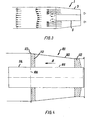
- the diffuser 101 is fitted with an inner tube member 105 projecting out of the outlet tube member 103 beyond the connection flange 113 at which the diffuser 101 is connected with a duct, not shown.
- the length of the projecting downstream end beyond the outer end of the outlet tube member 103 can be chosen in relation to the flow velocity, the fluid and dimensions of the diffuser 101, but will normally be in the range from 0.25 ⁇ D to 1.5 ⁇ D, preferably about 1-D, where D is the diameter of the inner tube member 105.
- the efficiency of the diffuser 101 is improved, and a sketch of the improved velocity profile at the outlet of the diffuser 101 according to the invention can be seen in Fig. 5.
- the recirculating flow is partly contained in the hollow end of the inner tube member 105, so the influence of the recirculating flow on the main flow is greatly reduced.
- a favourable way of acheiving an inner tube member with these characteristics is to fit a known inner tube member with an extension tube element 116 in the downstream end.
- Fig. 6 is perhaps a more illustrative view of the diffuser 1 according to the invention.
- the inner tube member 105 consists of two parts, a base element 115 and an extension tube element 116, so the closing means 106 is set back relative to the end of the extension tube element 116, while the extension tube member 116 in turn projects out of the outlet tube member 103.
- the inner tube member 115 is connected to the outlet tube member 103 by spacers 112, and a duct can be connected to the diffuser 101 at flange 113.
- the closing means 106 of the inner tube member may be placed anywhere along the length of the inner tube, as long as the inner tube is open ended. However it is preferred that the closing means is placed near a position in alignment with the downstream outer end of the outlet tube member or upstream of this.
- the closing means 106 of the inner tube member may take any appropriate form, e.g. a wall, a block, a partition, a plate etc.
- the extension tube element 116 is preferably cylindrical, but may be slightly conical.
Landscapes
- Engineering & Computer Science (AREA)
- Mechanical Engineering (AREA)
- General Engineering & Computer Science (AREA)
- Structures Of Non-Positive Displacement Pumps (AREA)
- Jet Pumps And Other Pumps (AREA)
- Massaging Devices (AREA)
- Compressor (AREA)
- Cooling Or The Like Of Electrical Apparatus (AREA)
Claims (6)
- Luftauslasseinheit (1, 101) für eine große Gebläseanordnung (2), umfassend ein Auslassrohrelement (3, 103) mit einem stromaufwärts gelegenen inneren Ende, welches in einer Strömungsverbindung mit der Druckseite eines Gebläserads (4) der Gebläseanordnung (2) steht, und mit einem stromabwärts gelegenen äußeren Ende für eine Verbindung mit einem Leitungskanal und ein im Wesentlichen zylindrisches inneres Rohrelement (5, 105, 115), koaxial angeordnet zu dem Auslassrohrelement (3, 103) und mit einem inneren Ende, das im Wesentlichen mit dem inneren Ende des Auslassrohrelements (3, 103) ausgerichtet ist, und mit einem stromabwärts gelegenen äußeren Ende, wobei das innere Rohrelement (5, 105, 115) durch ein Schließmittel (6, 106) geschlossen ist, dadurch gekennzeichnet, dass
das innere Rohrelement (5, 105, 115) ein geöffnetes, stromabwärts gelegenes Ende (114, 116) aufweist, das in die Stromabwärtsrichtung über das stromabwärts gelegene äußere Ende des Auslassrohrelements (3, 103) hervorragt. - Luftauslasseinheit nach Anspruch 1, dadurch gekennzeichnet, dass
die Länge des hervorragenden, stromabwärts gelegenen Endes (114, 116) des inneren Rohrelements (5, 105, 115) von dem stromabwärts gelegenen, äußeren Ende des Auslassrohrelements (3, 103) zu dem stromabwärts gelegenen Ende des hervorragenden Endes (114, 116) in dem Bereich von 0,25 D bis 1,5 D, bevorzugt etwa bei 1 D liegt, wobei D der Durchmesser des inneren Rohrelements (5, 105) ist. - Luftauslasseinheit nach Anspruch 1 oder 2, dadurch gekennzeichnet, dass
das innere Rohrelement (5, 105) einen Basisabschnitt (115) und ein Ansatzrohrelement (116) umfasst. - Luftauslasseinheit nach einem der vorherigen Ansprüche, dadurch gekennzeichnet, dass
das Schließmittel (6, 106) des inneren Rohrelements (5, 105, 115) zwischen dem inneren Ende des inneren Rohrs (5, 105, 115) und einer Position, die zu dem stromabwärts gelegenen äußeren Ende des Auslassrohrelements (3, 103) ausgerichtet ist, angeordnet ist. - Luftauslasseinheit nach einem der vorherigen Ansprüche, dadurch gekennzeichnet, dass die Einheit ein Diffusor mit einem Auslassrohrelement (3, 103), welches leicht divergierende Wände in der Stromabwärtsrichtung aufweist, ist.
- Luftauslasseinheit nach einem der Ansprüche 1 bis 4, dadurch gekennzeichnet, dass
die Luftauslasseinheit eine Düse mit einem Auslassrohrelement (3, 103), das leicht konvergierende Wände in der Stromabwärtsrichtung aufweist, ist.
Applications Claiming Priority (1)
| Application Number | Priority Date | Filing Date | Title |
|---|---|---|---|
| PCT/DK2001/000385 WO2002099288A1 (en) | 2001-06-06 | 2001-06-06 | An air outlet unit for a large blower assembly |
Publications (2)
| Publication Number | Publication Date |
|---|---|
| EP1399679A1 EP1399679A1 (de) | 2004-03-24 |
| EP1399679B1 true EP1399679B1 (de) | 2006-10-25 |
Family
ID=8149433
Family Applications (1)
| Application Number | Title | Priority Date | Filing Date |
|---|---|---|---|
| EP01938008A Expired - Lifetime EP1399679B1 (de) | 2001-06-06 | 2001-06-06 | Luftauslasseinheit für grosse gebläseanordnung |
Country Status (9)
| Country | Link |
|---|---|
| US (1) | US7029234B2 (de) |
| EP (1) | EP1399679B1 (de) |
| JP (1) | JP4791691B2 (de) |
| CN (1) | CN1240946C (de) |
| AT (1) | ATE343726T1 (de) |
| CA (1) | CA2449779C (de) |
| DE (1) | DE60124150T2 (de) |
| DK (1) | DK1399679T3 (de) |
| WO (1) | WO2002099288A1 (de) |
Families Citing this family (5)
| Publication number | Priority date | Publication date | Assignee | Title |
|---|---|---|---|---|
| NO328277B1 (no) | 2008-04-21 | 2010-01-18 | Statoil Asa | Gasskompresjonssystem |
| US8979490B2 (en) * | 2011-09-29 | 2015-03-17 | Hamilton Sundstrand Corporation | Fan inlet diffuser housing riveted center body retention |
| US9132919B2 (en) * | 2012-01-11 | 2015-09-15 | Hamilton Sundstrand Corporation | Speed sensor module and diffuser assembly |
| AU2020449612B2 (en) | 2020-05-27 | 2024-06-13 | Howden Netherlands B.V. | Diffuser |
| US12018856B2 (en) * | 2020-08-04 | 2024-06-25 | Nailor Industries Of Texas, Inc. | Dual inlet air diffuser |
Family Cites Families (12)
| Publication number | Priority date | Publication date | Assignee | Title |
|---|---|---|---|---|
| FR891380A (fr) * | 1942-02-28 | 1944-03-06 | Machine soufflante ou pompe parcourue par un courant axial, comportant un diffuseur à âme creuse, accessible de l'extérieur | |
| US2552118A (en) * | 1947-03-27 | 1951-05-08 | Buffalo Turbine Corp | Blower |
| US2637487A (en) * | 1948-03-09 | 1953-05-05 | James G Sawyer | Blower |
| US2814433A (en) | 1954-02-19 | 1957-11-26 | Young Radiator Co | Propeller fan nozzle |
| GB1161186A (en) * | 1968-05-28 | 1969-08-13 | Rolls Royce | A Gas Turbine Ducted Fan Engine. |
| US3471080A (en) * | 1968-06-13 | 1969-10-07 | United Aircraft Corp | Low noise generation fan |
| US3860359A (en) * | 1973-07-30 | 1975-01-14 | Curtiss Wright Corp | Mounting system for gas turbine power unit |
| US3927521A (en) * | 1974-01-16 | 1975-12-23 | Westinghouse Electric Corp | Multicone exhaust diffuser system for a gas turbine |
| JPS52117603U (de) * | 1976-03-03 | 1977-09-06 | ||
| JPS53127308U (de) * | 1977-03-18 | 1978-10-09 | ||
| JP3311526B2 (ja) * | 1994-12-02 | 2002-08-05 | 株式会社日立製作所 | 軸流送風機 |
| WO2001098668A1 (en) * | 2000-06-21 | 2001-12-27 | Howden Power A/S | Guiding arrangement for a large blower unit |
-
2001
- 2001-06-06 WO PCT/DK2001/000385 patent/WO2002099288A1/en not_active Ceased
- 2001-06-06 AT AT01938008T patent/ATE343726T1/de active
- 2001-06-06 JP JP2003502378A patent/JP4791691B2/ja not_active Expired - Lifetime
- 2001-06-06 CA CA002449779A patent/CA2449779C/en not_active Expired - Lifetime
- 2001-06-06 EP EP01938008A patent/EP1399679B1/de not_active Expired - Lifetime
- 2001-06-06 DK DK01938008T patent/DK1399679T3/da active
- 2001-06-06 US US10/479,599 patent/US7029234B2/en not_active Expired - Lifetime
- 2001-06-06 CN CNB018233309A patent/CN1240946C/zh not_active Expired - Lifetime
- 2001-06-06 DE DE60124150T patent/DE60124150T2/de not_active Expired - Lifetime
Also Published As
| Publication number | Publication date |
|---|---|
| CA2449779A1 (en) | 2002-12-12 |
| WO2002099288A1 (en) | 2002-12-12 |
| US7029234B2 (en) | 2006-04-18 |
| JP2004527695A (ja) | 2004-09-09 |
| CA2449779C (en) | 2009-11-03 |
| CN1511233A (zh) | 2004-07-07 |
| DK1399679T3 (da) | 2007-01-22 |
| DE60124150T2 (de) | 2007-08-30 |
| DE60124150D1 (de) | 2006-12-07 |
| ATE343726T1 (de) | 2006-11-15 |
| JP4791691B2 (ja) | 2011-10-12 |
| EP1399679A1 (de) | 2004-03-24 |
| CN1240946C (zh) | 2006-02-08 |
| US20040240993A1 (en) | 2004-12-02 |
Similar Documents
| Publication | Publication Date | Title |
|---|---|---|
| US5462088A (en) | Gas turbine exhaust diffuser | |
| US20200408221A1 (en) | Oblique flow fan | |
| US7029234B2 (en) | Air outlet unit for a large blower assembly | |
| GB2562263A (en) | Bellmouth for jetfan | |
| CN111495227B (zh) | 流动调节系统 | |
| CN110529414A (zh) | 一种离心式管道风机 | |
| KR20180009696A (ko) | 인테이크 사일런서 | |
| US10006469B2 (en) | Diffuser and method of operating diffuser | |
| US20130315729A1 (en) | Upblast Exhaust Apparatus With A Variable Outlet Nozzle | |
| KR20190044756A (ko) | 환풍장치 | |
| US20070036648A1 (en) | Extended venturi fan ring | |
| JPH06178419A (ja) | コアンダフロー通線装置 | |
| CN113795716B (zh) | 流体排放管道组件 | |
| RU2851560C1 (ru) | Система проветривания протяженных тупиковых выработок | |
| WO2001098668A1 (en) | Guiding arrangement for a large blower unit | |
| CN223324757U (zh) | 粉料喷枪和粉料喷射装置 | |
| CN108252955B (zh) | 压气机用管式扩压器 | |
| CN216477546U (zh) | 一种排气管加速结构及真空泵 | |
| CN222131441U (zh) | 一种可调流量的喷射器 | |
| RU2235221C1 (ru) | Диаметральный вентилятор | |
| RU2666683C2 (ru) | Плоскощелевой эжектор | |
| KR20240041738A (ko) | 유해가스 급속배기 유도장치 | |
| CN121976881A (zh) | 用于航空发动机进气道的引射装置、进气道及航空发动机 | |
| KR20160101483A (ko) | 유체 흡입장치 | |
| SU1681971A1 (ru) | Выпускное устройство |
Legal Events
| Date | Code | Title | Description |
|---|---|---|---|
| PUAI | Public reference made under article 153(3) epc to a published international application that has entered the european phase |
Free format text: ORIGINAL CODE: 0009012 |
|
| 17P | Request for examination filed |
Effective date: 20031216 |
|
| AK | Designated contracting states |
Kind code of ref document: A1 Designated state(s): AT BE CH CY DE DK ES FI FR GB GR IE IT LI LU MC NL PT SE TR |
|
| AX | Request for extension of the european patent |
Extension state: AL LT LV MK RO SI |
|
| GRAP | Despatch of communication of intention to grant a patent |
Free format text: ORIGINAL CODE: EPIDOSNIGR1 |
|
| GRAC | Information related to communication of intention to grant a patent modified |
Free format text: ORIGINAL CODE: EPIDOSCIGR1 |
|
| RIC1 | Information provided on ipc code assigned before grant |
Ipc: F04D 29/54 20060101ALI20060412BHEP Ipc: F04D 29/44 20060101AFI20060412BHEP |
|
| RIN1 | Information on inventor provided before grant (corrected) |
Inventor name: JENSEN, ERLING |
|
| GRAS | Grant fee paid |
Free format text: ORIGINAL CODE: EPIDOSNIGR3 |
|
| GRAA | (expected) grant |
Free format text: ORIGINAL CODE: 0009210 |
|
| AK | Designated contracting states |
Kind code of ref document: B1 Designated state(s): AT BE CH CY DE DK ES FI FR GB GR IE IT LI LU MC NL PT SE TR |
|
| PG25 | Lapsed in a contracting state [announced via postgrant information from national office to epo] |
Ref country code: BE Free format text: LAPSE BECAUSE OF FAILURE TO SUBMIT A TRANSLATION OF THE DESCRIPTION OR TO PAY THE FEE WITHIN THE PRESCRIBED TIME-LIMIT Effective date: 20061025 Ref country code: NL Free format text: LAPSE BECAUSE OF FAILURE TO SUBMIT A TRANSLATION OF THE DESCRIPTION OR TO PAY THE FEE WITHIN THE PRESCRIBED TIME-LIMIT Effective date: 20061025 Ref country code: FI Free format text: LAPSE BECAUSE OF FAILURE TO SUBMIT A TRANSLATION OF THE DESCRIPTION OR TO PAY THE FEE WITHIN THE PRESCRIBED TIME-LIMIT Effective date: 20061025 |
|
| REG | Reference to a national code |
Ref country code: GB Ref legal event code: FG4D |
|
| REG | Reference to a national code |
Ref country code: CH Ref legal event code: EP |
|
| REG | Reference to a national code |
Ref country code: IE Ref legal event code: FG4D |
|
| REF | Corresponds to: |
Ref document number: 60124150 Country of ref document: DE Date of ref document: 20061207 Kind code of ref document: P |
|
| REG | Reference to a national code |
Ref country code: CH Ref legal event code: NV Representative=s name: A. BRAUN, BRAUN, HERITIER, ESCHMANN AG PATENTANWAE |
|
| REG | Reference to a national code |
Ref country code: DK Ref legal event code: T3 |
|
| PG25 | Lapsed in a contracting state [announced via postgrant information from national office to epo] |
Ref country code: SE Free format text: LAPSE BECAUSE OF FAILURE TO SUBMIT A TRANSLATION OF THE DESCRIPTION OR TO PAY THE FEE WITHIN THE PRESCRIBED TIME-LIMIT Effective date: 20070125 |
|
| PG25 | Lapsed in a contracting state [announced via postgrant information from national office to epo] |
Ref country code: ES Free format text: LAPSE BECAUSE OF FAILURE TO SUBMIT A TRANSLATION OF THE DESCRIPTION OR TO PAY THE FEE WITHIN THE PRESCRIBED TIME-LIMIT Effective date: 20070205 |
|
| PG25 | Lapsed in a contracting state [announced via postgrant information from national office to epo] |
Ref country code: PT Free format text: LAPSE BECAUSE OF FAILURE TO SUBMIT A TRANSLATION OF THE DESCRIPTION OR TO PAY THE FEE WITHIN THE PRESCRIBED TIME-LIMIT Effective date: 20070326 |
|
| NLV1 | Nl: lapsed or annulled due to failure to fulfill the requirements of art. 29p and 29m of the patents act | ||
| ET | Fr: translation filed | ||
| PLBE | No opposition filed within time limit |
Free format text: ORIGINAL CODE: 0009261 |
|
| STAA | Information on the status of an ep patent application or granted ep patent |
Free format text: STATUS: NO OPPOSITION FILED WITHIN TIME LIMIT |
|
| 26N | No opposition filed |
Effective date: 20070726 |
|
| PG25 | Lapsed in a contracting state [announced via postgrant information from national office to epo] |
Ref country code: MC Free format text: LAPSE BECAUSE OF NON-PAYMENT OF DUE FEES Effective date: 20070630 |
|
| PG25 | Lapsed in a contracting state [announced via postgrant information from national office to epo] |
Ref country code: GR Free format text: LAPSE BECAUSE OF FAILURE TO SUBMIT A TRANSLATION OF THE DESCRIPTION OR TO PAY THE FEE WITHIN THE PRESCRIBED TIME-LIMIT Effective date: 20070126 |
|
| PG25 | Lapsed in a contracting state [announced via postgrant information from national office to epo] |
Ref country code: IE Free format text: LAPSE BECAUSE OF NON-PAYMENT OF DUE FEES Effective date: 20070606 |
|
| REG | Reference to a national code |
Ref country code: CH Ref legal event code: PFA Owner name: HOWDEN POWER A/S Free format text: HOWDEN POWER A/S#INDUSTRIVEJ 17-21#4700 NAESTVED (DK) -TRANSFER TO- HOWDEN POWER A/S#INDUSTRIVEJ 17-21#4700 NAESTVED (DK) |
|
| PG25 | Lapsed in a contracting state [announced via postgrant information from national office to epo] |
Ref country code: LU Free format text: LAPSE BECAUSE OF NON-PAYMENT OF DUE FEES Effective date: 20070606 Ref country code: CY Free format text: LAPSE BECAUSE OF FAILURE TO SUBMIT A TRANSLATION OF THE DESCRIPTION OR TO PAY THE FEE WITHIN THE PRESCRIBED TIME-LIMIT Effective date: 20061025 |
|
| PG25 | Lapsed in a contracting state [announced via postgrant information from national office to epo] |
Ref country code: TR Free format text: LAPSE BECAUSE OF FAILURE TO SUBMIT A TRANSLATION OF THE DESCRIPTION OR TO PAY THE FEE WITHIN THE PRESCRIBED TIME-LIMIT Effective date: 20061025 |
|
| REG | Reference to a national code |
Ref country code: CH Ref legal event code: PCAR Free format text: NEW ADDRESS: HOLBEINSTRASSE 36-38, 4051 BASEL (CH) |
|
| REG | Reference to a national code |
Ref country code: FR Ref legal event code: PLFP Year of fee payment: 16 |
|
| REG | Reference to a national code |
Ref country code: FR Ref legal event code: PLFP Year of fee payment: 17 |
|
| REG | Reference to a national code |
Ref country code: FR Ref legal event code: PLFP Year of fee payment: 18 |
|
| PGFP | Annual fee paid to national office [announced via postgrant information from national office to epo] |
Ref country code: DK Payment date: 20200629 Year of fee payment: 20 Ref country code: DE Payment date: 20200629 Year of fee payment: 20 Ref country code: FR Payment date: 20200625 Year of fee payment: 20 |
|
| PGFP | Annual fee paid to national office [announced via postgrant information from national office to epo] |
Ref country code: IT Payment date: 20200619 Year of fee payment: 20 Ref country code: GB Payment date: 20200629 Year of fee payment: 20 |
|
| PGFP | Annual fee paid to national office [announced via postgrant information from national office to epo] |
Ref country code: AT Payment date: 20200520 Year of fee payment: 20 |
|
| PGFP | Annual fee paid to national office [announced via postgrant information from national office to epo] |
Ref country code: CH Payment date: 20200702 Year of fee payment: 20 |
|
| REG | Reference to a national code |
Ref country code: DE Ref legal event code: R071 Ref document number: 60124150 Country of ref document: DE |
|
| REG | Reference to a national code |
Ref country code: DK Ref legal event code: EUP Expiry date: 20210606 |
|
| REG | Reference to a national code |
Ref country code: CH Ref legal event code: PL |
|
| REG | Reference to a national code |
Ref country code: GB Ref legal event code: PE20 Expiry date: 20210605 |
|
| REG | Reference to a national code |
Ref country code: AT Ref legal event code: MK07 Ref document number: 343726 Country of ref document: AT Kind code of ref document: T Effective date: 20210606 |
|
| PG25 | Lapsed in a contracting state [announced via postgrant information from national office to epo] |
Ref country code: GB Free format text: LAPSE BECAUSE OF EXPIRATION OF PROTECTION Effective date: 20210605 |
|
| P01 | Opt-out of the competence of the unified patent court (upc) registered |
Effective date: 20230531 |