EP1399240B1 - Filterelement mit drainagerohr - Google Patents
Filterelement mit drainagerohr Download PDFInfo
- Publication number
- EP1399240B1 EP1399240B1 EP02780904A EP02780904A EP1399240B1 EP 1399240 B1 EP1399240 B1 EP 1399240B1 EP 02780904 A EP02780904 A EP 02780904A EP 02780904 A EP02780904 A EP 02780904A EP 1399240 B1 EP1399240 B1 EP 1399240B1
- Authority
- EP
- European Patent Office
- Prior art keywords
- filter element
- drainage tube
- connector
- drainage
- filter
- Prior art date
- Legal status (The legal status is an assumption and is not a legal conclusion. Google has not performed a legal analysis and makes no representation as to the accuracy of the status listed.)
- Expired - Lifetime
Links
- 239000012530 fluid Substances 0.000 claims description 7
- 239000007788 liquid Substances 0.000 claims description 7
- 238000004519 manufacturing process Methods 0.000 abstract description 3
- 238000010276 construction Methods 0.000 abstract 1
- 239000007789 gas Substances 0.000 description 4
- 210000001331 nose Anatomy 0.000 description 3
- 238000001746 injection moulding Methods 0.000 description 2
- 238000000034 method Methods 0.000 description 2
- 238000007789 sealing Methods 0.000 description 2
- 239000011265 semifinished product Substances 0.000 description 2
- 239000000853 adhesive Substances 0.000 description 1
- 238000004026 adhesive bonding Methods 0.000 description 1
- 230000001070 adhesive effect Effects 0.000 description 1
- 238000002485 combustion reaction Methods 0.000 description 1
- 238000001125 extrusion Methods 0.000 description 1
- 230000002349 favourable effect Effects 0.000 description 1
- 239000000463 material Substances 0.000 description 1
- 238000000926 separation method Methods 0.000 description 1
Images

Classifications
-
- F—MECHANICAL ENGINEERING; LIGHTING; HEATING; WEAPONS; BLASTING
- F16—ENGINEERING ELEMENTS AND UNITS; GENERAL MEASURES FOR PRODUCING AND MAINTAINING EFFECTIVE FUNCTIONING OF MACHINES OR INSTALLATIONS; THERMAL INSULATION IN GENERAL
- F16N—LUBRICATING
- F16N39/00—Arrangements for conditioning of lubricants in the lubricating system
- F16N39/06—Arrangements for conditioning of lubricants in the lubricating system by filtration
-
- B—PERFORMING OPERATIONS; TRANSPORTING
- B01—PHYSICAL OR CHEMICAL PROCESSES OR APPARATUS IN GENERAL
- B01D—SEPARATION
- B01D46/00—Filters or filtering processes specially modified for separating dispersed particles from gases or vapours
- B01D46/0027—Filters or filtering processes specially modified for separating dispersed particles from gases or vapours with additional separating or treating functions
- B01D46/003—Filters or filtering processes specially modified for separating dispersed particles from gases or vapours with additional separating or treating functions including coalescing means for the separation of liquid
- B01D46/0031—Filters or filtering processes specially modified for separating dispersed particles from gases or vapours with additional separating or treating functions including coalescing means for the separation of liquid with collecting, draining means
-
- B—PERFORMING OPERATIONS; TRANSPORTING
- B01—PHYSICAL OR CHEMICAL PROCESSES OR APPARATUS IN GENERAL
- B01D—SEPARATION
- B01D46/00—Filters or filtering processes specially modified for separating dispersed particles from gases or vapours
- B01D46/24—Particle separators, e.g. dust precipitators, using rigid hollow filter bodies
- B01D46/2403—Particle separators, e.g. dust precipitators, using rigid hollow filter bodies characterised by the physical shape or structure of the filtering element
- B01D46/2407—Filter candles
-
- F—MECHANICAL ENGINEERING; LIGHTING; HEATING; WEAPONS; BLASTING
- F16—ENGINEERING ELEMENTS AND UNITS; GENERAL MEASURES FOR PRODUCING AND MAINTAINING EFFECTIVE FUNCTIONING OF MACHINES OR INSTALLATIONS; THERMAL INSULATION IN GENERAL
- F16N—LUBRICATING
- F16N39/00—Arrangements for conditioning of lubricants in the lubricating system
- F16N39/002—Arrangements for conditioning of lubricants in the lubricating system by deaeration
-
- B—PERFORMING OPERATIONS; TRANSPORTING
- B01—PHYSICAL OR CHEMICAL PROCESSES OR APPARATUS IN GENERAL
- B01D—SEPARATION
- B01D2271/00—Sealings for filters specially adapted for separating dispersed particles from gases or vapours
- B01D2271/02—Gaskets, sealings
- B01D2271/022—Axial sealings
-
- F—MECHANICAL ENGINEERING; LIGHTING; HEATING; WEAPONS; BLASTING
- F01—MACHINES OR ENGINES IN GENERAL; ENGINE PLANTS IN GENERAL; STEAM ENGINES
- F01M—LUBRICATING OF MACHINES OR ENGINES IN GENERAL; LUBRICATING INTERNAL COMBUSTION ENGINES; CRANKCASE VENTILATING
- F01M13/00—Crankcase ventilating or breathing
- F01M13/04—Crankcase ventilating or breathing having means for purifying air before leaving crankcase, e.g. removing oil
- F01M2013/0438—Crankcase ventilating or breathing having means for purifying air before leaving crankcase, e.g. removing oil with a filter
-
- Y—GENERAL TAGGING OF NEW TECHNOLOGICAL DEVELOPMENTS; GENERAL TAGGING OF CROSS-SECTIONAL TECHNOLOGIES SPANNING OVER SEVERAL SECTIONS OF THE IPC; TECHNICAL SUBJECTS COVERED BY FORMER USPC CROSS-REFERENCE ART COLLECTIONS [XRACs] AND DIGESTS
- Y10—TECHNICAL SUBJECTS COVERED BY FORMER USPC
- Y10S—TECHNICAL SUBJECTS COVERED BY FORMER USPC CROSS-REFERENCE ART COLLECTIONS [XRACs] AND DIGESTS
- Y10S55/00—Gas separation
- Y10S55/17—Compressed air water removal
Definitions
- the invention relates to a filter element, in particular a Beerentölelement, for the separation of a liquid with a drainage pipe through which the deposited liquid can be removed, according to the preamble of claim 1.
- a drainage device containing the drainage tube and a filter device is provided under protection.
- Filter elements according to the preamble are generally accessible prior art (see JP 07217577 ). They are used for example for de-oiling compressed air in compressed air systems, which are fed by an oil-lubricated compressor. Another application is the de-oiling of crankcase gases of an internal combustion engine.
- the deposited liquid collects inside the filter cartridge, which is preferably cylindrical. From there it is sucked off with the help of a drainage tube, which extends into the interior of the filter cartridge.
- This drainage tube may be an integral part of the upper end plate of the filter element, so that a fixation in the position necessary for the suction is possible.
- a filter element with fixed drainage pipe is cumbersome to manufacture, which is why the filter element is less economical.
- the object of the invention is therefore to provide a filter element with drainage pipe, which is inexpensive to manufacture. This object is solved by the features of claim 1.
- the filter element according to the invention is characterized in that the drainage tube can be fixed by means of a connector in the upper end plate. Drainage pipe and connector together form the drainage device, which as a separate component can be produced.
- the connection with the end plate is preferably carried out releasably, whereby the drainage pipe can be removed when changing the filter element and inserted into the new filter element.
- the spare parts can be produced more cost-effectively, since the drainage device can be used multiple times.
- the drainage device itself may be a standard component, which is equipped according to a particular embodiment of the invention with snap lugs as a connector. These can be produced in one piece, for example, in plastic, which is why the drainage device can be produced inexpensively. Corresponding receptacles for the connectors in the end plate can also be realized in the design as snap lugs also simply by, for example, window-shaped openings.
- the designation of the connecting elements on the drainage pipe and on the end disk of the filter element should not be understood as a restriction that snap-nose-shaped components can only be provided on the drainage pipe.
- the snap noses may also be referred to as a receptacle, the connector then being a corresponding means for holding the snap noses on the drainage device.
- the drainage pipe can be made in one piece with the connector.
- This one-piece drainage device can then be produced inexpensively, for example by means of the injection molding process in plastic.
- the connector is provided with a pipe socket which forms a part of the drainage pipe, but on the other hand allows a plug connection with the actual drainage pipe.
- the base component which must be produced for example by injection molding due to its geometric structure, then consists of the connector with the pipe socket. This can be used for all sizes of filter elements, as by adapting the length of the associated drainage pipe an application can be made to all applications.
- the drainage pipe itself consists of a semi-finished product, namely a pipe, which can be obtained for example by extrusion. This is therefore an exceptionally favorable component.
- the costs for warehousing can be reduced by a few basic components for all variants.
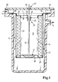
- the filter device according to FIG. 1 has a housing 11 with a cover 12, wherein an inlet 13 and an outlet 14 for the fluid to be filtered, in particular a gas, are formed by the housing. Between housing 11 and cover 12, a filter element 15 is held with an upper end plate 16 by means of a clamping connection. The filter element 15 also has a support body 17 and a lower end plate 18.
- the path of the gas to be filtered is indicated by arrows. It extends from the inlet 13 through openings, not shown, in the upper end disk 16 into an interior 19 of the filter element 15, from where the gas stream is passed through a filter medium 20 and the likewise permeable support body 17 to the outlet 14. In this case, the deposited liquid collects in a recess 21 of the lower end plate 18, which can be sucked out of the inner space 19 through a drainage pipe 22.
- the drainage tube 22 is part of a drainage device 23, which among other things also has a connector 24 with snap-in lugs 25.
- the connector is thus designed as a plug-shaped component, which in a hole-shaped receptacle 26 in the end plate can be plugged.
- the connector is placed on the drainage pipe 22 and glued to it.
- a sealing of the filter medium is carried out by gluing of its end faces 29 in corresponding paragraphs of the upper and lower end plate 16, 18th
- FIG. 2 shows an alternative embodiment of the drainage device 23.
- the connector 24 has a pipe extension 30, which, according to the drainage pipe according to FIG. 1, serves as a connection, for example, to a hose for sucking off the separated liquid.
- This connector is to be understood as a basic component and can be used for filter elements of different dimensions.
- a connector 31 is realized on the connector, with the aid of which the actual drainage pipe 22a can be connected to the connector.
- the drainage pipe 22a consists of a standard semi-finished product in the form of a tube and is deflected by this. In this way, the length of the drainage tube is freely selectable and optimally adapted to the current application.
- FIG. 1 An upper end plate 16, which can receive the drainage device 23, is shown in FIG. Evident is a web 32, which spans a passage opening 33 for the fluid to be filtered (the one which is not shown in FIG. 1).
- the drainage device 23 can be inserted into a central bore 40.
- Window-shaped receptacles 26 serve to fix the snap-in lugs 25 according to FIG. 2.
- the snap-in lugs 25 and the associated receptacles 26 four are arranged in series. As a result, a reliable fixation can be achieved. In addition, a reliable mounting of the drainage device is still possible if one of the snap noses should stop.
- connection method for the snap connection shown in Figures 1 and 2 of course, other connection methods are conceivable.
- the same materials of the drainage device and the end plate can be, for example, a welded joint think.
- Another possibility is an adhesive bond.
- other connectors may be used to make releasable connections, such as nuts and screws, instead of the snap tabs.
- a riveted connection is also conceivable.
- the possibility of a frictional or non-positive connection may be mentioned, for example by a press fit. As a result, a seal can be achieved.
Landscapes
- Engineering & Computer Science (AREA)
- General Engineering & Computer Science (AREA)
- Chemical & Material Sciences (AREA)
- Chemical Kinetics & Catalysis (AREA)
- Mechanical Engineering (AREA)
- Geometry (AREA)
- Physics & Mathematics (AREA)
- Lubrication Details And Ventilation Of Internal Combustion Engines (AREA)
- Filtering Of Dispersed Particles In Gases (AREA)
- Compressor (AREA)
- Sink And Installation For Waste Water (AREA)
- Centrifugal Separators (AREA)
- Filtration Of Liquid (AREA)
Applications Claiming Priority (3)
| Application Number | Priority Date | Filing Date | Title |
|---|---|---|---|
| DE10131108A DE10131108A1 (de) | 2001-06-27 | 2001-06-27 | Filterelement mit Drainagerohr |
| DE10131108 | 2001-06-27 | ||
| PCT/EP2002/006710 WO2003002233A2 (de) | 2001-06-27 | 2002-06-18 | Filterelement mit drainagerohr |
Publications (2)
| Publication Number | Publication Date |
|---|---|
| EP1399240A2 EP1399240A2 (de) | 2004-03-24 |
| EP1399240B1 true EP1399240B1 (de) | 2007-08-22 |
Family
ID=7689715
Family Applications (1)
| Application Number | Title | Priority Date | Filing Date |
|---|---|---|---|
| EP02780904A Expired - Lifetime EP1399240B1 (de) | 2001-06-27 | 2002-06-18 | Filterelement mit drainagerohr |
Country Status (7)
| Country | Link |
|---|---|
| US (1) | US7097683B2 (enExample) |
| EP (1) | EP1399240B1 (enExample) |
| JP (1) | JP4220376B2 (enExample) |
| CN (1) | CN1304087C (enExample) |
| AT (1) | ATE370782T1 (enExample) |
| DE (2) | DE10131108A1 (enExample) |
| WO (1) | WO2003002233A2 (enExample) |
Families Citing this family (18)
| Publication number | Priority date | Publication date | Assignee | Title |
|---|---|---|---|---|
| GB0417462D0 (en) * | 2004-08-05 | 2004-09-08 | Domnick Hunter Ltd | Filter element |
| KR200371804Y1 (ko) * | 2004-10-11 | 2005-01-06 | 한국뉴매틱(주) | 에어 필터 장치 |
| EP1695753B1 (de) | 2005-02-28 | 2014-06-04 | MANN+HUMMEL GmbH | Filterelement mit Drainagerohr |
| DE202005014125U1 (de) * | 2005-09-08 | 2007-01-25 | Mann + Hummel Gmbh | Abscheider zur Reinigung eines Fluidstromes |
| DE102006017635A1 (de) * | 2006-04-12 | 2007-10-18 | Mann + Hummel Gmbh | Mehrstufige Vorrichtung zum Abscheiden von Flüssigkeitstropfen aus Gasen |
| DE202006006084U1 (de) * | 2006-04-12 | 2007-08-16 | Mann + Hummel Gmbh | Mehrstufige Vorrichtung zum Abscheiden von Flüssigkeitstropfen aus Gasen |
| US7905947B2 (en) * | 2006-05-24 | 2011-03-15 | L.C. Eldridge Sales Co., Ltd. | Method and apparatus for removing contaminates from air |
| CN101314096B (zh) * | 2007-05-29 | 2012-09-26 | 威埃姆输送机械(上海)有限公司 | 管状除尘过滤装置 |
| DE102007041733B4 (de) * | 2007-09-04 | 2009-09-03 | Hüttlin Gmbh | Filteranordnung zum Reinigen von mit Partikeln verunreinigten Gasen und Verfahren zum Reinigen mindestens einer Filtereinheit |
| DE202007015034U1 (de) * | 2007-10-26 | 2009-03-05 | Mann+Hummel Gmbh | Vorrichtung zur Abscheidung von Flüssigkeitstropfen aus einem Gasstrom |
| DE102011009926A1 (de) * | 2011-01-31 | 2012-08-02 | Mann + Hummel Gmbh | Filtersystem für Motoröl einer Brennkraftmaschine und Wechselfilter eines Filtersystems |
| WO2014151932A1 (en) * | 2013-03-15 | 2014-09-25 | Donaldson Company, Inc. | Scavenge tube arrangement; gas liquid separator filter assembly; and methods |
| DE102014002719B4 (de) * | 2013-05-15 | 2017-10-12 | Mann + Hummel Gmbh | Abscheideelement und Flüssigkeitsabscheider zur Abscheidung von Flüssigkeiten aus einem Gasstrom |
| WO2016143107A1 (ja) * | 2015-03-12 | 2016-09-15 | 東京濾器株式会社 | オイルミストフィルタ及びオイルセパレータ |
| CN104948468B (zh) * | 2015-07-07 | 2017-08-15 | 无锡压缩机股份有限公司 | 油气分离器滤芯底部回油装置 |
| DE102018123413B4 (de) * | 2017-10-06 | 2024-12-12 | Mann+Hummel Gmbh | Filtereinsatz und Vorrichtung zum Abscheiden von Ölaerosol aus Luft |
| DE102017011691B4 (de) | 2017-12-18 | 2025-12-04 | Mann+Hummel Gmbh | Flüssigkeitsabscheider |
| CN111437662B (zh) * | 2020-05-22 | 2021-09-03 | 重庆开山流体机械有限公司 | 一种油气分离检测装置 |
Family Cites Families (10)
| Publication number | Priority date | Publication date | Assignee | Title |
|---|---|---|---|---|
| US2934166A (en) * | 1956-05-08 | 1960-04-26 | Shell Oil Co | Gas-demisting apparatus with drained mat |
| GB8703314D0 (en) * | 1987-02-13 | 1987-03-18 | Process Scient Innovations | Air/oil separator |
| CN2096648U (zh) * | 1991-07-23 | 1992-02-19 | 长沙汽车发动机总厂 | 汽油机油气分离室 |
| JP3559582B2 (ja) * | 1994-02-01 | 2004-09-02 | 株式会社日立産機システム | 油冷式圧縮機の油分離エレメント |
| DE4429822C2 (de) * | 1994-08-23 | 1998-02-19 | Mann & Hummel Filter | Vorrichtung zum Abscheiden von Ölaerosol aus Luft |
| JPH0972635A (ja) * | 1995-09-04 | 1997-03-18 | Izumi Giken:Kk | オイルセパレータ |
| US5788859A (en) * | 1996-05-10 | 1998-08-04 | Baldwin Filters, Inc. | Self-evacuating water-separating fuel filter |
| US5899667A (en) * | 1997-04-10 | 1999-05-04 | Ingersoll-Rand Company | Fluid compressor with seal scavenge and method |
| CN2352700Y (zh) * | 1998-12-30 | 1999-12-08 | 李建新 | 化油器节能净化装置 |
| US6409804B1 (en) * | 2000-09-29 | 2002-06-25 | Ingersoll-Rand Company | Separator tank assembly for a fluid compressor |
-
2001
- 2001-06-27 DE DE10131108A patent/DE10131108A1/de not_active Withdrawn
-
2002
- 2002-06-18 EP EP02780904A patent/EP1399240B1/de not_active Expired - Lifetime
- 2002-06-18 CN CNB028167139A patent/CN1304087C/zh not_active Expired - Lifetime
- 2002-06-18 DE DE50210763T patent/DE50210763D1/de not_active Expired - Lifetime
- 2002-06-18 JP JP2003508460A patent/JP4220376B2/ja not_active Expired - Fee Related
- 2002-06-18 WO PCT/EP2002/006710 patent/WO2003002233A2/de not_active Ceased
- 2002-06-18 AT AT02780904T patent/ATE370782T1/de not_active IP Right Cessation
-
2003
- 2003-12-29 US US10/746,146 patent/US7097683B2/en not_active Expired - Lifetime
Also Published As
| Publication number | Publication date |
|---|---|
| JP4220376B2 (ja) | 2009-02-04 |
| DE10131108A1 (de) | 2003-01-09 |
| EP1399240A2 (de) | 2004-03-24 |
| ATE370782T1 (de) | 2007-09-15 |
| US20050044827A1 (en) | 2005-03-03 |
| CN1551793A (zh) | 2004-12-01 |
| DE50210763D1 (de) | 2007-10-04 |
| CN1304087C (zh) | 2007-03-14 |
| US7097683B2 (en) | 2006-08-29 |
| WO2003002233A2 (de) | 2003-01-09 |
| WO2003002233A3 (de) | 2003-09-18 |
| JP2004538133A (ja) | 2004-12-24 |
Similar Documents
| Publication | Publication Date | Title |
|---|---|---|
| EP1399240B1 (de) | Filterelement mit drainagerohr | |
| EP1695753B1 (de) | Filterelement mit Drainagerohr | |
| DE602005002948T2 (de) | Filterelement mit ausseraxialer abschlusskappe | |
| EP2982427B1 (de) | Gehäuse und einrichtung zur abscheidung eines fluids | |
| EP1685889B1 (de) | Filter für Ölwanne | |
| DE102014006853B4 (de) | Hohlfilterelement, Filtergehäuse und Filter | |
| EP3473322B1 (de) | Becherförmiges gehäuse, vorrichtung zum abscheiden von flüssigkeit aus luft sowie verfahren zur montage des becherförmigen gehäuses auf einen nippel | |
| EP0695572A2 (de) | Ölabscheider | |
| EP0951329A1 (de) | Filter, insbesondere für das schmieröl einer brennkraftmaschine | |
| EP3641909B1 (de) | Filtersystem mit filterelement und sekundärelement zum verschliesen eines mittelrohrs | |
| WO2014121990A1 (de) | Filtereinrichtung, insbesondere luftfilter | |
| EP2538065A1 (de) | Kraftstoffzuführeinrichtung, insbesondere für eine Brennkraftmaschine | |
| EP3408009A1 (de) | Gehäuse, fluidauslass-dichtungsteil, gehäusedeckel und verbindungsteil einer einrichtung zur abscheidung wenigstens eines fluids aus gas und einrichtung und vorrichtung zur abscheidung eines fluids | |
| EP3067102B1 (de) | Wasserabscheider und wasserabscheidesystem mit integrierter wasseraustragseinrichtung | |
| EP3390185A1 (de) | Lufttrocknerpatrone | |
| DE102011108061A1 (de) | Fluidfilteranordnung und Filterverfahren | |
| DE102018123413A1 (de) | Flansch, Filtereinsatz, Vorrichtung zum Abscheiden von Ölaerosol aus Luft sowie Verfahren zur Herstellung eines Filtereinsatzes | |
| DE102019128397A1 (de) | Abscheidevorrichtung zur Abscheidung von Flüssigkeit aus Gas, insbesondere Luft, und Abscheidesystem einer Maschine | |
| DE102011018715A1 (de) | Luftfilterelement und Gehäuse für ein Luftfilterelement | |
| DE102016000339B4 (de) | Filterelement und Filtersystem für ein Flüssigmedium mit rein- und rohseitiger Entlüftung | |
| EP2478949B1 (de) | Vorrichtung zum Abscheiden von in gasförmigen Medien enthaltenen Fluiden, insbesondere öl aus Gaskraftstoffen für Verbrennungsmotoren | |
| DE10240666B4 (de) | Flüssigkeitsfilter, insbesondere für Getriebeöl in Kraftfahrzeugen | |
| WO2019024991A1 (de) | Gehäuse, fluidauslass-dichtungsteil, gehäusedeckel und verbindungsteil einer einrichtung zur abscheidung wenigstens eines fluids aus gas und einrichtung und vorrichtung zur abscheidung eines fluids | |
| DE202006002383U1 (de) | Filterelement mit Drainagerohr | |
| DE202008016624U1 (de) | Filtereinrichtung für Kraftstoff |
Legal Events
| Date | Code | Title | Description |
|---|---|---|---|
| PUAI | Public reference made under article 153(3) epc to a published international application that has entered the european phase |
Free format text: ORIGINAL CODE: 0009012 |
|
| 17P | Request for examination filed |
Effective date: 20031229 |
|
| AK | Designated contracting states |
Kind code of ref document: A2 Designated state(s): AT BE CH CY DE DK ES FI FR GB GR IE IT LI LU MC NL PT SE TR |
|
| GRAP | Despatch of communication of intention to grant a patent |
Free format text: ORIGINAL CODE: EPIDOSNIGR1 |
|
| GRAS | Grant fee paid |
Free format text: ORIGINAL CODE: EPIDOSNIGR3 |
|
| GRAA | (expected) grant |
Free format text: ORIGINAL CODE: 0009210 |
|
| AK | Designated contracting states |
Kind code of ref document: B1 Designated state(s): AT BE CH CY DE DK ES FI FR GB GR IE IT LI LU MC NL PT SE TR |
|
| REG | Reference to a national code |
Ref country code: GB Ref legal event code: FG4D Free format text: NOT ENGLISH |
|
| REG | Reference to a national code |
Ref country code: CH Ref legal event code: EP |
|
| REG | Reference to a national code |
Ref country code: IE Ref legal event code: FG4D Free format text: LANGUAGE OF EP DOCUMENT: GERMAN |
|
| REF | Corresponds to: |
Ref document number: 50210763 Country of ref document: DE Date of ref document: 20071004 Kind code of ref document: P |
|
| PG25 | Lapsed in a contracting state [announced via postgrant information from national office to epo] |
Ref country code: NL Free format text: LAPSE BECAUSE OF FAILURE TO SUBMIT A TRANSLATION OF THE DESCRIPTION OR TO PAY THE FEE WITHIN THE PRESCRIBED TIME-LIMIT Effective date: 20070822 Ref country code: FI Free format text: LAPSE BECAUSE OF FAILURE TO SUBMIT A TRANSLATION OF THE DESCRIPTION OR TO PAY THE FEE WITHIN THE PRESCRIBED TIME-LIMIT Effective date: 20070822 Ref country code: ES Free format text: LAPSE BECAUSE OF FAILURE TO SUBMIT A TRANSLATION OF THE DESCRIPTION OR TO PAY THE FEE WITHIN THE PRESCRIBED TIME-LIMIT Effective date: 20071203 |
|
| NLV1 | Nl: lapsed or annulled due to failure to fulfill the requirements of art. 29p and 29m of the patents act | ||
| GBV | Gb: ep patent (uk) treated as always having been void in accordance with gb section 77(7)/1977 [no translation filed] |
Effective date: 20070822 |
|
| REG | Reference to a national code |
Ref country code: IE Ref legal event code: FD4D |
|
| ET | Fr: translation filed | ||
| PG25 | Lapsed in a contracting state [announced via postgrant information from national office to epo] |
Ref country code: DK Free format text: LAPSE BECAUSE OF FAILURE TO SUBMIT A TRANSLATION OF THE DESCRIPTION OR TO PAY THE FEE WITHIN THE PRESCRIBED TIME-LIMIT Effective date: 20070822 Ref country code: GR Free format text: LAPSE BECAUSE OF FAILURE TO SUBMIT A TRANSLATION OF THE DESCRIPTION OR TO PAY THE FEE WITHIN THE PRESCRIBED TIME-LIMIT Effective date: 20071123 |
|
| PG25 | Lapsed in a contracting state [announced via postgrant information from national office to epo] |
Ref country code: PT Free format text: LAPSE BECAUSE OF FAILURE TO SUBMIT A TRANSLATION OF THE DESCRIPTION OR TO PAY THE FEE WITHIN THE PRESCRIBED TIME-LIMIT Effective date: 20080122 Ref country code: IE Free format text: LAPSE BECAUSE OF FAILURE TO SUBMIT A TRANSLATION OF THE DESCRIPTION OR TO PAY THE FEE WITHIN THE PRESCRIBED TIME-LIMIT Effective date: 20070822 Ref country code: GB Free format text: LAPSE BECAUSE OF FAILURE TO SUBMIT A TRANSLATION OF THE DESCRIPTION OR TO PAY THE FEE WITHIN THE PRESCRIBED TIME-LIMIT Effective date: 20070822 |
|
| PLBE | No opposition filed within time limit |
Free format text: ORIGINAL CODE: 0009261 |
|
| STAA | Information on the status of an ep patent application or granted ep patent |
Free format text: STATUS: NO OPPOSITION FILED WITHIN TIME LIMIT |
|
| PG25 | Lapsed in a contracting state [announced via postgrant information from national office to epo] |
Ref country code: SE Free format text: LAPSE BECAUSE OF FAILURE TO SUBMIT A TRANSLATION OF THE DESCRIPTION OR TO PAY THE FEE WITHIN THE PRESCRIBED TIME-LIMIT Effective date: 20071122 |
|
| 26N | No opposition filed |
Effective date: 20080526 |
|
| BERE | Be: lapsed |
Owner name: MANN+HUMMEL G.M.B.H. Effective date: 20080630 |
|
| PG25 | Lapsed in a contracting state [announced via postgrant information from national office to epo] |
Ref country code: MC Free format text: LAPSE BECAUSE OF NON-PAYMENT OF DUE FEES Effective date: 20080630 |
|
| REG | Reference to a national code |
Ref country code: CH Ref legal event code: PL |
|
| PG25 | Lapsed in a contracting state [announced via postgrant information from national office to epo] |
Ref country code: BE Free format text: LAPSE BECAUSE OF NON-PAYMENT OF DUE FEES Effective date: 20080630 |
|
| PG25 | Lapsed in a contracting state [announced via postgrant information from national office to epo] |
Ref country code: LI Free format text: LAPSE BECAUSE OF NON-PAYMENT OF DUE FEES Effective date: 20080630 Ref country code: CH Free format text: LAPSE BECAUSE OF NON-PAYMENT OF DUE FEES Effective date: 20080630 |
|
| PG25 | Lapsed in a contracting state [announced via postgrant information from national office to epo] |
Ref country code: CY Free format text: LAPSE BECAUSE OF FAILURE TO SUBMIT A TRANSLATION OF THE DESCRIPTION OR TO PAY THE FEE WITHIN THE PRESCRIBED TIME-LIMIT Effective date: 20070822 |
|
| PG25 | Lapsed in a contracting state [announced via postgrant information from national office to epo] |
Ref country code: AT Free format text: LAPSE BECAUSE OF NON-PAYMENT OF DUE FEES Effective date: 20080618 |
|
| PG25 | Lapsed in a contracting state [announced via postgrant information from national office to epo] |
Ref country code: LU Free format text: LAPSE BECAUSE OF NON-PAYMENT OF DUE FEES Effective date: 20080618 |
|
| PG25 | Lapsed in a contracting state [announced via postgrant information from national office to epo] |
Ref country code: TR Free format text: LAPSE BECAUSE OF FAILURE TO SUBMIT A TRANSLATION OF THE DESCRIPTION OR TO PAY THE FEE WITHIN THE PRESCRIBED TIME-LIMIT Effective date: 20070822 |
|
| REG | Reference to a national code |
Ref country code: FR Ref legal event code: PLFP Year of fee payment: 15 |
|
| PGFP | Annual fee paid to national office [announced via postgrant information from national office to epo] |
Ref country code: FR Payment date: 20160627 Year of fee payment: 15 |
|
| PGFP | Annual fee paid to national office [announced via postgrant information from national office to epo] |
Ref country code: IT Payment date: 20160628 Year of fee payment: 15 |
|
| REG | Reference to a national code |
Ref country code: FR Ref legal event code: ST Effective date: 20180228 |
|
| PG25 | Lapsed in a contracting state [announced via postgrant information from national office to epo] |
Ref country code: FR Free format text: LAPSE BECAUSE OF NON-PAYMENT OF DUE FEES Effective date: 20170630 Ref country code: IT Free format text: LAPSE BECAUSE OF NON-PAYMENT OF DUE FEES Effective date: 20170618 |
|
| REG | Reference to a national code |
Ref country code: DE Ref legal event code: R081 Ref document number: 50210763 Country of ref document: DE Owner name: MANN+HUMMEL GMBH, DE Free format text: FORMER OWNER: MANN + HUMMEL GMBH, 71638 LUDWIGSBURG, DE |
|
| PGFP | Annual fee paid to national office [announced via postgrant information from national office to epo] |
Ref country code: DE Payment date: 20210618 Year of fee payment: 20 |
|
| REG | Reference to a national code |
Ref country code: DE Ref legal event code: R071 Ref document number: 50210763 Country of ref document: DE |