EP1399077B1 - Dispositif de compression et trocar pour réparation de disque vertébral - Google Patents
Dispositif de compression et trocar pour réparation de disque vertébral Download PDFInfo
- Publication number
- EP1399077B1 EP1399077B1 EP02706259A EP02706259A EP1399077B1 EP 1399077 B1 EP1399077 B1 EP 1399077B1 EP 02706259 A EP02706259 A EP 02706259A EP 02706259 A EP02706259 A EP 02706259A EP 1399077 B1 EP1399077 B1 EP 1399077B1
- Authority
- EP
- European Patent Office
- Prior art keywords
- compression
- disc
- compression device
- compressor
- bolt
- Prior art date
- Legal status (The legal status is an assumption and is not a legal conclusion. Google has not performed a legal analysis and makes no representation as to the accuracy of the status listed.)
- Expired - Lifetime
Links
- 238000007906 compression Methods 0.000 title claims abstract description 131
- 230000006835 compression Effects 0.000 title claims abstract description 131
- 230000008439 repair process Effects 0.000 title description 6
- 210000001519 tissue Anatomy 0.000 claims description 31
- 230000004927 fusion Effects 0.000 claims description 26
- 210000000988 bone and bone Anatomy 0.000 claims description 22
- 229910001000 nickel titanium Inorganic materials 0.000 claims description 18
- 239000002775 capsule Substances 0.000 claims description 17
- 238000007373 indentation Methods 0.000 claims description 13
- 239000000463 material Substances 0.000 claims description 13
- 229920000642 polymer Polymers 0.000 claims description 6
- 239000012858 resilient material Substances 0.000 claims description 4
- 210000005036 nerve Anatomy 0.000 abstract description 85
- 238000000034 method Methods 0.000 abstract description 35
- 208000002193 Pain Diseases 0.000 abstract description 30
- 230000036407 pain Effects 0.000 abstract description 30
- 208000005198 spinal stenosis Diseases 0.000 abstract description 29
- 208000003618 Intervertebral Disc Displacement Diseases 0.000 abstract description 25
- 230000033001 locomotion Effects 0.000 abstract description 19
- 230000032798 delamination Effects 0.000 abstract description 7
- 206010050296 Intervertebral disc protrusion Diseases 0.000 abstract description 6
- 206010003694 Atrophy Diseases 0.000 abstract description 5
- 206010058907 Spinal deformity Diseases 0.000 abstract description 5
- 230000037444 atrophy Effects 0.000 abstract description 5
- 208000032843 Hemorrhage Diseases 0.000 description 18
- 230000000740 bleeding effect Effects 0.000 description 18
- 238000001356 surgical procedure Methods 0.000 description 16
- 208000008035 Back Pain Diseases 0.000 description 15
- 238000003780 insertion Methods 0.000 description 14
- 230000037431 insertion Effects 0.000 description 14
- 210000003041 ligament Anatomy 0.000 description 13
- 230000035515 penetration Effects 0.000 description 13
- HZEWFHLRYVTOIW-UHFFFAOYSA-N [Ti].[Ni] Chemical compound [Ti].[Ni] HZEWFHLRYVTOIW-UHFFFAOYSA-N 0.000 description 11
- 230000008929 regeneration Effects 0.000 description 10
- 238000011069 regeneration method Methods 0.000 description 10
- 210000002517 zygapophyseal joint Anatomy 0.000 description 10
- 208000008930 Low Back Pain Diseases 0.000 description 9
- 230000008569 process Effects 0.000 description 9
- -1 reflex alterations Diseases 0.000 description 9
- XLYOFNOQVPJJNP-UHFFFAOYSA-N water Substances O XLYOFNOQVPJJNP-UHFFFAOYSA-N 0.000 description 9
- 206010023509 Kyphosis Diseases 0.000 description 8
- 230000035876 healing Effects 0.000 description 8
- 239000003381 stabilizer Substances 0.000 description 8
- 208000007103 Spondylolisthesis Diseases 0.000 description 7
- 230000003412 degenerative effect Effects 0.000 description 7
- 230000003628 erosive effect Effects 0.000 description 7
- 230000037390 scarring Effects 0.000 description 7
- 206010039722 scoliosis Diseases 0.000 description 7
- 208000024891 symptom Diseases 0.000 description 7
- 102000008186 Collagen Human genes 0.000 description 6
- 108010035532 Collagen Proteins 0.000 description 6
- 229920001436 collagen Polymers 0.000 description 6
- 230000007423 decrease Effects 0.000 description 6
- 210000002745 epiphysis Anatomy 0.000 description 6
- 230000001965 increasing effect Effects 0.000 description 6
- 230000007794 irritation Effects 0.000 description 6
- 238000002684 laminectomy Methods 0.000 description 6
- 235000015097 nutrients Nutrition 0.000 description 6
- 230000008719 thickening Effects 0.000 description 6
- 208000007623 Lordosis Diseases 0.000 description 5
- 230000032683 aging Effects 0.000 description 5
- 238000012937 correction Methods 0.000 description 5
- 230000006378 damage Effects 0.000 description 5
- 230000035882 stress Effects 0.000 description 5
- 108090001069 Chymopapain Proteins 0.000 description 4
- 208000036829 Device dislocation Diseases 0.000 description 4
- 208000008765 Sciatica Diseases 0.000 description 4
- ISWQCIVKKSOKNN-UHFFFAOYSA-L Tiron Chemical compound [Na+].[Na+].OC1=CC(S([O-])(=O)=O)=CC(S([O-])(=O)=O)=C1O ISWQCIVKKSOKNN-UHFFFAOYSA-L 0.000 description 4
- 238000004873 anchoring Methods 0.000 description 4
- 210000001188 articular cartilage Anatomy 0.000 description 4
- 230000015556 catabolic process Effects 0.000 description 4
- 229960002976 chymopapain Drugs 0.000 description 4
- 238000005352 clarification Methods 0.000 description 4
- 230000006837 decompression Effects 0.000 description 4
- 238000006731 degradation reaction Methods 0.000 description 4
- 230000003028 elevating effect Effects 0.000 description 4
- 238000009434 installation Methods 0.000 description 4
- 230000007246 mechanism Effects 0.000 description 4
- 229920000747 poly(lactic acid) Polymers 0.000 description 4
- 230000001737 promoting effect Effects 0.000 description 4
- 229910001220 stainless steel Inorganic materials 0.000 description 4
- 239000010935 stainless steel Substances 0.000 description 4
- 239000000126 substance Substances 0.000 description 4
- 208000008558 Osteophyte Diseases 0.000 description 3
- 208000031481 Pathologic Constriction Diseases 0.000 description 3
- RTAQQCXQSZGOHL-UHFFFAOYSA-N Titanium Chemical compound [Ti] RTAQQCXQSZGOHL-UHFFFAOYSA-N 0.000 description 3
- 229910045601 alloy Inorganic materials 0.000 description 3
- 239000000956 alloy Substances 0.000 description 3
- 230000004075 alteration Effects 0.000 description 3
- 210000004204 blood vessel Anatomy 0.000 description 3
- 238000010276 construction Methods 0.000 description 3
- 230000003247 decreasing effect Effects 0.000 description 3
- 230000006735 deficit Effects 0.000 description 3
- 230000007850 degeneration Effects 0.000 description 3
- 239000013013 elastic material Substances 0.000 description 3
- 230000006870 function Effects 0.000 description 3
- 239000007943 implant Substances 0.000 description 3
- 210000002414 leg Anatomy 0.000 description 3
- 210000004446 longitudinal ligament Anatomy 0.000 description 3
- 210000003141 lower extremity Anatomy 0.000 description 3
- 210000004705 lumbosacral region Anatomy 0.000 description 3
- 230000005012 migration Effects 0.000 description 3
- 238000013508 migration Methods 0.000 description 3
- 210000003205 muscle Anatomy 0.000 description 3
- HLXZNVUGXRDIFK-UHFFFAOYSA-N nickel titanium Chemical compound [Ti].[Ti].[Ti].[Ti].[Ti].[Ti].[Ti].[Ti].[Ti].[Ti].[Ti].[Ni].[Ni].[Ni].[Ni].[Ni].[Ni].[Ni].[Ni].[Ni].[Ni].[Ni].[Ni].[Ni].[Ni] HLXZNVUGXRDIFK-UHFFFAOYSA-N 0.000 description 3
- 230000000278 osteoconductive effect Effects 0.000 description 3
- 230000000750 progressive effect Effects 0.000 description 3
- 230000002035 prolonged effect Effects 0.000 description 3
- 238000011160 research Methods 0.000 description 3
- 230000007480 spreading Effects 0.000 description 3
- 238000003892 spreading Methods 0.000 description 3
- 230000006641 stabilisation Effects 0.000 description 3
- 238000011105 stabilization Methods 0.000 description 3
- 230000036262 stenosis Effects 0.000 description 3
- 208000037804 stenosis Diseases 0.000 description 3
- 239000010936 titanium Substances 0.000 description 3
- 229910052719 titanium Inorganic materials 0.000 description 3
- 230000002792 vascular Effects 0.000 description 3
- ICGQLNMKJVHCIR-UHFFFAOYSA-N 1,3,2-dioxazetidin-4-one Chemical compound O=C1ONO1 ICGQLNMKJVHCIR-UHFFFAOYSA-N 0.000 description 2
- AEMRFAOFKBGASW-UHFFFAOYSA-N Glycolic acid Polymers OCC(O)=O AEMRFAOFKBGASW-UHFFFAOYSA-N 0.000 description 2
- 206010061218 Inflammation Diseases 0.000 description 2
- 206010022562 Intermittent claudication Diseases 0.000 description 2
- 241000906034 Orthops Species 0.000 description 2
- 206010033892 Paraplegia Diseases 0.000 description 2
- 239000004696 Poly ether ether ketone Substances 0.000 description 2
- 239000004698 Polyethylene Substances 0.000 description 2
- 229920000954 Polyglycolide Polymers 0.000 description 2
- 239000004743 Polypropylene Substances 0.000 description 2
- 208000031737 Tissue Adhesions Diseases 0.000 description 2
- 239000004699 Ultra-high molecular weight polyethylene Substances 0.000 description 2
- 210000000709 aorta Anatomy 0.000 description 2
- 238000013459 approach Methods 0.000 description 2
- 230000006399 behavior Effects 0.000 description 2
- 238000005452 bending Methods 0.000 description 2
- 230000008901 benefit Effects 0.000 description 2
- 229920000249 biocompatible polymer Polymers 0.000 description 2
- IISBACLAFKSPIT-UHFFFAOYSA-N bisphenol A Chemical compound C=1C=C(O)C=CC=1C(C)(C)C1=CC=C(O)C=C1 IISBACLAFKSPIT-UHFFFAOYSA-N 0.000 description 2
- 230000008468 bone growth Effects 0.000 description 2
- 210000001217 buttock Anatomy 0.000 description 2
- 230000001684 chronic effect Effects 0.000 description 2
- 230000002950 deficient Effects 0.000 description 2
- 238000009792 diffusion process Methods 0.000 description 2
- 239000000835 fiber Substances 0.000 description 2
- 239000003102 growth factor Substances 0.000 description 2
- 230000036541 health Effects 0.000 description 2
- 210000003035 hyaline cartilage Anatomy 0.000 description 2
- 229910052588 hydroxylapatite Inorganic materials 0.000 description 2
- 238000000338 in vitro Methods 0.000 description 2
- 208000015181 infectious disease Diseases 0.000 description 2
- 230000004054 inflammatory process Effects 0.000 description 2
- 238000002347 injection Methods 0.000 description 2
- 239000007924 injection Substances 0.000 description 2
- 230000002452 interceptive effect Effects 0.000 description 2
- 210000003127 knee Anatomy 0.000 description 2
- JJTUDXZGHPGLLC-UHFFFAOYSA-N lactide Chemical compound CC1OC(=O)C(C)OC1=O JJTUDXZGHPGLLC-UHFFFAOYSA-N 0.000 description 2
- 229910052751 metal Inorganic materials 0.000 description 2
- 239000002184 metal Substances 0.000 description 2
- 208000035824 paresthesia Diseases 0.000 description 2
- 230000000149 penetrating effect Effects 0.000 description 2
- XYJRXVWERLGGKC-UHFFFAOYSA-D pentacalcium;hydroxide;triphosphate Chemical compound [OH-].[Ca+2].[Ca+2].[Ca+2].[Ca+2].[Ca+2].[O-]P([O-])([O-])=O.[O-]P([O-])([O-])=O.[O-]P([O-])([O-])=O XYJRXVWERLGGKC-UHFFFAOYSA-D 0.000 description 2
- 229920001606 poly(lactic acid-co-glycolic acid) Polymers 0.000 description 2
- 229920002492 poly(sulfone) Polymers 0.000 description 2
- 229920001610 polycaprolactone Polymers 0.000 description 2
- 239000004632 polycaprolactone Substances 0.000 description 2
- 229920000515 polycarbonate Polymers 0.000 description 2
- 239000004417 polycarbonate Substances 0.000 description 2
- 229920002530 polyetherether ketone Polymers 0.000 description 2
- 229920000573 polyethylene Polymers 0.000 description 2
- 229920001155 polypropylene Polymers 0.000 description 2
- 229920001343 polytetrafluoroethylene Polymers 0.000 description 2
- 239000004810 polytetrafluoroethylene Substances 0.000 description 2
- 229920002635 polyurethane Polymers 0.000 description 2
- 239000004814 polyurethane Substances 0.000 description 2
- 230000000284 resting effect Effects 0.000 description 2
- 230000002441 reversible effect Effects 0.000 description 2
- 210000000278 spinal cord Anatomy 0.000 description 2
- 210000000115 thoracic cavity Anatomy 0.000 description 2
- YFHICDDUDORKJB-UHFFFAOYSA-N trimethylene carbonate Chemical compound O=C1OCCCO1 YFHICDDUDORKJB-UHFFFAOYSA-N 0.000 description 2
- 229920000785 ultra high molecular weight polyethylene Polymers 0.000 description 2
- 210000001631 vena cava inferior Anatomy 0.000 description 2
- DHKHKXVYLBGOIT-UHFFFAOYSA-N 1,1-Diethoxyethane Chemical compound CCOC(C)OCC DHKHKXVYLBGOIT-UHFFFAOYSA-N 0.000 description 1
- RKDVKSZUMVYZHH-UHFFFAOYSA-N 1,4-dioxane-2,5-dione Chemical compound O=C1COC(=O)CO1 RKDVKSZUMVYZHH-UHFFFAOYSA-N 0.000 description 1
- 208000000044 Amnesia Diseases 0.000 description 1
- 206010002198 Anaphylactic reaction Diseases 0.000 description 1
- 208000025940 Back injury Diseases 0.000 description 1
- 206010008111 Cerebral haemorrhage Diseases 0.000 description 1
- 241001456553 Chanodichthys dabryi Species 0.000 description 1
- 229920002101 Chitin Polymers 0.000 description 1
- 206010061762 Chondropathy Diseases 0.000 description 1
- 229920004943 Delrin® Polymers 0.000 description 1
- 206010012335 Dependence Diseases 0.000 description 1
- 229920002307 Dextran Polymers 0.000 description 1
- 241001269524 Dura Species 0.000 description 1
- 206010013886 Dysaesthesia Diseases 0.000 description 1
- 206010049119 Emotional distress Diseases 0.000 description 1
- 108090000790 Enzymes Proteins 0.000 description 1
- 102000004190 Enzymes Human genes 0.000 description 1
- 206010016717 Fistula Diseases 0.000 description 1
- 206010017577 Gait disturbance Diseases 0.000 description 1
- 208000003098 Ganglion Cysts Diseases 0.000 description 1
- 108010010803 Gelatin Proteins 0.000 description 1
- 206010020751 Hypersensitivity Diseases 0.000 description 1
- 206010061246 Intervertebral disc degeneration Diseases 0.000 description 1
- JVTAAEKCZFNVCJ-UHFFFAOYSA-M Lactate Chemical compound CC(O)C([O-])=O JVTAAEKCZFNVCJ-UHFFFAOYSA-M 0.000 description 1
- 206010024453 Ligament sprain Diseases 0.000 description 1
- 208000002720 Malnutrition Diseases 0.000 description 1
- 208000026139 Memory disease Diseases 0.000 description 1
- 206010028980 Neoplasm Diseases 0.000 description 1
- 208000008457 Neurologic Manifestations Diseases 0.000 description 1
- 206010033799 Paralysis Diseases 0.000 description 1
- 208000007542 Paresis Diseases 0.000 description 1
- 206010034701 Peroneal nerve palsy Diseases 0.000 description 1
- 206010057249 Phagocytosis Diseases 0.000 description 1
- 229920001397 Poly-beta-hydroxybutyrate Polymers 0.000 description 1
- 229920002732 Polyanhydride Polymers 0.000 description 1
- 229920000331 Polyhydroxybutyrate Polymers 0.000 description 1
- 239000004642 Polyimide Substances 0.000 description 1
- 208000035965 Postoperative Complications Diseases 0.000 description 1
- FAPWRFPIFSIZLT-UHFFFAOYSA-M Sodium chloride Chemical compound [Na+].[Cl-] FAPWRFPIFSIZLT-UHFFFAOYSA-M 0.000 description 1
- 206010041591 Spinal osteoarthritis Diseases 0.000 description 1
- 208000005400 Synovial Cyst Diseases 0.000 description 1
- 208000027418 Wounds and injury Diseases 0.000 description 1
- 230000003187 abdominal effect Effects 0.000 description 1
- 238000005299 abrasion Methods 0.000 description 1
- 230000001133 acceleration Effects 0.000 description 1
- 239000011354 acetal resin Substances 0.000 description 1
- 230000009471 action Effects 0.000 description 1
- 230000004913 activation Effects 0.000 description 1
- 230000001154 acute effect Effects 0.000 description 1
- 230000000172 allergic effect Effects 0.000 description 1
- 208000030961 allergic reaction Diseases 0.000 description 1
- 230000000202 analgesic effect Effects 0.000 description 1
- 229940035676 analgesics Drugs 0.000 description 1
- 230000036783 anaphylactic response Effects 0.000 description 1
- 208000003455 anaphylaxis Diseases 0.000 description 1
- 210000003484 anatomy Anatomy 0.000 description 1
- 239000000730 antalgic agent Substances 0.000 description 1
- 229940121363 anti-inflammatory agent Drugs 0.000 description 1
- 239000002260 anti-inflammatory agent Substances 0.000 description 1
- 239000000935 antidepressant agent Substances 0.000 description 1
- 229940005513 antidepressants Drugs 0.000 description 1
- 208000010668 atopic eczema Diseases 0.000 description 1
- 230000006472 autoimmune response Effects 0.000 description 1
- JUPQTSLXMOCDHR-UHFFFAOYSA-N benzene-1,4-diol;bis(4-fluorophenyl)methanone Chemical compound OC1=CC=C(O)C=C1.C1=CC(F)=CC=C1C(=O)C1=CC=C(F)C=C1 JUPQTSLXMOCDHR-UHFFFAOYSA-N 0.000 description 1
- 230000002146 bilateral effect Effects 0.000 description 1
- 230000003115 biocidal effect Effects 0.000 description 1
- 230000005540 biological transmission Effects 0.000 description 1
- 230000015572 biosynthetic process Effects 0.000 description 1
- 239000008280 blood Substances 0.000 description 1
- 210000004369 blood Anatomy 0.000 description 1
- 230000023555 blood coagulation Effects 0.000 description 1
- 230000037396 body weight Effects 0.000 description 1
- 239000002639 bone cement Substances 0.000 description 1
- 239000006172 buffering agent Substances 0.000 description 1
- 230000003848 cartilage regeneration Effects 0.000 description 1
- 229920002678 cellulose Polymers 0.000 description 1
- 239000001913 cellulose Substances 0.000 description 1
- 210000001175 cerebrospinal fluid Anatomy 0.000 description 1
- 239000003795 chemical substances by application Substances 0.000 description 1
- 208000024980 claudication Diseases 0.000 description 1
- 210000004439 collateral ligament Anatomy 0.000 description 1
- 210000002808 connective tissue Anatomy 0.000 description 1
- 229920001577 copolymer Polymers 0.000 description 1
- 230000007547 defect Effects 0.000 description 1
- 229920006237 degradable polymer Polymers 0.000 description 1
- 238000013461 design Methods 0.000 description 1
- 230000006866 deterioration Effects 0.000 description 1
- 238000007435 diagnostic evaluation Methods 0.000 description 1
- 238000007907 direct compression Methods 0.000 description 1
- 238000007599 discharging Methods 0.000 description 1
- 208000037265 diseases, disorders, signs and symptoms Diseases 0.000 description 1
- 208000035475 disorder Diseases 0.000 description 1
- 238000009826 distribution Methods 0.000 description 1
- 239000003814 drug Substances 0.000 description 1
- 229940079593 drug Drugs 0.000 description 1
- 238000002651 drug therapy Methods 0.000 description 1
- 230000009977 dual effect Effects 0.000 description 1
- 238000010894 electron beam technology Methods 0.000 description 1
- 230000008030 elimination Effects 0.000 description 1
- 238000003379 elimination reaction Methods 0.000 description 1
- 229940088598 enzyme Drugs 0.000 description 1
- 230000005713 exacerbation Effects 0.000 description 1
- 210000000968 fibrocartilage Anatomy 0.000 description 1
- 230000003890 fistula Effects 0.000 description 1
- 239000012530 fluid Substances 0.000 description 1
- 238000002594 fluoroscopy Methods 0.000 description 1
- 238000009963 fulling Methods 0.000 description 1
- 229920000159 gelatin Polymers 0.000 description 1
- 239000008273 gelatin Substances 0.000 description 1
- 235000019322 gelatine Nutrition 0.000 description 1
- 235000011852 gelatine desserts Nutrition 0.000 description 1
- 238000003306 harvesting Methods 0.000 description 1
- 238000010438 heat treatment Methods 0.000 description 1
- 230000006872 improvement Effects 0.000 description 1
- 239000003112 inhibitor Substances 0.000 description 1
- 238000001746 injection moulding Methods 0.000 description 1
- 208000014674 injury Diseases 0.000 description 1
- 208000021156 intermittent vascular claudication Diseases 0.000 description 1
- 238000011835 investigation Methods 0.000 description 1
- 230000002427 irreversible effect Effects 0.000 description 1
- 239000002085 irritant Substances 0.000 description 1
- 231100000021 irritant Toxicity 0.000 description 1
- 230000003189 isokinetic effect Effects 0.000 description 1
- 238000005304 joining Methods 0.000 description 1
- 208000030175 lameness Diseases 0.000 description 1
- 230000003902 lesion Effects 0.000 description 1
- 210000004749 ligamentum flavum Anatomy 0.000 description 1
- 230000005923 long-lasting effect Effects 0.000 description 1
- 230000007774 longterm Effects 0.000 description 1
- 239000000314 lubricant Substances 0.000 description 1
- 230000036244 malformation Effects 0.000 description 1
- 238000005259 measurement Methods 0.000 description 1
- 230000006984 memory degeneration Effects 0.000 description 1
- 208000023060 memory loss Diseases 0.000 description 1
- 239000002207 metabolite Substances 0.000 description 1
- 239000007769 metal material Substances 0.000 description 1
- 230000027939 micturition Effects 0.000 description 1
- 239000000203 mixture Substances 0.000 description 1
- 230000004048 modification Effects 0.000 description 1
- 238000012986 modification Methods 0.000 description 1
- 229940035363 muscle relaxants Drugs 0.000 description 1
- 239000003158 myorelaxant agent Substances 0.000 description 1
- 208000019382 nerve compression syndrome Diseases 0.000 description 1
- 210000001640 nerve ending Anatomy 0.000 description 1
- 230000001537 neural effect Effects 0.000 description 1
- 230000001272 neurogenic effect Effects 0.000 description 1
- 230000007971 neurological deficit Effects 0.000 description 1
- 238000006386 neutralization reaction Methods 0.000 description 1
- 230000003040 nociceptive effect Effects 0.000 description 1
- 231100000862 numbness Toxicity 0.000 description 1
- 235000018343 nutrient deficiency Nutrition 0.000 description 1
- 235000016709 nutrition Nutrition 0.000 description 1
- 230000035764 nutrition Effects 0.000 description 1
- 230000000399 orthopedic effect Effects 0.000 description 1
- 238000012856 packing Methods 0.000 description 1
- 230000003119 painkilling effect Effects 0.000 description 1
- 230000037361 pathway Effects 0.000 description 1
- 230000002093 peripheral effect Effects 0.000 description 1
- 230000008782 phagocytosis Effects 0.000 description 1
- 229920000218 poly(hydroxyvalerate) Polymers 0.000 description 1
- 239000002745 poly(ortho ester) Substances 0.000 description 1
- 229920002463 poly(p-dioxanone) polymer Polymers 0.000 description 1
- 229920002627 poly(phosphazenes) Polymers 0.000 description 1
- 229920002721 polycyanoacrylate Polymers 0.000 description 1
- 239000000622 polydioxanone Substances 0.000 description 1
- 229920001721 polyimide Polymers 0.000 description 1
- 229920006324 polyoxymethylene Polymers 0.000 description 1
- 238000004321 preservation Methods 0.000 description 1
- 208000037821 progressive disease Diseases 0.000 description 1
- 208000026526 progressive weakness Diseases 0.000 description 1
- 238000010791 quenching Methods 0.000 description 1
- 230000000171 quenching effect Effects 0.000 description 1
- 230000009103 reabsorption Effects 0.000 description 1
- 208000012802 recumbency Diseases 0.000 description 1
- 230000000306 recurrent effect Effects 0.000 description 1
- 230000011514 reflex Effects 0.000 description 1
- 230000000717 retained effect Effects 0.000 description 1
- 231100000241 scar Toxicity 0.000 description 1
- 239000000565 sealant Substances 0.000 description 1
- 238000007789 sealing Methods 0.000 description 1
- 230000011218 segmentation Effects 0.000 description 1
- 230000035807 sensation Effects 0.000 description 1
- 238000000926 separation method Methods 0.000 description 1
- 238000004904 shortening Methods 0.000 description 1
- 239000010703 silicon Substances 0.000 description 1
- 229910052710 silicon Inorganic materials 0.000 description 1
- 238000009761 sinker EDM Methods 0.000 description 1
- 239000011780 sodium chloride Substances 0.000 description 1
- 210000000273 spinal nerve root Anatomy 0.000 description 1
- 208000005801 spondylosis Diseases 0.000 description 1
- 238000010561 standard procedure Methods 0.000 description 1
- 230000001954 sterilising effect Effects 0.000 description 1
- 238000004659 sterilization and disinfection Methods 0.000 description 1
- 150000003431 steroids Chemical class 0.000 description 1
- 238000005728 strengthening Methods 0.000 description 1
- 238000011477 surgical intervention Methods 0.000 description 1
- 208000005123 swayback Diseases 0.000 description 1
- 238000012360 testing method Methods 0.000 description 1
- 230000000451 tissue damage Effects 0.000 description 1
- 231100000827 tissue damage Toxicity 0.000 description 1
- 230000007704 transition Effects 0.000 description 1
- 230000032258 transport Effects 0.000 description 1
- 208000009174 transverse myelitis Diseases 0.000 description 1
- 230000008733 trauma Effects 0.000 description 1
- 210000000689 upper leg Anatomy 0.000 description 1
- 210000002700 urine Anatomy 0.000 description 1
- 239000011800 void material Substances 0.000 description 1
- 239000002699 waste material Substances 0.000 description 1
- 230000003313 weakening effect Effects 0.000 description 1
- 208000016258 weakness Diseases 0.000 description 1
Images


Classifications
-
- A—HUMAN NECESSITIES
- A61—MEDICAL OR VETERINARY SCIENCE; HYGIENE
- A61B—DIAGNOSIS; SURGERY; IDENTIFICATION
- A61B17/00—Surgical instruments, devices or methods, e.g. tourniquets
- A61B17/16—Bone cutting, breaking or removal means other than saws, e.g. Osteoclasts; Drills or chisels for bones; Trepans
- A61B17/17—Guides or aligning means for drills, mills, pins or wires
- A61B17/1739—Guides or aligning means for drills, mills, pins or wires specially adapted for particular parts of the body
- A61B17/1757—Guides or aligning means for drills, mills, pins or wires specially adapted for particular parts of the body for the spine
-
- A—HUMAN NECESSITIES
- A61—MEDICAL OR VETERINARY SCIENCE; HYGIENE
- A61B—DIAGNOSIS; SURGERY; IDENTIFICATION
- A61B17/00—Surgical instruments, devices or methods, e.g. tourniquets
- A61B17/56—Surgical instruments or methods for treatment of bones or joints; Devices specially adapted therefor
- A61B17/58—Surgical instruments or methods for treatment of bones or joints; Devices specially adapted therefor for osteosynthesis, e.g. bone plates, screws, setting implements or the like
- A61B17/68—Internal fixation devices, including fasteners and spinal fixators, even if a part thereof projects from the skin
- A61B17/70—Spinal positioners or stabilisers ; Bone stabilisers comprising fluid filler in an implant
-
- A—HUMAN NECESSITIES
- A61—MEDICAL OR VETERINARY SCIENCE; HYGIENE
- A61B—DIAGNOSIS; SURGERY; IDENTIFICATION
- A61B17/00—Surgical instruments, devices or methods, e.g. tourniquets
- A61B2017/00004—(bio)absorbable, (bio)resorbable or resorptive
-
- A—HUMAN NECESSITIES
- A61—MEDICAL OR VETERINARY SCIENCE; HYGIENE
- A61B—DIAGNOSIS; SURGERY; IDENTIFICATION
- A61B17/00—Surgical instruments, devices or methods, e.g. tourniquets
- A61B2017/00831—Material properties
- A61B2017/00867—Material properties shape memory effect
-
- A—HUMAN NECESSITIES
- A61—MEDICAL OR VETERINARY SCIENCE; HYGIENE
- A61F—FILTERS IMPLANTABLE INTO BLOOD VESSELS; PROSTHESES; DEVICES PROVIDING PATENCY TO, OR PREVENTING COLLAPSING OF, TUBULAR STRUCTURES OF THE BODY, e.g. STENTS; ORTHOPAEDIC, NURSING OR CONTRACEPTIVE DEVICES; FOMENTATION; TREATMENT OR PROTECTION OF EYES OR EARS; BANDAGES, DRESSINGS OR ABSORBENT PADS; FIRST-AID KITS
- A61F2/00—Filters implantable into blood vessels; Prostheses, i.e. artificial substitutes or replacements for parts of the body; Appliances for connecting them with the body; Devices providing patency to, or preventing collapsing of, tubular structures of the body, e.g. stents
- A61F2/02—Prostheses implantable into the body
- A61F2/30—Joints
- A61F2/44—Joints for the spine, e.g. vertebrae, spinal discs
- A61F2/442—Intervertebral or spinal discs, e.g. resilient
- A61F2002/4435—Support means or repair of the natural disc wall, i.e. annulus, e.g. using plates, membranes or meshes
Definitions
- This invention relates to devices for treating disc protrusion, segmental instability, spinal stenosis, scoliosis or kyphosis by compressing or thickening the intervertebral disc.
- the invention also proposes a device to promote annular regeneration and adhesion onto the end plate to accelerate healing of the dysfunctional disc and spondylolisthesis.
- Low-back pain is one of the most prevalent, costly and debilitating ailments afflicting civilization. Seventy to eighty-five percent of all people have back pain at some time in their life. Symptoms are most common among middle-aged adults and are equally common among both men and women. Back pain related to disc disorders, however, is more prevalent among men. The recurrence rate of low back pain ranges from 20% to 44% annually, with lifetime recurrences of 85% (National Institute of Health Guide, Vol. 26, 16, May 16, 1997).
- the disc is comprised of nucleus pulposus and annulus.
- the nucleus pulposus is highly gelatinous with a composition of 70-90% water, 25-60% proteoglycan (dry weight) and 10-20% collagen (dry weight).
- the function of the nucleus pulposus is to sustain prolonged compression during the day and to resiliently re-inflate and reestablish disc height during the night.
- the pulposus is retained and surrounded by layers of cartilaginous annulus. Together the pulposus and the annulus behave as a resilient cushion. In the erect position, the weight of the body constantly compresses upon a stack of these cushions alternating between a series of vertebrae.
- the pulposus in each disc also behaves as a water reservoir, which is slowly and constantly being squeezed and drained of its water content through the end plates connected to the vertebrae. As a result, the disc height decreases throughout the day.. During bed rest, the weight of the body no longer compresses the disc. Due to the water absorbing nature of the nucleus pulposus, the flow of water then reverses from the vascular vertebrae back into the proteoglycan and collagen. As a result, the disc height is reestablished and ready to provide support for another day.
- Bulges are most commonly reported at the posterior-lateral regions of the discs. The bulging regions are commonly divided into zones. The posterior region where the spinal cord is located is called the central zone. Adjacent to both sides of the central zone are the entrance zones, followed by pedicle zones, the exit zones, and the far lateral zones. Bulges at the far lateral zones, the most accessible area, have the highest surgical success rate.
- Type I Acute back sprain involves damage to ligaments, muscles or even the vertebral end plates from physical overload.
- Type II Organic idiopathic spine pain occurs from increased fluid uptake by the disc.
- Type III Disruption of posteriolateral annular fibers irritates nerves associated with the sacroiliac region, buttock and the back of the thigh. This situation may resolve itself through reabsorption or neutralization by phagocytosis of the disrupted annular fibers.
- Type IV Nerve root irritation by the bulging disc leads to sciatica. This type of disc protrusion is traditionally repaired surgically by tissue removal, chemonucleolysis or percutaneous discectomy.
- Type V Nerve irritation by wandering sequestered disc material has unpredictable exacerbation and remission.
- Type VI Sequestrum of the annulus and/or nucleus into the spinal canal or intervertebral foramen results in nerve irritation from inflammation, mechanical pressure, chemical irritation, autoimmune response or combinations of irritants.
- Type VII A degenerated disc, with substantial decrease in mechanical properties, is often associated with pain and disability.
- the most common reason for recurrent pain is the bulging or herniation of an intervertebral disc.
- the traditional surgical treatment for a bulging or herniated disc is a series of tissue removing, filling and supporting procedures: (1) laminectomy, excision of the posterior arch of a vertebra which covers part of the herniated disc, (2) discectomy, removal of the disc, (3) bone harvesting usually from the patient's iliac crest, (4) donor bone packing into the vacant disc space, (5) supporting adjacent vertebral bodies with rods, connectors, wire and screws, (6) bone cement filling the donor site, and finally (7) closing multiple surgical sites.
- Chymopapain is an enzyme used to digest the nucleus pulposus, the viscous and gel-like substance in the central portion of the disc, which then creates space for the bulging part of the disc to pull back from the encroached nerve root.
- the needle for injecting the chymopapain is accurately guided to the mid-portion of the disc by a stereotaxic device.
- the overall success rate is documented as high as 76%.
- some patients are allergic to the treatment and die from anaphylaxis. Some suffer from serious neuralgic complications, including paraplegia, paresis, cerebral hemorrhage and transverse myelitis.
- Percutaneous nuclectomy is an alternative method for removing nucleus pulposus without the allergic reaction of chymopapain, and it rarely causes epidural scarring. Similar to the chymopapain injection, a needle followed by a tube-like instrument is guided and confirmed by anteroposterior and lateral fluoroscopy. The nucleus pulposus is then removed mechanically or by vacuum. As a result, a void is created within the disc and the bulging decreases, like the air being released from a worn out tire, with the hope that the bulging portion of the disc will recede and no longer encroach upon the adjacent nerve root. This type of procedure is often referred to as one of the decompression procedures. However, the amount of nucleus pulposus removed has been documented to be insignificantly small, with unpredictable results and a low rate of success.
- the application covers a resiliently bent fastener, screw, suture, staple and tack, with methods to fasten and hold in the bulging annulus.
- Another patent application, WO 01/95818, by Yeung introduces more devices and methods for fastening the intervertebral disc to treat nerve impingement, vertebral instability and spinal stenosis.
- Disc degeneration has been shown to be the first stage in the aging processes of the spine. As the process develops, the circumferential and radial tears of the annulus become evident, proteoglycan and collagen dehydrates (water content of nucleus pulposus fall from 85% to 70%), resulting in decreased disc height. As the annulus continues to degenerate, the disc bulges and/or flattens, narrowing the central canal. The condition is called spinal stenosis. Spinal stenosis is a progressive and dynamic process. Depending on the amount and location of the stenosis, the symptoms may be restricted to a single isolated root, as in lateral recess stenosis, or may involve multiple levels. A normal lumbar canal has a 12-mm or greater anterior-posterior diameter. However, the nerve root within the small neuroforamen is particularly susceptible to impingement from a lateral bulging disc and is often further aggravated by facet joint erosion or alteration.
- the spinal disc space narrows, the settling of the facet joints greatly increases mechanical stress, leading to joint erosion. As the joint erodes, the narrowed space of the neuroforamen diminishes.
- the nerve root is entrapped and surrounded by the pedicle (the bony extension forming the facet joint) superiorly, the bulging disc inferiorly, the vertebral body osteophytes anteriorly and the hypertrophied degenerative facets posteriorly. Most nerve entrapment occurs in the vicinity of the pedicle. This has been referred to as the hidden zone.
- the nerve root and ganglion are highly protected and covered by bone. Decompression of the nerve root using current surgical technique requires a significant amount of bone and disc removal, making the procedure very invasive. Nerve root impingement at the extraforaminal zone is usually from ligament, lateral disc herniation or tumor.
- Decompression laminectomy (excision of the posterior arch of a vertebra) is the standard procedure advocated.
- the ligamentum flavum is usually left intact to protect the dura, and the facet joints are protected.
- less aggressive laminotomies may be appropriate with hospitalization 5 to 7 days postoperatively. Ambulation may begin within 24 hours after surgery and often on the same day.
- mortality rate is low (0.1 - 0.6%).
- Other complications include neurologic deficit, temporary in 5%, permanent deficit in 1.3%, cerebrospinal fluid fistulas (leakage) 4.6%, infection 0.5% - 8.5%, reoperation 9.8% and increased risk of facet fractures.
- the spinal motion segment and particularly the neuroforamen can smoothly and symmetrically accommodate rotational motions, as well as flexion and extension, without significant alteration of available space.
- the ligaments buckle, the facet joints mal-align and unstable movement appears during routine vertebral motions.
- unstable vertebral movements produce irritation, inflammation and pain.
- Treatment recommended for segmental instability is mostly rest and drug therapy, including analgesics, anti-inflammatory agents, oral steroids, muscle relaxants and antidepressants.
- the axial compression force upon the L5-S1 level is between 1500 and 2500 N, bending moment between 15 NM and 25 NM. Due to the curvature of the spine, approximately 20% of the axial compression force is a forward-directed shear force. (Bergmark A., Acta Orthop Scand Suppl:230-238, 1989). As the shear force works on an aging and degenerating disc, the forward sliding process begins. The shear force intensifies as the L5 moves forward and provides more and more leverage. Finally, the ventral (forward) sliding of L5 in relation to S1, called spondylolisthesis, brings a great deal of pain from many possible nerve impingements, including impingement by the transverse process and ligament.
- Scoliosis is a condition involving lateral curves or angular deviations of one or more vertebral segments.
- kyphosis is an exaggeration of the posterior convexity of the thoracic vertebral column.
- Three common causes of kyphosis are (1) absence of T-12 vertebral body, (2) malformation and incomplete segmentation of vertebral body, and (3) indentation of anterior portion of vertebral body from compression.
- Lordosis is an exaggeration of the posterior concavity of the spine characteristic of the lumbar region. Commonly known as swayback, it indicates extreme anterior curvature of the lumbar spine.
- a saddle-shaped compressor with an annular contact surface thickening into a sloped surface is used to (1) compress the disc protrusion to alleviate nerve impingement, (2) fortify the bulging annulus to minimize segmental instability, (3) wedge into and thicken the disc to repair spinal stenosis, scoliosis, kyphosis or lordosis, and/or (4) atrophy the sinuvertebral nerve to treat discogenic pain.
- the disc-compressing compressor can be fastened (1) around the disc as a resilient clamp, (2) from a bracket anchored on the vertebral body, (3) through the disc with a bolt, or (4) through a portion of the disc and the end plate into the vertebral body with a screw.
- Annular tissue is slow to heal.
- bleeding sites are surgically inflicted on the end plate with a straight or curved trocar. Oozing of the bleeding sites forms adhesion between the compressed annular tissue and the end plate, keeping the annular tissue from bulging out. The adhesion assists the fastened compressor in maintaining annular compression.
- the adhesion from surgically inflicted bleeding sites may be particularly useful in treating spondylolisthesis after the detached vertebral body has been realigned with the disc.
- the end plate bleeding sites can also serve as passages or channels to transport nutrients and metabolites between the vascular vertebral body and the avascular annulus, expediting healing or regeneration of the degenerative disc.
- Discogenic pain is believed to originate from ingrowth of sinuvertebral nerves into a degenerative disc. Continual compression of the compressor over the nerve on the surface of the disc can atrophy the nerve, ceasing the transmission of the pain signal sensed within the degenerative disc.
- the compressor can be elastically fastened to continuously compress into the disc. With time, the sloped surface of the compressor slowly wedges into the annulus to expand and thicken the disc. The annular expansion or thickening is maintained by plateau surfaces of the compressor shimmed between the epiphyses of vertebral bodies, thus elevating the disc height to alleviate nerve impingement from spinal stenosis. Similarly, one side of a disc can be selectively shimmed and elevated by elastic compression of the compressor to straighten and correct spinal deformities, such as scoliosis, kyphosis or lordosis with time.
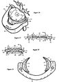
- Figure 1 depicts a common nerve 194 impingement from a protruded disc 100 at or near the narrow channel of the neuroforamen.
- a nerve shield 196 contains a thin and blunt distal tip 213 for reaching into or near the neuroforamen, a trough 202 to partially surround and protect the nerve 194 and an open channel 214 for the nerve 194 to exit from the trough 202.
- the nerve shield 196 is introduced by sliding over the bulging annulus of the disc 100, as shown in Figure 3, to minimize potential damage to the ventral/dorsal ramus nerve root 194. The shield 196 is then gently pressed against the partially surrounded nerve 194.
- another nerve shield 196 is used contralaterany to protect both nerves 194 existing from the neuroforamen, as shown in Figure 4.
- Figure 5 shows an elastic intervertebral disc clamp 198 with an annular contact surface 119, a sloped surface 170, a plateau surface 171 and stops 173 on the compressors 111 portions.
- the saddle-shaped compressors 111 are used to bracket the dysfunctional disc 100 bilaterally.
- the clamp/compressor 198/111 has a support mount 201, an indentation 231 and two widening mounts 199 for engagement with a widening tool, as shown in Figure 6.
- the clamp 198 can be made with nickel-titanium, nitinol, or other elastic alloy or polymers.
- Figure 6 shows a clamp-widening tool 176 equipped with clamp grabbers 177 for engaging with the widening mount 199 on the compressors 111, a pivotal joint 182, handles 181 and a locking mechanism capable of slowly releasing the compressor 111.
- the mechanism contains a hinge 180 anchoring a lock screw 178 fastened with a lock wheel 179.
- the lock screw 178 is sized and configured to fit into a lock slot 183 to lock the handle 181 of the widening tool 176.
- the lock screw 178 can be picked up from the slot 183.
- the lock wheel 179 can be rotated to slowly open the handle 181, thus slowly closing the disc clamp 198.
- Figure 7 depicts widening and placement of the disc clamp 198 by the widening tool 176.
- the clamp 198 fits around the intervertebral disc 100, while nerves 194 are protected by nerve shields 196.
- the distal tips of the compressors 111 are thin and tapered to prevent impingement of the nerve 194.
- the clamp 198 is then slowly released by dialing the lock wheel 179, as shown in Figure 6.
- Figure 8 shows the disc 100 being clamped by the disc clamp 198 as the compressors 111 press the bulging annulus inwardly to alleviate nerve 194 impingement.
- the size of the clamp/compressor 198/111 is enlarged disproportionately to the disc 100, for clarification.
- Figure 9 indicates the locations of compression from the disc clamp 198.
- the preferred compressions are at areas C and I, common protruding locations of the disc 100, with areas E and G as supporting locations. From a disc 100 fastening cadaveric study, nearly the entire disc 100 was distracted, elevated and slightly lengthened from compression by the compressors 111. The portion of annulus remote to the compressors 111 was also distracted, pulling inward. The previously protruded areas B and J in Figure 9 would similarly be distracted as well. Annulus distraction is wide spread and far reaching, way beyond the area of direct compression. The benefit of the far-reaching capability of the compressors 111 is most significant in repairing annular impingements commonly occurring around the narrowed neuroforamen.
- the compressors 111 can be fastened a distance away from the impinging neuroforamen, yet the distraction of the annulus can draw in the distant bulge, alleviating the impingement.
- decompressing the nerve impingement within the neuroforamenal region (the hidden zone) surrounded by the disc 100, vertebral body 159, pedicle and facet joint 129 is very invasive using current surgical procedures, and it may result in increased scarring and a permanently weakened spine.
- annular contact surfaces 119 of the compressors 111 are generally cylindrical or blunt, thickening into the sloped surface 170, as shown in Figure 5, with an optional plateau surface 171.
- an elastic strap 212 is threaded through the support mount 201 and secured by a staple 215 anchored in the vertebral body 159, as shown in Figure 10. More than one strap 212 and staple 215 can be used.
- the strap 212 can be a biodegradable suture or material to initially secure the clamp 198 until the sloped surfaces 170 of the compressors 111 penetrate the annulus and adequately secure the clamp/compressors 198/111.
- Figure 11 depicts a coronal view of initial clamping of the disc 100 with the sloped surface 170 resting on the disc 100.
- the sloped surface 170 of the compressor 111 slowly penetrates into the disc 100 until the stops 173 gently rest on the lateral side of the vertebral body 159 below the disc 100, as shown in Figure 12.
- the stop 173 is a protrusion, a small wall or a leg from the under side of the compressor 111.
- the clamp/compressors 198/111 is designed to compress the protruded annulus, alleviating the nerve impingement.
- the clamp/compressors 198/111 also restricts, support and stabilize the bulging annulus to alleviate pain from segmental instability.
- Figure 13 depicts a coronal view of a scoliotic vertebral segment initially clamped and compressed by the unsymmetrical compressors 111 of a disc clamp 198 (not shown).
- the concave side of the curved vertebral segment is fitted with a thick compressor 111 comprising a wide plateau surface 171, while the convex side of the vertebral segment is fitted with a thin compressor 111 containing a narrow or absent plateau surface 171.
- Figure 14 shows correction or straightening of the scoliotic vertebral segment with time, by selectively wedging, shimming and elevating the concave side of the curved vertebral segment and by inserting the plateau surface 171 of the compressor 111 between the dense epiphyses 115.
- multiple selective disc 100 elevations are required, much as multiple pedicle screws and instrumentation are used in current procedures.
- Scoliosis is corrected through selective shimming by the compressor 111 to alter the lateral curvature of the spine.
- Nickel-titanium compressors 111 are expected to be durable between the epiphyses 115; and the clamp 198 is under minimal strain after settlement in the disc 100.
- the clamp/compressors 198/111 are expected to be long lasting, perhaps even permanent without revisional surgery.
- FIG. 15 depicts a flattened disc 100 with a dehydrated nucleus pulposus 128.
- the initial disc height, H is indicated at the anterior portion of the disc 100.
- a clamp 100 with two symmetrical compressors 111 with wide plateau surfaces 171 is clamped around the flattened disc 100.
- the size of the clamp/compressors 198/111 is enlarged disproportionately to the disc 100, for clarification.
- Gentle compression and wedging action of the clamp/compressors 198/111 allow time for the annulus to grow and thicken.
- the surrounding ligaments including the posterior 195 and anterior 167 longitudinal ligaments and facet joint ligaments, also require time to lengthen.
- FIG. 17 depicts a coronal view of a clamp 198 (not shown) and compressors 111 initially clamped around a disc 100 sandwiched by bone spurs, common among patients with spinal stenosis.
- Figure 18 shows wedging and penetration of the sloped surfaces 170 followed by the plateau surfaces 171 into the disc 100 between the epiphyses 115 of the vertebral bodies 159.
- disc 100 height increases to alleviate nerve impingement common among spinal stenosis patients.
- Penetration of the compressors 111 halts when the stops 173 rest upon the vertebral body 159 below the disc 100.
- the plateau surface 171 maintains disc height without the need of further compression.
- the clamp/compressors 198/111 restore or increase the disc 100 height to minimize or alleviate nerve impingement.
- the clamp 198 and the compressors 111 can be made separately as modular components assembled into a device as shown in Figure 19.
- the vertical cross-section of the clamp 198 can be semi-circular, elliptical, circular or another shape with blunt surfaces to prevent abrasion to the disc 100, abdominal contents or blood vessels.
- the saddle-shaped compressor 111 contains a pivotal peg 172 for inserting into the clamp 198, a smooth and blunt annular contact surface 119, a sloped surface 170, a plateau surface 171 and a stop 173, as shown in Figure 20.
- the concave curvature of the annular contact surface 119 of the compressor 111 is designed to conform and fit partially around the disc 100.
- the compressor 111 can also be made with modular components, as shown in Figure 21.
- the annular contacting part of the compressor 111 can be made with biocompatible polymer, such as polyurethane, polypropylene, polyethylene, PEEK, Delrin, polysulfone, polytetrafluoroethylene, polycarbonate, ultra high molecular weight polyethylene or other low friction polymer.
- the casing 188 with pivotal peg 172, as shown in Figure 21, can be made with stainless steel, titanium, nickel-titanium or metal, or even a polymer.
- the components can be assembled with screws 187 also shown in Figure 21.
- the thickness, curvature, surfaces 119, 170, 171 and/or stops 173 of the compressor 111 can vary to accommodate proper disc 100 compression.
- Figure 22 depicts a vertical cross-sectional view of a compressor 111 containing two stops 173 to improve stability.
- Figure 23 shows a compressor 111 with no stop 173 and a round annular contact surface 119 for gentle compression.
- Figure 24 indicates a compressor 111 with multiple sloped surfaces 170 to gain rapid annular penetration and provide initial stabilization of the clamp 198.
- Figure 25 shows an unsymmetrical slope 170 for shimming into a disc 100 to correct or straighten some kyphosis, scoliosis, lordosis or other spinal deformity.
- Figures 26 shows tissue ingrowth openings 160, indentations or troughs to promote annular ingrowth and stabilization of the compressor 111.
- the plateau surfaces 171 with tissue ingrowth openings 160 can also be non-parallel to each other, as shown in Figure 27, to correct and stabilize some spinal deformities.
- nickel-titanium perhaps is the most suitable material for fabricating the clamp 198.
- the clamp width and reach-in portions are defined in Figure 28.
- the reach-in portions of the clamp 198 are essential for securing the initial fastening and clamping of the disc 100.
- the distal tips 130 are tapered to prevent nerve impingement by the reach-in portions of the clamp 198.
- Figure 29 is a typical strain vs. stress profile of nickel-titanium alloy, a super elastic alloy suitable for fabricating into a disc clamp 198.
- Various compressive stages of a nickel-titanium clamp 198 are also indicated in Figure 29. The compressive force is greatest initially when it presses in the annular protrusion.
- the protrusion As the protrusion is compressed, it relieves the strain of the clamp 198; the compressive force of the clamp 198 rapidly weakens. When the stops 173 reach the vertebral body 159, the compressive force is insignificant, minimizing erosion on bone and annulus. Since the stress on the clamp 198 is minimal after protrusion compression, continual erosion of the disc 100 may not occur even in the absence of the stops 173 on the compressors 111.
- the clamp/compressors 198/111 can also be installed through a lateral incision.
- a widening tool is modified to hold the clamp/compressors 198/111 laterally.
- the modified tool is also used as an extension to install the device 198/111 in the patient.
- Lateral insertion and device 198/111 maneuvering can minimize possible damages from excessive tissue retraction, especially for intervertebral discs 100 surrounded by blood vessels, muscles and nerves.
- the L3-4 disc 100 is sandwiched bilaterally by the Psoas major muscles containing lumbosacral nerve roots, sensitive to excessive retraction.
- Aorta and inferior vena cava are anterior to the disc 100.
- the open side of the widened C-like clamp/compressors 198/111 is oriented vertically either superiorly or inferiorly to the patient, to make the insertion as thin as possible.
- the widened and vertically oriented C-like clamp/compressors 198/111 is inserted between the L3-4 disc 100 and the blood vessels (aorta and inferior vena cava) anterior to the disc 100.
- the clamp/compressors 198/111 is then slowly rotated to orient the open side posteriorly, placing both compressors 111 laterally around the L3- 4 100.
- the clamp/compressors 198/111 is then slowly released to compress the disc 100, followed by retrieval of the widening tool.
- the compressor 111 can also be fastened to a bracket 139 by a screw 187, as shown in Figure 30.
- the bracket 139 is equipped with slits 165 for bolts or screws to fasten into the vertebral body 159, thus compressing the protruded disc 100 with the compressor 111.
- the compressor 111 can also be made with the bracket 139 in one-piece as shown in Figure 31.
- Figure 32 depicts compression of the protruded disc 100 by the compressor/bracket 111/139 fastened by bolts 161 or screws into the vertebral body 159 with the heads of the bolts concealed in the indentation 164 of the bracket 139.
- Figure 33 shows a coronal view of bilateral disc 100 compression fastened with compressor/bracket 111/139 and bolts 161 through the vertebral body 159.
- the brackets 139 serve similar function as the stops 173 with attachment holes 165, 110.
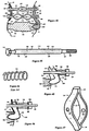
- Figure 34 depicts a bolt 161 with two longitudinal slits 106 cut along the length of the bolt 161.
- the bolt 161 is made with elastic metal, such as nickel-titanium.
- the slits 106 can be cut with laser, water jet, wire or sinker EDM (electron discharging machine).
- Figure 35 depicts the slits 106 after being shimmed open and shaped to form four elastic and compressible struts 107.
- the struts 107 are shaped by inserting shims or fixtures, heating the shimmed bolts 161 to about 500°C for 5-10 minutes, then quickly quenching the heat-treated bolt 161 in cold water before removing the fixtures.
- FIG. 35 shows a bolt 161 with elastic and compressible struts 107 already in open positions, as shown in Figure 35.
- Elastic polymers can also be used to mold into an elastic bolt 161 with compressible struts 107. With the struts 107 open, the length of the bolt 161 is elastically or resiliently shortened.
- Figure 36 shows a sleeve 104 with lumen 225 and four windows 114 sized and configured for the protrusion of the elastic struts 107 of the bolt 161.
- Figure 37 indicates the insertion of the bolt 161 with the elastic struts 107 being resiliently compressed and fitted within the sleeve 104.
- the struts 107 and the windows 114 are in an out-of-phase position, where the windows 114 and direction of struts 107 deployments do not overlap.
- the length of the bolt 161 in out-of-phase position within the sleeve 104 is longer than the length of the bolt 161 with open struts 107, as shown in Figure 35.
- Figure 38 depicts turning of the bolt 161 relative to the sleeve 104 or turning of the sleeve 104 relative to the bolt 161, from the out-of-phase position to an in-phase position, where the windows 114 align with the directions of struts 107 for deployment.
- the elastic struts 107 protrude out of the windows 114 and the overall length of the bolt 161 is elastically or resiliently shortened.
- Figure 39 shows a coronal view of a vertebral motion segment with decreased disc height or symptoms of spinal stenosis.
- Two disc-compressor/brackets 111/139 are laterally anchored with two elastic bolts 161 containing slits 106 within two sleeves 104 in out-of-phase positions.
- the round sleeve head 108 and round nut 162 are designed to allow pivotal movement of the compressor/brackets 111/139 during disc 100 compression.
- the deployment of the struts 107 is activated or initiated by rotating the sleeves 104 from out-of-phase to in-phase positions, allowing the struts 107 to protrude out of the windows 114 of the sleeves 104 and to provide elastic or resilient inward pulling tension on both compressors/brackets 111/139. Similar to the clamp/compressor 198/111, the elastic disc 100 compression allows time for the surrounding ligaments to slowly extend and the annulus of the disc 100 to gradually thicken. As a result, tissue damage is minimized and disc 100 height is elevated to alleviate spinal stenosis, as indicated in Figure 40.
- Figure 40 shows that the plane of the deployed struts 107 is perpendicular to the end plate 105, but ideally the plane of the deployed struts 107 should be parallel to the end plate 105 to maximize the spread of the struts 107 without interfering with the end-plate 105. Therefore, a marking on the bolt head 116 visible to the surgeon can be helpful to identify the plane of struts 107 deployment.
- Figure 41 depicts a mono-lateral disc 100 compression into the concave side of the curved scoliotic vertebral segment.
- Figure 42 shows activation of elastic fastening by setting the bolt 161 and sleeve 104 to the in-phase position, slowly wedging the compressor 111 into the concave side of the curved spine to correct or straighten the scoliotic vertebral segment.
- multiple shimmings can be done in multiple scoliotic segments.
- the degree of individual shimming can be individually selected or fitted with different thicknesses and shapes of the compressor 111.
- the plateau surfaces 171 of the compressor 111 can be non-parallel, as shown in Figure 27, to optimize the fit and correction.
- the plateau surfaces 171 can also be indented with a tissue ingrowth opening 160, also indicated in Figure 27, to promote annular ingrowth and minimize outward slippage of compressor 111.
- Figure 43 indicates a degradable sleeve 218 holding or restricting the elastic struts 107 of the bolt 161 from opening.
- the rate of strut 107 opening is determined by the rate of degradation of the degradable sleeve 218.
- the major benefit to the degradable sleeve 218 is the elimination of the step of turning from the out-of-phase to the in-phase position.
- gradual opening of the struts 107 may be preferred with a slowly eroding degradable polymer to gently and gradually compress and shim into the disc 100.
- the degradable sleeve 218 can be made with polylactide, polyglycolide, poly(lactide-co-glycolide), polycaprolactone, polydioxanone, polyanhydride, trimethylene carbonate, poly-beta-hydroxybutyrate, polyhydroxyvalerate, poly-gama-ethyl-glutamate, poly(DTH iminocarbonate), poly(bisphenol A iminocarbonate), poly-ortho-ester, polycyanoacrylate and polyphosphazene.
- biodegradable materials including collagen, gelatin, cellulose, chitin and dextran. Many of these biodegradable materials are not biocompatible in bone or in disc 100.
- the elastic bolt 161 and the degradable sleeve 218 combination can be used in other industries to provide elastic tensile fastening.
- the degradation can be initiated by water.
- polylactide, polyglycolide or poly(lactide-co-glycolide) is most promising for making the degradable sleeve 218.
- both elastic bolt 161 and sleeve 218 biodegradable for bone joining or tissue fastening.
- Degradation time for DL-polylactide is 12-16 months; 50/50 lactide and glycolide co-polymer is 1-2 months.
- the bolt 161 with open struts 107 can be made by injection molding with DL-polylactide (modulus 1.9 Gpa) and the sleeve 218 with 50/50 lactide and glycolide. Initiated by the degradation of the sleeve 218 within two months, the resilient strength of the bolt 161 begins. After 16 months, hopefully the wound has healed and the bolt 161 and nut 162 will also degrade.
- a coil spring 125 as shown in Figure 44 can also provide compression onto the compressor/bracket 111/139.
- Figure 45 depicts a coronal view of disc 100 compression by a bolt 161, compressor/bracket 111/139, washer 163, compressed coil spring 125, another washer 163 and nut 162.
- Figure 46 shows disc 100 compression and compressor 111 shimming activated by the coil spring 125.
- Figure 47 shows two connecting lift springs 121 curving or arching outwardly. The springs 121 are connected at both ends 118, and a screw hole 120 lies near the center of both springs 121.
- the lift springs 121 can be used as the coil spring 125 in Figures 45 and 46 to elastically compress the intervertebral disc 100.
- Figure 48 indicates a compressor/bracket 111/139 installed anterior to a kyphotic vertebral segment.
- the bracket 139 is anchored by a pivoting means 126 and an elastic fastening means 127 onto the vertebral body 159. With time, the compressor 111 shims into the disc 100 to correct and straighten the kyphotic bend as shown in Figure 49.
- the bracket 139 can also be made with elastic or resilient material installed under strain to compress into the disc 100.
- the compressor/bracket 111/139 can also be lengthened to serve dual functions: disc 100 compression and spinal fusion, as shown in Figure 50. Differing from the currently existing fusion plate, the extended compressor/bracket 111/139 compresses and thickens the disc 100 to increase disc space and possibly alleviate nerve impingement.
- the extended bracket 139 contains a compressor 111 near the mid-portion and screw/bolt holes 110 or slits 165 above and below the compressor 111.
- Figure 51 depicts spinal fusion and disc compression with the extended compressor/bracket 111/139.
- a coronal view of spinal fusion and disc compression with two compressors/brackets 111/139 fastened on the vertebral bodies 159 is shown in Figure 52.
- the bolts 161 or screws are fitted in the slits 165 and evenly fastened to compress the disc 100 and distract the vertebral bodies 159. Then holes are then created in the vertebral bodies to fit bolts 161 or screws through the bracket holes 110 and to further secure the bracket 139.
- Disc 100 compression with spinal fusion is expected to provide disc height elevation, which may be particularly suitable for severe segmental instability or spinal stenosis. Using current technique, disc heights commonly decrease after intervertebral body fusion (Watkins R., et. al., Comparison of Disc Space Heights after Anterior Lumbar Interbody Fusion, Spine 14(8):876-878, 1989).
- Figure 53 depicts a mid-coronal view of a vertebral segment with normal outward bulging of the annular layers during axial compression.
- the annular layers exhibit both inward and outward bulging during similar axial compressions (Seroussi R.E. et. al., Internal Deformations of Intact and Denucleated Human Lumbar Discs Subjected to Compression, Flexion, and Extension Loads, Journal of Orthopaedic Research, 7:122-131, 1989; Meakin J.R., Replacing the nucleus pulposus of the intervertebral disc, Clinical Biomechanics 16:560-565, 2001).
- the inward-outward bulging causes delamination in the inner core of the annular layers, as shown in Figure 54.
- the delaminated annular layer is thin, unsupported and vulnerable to tearing.
- the delamination begins at the layers near the aging nucleus pulposus 128 and leads to seepage of nucleus pulposus 128 and disc 100 protrusion, as shown in Figure 55, (Goel V.K. et. al., Interlaminar Shear Stresses and Laminae Separation in a Disc, Spine, 20(6): 689-98, 1995).
- the compressors 111 provide inward compression to the disc 100, flatten the protrusion and promote inward bulging to minimize the progression of annular delamination and to halt the deterioration of the defective disc 100, as indicated in Figure 56.
- Disc 100 compression by the compressor 111 may also collapse and seal the seeping channels of nucleus pulposus 128 in a herniated disc 100 to minimize chemical irritation to nerves 102.
- Chronic low back pain is generally thought to be caused by nerve 102 impingement.
- MRI often fails to show impingement of neural structures, even in the presence of sciatica.
- saline injection, discography and compression of the longitudinal spinal ligaments can reproduce back pain and sciatica.
- FIG. 57 depicts the ingrowth of sinuvertebral nerves 216 conducting the sensation of tensile or stretching pain from the delaminated pockets within the degenerating disc 100.
- Sinuvertebral nerves 216 normally grow from the surface into the annulus only when the disc 100 begins to degenerate.
- Figure 58 depicts compression of the sinuvertebral nerves 216 leading into the degenerative disc 100 by the compressors 111. With prolonged and intense compression from the compressors 111, the sinuvertebral nerves 216 are expected to cease transmitting signals of pain from the degenerative disc 100 and atrophy within days, thus alleviating pain without discectomy.
- the compressors 111 can also be installed through a protruded disc 100.
- Figure 59 depicts the insertion of a trocar 103 laterally through the protruded disc 100 impinging 184 upon a nerve 102. Insertion of the trocar 103 and compressors 111 can be done endoscopically through a lateral incision as well as through the anterior approach shown in Figure 59.
- Figure 60 indicates the insertion of a dilator 230 over the trocar 103. Then the trocar 103 is withdrawn while the dilator 230 remains in the disc 100, as shown in Figure 61.
- Figure 62 depicts the insertion of a bolt 161, an arcuate compressor 111 and washer 163 assembly into the dilator 230.
- Figure 63 indicates the withdrawal of the dilator 230 to exposure the thread 109 of the bolt 161.
- Figure 64 shows the installation of another compressor 111 onto the bolt 161 with washer 163 and nut 162.
- Figure 65 depicts tightening of the bolt 161, nut 162, compressors 111 and washer 163 assembly to fasten the bulging disc 100 with the sloped surface 170 embedding into the disc 100.
- the resilient bolt 161 with elastic struts 107 can be used with the sleeve 104, as shown in Figure 37, or with the biodegradable sleeve 218 in Figure 43.
- the compressor 111 can also be fastened through the outer layers of the disc 100, and/or with a bracket 139 fastened on the vertebral body 159, as shown in Figure 66.
- the screw entry 217 can be made with a trocar 103, as shown in Figure 67.
- avascularized annulus, bleeding sites 224 at the end-plate 105 are created by the trocar 103 through the bulging disc 100, as shown in Figure 67.
- the entry of the trocar 103 depicted in Figure 67 is slanted or angled upward, able to fit between the superior and inferior surfaces of the laminae, to prevent or minimize laminectomy.
- Figure 68 shows a curved trocar 103 inflicting bleeding sites 224 in both superior and inferior end plates 105, through a posterior/lateral approach.
- a saddle-shaped compressor 111 is shown in Figure 69 with a cylindrical annular contact surface 119, sloped surface 170, round contour tips 130, a screw hole 110 and a trough 223 or indentation to conceal the screw head 226 of a screw 187.
- Figure 70 depicts penetration of the screw 187 through the outer portion of a protruded disc 100 and the end plate 105 into the vertebral body 159.
- Figure 71 shows compression of the protruded disc 100 by the compressor 111 fastened by the screw 187 anchored in the vertebral body 159 to alleviate nerve 102 impingement 184 shown in Figure 70.
- Figure 72 shows a longitudinal view of a fastened disc 100 by the compressor/screw 111/187 with bleeding sites 224 inflicted on both end plates 105.
- the strength of the fastened disc 100 may be greatly enhanced by healing initiated by the surgically inflicted bleeding sites 224.
- Ligament reattachment to bone is a good example.
- a biodegradable suture rated merely for 20 pounds is used to attach a torn ligament onto a surgically inflicted bleeding bone.
- the tensile strength of the reattached ligament can reach 50 pounds; strength increases with time.
- the suture is merely used to maintain the position of the torn ligament; reattachment and healing occur naturally with the surgically inflicted bleeding bone.
- annulus Similar to menisci in knees and articular cartilage in joints, the annulus has a limited capacity for healing and regeneration.
- an arthroscopic awl is used to create multiple holes on the articular cartilage surface, allowing blood and marrow elements to fill the defect, leading to formation of fibrocartilage.
- Patients have reported feeling significant improvement (Blevins F.T., et. al., Treatment of Articular Cartilage Defects in Athletes: An Analysis of Functional Outcome and Lesion Appearance, Orthopedics, Jul 21(7):761-7, 1998). No work has been done on end plate 105 puncturing to promote annular regeneration and adhesion.
- end plates 105 are indeed partly permeable to solutes or nutrients.
- the permeation is associated with the presence of vascular contacts between the marrow spaces of the vertebral body 159 and the hyaline cartilage of the end plate 105.
- One-third of the central portion and only one-tenth of the peripheral zone of the end plates 105 are available for diffusion, exchanging nutrients and waste between the disc 100 and vertebral bodies 159 (S. Holm, et. al., Nutrition of the Intervertebral Disk, Clinical Orthopaedics and Related Research, 129, Nov-Dec:101-14, 1977).
- the disc 100 undergoes rapid repair through the open channels created in the end plate 105, it is possible that fewer pain signals and/or shorter durations of them will be emitted from the degenerated annulus. Nerve 216 ingrowth into the disc 100 may decrease; the risks of future discogenic pain may decrease as well.
- Spondylolisthesis is a condition in which a vertebral body 159 detaches and slips from a disc 100, usually the L5 and S1 disc 100, as shown in Figure 73.
- the slippage usually occurs with some erosion on the facet joint 129, allowing the inferior articular process 143 of L5 to slip over the superior articular process 142 of S1, also shown in Figure 73.
- Spondylolisthesis is normally surgically treated with lumbosacral fusion using instrumentation fastened by screws vulnerable to fatigue and breakage. Instead of using instrumentation to fuse the intervertebral segments, annular adhesion and regeneration may eliminate the need of instruments and hardware.
- bleeding sites 224 are created by the trocar 103 to initiate tissue adhesion between the end-plate 105 and the disc 100, as shown in Figure 74.
- a period (2-4 weeks) of low back immobilization followed by passive motion is required for proper adhesion and adequate reattachment to take place.
- a curved trocar 103 (not part of the claimed invention but described herein to aid further understanding) made with resilient material, such as nickel-titaniun or spring tempered stainless steel, is housed in the lumen of a rigid sleeve 220, as shown in Figure 75.
- the handle of the trocar 103 contains a label 221 indicating the direction of the curvature.
- the curved trocar 103 can be resiliently straightened within the sliding sleeve 220, as shown in Figure 76. The curvature resumes when the sleeve 220 slides away from the curved section of the trocar 103.
- the sleeve/trocar 220/103 assembly is placed perpendicular to the disc 100.
- the trocar 103 By pushing on the handle of the trocar 103, the trocar 103 pierces through the disc 100, resumes the unrestricted curvature and pierces into the end plate 105, as indicated in Figure 77.
- the resiliently curved trocar 103 provides the surgeon greater latitude in terms of patient safety and surgically accessible locations to create bleeding sites 224 at the end plate 105.
- Figure 78 depicts a flattened or bulging disc 100 sandwiched between vertebral bodies 159, a common cause of segmental instability and/or spinal stenosis.
- a pair of compressors/screws 111/187 is fastened through a portion of the disc 100, through the end plate 105 and into the vertebral body 159, as depicted in Figure 79.
- the bulging or unstable sidewall of the disc 100 is compressed, supported, fortified, stiffened, restricted, tightened, pinched in and/or fastened by the compressors/screws 111/187 to minimize segmental instability.
- a pair of compressors/screws 111/187 was used to fasten a cadaveric lumbar motion segment in similar fashion as Figure 79. Motion analysis was done on the fastened cadaveric segment, showing significant increase in stability in flexion/extension and lateral bending motions. The disc height was also increased after disc 100 fastening with the compressors/screws 111/187.
- the result of the cadaveric study indicates potential for treating spinal stenosis by compressing, consolidating and tucking the bulging annulus back between the vertebral bodies 159 to build disc 100 thickness and intervertebral space and to alleviate nerve 102 impingement, as shown in Figure 80.
- screws 187 can be separately anchored into adjacent vertebral bodies 159, as shown in Figure 81.
- the compressor 100 can be fastened with a bolt 161 which penetrates obliquely through the vertebral body 159 and is fastened by a washer 163 and nut 162 assembly, as shown in Figure 82. Promoting tissue ingrowth into the device can also minimize device migration.
- Figure 83 depicts a compressor 111 with tissue ingrowth openings 160, channels or indentations to promote annular ingrowth and prevent migration of the compressor 111.
- the compressor 111 shown in Figure 84 also indicates multiple tissue ingrowth openings 160 penetrating through the thickness of the compressor 111.
- the large ingrowth openings 160 encourage annular ingrowth to prevent device migration with time. Different types of tissue ingrowth can be selected by varying the thickness of the compressor 111.
- the thick compressor 111 with large ingrowth openings 160 fastened adjacent to or over the end plates 105 may encourage bone ingrowth and promote segmental fusion without removing the disc 100.
- Existing spinal fusion procedure with discectomy often contributes to disc space narrowing, which may result in further nerve impingement.
- the segmental fusion induced by the bone ingrowth from upper and lower vertebral bodies 159 into the compressors 111 is accomplished after the distraction of the disc 100 with possible thickening of disc space.
- Osteoconductive material such as bone growth factor collagen and/or hydroxyapatite, can be used to fill the tissue ingrowth openings 160.
- the surfaces of the compressor 111 can also be textured or made porous, similar to hip prostheses, to promote bone ingrowth.
- Figure 84 depicts a compressor 111 with tips 130 slightly curved outwardly to minimizing annular puncture during excessive or unforeseen rotations.
- the compressor 111 can be made with a resilient or elastic material, such as nickel titanium, allowing up to 7% strain without losing shape memory.
- Figure 85 depicts a compressor 111 in an open or predisposed position.
- the resilient compressors 111 can be folded or restricted in a tubular delivery capsule 131, as shown in Figure 86, for endoscopic insertion. In the capsule 131, the resilient compressor 111 is in a delivery position.
- the delivery capsule 131 assembly holding the resilient compressor 111 and a screw 187 is fitted into a delivery device 124, secured by latches 132 and releasable by pinching, as shown in Figure 87.
- the delivery device 124 is equipped with a drive 133 extending into the socket 228 opening of the screw 187.
- the delivery capsule 131 With a small diameter or cross section of the delivery capsule 131, it may be possible to reach the protruded disc 100 in the central zone by inserting the capsule 131 between laminae without laminotomy, as indicated in Figure 87.
- the screw 187 is then advanced through the disc 100 into the end plate 105.
- the advancing screw 187 repels the restricted compressor 111 out of the capsule 131, as shown in Figure 88.
- the cross section of the capsule 131 can be made non-circular.
- the repelled compressor 111 resumes the open position, spreading the legs of resilient compressors 111 on the protruded disc 100, anterior to the nerve 102.
- the screw head 226 presses against the compressor 111, further spreading into a compressed position to fasten the previously bulging annulus, as shown in Figure 89.
- the resilient compressor 111, capsule 131 and screw 187 assembly is uniquely designed to accommodate the large moving range of the compressors 111 from the delivery position to the compressed position, a range even nickel-titanium alloy may not be able to provide.
- the uniqueness is in the open position, about half way between delivery and compressed positions. The magnitudes of the strain from the open to delivery position and from the open to compressed position are nearly equal but in opposite directions. In essence, the open or predisposed position is set at midway, making the large moving range of the compressor 111 possible, without shape memory loss.
- a stabilizer 134 is inserted in the capsule 131 to restrict the screw head 226 within a lumen 117 of the stabilizer 134, as shown in Figure 90.
- the stabilizer 134 contains a lip 135 to prevent the stabilizer 134 from passing through the capsule 131.
- Figure 91 depicts a clamp/compressors 198/111 with large tissue ingrowth openings 160 to ensure annular ingrowth and prevent migration of the clamp/compressor 198/111.
- the widening mounts 199 can also be a portion of the ingrowth openings 160.
- the large ingrowth openings 160 may also allow bone ingrowth to promote spinal fusion 234 between upper and lower vertebral bodies 159, as shown in Figure 92.
- the spinal fusion 234 induced by the compressors 111 can be further promoted by thick and porous compressors 111 bridging between two adjacent vertebral bodies 159, allowing the bone from adjacent vertebral bodies 159 to grow into the ingrowth openings 160 of the compressors 111.
- compressors 111 osteoconductive as hip and joint implants are, allowing bone from adjacent vertebral bodies 159 to embed and fuse with the compressors 111 and create segmental fusion 234.
- the uniqueness of this spinal fusion 234 is that it is accomplished with an intact and repaired disc 100 with the possibility of increased disc height induced by disc 100 compression.
- compressors 111 with osteoconductive property, porous or large ingrowth openings 160 fastened with a bracket 139, bolt 161 or a screw 187 would provide bone ingrowth and spinal fusion 234.
- a wide range of materials can be used to fabricate the compressor 111. Titanium, stainless steel, nickel-titanium alloy or other metallic material is preferred for strength and durability. To minimize tissue erosion, at least a portion of the compressor 111 can be made with biocompatible polymers, such as polyurethane, polypropylene, polyethylene, poly-ether-ether-ketone, acetal resin, polysulfone, polytetrafluoroethylene, polycarbonate, silicon, polyimide, ultra high molecular weight polyethylene or other.
- biocompatible polymers such as polyurethane, polypropylene, polyethylene, poly-ether-ether-ketone, acetal resin, polysulfone, polytetrafluoroethylene, polycarbonate, silicon, polyimide, ultra high molecular weight polyethylene or other.
- the compressor 111 can also be coated with lubricant, growth factor, nerve ingrowth inhibitor, nutrient, buffering agent, collagen, hydroxyapatite, analgesic, sealant for nucleus pulposus, blood clotting, antibiotic, radiopaque or echogenic agents.
- the casing 188 with pivotal peg 172, as shown in Figure 21, can be made with stainless steel, titanium, nickel-titanium or a rigid polymer.
- the compressor 111 After the dysfunctional disc 100 has been repaired by the compressor 111, perhaps accelerated by the surgically inflicted bleeding sites 224, new annulus forms in a non-bulging position. Within months the strength of the repaired disc 100 may be mainly supported by the regenerated annulus cushioned between the vertebral bodies 159, rather than from the fastening strength of the compressor 111. Therefore, it may be possible to fabricate the compressor 111 l and the supporting devices with biodegradable material, such as poly-lactate, poly-glycolic, polycaprolactone, trimethylene carbonate, combinations of these or other materials. A biodegradable device is particularly suitable for young patients to avoid device migration or other related complications in the distant future. All materials should be able to withstand sterilization by gamma, electron beam, steam, ETO, plasma or UV light to prevent infection.
- biodegradable material such as poly-lactate, poly-glycolic, polycaprolactone, trimethylene carbonate, combinations of these or other materials.
- the compressors 111 on a clamp 198, a bracket 139, a bolt 161 (elastic or otherwise) or a screw 187 are used for (1) compressing a protrusion to alleviate impingement, (2) fortifying the annulus to stabilize a motion segment, (3) minimizing the inward/outward bulging to protect the disc 100 from progressive delaminations, (4) atrophying the nerve to treat discogenic pain, (5) correcting the curvature of spinal deformities, (6) elevating the disc space to treat spinal stenosis, (7) sealing the leakage of nucleus pulposus to treat herniated discs 100, and/or (8) promoting bony ingrowth to fuse the motion segment.
Landscapes
- Health & Medical Sciences (AREA)
- Orthopedic Medicine & Surgery (AREA)
- Surgery (AREA)
- Life Sciences & Earth Sciences (AREA)
- Biomedical Technology (AREA)
- Public Health (AREA)
- Neurology (AREA)
- Engineering & Computer Science (AREA)
- Veterinary Medicine (AREA)
- Heart & Thoracic Surgery (AREA)
- Medical Informatics (AREA)
- Molecular Biology (AREA)
- Animal Behavior & Ethology (AREA)
- General Health & Medical Sciences (AREA)
- Nuclear Medicine, Radiotherapy & Molecular Imaging (AREA)
- Dentistry (AREA)
- Oral & Maxillofacial Surgery (AREA)
- Prostheses (AREA)
- Surgical Instruments (AREA)
Claims (26)
- Dispositif de compression pour comprimer un disque intervertébral dysfonctionnel (100), ledit dispositif de compression comprenant :- un élément de compression (111) en forme d'arc ayant une surface de compression,caractérisé par le fait que ladite courbure concave est dimensionnée et configurée pour s'étendre au moins en partie autour du et engager le disque intervertébral, et par le fait que ladite surface de compression a une courbure convexe dans un plan vertical s'étendant à travers celle-ci, et par le fait que le dispositif de compression comprend en outre un moyen de compression (198) pour presser ladite surface de compression contre le disque intervertébral dysfonctionnel (100).- ladite surface de compression ayant une courbure concave (170) dans un plan horizontal s'étendant à travers celle-ci,
- Dispositif de compression selon la revendication 1, dans lequel ladite courbure convexe est dimensionnée et configurée pour s'adapter entre les vertèbres d'un patient.
- Dispositif de compression selon la revendication 1, dans lequel ledit élément de compression a une surface supérieure formant une première surface de plateau et une surface inférieure formant une seconde surface de plateau.
- Dispositif de compression selon la revendication 3, dans lequel au moins l'une desdites première et seconde surfaces de plateau a une entaille ; ou
dans lequel lesdites première et seconde surfaces de plateau sont non parallèles ; ou
dans lequel lesdites première et seconde surfaces de plateau sont généralement parallèles. - Dispositif de compression selon la revendication 1, dans lequel, lorsqu'elle est observée dans ledit plan vertical, ladite surface de compression est généralement arrondie ; ou
dans lequel, lorsqu'elle est observée dans ledit plan vertical, ladite surface de compression s'effile jusqu'à un point arrondi ; ou
dans lequel, lorsqu'elle est observée dans ledit plan vertical, ladite surface de compression est en forme de mamelon ; ou
dans lequel, lorsqu'elle est observée dans ledit plan vertical, ladite surface de compression des courbures multiples. - Dispositif de compression selon la revendication 1, comprenant en outre une première extrémité et une seconde extrémité dudit élément de compression, lesdites première et seconde extrémités formant les extrémités de ladite courbure concave.
- Dispositif de compression selon la revendication 6, dans lequel une profondeur dudit élément de compression est mesurée entre ladite surface de compression et une surface extérieure dudit élément de compression, et dans lequel ladite profondeur se rétrécit jusqu'auxdites première et seconde extrémités ; ou dans lequel lesdites extrémités sont courbées vers l'extérieur.
- Dispositif de compression selon la revendication 1, dans lequel une surface extérieure dudit élément de compression est entaillée pour former une dépression.
- Dispositif de compression selon la revendication 8, dans lequel ladite dépression est dimensionnée et configurée pour contenir une partie dudit moyen de compression et, de préférence, dans lequel ledit moyen de compression est un boulon fileté et une tête dudit boulon est dimensionnée pour s'adapter à l'intérieur de ladite dépression.
- Dispositif de compression selon la revendication 1, comprenant en outre une jambe en saillie s'étendant à partir dudit élément de compression, ladite jambe en saillie étant dimensionnée et configurée pour entrer en contact avec une vertèbre, lorsque ladite surface de compression est au moins partiellement située entre deux vertèbres.
- Dispositif de compression selon la revendication 10, comprenant en outre au moins un trou de fixation s'étendant à travers ladite jambe en saillie ; ou comprenant en outre une seconde jambe en saillie s'étendant à partir dudit élément de compression, dans lequel l'une desdites jambes en saillie s'étend vers le haut et l'autre desdites jambes en saillie s'étend vers le bas.
- Dispositif de compression selon la revendication 1, comprenant en outre une paire d'ouvertures d'engagement d'outils d'introduction s'étendant dans ledit élément de compression sur des côtés opposés de celui-ci.
- Dispositif de compression selon la revendication 1, dans lequel ledit élément de compression est une bride de serrage et ladite bride de serrage s'étend approximativement autour des trois quarts du disque intervertébral.
- Dispositif de compression selon la revendication 13, dans lequel ladite surface de compression est adjacente à un côté du disque et comprenant en outre une seconde surface de compression adjacente à un côté opposé du disque.
- Dispositif de compression selon la revendication 14, dans lequel lesdites première et seconde surfaces de compression ont la même forme ; ou
dans lequel lesdites première et seconde surfaces de compression ont des formes différentes ; ou
dans lequel lesdites première et seconde surfaces de compression sont des pièces modulaires attachables à l'élément de compression. - Dispositif de compression selon la revendication 1, dans lequel ledit élément de compression s'étend approximativement autour d'un quart du disque intervertébral ; ou
dans lequel ledit dispositif de compression est élastique ; ou
dans lequel au moins une partie dudit dispositif de compression est poreuse ; ou
dans lequel ledit dispositif de compression est formé d'un polymère ; ou
dans lequel ledit dispositif de compression est formé d'un alliage nickel-titane. - Dispositif de compression selon la revendication 1, dans lequel ledit dispositif de compression a au moins une ouverture d'interposition de tissu et, de préférence, dans lequel l'os peut se développer à l'intérieur de l'ouverture d'interposition de tissu pour former une fusion des vertèbres.
- Dispositif de compression selon la revendication 1, dans lequel ledit élément de compression est une bride de serrage élastique et l'élasticité de ladite bride de serrage fournit ledit moyen de compression.
- Dispositif de compression selon la revendication 1, dans lequel ledit moyen de compression est un boulon.
- Dispositif de compression selon la revendication 19, dans lequel ledit boulon est formé d'une matière élastique.
- Dispositif de compression selon la revendication 20, dans lequel ledit boulon est sollicité vers une configuration incurvée.
- Dispositif de compression selon la revendication 21, dans lequel ladite configuration incurvée a une pluralité d'arcs ; ou
dans lequel ledit boulon a au moins une fente et dans lequel ladite configuration incurvée est produite par la incurvation vers l'extérieur de ladite fente. - Dispositif de compression selon la revendication 21, comprenant en outre un manchon positionnable autour dudit boulon.
- Dispositif de compression selon la revendication 23, dans lequel ledit manchon a une position en phase et une position en décalage de phase, dans lequel dans ladite position en décalage de phase, ledit boulon est contraint dans une position rectiligne et dans lequel, dans ladite position en phase, ledit boulon est libéré dans ladite configuration incurvée avec au moins une courbe s'étendant à travers une ouverture dans ledit manchon ; ou
dans lequel ledit manchon est formé d'une matière dégradable. - Dispositif de compression selon la revendication 1, dans lequel ledit élément de compression est élastique et, de préférence, comprenant en outre une capsule, ladite capsule étant dimensionnée et configurée pour contenir ledit élément de compression dans une position d'introduction.
- Dispositif de compression selon la revendication 1, dans lequel ledit élément de compression est une bride de serrage élastique et comprenant en outre un outil d'élargissement de l'élément de compression, dimensionné et configuré pour ouvrir et libérer ledit élément de compression et, de préférence, dans lequel le dispositif de compression comprend en outre une première extrémité ayant une première ouverture dans celle-ci et une seconde extrémité ayant une seconde ouverture dans celle-ci, lesdites première et seconde extrémités formant des extrémités de ladite courbure concave, et dans lequel ledit outil d'élargissement de l'élément de compression a deux bras, chaque bras ayant une colonne s'étendant à partir de celui-ci, chacune desdites colonnes étant dimensionnée et configurée pour engager l'une desdites première et seconde ouvertures.
Applications Claiming Priority (11)
| Application Number | Priority Date | Filing Date | Title |
|---|---|---|---|
| US26866601P | 2001-02-13 | 2001-02-13 | |
| US268666P | 2001-02-13 | ||
| US29755601P | 2001-06-11 | 2001-06-11 | |
| US297556P | 2001-06-11 | ||
| US31013101P | 2001-08-03 | 2001-08-03 | |
| US310131P | 2001-08-03 | ||
| US32511101P | 2001-09-26 | 2001-09-26 | |
| US325111P | 2001-09-26 | ||
| US33026001P | 2001-10-17 | 2001-10-17 | |
| PCT/US2002/004301 WO2002064044A2 (fr) | 2001-02-13 | 2002-02-13 | Reparation de disque intervertebral |
| US330260P | 2010-04-30 |
Publications (2)
| Publication Number | Publication Date |
|---|---|
| EP1399077A2 EP1399077A2 (fr) | 2004-03-24 |
| EP1399077B1 true EP1399077B1 (fr) | 2006-08-23 |
Family
ID=27540518
Family Applications (1)
| Application Number | Title | Priority Date | Filing Date |
|---|---|---|---|
| EP02706259A Expired - Lifetime EP1399077B1 (fr) | 2001-02-13 | 2002-02-13 | Dispositif de compression et trocar pour réparation de disque vertébral |
Country Status (6)
| Country | Link |
|---|---|
| US (1) | US20040097927A1 (fr) |
| EP (1) | EP1399077B1 (fr) |
| AT (1) | ATE336953T1 (fr) |
| AU (1) | AU2002240360A1 (fr) |
| DE (1) | DE60214170T2 (fr) |
| WO (1) | WO2002064044A2 (fr) |
Families Citing this family (115)
| Publication number | Priority date | Publication date | Assignee | Title |
|---|---|---|---|---|
| US7998213B2 (en) * | 1999-08-18 | 2011-08-16 | Intrinsic Therapeutics, Inc. | Intervertebral disc herniation repair |
| WO2004100841A1 (fr) | 1999-08-18 | 2004-11-25 | Intrinsic Therapeutics, Inc. | Dispositifs et procedes de densification du noyau du disque vertebral |
| WO2002054978A2 (fr) | 1999-08-18 | 2002-07-18 | Intrinsic Orthopedics Inc | Dispositifs et procede permettant d'augmenter ou de conserver un noyau gelatineux |
| US7717961B2 (en) * | 1999-08-18 | 2010-05-18 | Intrinsic Therapeutics, Inc. | Apparatus delivery in an intervertebral disc |
| US7220281B2 (en) | 1999-08-18 | 2007-05-22 | Intrinsic Therapeutics, Inc. | Implant for reinforcing and annulus fibrosis |
| US8323341B2 (en) | 2007-09-07 | 2012-12-04 | Intrinsic Therapeutics, Inc. | Impaction grafting for vertebral fusion |
| US7972337B2 (en) * | 2005-12-28 | 2011-07-05 | Intrinsic Therapeutics, Inc. | Devices and methods for bone anchoring |
| US6805695B2 (en) | 2000-04-04 | 2004-10-19 | Spinalabs, Llc | Devices and methods for annular repair of intervertebral discs |
| US7223289B2 (en) * | 2002-04-16 | 2007-05-29 | Warsaw Orthopedic, Inc. | Annulus repair systems and techniques |
| US8029511B2 (en) * | 2004-03-22 | 2011-10-04 | Disc Dynamics, Inc. | Multi-stage biomaterial injection system for spinal implants |
| US8425570B2 (en) | 2004-08-09 | 2013-04-23 | Si-Bone Inc. | Apparatus, systems, and methods for achieving anterior lumbar interbody fusion |
| US8388667B2 (en) | 2004-08-09 | 2013-03-05 | Si-Bone, Inc. | Systems and methods for the fixation or fusion of bone using compressive implants |
| US20180228621A1 (en) | 2004-08-09 | 2018-08-16 | Mark A. Reiley | Apparatus, systems, and methods for the fixation or fusion of bone |
| US20070156241A1 (en) | 2004-08-09 | 2007-07-05 | Reiley Mark A | Systems and methods for the fixation or fusion of bone |
| US20060036251A1 (en) | 2004-08-09 | 2006-02-16 | Reiley Mark A | Systems and methods for the fixation or fusion of bone |
| US8414648B2 (en) | 2004-08-09 | 2013-04-09 | Si-Bone Inc. | Apparatus, systems, and methods for achieving trans-iliac lumbar fusion |
| US9949843B2 (en) | 2004-08-09 | 2018-04-24 | Si-Bone Inc. | Apparatus, systems, and methods for the fixation or fusion of bone |
| US9662158B2 (en) | 2004-08-09 | 2017-05-30 | Si-Bone Inc. | Systems and methods for the fixation or fusion of bone at or near a sacroiliac joint |
| WO2006034436A2 (fr) | 2004-09-21 | 2006-03-30 | Stout Medical Group, L.P. | Dispositif de support expansible et procede d'utilisation |
| US7682393B2 (en) | 2004-10-14 | 2010-03-23 | Warsaw Orthopedic, Inc. | Implant system, method, and instrument for augmentation or reconstruction of intervertebral disc |
| US8257356B2 (en) | 2004-10-15 | 2012-09-04 | Baxano, Inc. | Guidewire exchange systems to treat spinal stenosis |
| US8430881B2 (en) | 2004-10-15 | 2013-04-30 | Baxano, Inc. | Mechanical tissue modification devices and methods |
| US8617163B2 (en) | 2004-10-15 | 2013-12-31 | Baxano Surgical, Inc. | Methods, systems and devices for carpal tunnel release |
| US7938830B2 (en) | 2004-10-15 | 2011-05-10 | Baxano, Inc. | Powered tissue modification devices and methods |
| US20100331883A1 (en) | 2004-10-15 | 2010-12-30 | Schmitz Gregory P | Access and tissue modification systems and methods |
| US9247952B2 (en) | 2004-10-15 | 2016-02-02 | Amendia, Inc. | Devices and methods for tissue access |
| US8062300B2 (en) | 2006-05-04 | 2011-11-22 | Baxano, Inc. | Tissue removal with at least partially flexible devices |
| US8221397B2 (en) | 2004-10-15 | 2012-07-17 | Baxano, Inc. | Devices and methods for tissue modification |
| US9101386B2 (en) | 2004-10-15 | 2015-08-11 | Amendia, Inc. | Devices and methods for treating tissue |
| US7887538B2 (en) | 2005-10-15 | 2011-02-15 | Baxano, Inc. | Methods and apparatus for tissue modification |
| US7738969B2 (en) | 2004-10-15 | 2010-06-15 | Baxano, Inc. | Devices and methods for selective surgical removal of tissue |
| US8192435B2 (en) | 2004-10-15 | 2012-06-05 | Baxano, Inc. | Devices and methods for tissue modification |
| US8048080B2 (en) | 2004-10-15 | 2011-11-01 | Baxano, Inc. | Flexible tissue rasp |
| US20110190772A1 (en) | 2004-10-15 | 2011-08-04 | Vahid Saadat | Powered tissue modification devices and methods |
| US7857813B2 (en) | 2006-08-29 | 2010-12-28 | Baxano, Inc. | Tissue access guidewire system and method |
| US7738968B2 (en) | 2004-10-15 | 2010-06-15 | Baxano, Inc. | Devices and methods for selective surgical removal of tissue |
| US7578819B2 (en) | 2005-05-16 | 2009-08-25 | Baxano, Inc. | Spinal access and neural localization |
| US7452369B2 (en) * | 2004-10-18 | 2008-11-18 | Barry Richard J | Spine microsurgery techniques, training aids and implants |
| US20090264939A9 (en) * | 2004-12-16 | 2009-10-22 | Martz Erik O | Instrument set and method for performing spinal nuclectomy |
| US20060241566A1 (en) * | 2005-04-11 | 2006-10-26 | Orthox, Llc | Nucleus Extraction from Spine Intervertebral Disc |
| WO2006116119A2 (fr) * | 2005-04-21 | 2006-11-02 | Spine Wave, Inc. | Systeme de stabilisation dynamique de la colonne vertebrale |
| US20060253199A1 (en) * | 2005-05-03 | 2006-11-09 | Disc Dynamics, Inc. | Lordosis creating nucleus replacement method and apparatus |
| US20060253198A1 (en) * | 2005-05-03 | 2006-11-09 | Disc Dynamics, Inc. | Multi-lumen mold for intervertebral prosthesis and method of using same |
| US20060254599A1 (en) * | 2005-05-10 | 2006-11-16 | Levin Bruce H | Intervention techniques for post-laminectomy syndrome and other spinal disorders |
| WO2007009107A2 (fr) | 2005-07-14 | 2007-01-18 | Stout Medical Group, P.L. | Dispositif de support dilatable et sa methode d'utilisation |
| US20070067034A1 (en) * | 2005-08-31 | 2007-03-22 | Chirico Paul E | Implantable devices and methods for treating micro-architecture deterioration of bone tissue |
| US8998923B2 (en) * | 2005-08-31 | 2015-04-07 | Spinealign Medical, Inc. | Threaded bone filling material plunger |
| US8092456B2 (en) | 2005-10-15 | 2012-01-10 | Baxano, Inc. | Multiple pathways for spinal nerve root decompression from a single access point |
| US8366712B2 (en) | 2005-10-15 | 2013-02-05 | Baxano, Inc. | Multiple pathways for spinal nerve root decompression from a single access point |
| US8062298B2 (en) | 2005-10-15 | 2011-11-22 | Baxano, Inc. | Flexible tissue removal devices and methods |
| US20070213717A1 (en) * | 2006-02-14 | 2007-09-13 | Sdgi Holdings, Inc. | Biological fusion in the vertebral column |
| US8118844B2 (en) * | 2006-04-24 | 2012-02-21 | Warsaw Orthopedic, Inc. | Expandable device for insertion between anatomical structures and a procedure utilizing same |
| EP2023864B1 (fr) | 2006-05-01 | 2019-07-10 | Stout Medical Group, L.P. | Dispositif de soutien expansible |
| US20070265633A1 (en) * | 2006-05-11 | 2007-11-15 | Moon Jon K | Implement and method to extract nucleus from spine intervertebral disc |
| US20080027554A1 (en) * | 2006-07-31 | 2008-01-31 | Talmadge Karen D | Kit and methods of treatment of an intervertebral disc |
| US20090005782A1 (en) * | 2007-03-02 | 2009-01-01 | Chirico Paul E | Fracture Fixation System and Method |
| US20090012564A1 (en) * | 2007-03-07 | 2009-01-08 | Spineworks Medical, Inc. | Transdiscal interbody fusion device and method |
| WO2008109872A2 (fr) * | 2007-03-07 | 2008-09-12 | Spinealign Medical, Inc. | Systèmes, procédés et dispositifs pour la fixation sur l'os d'un tissu mou |
| US20090276048A1 (en) * | 2007-05-08 | 2009-11-05 | Chirico Paul E | Devices and method for bilateral support of a compression-fractured vertebral body |
| WO2008137192A1 (fr) * | 2007-05-08 | 2008-11-13 | Spinealign Medical, Inc. | Systèmes, dispositifs et procédés de stabilisation des os |
| WO2008157513A1 (fr) * | 2007-06-15 | 2008-12-24 | Baxano, Inc. | Dispositifs et procédés pour mesurer l'espace autour d'une racine nerveuse |
| WO2009032695A1 (fr) * | 2007-08-29 | 2009-03-12 | Trinity Orthopedics, Llc | Dispositif et procédés de réparation d'anneau fibreux du disque intervertébral |
| EP2194861A1 (fr) | 2007-09-06 | 2010-06-16 | Baxano, Inc. | Procédé, système et appareil destinés à une localisation neurale |
| US20110196492A1 (en) * | 2007-09-07 | 2011-08-11 | Intrinsic Therapeutics, Inc. | Bone anchoring systems |
| US8551171B2 (en) * | 2007-10-12 | 2013-10-08 | Globus Medical, Inc. | Methods of stabilizing the sacroiliac joint |
| WO2009052194A2 (fr) * | 2007-10-15 | 2009-04-23 | Lanx, Llc | Appareil et procédés d'accès chirurgical |
| US8192436B2 (en) | 2007-12-07 | 2012-06-05 | Baxano, Inc. | Tissue modification devices |
| US20090216260A1 (en) * | 2008-02-20 | 2009-08-27 | Souza Alison M | Interlocking handle |
| US8409206B2 (en) | 2008-07-01 | 2013-04-02 | Baxano, Inc. | Tissue modification devices and methods |
| US9314253B2 (en) | 2008-07-01 | 2016-04-19 | Amendia, Inc. | Tissue modification devices and methods |
| US8398641B2 (en) | 2008-07-01 | 2013-03-19 | Baxano, Inc. | Tissue modification devices and methods |
| MX348805B (es) | 2008-07-14 | 2017-06-28 | Baxano Inc | Dispositivo de modificación de tejidos. |
| WO2010009287A2 (fr) * | 2008-07-16 | 2010-01-21 | Spinealign Medical, Inc. | Pince à broyer |
| US8814937B2 (en) * | 2008-09-18 | 2014-08-26 | Peter L. Mayer | Intervertebral disc prosthesis, method for assembling, method for implanting prosthesis, and method for explanting |
| US8187333B2 (en) * | 2008-09-18 | 2012-05-29 | Mayer Peter L | Intervertebral disc prosthesis and method for implanting and explanting |
| US20100100135A1 (en) * | 2008-10-21 | 2010-04-22 | Phan Christopher U | Bone fixation device having an expandable anchor |
| US20100211176A1 (en) | 2008-11-12 | 2010-08-19 | Stout Medical Group, L.P. | Fixation device and method |
| US9408708B2 (en) | 2008-11-12 | 2016-08-09 | Stout Medical Group, L.P. | Fixation device and method |
| WO2010078488A2 (fr) * | 2008-12-31 | 2010-07-08 | Spinealign Medical, Inc. | Dispositif de stabilisation osseuse auto-déployable |
| MX2011009165A (es) | 2009-03-13 | 2011-09-26 | Baxano Inc | Dispositivo y metodos de localizacion neural flexibles. |
| WO2010127359A1 (fr) * | 2009-05-01 | 2010-11-04 | Vg Innovations, Inc. | Procédé et appareil pour une fusion inter-corps vertébraux |
| US8394102B2 (en) | 2009-06-25 | 2013-03-12 | Baxano, Inc. | Surgical tools for treatment of spinal stenosis |
| US8142477B2 (en) | 2010-01-21 | 2012-03-27 | Warsaw Orthopedic, Inc. | Retaining system |
| US8535380B2 (en) | 2010-05-13 | 2013-09-17 | Stout Medical Group, L.P. | Fixation device and method |
| WO2012027490A2 (fr) | 2010-08-24 | 2012-03-01 | Stout Medical Group, L.P. | Dispositif de soutien et procédé d'utilisation associé |
| EP2618743B1 (fr) | 2010-09-20 | 2018-03-07 | Synthes GmbH | Écarteur pour accès à la colonne vertébrale |
| US9149286B1 (en) | 2010-11-12 | 2015-10-06 | Flexmedex, LLC | Guidance tool and method for use |
| DE102010052113A1 (de) * | 2010-11-20 | 2012-05-24 | Ernst Peter Strecker | Vorrichtungen zur Verbindung knöcherner Strukturen |
| JP2014529445A (ja) | 2011-08-23 | 2014-11-13 | フレックスメデックス,エルエルシー | 組織除去装置及び方法 |
| US10363140B2 (en) | 2012-03-09 | 2019-07-30 | Si-Bone Inc. | Systems, device, and methods for joint fusion |
| EP2822490A4 (fr) | 2012-03-09 | 2016-03-02 | Si Bone Inc | Implant intégré |
| US9393126B2 (en) * | 2012-04-20 | 2016-07-19 | Peter L. Mayer | Bilaterally placed disc prosthesis for spinal implant and method of bilateral placement |
| US9364339B2 (en) * | 2012-04-30 | 2016-06-14 | Peter L. Mayer | Unilaterally placed expansile spinal prosthesis |
| BR112014027319A2 (pt) | 2012-05-04 | 2017-06-27 | Si Bone Inc | implante fenestrado |
| US20130325017A1 (en) * | 2012-05-29 | 2013-12-05 | Zimmer, Inc. | Surgical cutting guide and method |
| WO2014145902A1 (fr) | 2013-03-15 | 2014-09-18 | Si-Bone Inc. | Implants de fixation ou de fusion vertébrale |
| US9498595B2 (en) | 2013-09-17 | 2016-11-22 | Custom Medical Applications, Inc. | Methods for placing a sympathetic block, catheters, catheter assemblies and related methods |
| WO2015057866A1 (fr) | 2013-10-15 | 2015-04-23 | Si-Bone Inc. | Placement d'implant |
| US11147688B2 (en) | 2013-10-15 | 2021-10-19 | Si-Bone Inc. | Implant placement |
| WO2015168478A1 (fr) * | 2014-05-01 | 2015-11-05 | Lorio Morgan Packard | Fixation et systèmes d'articulation sacro-iliaque et procédés les utilisant |
| US9662157B2 (en) | 2014-09-18 | 2017-05-30 | Si-Bone Inc. | Matrix implant |
| WO2016044731A1 (fr) | 2014-09-18 | 2016-03-24 | Si-Bone Inc. | Implants de fixation ou de fusion osseuse |
| US10376206B2 (en) | 2015-04-01 | 2019-08-13 | Si-Bone Inc. | Neuromonitoring systems and methods for bone fixation or fusion procedures |
| AU2017281696B2 (en) | 2016-06-23 | 2022-06-23 | VGI Medical, LLC | Method and apparatus for spinal facet fusion |
| WO2018066921A2 (fr) * | 2016-10-06 | 2018-04-12 | 아주대학교 산학협력단 | Dispositif pour supporter une contrainte d'arceau de cartilage semi-lunaire |
| US10881522B2 (en) * | 2017-02-09 | 2021-01-05 | Nadi S Hibri | Radially expandable annulus reinforcement prosthesis |
| US11812939B2 (en) | 2017-05-15 | 2023-11-14 | Cornell University | Device and system for repairing intervertebral disc herniation and methods of use |
| WO2019067584A1 (fr) | 2017-09-26 | 2019-04-04 | Si-Bone Inc. | Systèmes et procédés de décortication de l'articulation sacro-iliaque |
| WO2020168269A1 (fr) | 2019-02-14 | 2020-08-20 | Si-Bone Inc. | Implants de fixation et/ou de fusion vertébrale |
| US11369419B2 (en) | 2019-02-14 | 2022-06-28 | Si-Bone Inc. | Implants for spinal fixation and or fusion |
| WO2021108590A1 (fr) | 2019-11-27 | 2021-06-03 | Si-Bone, Inc. | Implants de stabilisation osseuse et procédés de placement à travers des joints de si |
| US12083026B2 (en) | 2019-12-09 | 2024-09-10 | Si-Bone Inc. | Sacro-iliac joint stabilizing implants and methods of implantation |
| AU2021397743A1 (en) | 2020-12-09 | 2023-06-22 | Si-Bone Inc. | Sacro-iliac joint stabilizing implants and methods of implantation |
| CA3202177A1 (fr) | 2020-12-17 | 2022-06-23 | Stayble Therapeutics Ab | Composition destinee a etre utilisee dans le traitement d'une hernie discale |
| US20220233202A1 (en) * | 2021-01-22 | 2022-07-28 | Vanderbilt University | Intraoral vertical ramus osteotomy surgical guides |
Family Cites Families (32)
| Publication number | Priority date | Publication date | Assignee | Title |
|---|---|---|---|---|
| US3446212A (en) * | 1965-07-19 | 1969-05-27 | New Research & Dev Lab Inc | Hemostatic clip and applicator therefor |
| US3604425A (en) * | 1969-04-11 | 1971-09-14 | New Research And Dev Lab Inc | Hemostatic clip |
| US3664022A (en) * | 1971-01-28 | 1972-05-23 | Irwin A Small | Drill guide for mandibular staple and staple construction |
| US3741205A (en) * | 1971-06-14 | 1973-06-26 | K Markolf | Bone fixation plate |
| US4217902A (en) * | 1977-05-02 | 1980-08-19 | March Alfred L | Hemostatic clip |
| US4201215A (en) * | 1977-09-06 | 1980-05-06 | Crossett E S | Apparatus and method for closing a severed sternum |
| US4183120A (en) * | 1978-05-19 | 1980-01-15 | Thorne George W | Encircling devices |
| FR2428163A1 (fr) * | 1978-06-06 | 1980-01-04 | Calmettes Marchou Et Cie | Organe de fixation du type collier de serrage |
| US4289123A (en) * | 1980-03-31 | 1981-09-15 | Dunn Harold K | Orthopedic appliance |
| FR2586183A1 (fr) * | 1985-08-19 | 1987-02-20 | Pfc Sarl Ets | Jeu d'aiguilles pour discographie extra-durale et chimio-nucleolyse |
| US4961740B1 (en) * | 1988-10-17 | 1997-01-14 | Surgical Dynamics Inc | V-thread fusion cage and method of fusing a bone joint |
| US5207692A (en) * | 1990-07-30 | 1993-05-04 | Codman & Shurtleff, Inc. | Surgical clip applier with reciprocating clip sleeve and dual ratchet mechanism |
| US5423817A (en) | 1993-07-29 | 1995-06-13 | Lin; Chih-I | Intervertebral fusing device |
| US5395372A (en) * | 1993-09-07 | 1995-03-07 | Danek Medical, Inc. | Spinal strut graft holding staple |
| DE4440346A1 (de) * | 1994-11-13 | 1996-05-15 | Daum Gmbh | Punktionsinstrument |
| FR2733413B1 (fr) * | 1995-04-27 | 1997-10-17 | Jbs Sa | Dispositif de cage cervicale destine a la realisation d'une arthrodese intersomatique |
| US5683394A (en) * | 1995-09-29 | 1997-11-04 | Advanced Spine Fixation Systems, Inc. | Fusion mass constrainer |
| US5997552A (en) * | 1995-10-20 | 1999-12-07 | United States Surgical Corporation | Meniscal fastener applying device |
| US5800550A (en) * | 1996-03-13 | 1998-09-01 | Sertich; Mario M. | Interbody fusion cage |
| US5800433A (en) * | 1996-05-31 | 1998-09-01 | Acromed Corporation | Spinal column retaining apparatus |
| US5681312A (en) * | 1996-05-31 | 1997-10-28 | Acromed Corporation | Spine construct with band clamp |
| US5782832A (en) * | 1996-10-01 | 1998-07-21 | Surgical Dynamics, Inc. | Spinal fusion implant and method of insertion thereof |
| FR2754702B1 (fr) * | 1996-10-18 | 1999-01-08 | Medinov Amp | Dispositif pour solidariser au moins deux corps vertebraux |
| US5951553A (en) * | 1997-07-14 | 1999-09-14 | Sdgi Holdings, Inc. | Methods and apparatus for fusionless treatment of spinal deformities |
| GB9715440D0 (en) * | 1997-07-22 | 1997-09-24 | Dall Desmond Meiring | Bone grip |
| US6045552A (en) * | 1998-03-18 | 2000-04-04 | St. Francis Medical Technologies, Inc. | Spine fixation plate system |
| EP1139883B1 (fr) | 1998-12-31 | 2008-11-19 | Kensey Nash Corporation | Dispositif de fixation de tissus et systeme d'acheminement |
| US6387113B1 (en) * | 1999-02-02 | 2002-05-14 | Biomet, Inc. | Method and apparatus for repairing a torn meniscus |
| US6299613B1 (en) * | 1999-04-23 | 2001-10-09 | Sdgi Holdings, Inc. | Method for the correction of spinal deformities through vertebral body tethering without fusion |
| ATE341280T1 (de) | 2000-06-12 | 2006-10-15 | Jeffrey E Yeung | Reparatur von zwischenwirbelscheiben |
| US6533787B1 (en) * | 2000-07-31 | 2003-03-18 | Sdgi Holdings, Inc. | Contourable spinal staple with centralized and unilateral prongs |
| US6648911B1 (en) * | 2000-11-20 | 2003-11-18 | Avantec Vascular Corporation | Method and device for the treatment of vulnerable tissue site |
-
2002
- 2002-02-13 US US10/470,181 patent/US20040097927A1/en not_active Abandoned
- 2002-02-13 DE DE60214170T patent/DE60214170T2/de not_active Expired - Fee Related
- 2002-02-13 AT AT02706259T patent/ATE336953T1/de not_active IP Right Cessation
- 2002-02-13 WO PCT/US2002/004301 patent/WO2002064044A2/fr active IP Right Grant
- 2002-02-13 AU AU2002240360A patent/AU2002240360A1/en not_active Abandoned
- 2002-02-13 EP EP02706259A patent/EP1399077B1/fr not_active Expired - Lifetime
Also Published As
| Publication number | Publication date |
|---|---|
| WO2002064044A2 (fr) | 2002-08-22 |
| WO2002064044A3 (fr) | 2004-01-08 |
| US20040097927A1 (en) | 2004-05-20 |
| EP1399077A2 (fr) | 2004-03-24 |
| DE60214170T2 (de) | 2007-07-19 |
| ATE336953T1 (de) | 2006-09-15 |
| AU2002240360A1 (en) | 2002-08-28 |
| DE60214170D1 (de) | 2006-10-05 |
Similar Documents
| Publication | Publication Date | Title |
|---|---|---|
| EP1399077B1 (fr) | Dispositif de compression et trocar pour réparation de disque vertébral | |
| EP1299041B1 (fr) | Reparation d'un disque intervertebral | |
| US6579291B1 (en) | Devices and methods for the treatment of spinal disorders | |
| US9451997B2 (en) | Facet device and method | |
| US10327821B2 (en) | Devices and methods for treating vertebral fractures | |
| US9326866B2 (en) | Devices for treating the spine | |
| US8591583B2 (en) | Devices for treating the spine | |
| US20190105082A1 (en) | Systems and methods for posterior dynamic stabilization of the spine | |
| US8900271B2 (en) | Systems and methods for posterior dynamic stabilization of the spine | |
| US6921403B2 (en) | Method and apparatus for spinal distraction and fusion | |
| US8292928B2 (en) | Method and apparatus for spinal distraction and fusion | |
| JP6073666B2 (ja) | 椎骨椎間関節プロテーゼおよびその固定方法 | |
| US20060271197A1 (en) | Spinal disc annulus augmentation | |
| JP2009512538A (ja) | 脊椎動作維持組立体 | |
| US20100198274A1 (en) | Intervertebral disc inserting device |
Legal Events
| Date | Code | Title | Description |
|---|---|---|---|
| PUAI | Public reference made under article 153(3) epc to a published international application that has entered the european phase |
Free format text: ORIGINAL CODE: 0009012 |
|
| 17P | Request for examination filed |
Effective date: 20030819 |
|
| AK | Designated contracting states |
Kind code of ref document: A2 Designated state(s): AT BE CH CY DE DK ES FI FR GB GR IE IT LI LU MC NL PT SE TR |
|
| AX | Request for extension of the european patent |
Extension state: AL LT LV MK RO SI |
|
| GRAP | Despatch of communication of intention to grant a patent |
Free format text: ORIGINAL CODE: EPIDOSNIGR1 |
|
| RTI1 | Title (correction) |
Free format text: INTERVERTEBRAL DISC REPAIR COMPRESSION DEVICE AND TROCAR |
|
| GRAS | Grant fee paid |
Free format text: ORIGINAL CODE: EPIDOSNIGR3 |
|
| GRAA | (expected) grant |
Free format text: ORIGINAL CODE: 0009210 |
|
| AK | Designated contracting states |
Kind code of ref document: B1 Designated state(s): AT BE CH CY DE DK ES FI FR GB GR IE IT LI LU MC NL PT SE TR |
|
| PG25 | Lapsed in a contracting state [announced via postgrant information from national office to epo] |
Ref country code: AT Free format text: LAPSE BECAUSE OF FAILURE TO SUBMIT A TRANSLATION OF THE DESCRIPTION OR TO PAY THE FEE WITHIN THE PRESCRIBED TIME-LIMIT Effective date: 20060823 Ref country code: LI Free format text: LAPSE BECAUSE OF FAILURE TO SUBMIT A TRANSLATION OF THE DESCRIPTION OR TO PAY THE FEE WITHIN THE PRESCRIBED TIME-LIMIT Effective date: 20060823 Ref country code: FI Free format text: LAPSE BECAUSE OF FAILURE TO SUBMIT A TRANSLATION OF THE DESCRIPTION OR TO PAY THE FEE WITHIN THE PRESCRIBED TIME-LIMIT Effective date: 20060823 Ref country code: CH Free format text: LAPSE BECAUSE OF FAILURE TO SUBMIT A TRANSLATION OF THE DESCRIPTION OR TO PAY THE FEE WITHIN THE PRESCRIBED TIME-LIMIT Effective date: 20060823 Ref country code: IT Free format text: LAPSE BECAUSE OF FAILURE TO SUBMIT A TRANSLATION OF THE DESCRIPTION OR TO PAY THE FEE WITHIN THE PRESCRIBED TIME-LIMIT;WARNING: LAPSES OF ITALIAN PATENTS WITH EFFECTIVE DATE BEFORE 2007 MAY HAVE OCCURRED AT ANY TIME BEFORE 2007. THE CORRECT EFFECTIVE DATE MAY BE DIFFERENT FROM THE ONE RECORDED. Effective date: 20060823 Ref country code: NL Free format text: LAPSE BECAUSE OF FAILURE TO SUBMIT A TRANSLATION OF THE DESCRIPTION OR TO PAY THE FEE WITHIN THE PRESCRIBED TIME-LIMIT Effective date: 20060823 Ref country code: BE Free format text: LAPSE BECAUSE OF FAILURE TO SUBMIT A TRANSLATION OF THE DESCRIPTION OR TO PAY THE FEE WITHIN THE PRESCRIBED TIME-LIMIT Effective date: 20060823 |
|
| REG | Reference to a national code |
Ref country code: GB Ref legal event code: FG4D |
|
| REG | Reference to a national code |
Ref country code: CH Ref legal event code: EP |
|
| REG | Reference to a national code |
Ref country code: IE Ref legal event code: FG4D |
|
| REF | Corresponds to: |
Ref document number: 60214170 Country of ref document: DE Date of ref document: 20061005 Kind code of ref document: P |
|
| PG25 | Lapsed in a contracting state [announced via postgrant information from national office to epo] |
Ref country code: SE Free format text: LAPSE BECAUSE OF FAILURE TO SUBMIT A TRANSLATION OF THE DESCRIPTION OR TO PAY THE FEE WITHIN THE PRESCRIBED TIME-LIMIT Effective date: 20061123 Ref country code: DK Free format text: LAPSE BECAUSE OF FAILURE TO SUBMIT A TRANSLATION OF THE DESCRIPTION OR TO PAY THE FEE WITHIN THE PRESCRIBED TIME-LIMIT Effective date: 20061123 |
|
| PG25 | Lapsed in a contracting state [announced via postgrant information from national office to epo] |
Ref country code: ES Free format text: LAPSE BECAUSE OF FAILURE TO SUBMIT A TRANSLATION OF THE DESCRIPTION OR TO PAY THE FEE WITHIN THE PRESCRIBED TIME-LIMIT Effective date: 20061204 |
|
| PG25 | Lapsed in a contracting state [announced via postgrant information from national office to epo] |
Ref country code: PT Free format text: LAPSE BECAUSE OF FAILURE TO SUBMIT A TRANSLATION OF THE DESCRIPTION OR TO PAY THE FEE WITHIN THE PRESCRIBED TIME-LIMIT Effective date: 20070125 |
|
| NLV1 | Nl: lapsed or annulled due to failure to fulfill the requirements of art. 29p and 29m of the patents act | ||
| PG25 | Lapsed in a contracting state [announced via postgrant information from national office to epo] |
Ref country code: MC Free format text: LAPSE BECAUSE OF NON-PAYMENT OF DUE FEES Effective date: 20070228 |
|
| REG | Reference to a national code |
Ref country code: CH Ref legal event code: PL |
|
| EN | Fr: translation not filed | ||
| PLBE | No opposition filed within time limit |
Free format text: ORIGINAL CODE: 0009261 |
|
| STAA | Information on the status of an ep patent application or granted ep patent |
Free format text: STATUS: NO OPPOSITION FILED WITHIN TIME LIMIT |
|
| 26N | No opposition filed |
Effective date: 20070524 |
|
| PG25 | Lapsed in a contracting state [announced via postgrant information from national office to epo] |
Ref country code: IE Free format text: LAPSE BECAUSE OF NON-PAYMENT OF DUE FEES Effective date: 20070213 |
|
| PG25 | Lapsed in a contracting state [announced via postgrant information from national office to epo] |
Ref country code: FR Free format text: LAPSE BECAUSE OF FAILURE TO SUBMIT A TRANSLATION OF THE DESCRIPTION OR TO PAY THE FEE WITHIN THE PRESCRIBED TIME-LIMIT Effective date: 20070511 Ref country code: GR Free format text: LAPSE BECAUSE OF FAILURE TO SUBMIT A TRANSLATION OF THE DESCRIPTION OR TO PAY THE FEE WITHIN THE PRESCRIBED TIME-LIMIT Effective date: 20061124 |
|
| PGFP | Annual fee paid to national office [announced via postgrant information from national office to epo] |
Ref country code: DE Payment date: 20080207 Year of fee payment: 7 Ref country code: GB Payment date: 20080207 Year of fee payment: 7 |
|
| PG25 | Lapsed in a contracting state [announced via postgrant information from national office to epo] |
Ref country code: FR Free format text: LAPSE BECAUSE OF FAILURE TO SUBMIT A TRANSLATION OF THE DESCRIPTION OR TO PAY THE FEE WITHIN THE PRESCRIBED TIME-LIMIT Effective date: 20060823 |
|
| PG25 | Lapsed in a contracting state [announced via postgrant information from national office to epo] |
Ref country code: CY Free format text: LAPSE BECAUSE OF FAILURE TO SUBMIT A TRANSLATION OF THE DESCRIPTION OR TO PAY THE FEE WITHIN THE PRESCRIBED TIME-LIMIT Effective date: 20060823 Ref country code: LU Free format text: LAPSE BECAUSE OF NON-PAYMENT OF DUE FEES Effective date: 20070213 |
|
| PG25 | Lapsed in a contracting state [announced via postgrant information from national office to epo] |
Ref country code: TR Free format text: LAPSE BECAUSE OF FAILURE TO SUBMIT A TRANSLATION OF THE DESCRIPTION OR TO PAY THE FEE WITHIN THE PRESCRIBED TIME-LIMIT Effective date: 20060823 |
|
| GBPC | Gb: european patent ceased through non-payment of renewal fee |
Effective date: 20090213 |
|
| PG25 | Lapsed in a contracting state [announced via postgrant information from national office to epo] |
Ref country code: DE Free format text: LAPSE BECAUSE OF NON-PAYMENT OF DUE FEES Effective date: 20090901 |
|
| PG25 | Lapsed in a contracting state [announced via postgrant information from national office to epo] |
Ref country code: GB Free format text: LAPSE BECAUSE OF NON-PAYMENT OF DUE FEES Effective date: 20090213 |