EP1398858A1 - Band clamp - Google Patents
Band clamp Download PDFInfo
- Publication number
- EP1398858A1 EP1398858A1 EP20030020273 EP03020273A EP1398858A1 EP 1398858 A1 EP1398858 A1 EP 1398858A1 EP 20030020273 EP20030020273 EP 20030020273 EP 03020273 A EP03020273 A EP 03020273A EP 1398858 A1 EP1398858 A1 EP 1398858A1
- Authority
- EP
- European Patent Office
- Prior art keywords
- lock
- band
- insertion member
- band clamp
- wire harness
- Prior art date
- Legal status (The legal status is an assumption and is not a legal conclusion. Google has not performed a legal analysis and makes no representation as to the accuracy of the status listed.)
- Withdrawn
Links
- 238000003780 insertion Methods 0.000 claims abstract description 144
- 230000037431 insertion Effects 0.000 claims abstract description 144
- 210000000078 claw Anatomy 0.000 claims description 46
- 238000006073 displacement reaction Methods 0.000 claims description 14
- 238000009434 installation Methods 0.000 description 16
- 238000010276 construction Methods 0.000 description 6
- 238000000034 method Methods 0.000 description 6
- 239000000463 material Substances 0.000 description 5
- 238000011900 installation process Methods 0.000 description 4
- 239000002699 waste material Substances 0.000 description 4
- 239000000088 plastic resin Substances 0.000 description 3
- 230000002265 prevention Effects 0.000 description 3
- BZHJMEDXRYGGRV-UHFFFAOYSA-N Vinyl chloride Chemical compound ClC=C BZHJMEDXRYGGRV-UHFFFAOYSA-N 0.000 description 1
- 239000003344 environmental pollutant Substances 0.000 description 1
- 238000000926 separation method Methods 0.000 description 1
Images





Classifications
-
- H—ELECTRICITY
- H02—GENERATION; CONVERSION OR DISTRIBUTION OF ELECTRIC POWER
- H02G—INSTALLATION OF ELECTRIC CABLES OR LINES, OR OF COMBINED OPTICAL AND ELECTRIC CABLES OR LINES
- H02G3/00—Installations of electric cables or lines or protective tubing therefor in or on buildings, equivalent structures or vehicles
- H02G3/30—Installations of cables or lines on walls, floors or ceilings
- H02G3/32—Installations of cables or lines on walls, floors or ceilings using mounting clamps
Definitions
- the present invention relates to a band clamp, and more particularly to a band clamp that attaches an automotive wire harness to an aperture in a vehicle body panel through an improved installation procedure.
- clamp 1 is a one-piece synthetic plastic resin fixture incorporating a base plate 1a and an anchor peg 1b that extends upward from the mid-portion of base plate 1a, the purpose of peg 1b being to secure the clamp to the vehicle body.
- Clamp 1 is secured to wire harness W/H by wrapping tape T around wire harness W/H and base plate 1 a.
- Band clamp 2 is a one-piece synthetic plastic resin fixture incorporating band 2a that extends from the lower surface of box-like body 2b, and anchor peg 2c that extends from the upper surface of the box-like body 2b.
- band clamp 2 secures wire harness W/H by band 2a wrapping around the wire harness and passing through slot 2b-1 in body 2b.
- Band tightening tool G is used to tighten band 2a which is maintained in a tightly constricted condition around wire harness W/H by a pawl (not shown), formed on an inner surface slot 2b-1, locking against one of many continuous serrations (not shown) formed on the outer surface of band 2a. The excess portion of band 2a that extends from orifice 2b-1 is sheared off and discarded.
- clamp 1 As shown in Figure 13, the installation of clamp 1 to wire harness W/H requires a tape wrapping operation, and thus undesirably increases the number of components and procedural steps required to install the wire harness. Moreover, the commonly applied vinyl chloride tape becomes an environmental pollutant when eventually discarded.
- band clamp 2 there are various problems regarding the installation of band clamp 2 to wire harness W/H as shown in Figures 14A-14C, one being the need to use an additional component in the form of tool G, and another being the additional procedure in which the excess portion of band 2a must be severed and discarded.
- Other problems exhibited by this type of band clamp are the waste of material that results from cutting off and discarding the excess length of band 2a, the damage that the sharp severed end of band 2a may inflict on adjacent wires, and the possibility of technicians installing the wire harness injuring their hands through inadvertent contact with the sharp severed end of band 2a.
- the present invention provides a band clamp that is able to increase the efficiency of the wire harness installation process, and that allows for easy correction of the differences in spacing between the band clamp positions on the wire harness and the installation aperture positions on the vehicle body.
- the invention resolves the above described shortcomings in the prior art through a band-type wire harness clamp that may be inserted into mounting apertures in a vehicle body panel.
- the band clamp of the present invention is a one-piece fixture including a band portion having ends that can be separated to form a space there between, and a pair of insertion members, one insertion member formed at each end of the band portion adjacent to the space and in opposition to the other insertion member.
- Each insertion member includes an insertion plate that extends from each end of the band portion adjacent to the space, a lock finger that extends outward and downward from the upper edge of the insertion plate, and a lip portion formed at the end of the lock finger.
- An inwardly extending L-shaped lock claw is provided on at least one of the mutually opposed insertion plates, and a lock notch is provided as a cut out portion at the upper edge of the facing insertion plate.
- the wire harness is inserted into the band portion through the space, and the lock claw is hooked over the lock notch to mutually join the insertion members and securely close the band portion around the wire harness.
- the joined insertion members are inserted into the mounting aperture in the vehicle body, thereby placing the lip portion of each lock finger securely against the edges of the mounting aperture to secure the wire harness to the vehicle body panel.
- the present invention eliminates the need for separate installation components, such as the previously noted tape T and band tightening tool G that are required for the installation of conventional clamps, and significantly improves the efficiency of the wire harness installation process by allowing the attachment of the band clamp to the wire harness by simply hooking the lock claw over the lock notch. Moreover, as the band clamp of the present invention eliminates the need to shear off and discard an excess portion of the band clamp, there is no sharp severed band edge to damage adjacent parts of the wire harness nor injure the installation technician, and waste of material is avoided.
- the band clamp of the present invention need not be previously and permanently attached to the wire harness as is required by conventional tape-attached clamps and band tightened clamps, but may be removably attached to the wire harness through the joining and un-joining of the insertion members.
- the attachment method permits the positions of multiple band clamps on the wire harness to be adjusted by simply separating the lock claw from the lock notch, thus allowing the positions of the band clamps on the wire harness to be easily changed in cases where the initial spacing of the band clamps on the wire harness may not align with the spacing of the mounting apertures on the vehicle body panel.
- a stop tab which may be formed as an inwardly extending portion of the lower edge of at least one insertion member, is inserted into a tab notch formed within the opposed insertion member to prevent opposed horizontal displacement of the insertion members.
- Opposed displacement of the insertion members in the vertical plane is prevented by the contact surfaces formed by hooking the lock claw over the lock notch, and opposed displacement of the insertion members in the horizontal plane is prevented by the contact surfaces formed by the insertion of the stop tab into the tab notch.
- An aspect of the present invention provides a band clamp including a band portion having first and second ends; a first insertion member provided on the first end of the band portion and a second insertion member provided on the second end of the band portion; a first lock finger extending outwardly and downwardly from an upper edge of the first insertion member and a second lock finger extending outwardly and downwardly from an upper edge of the second insertion member; and a joining device configured to join together the first and second insertion members; wherein, in a first position of the band clamp, a space is provided between the first insertion member on the first band portion end and the second insertion member on the second band portion end, the space configured to receive a wire harness therethrough, and in a second position, the space is closed and the first insertion member and the second insertion member are joined together by the joining device, the joined together first and second insertion members configured to be inserted into a mounting aperture in a vehicle body panel so that the first and second lock fingers secure the wire harness to the vehicle body panel.
- the first insertion member may include a first insertion plate extending from the first band portion end; the second insertion member may include a second insertion plate extending from the second band portion end; wherein, in the second position, the first and second insertion plates are joined together forming an insertion peg configured to be inserted into the mounting aperture in the vehicle body panel.
- the band clamp may further include a first lip portion provided at an end of the first lock finger and a second lip portion provided at an end of the second lock finger; wherein, the first and second lip portions are configured to contact edges of the mounting aperture in the vehicle body panel when the band clamp is in the second position.
- the band clamp further includes a first semicircular flange provided on the first insertion member and a second semicircular flange provided on the second insertion member, wherein, in the second position, the first and second semicircular flanges are joined together forming a substantially circular flange, the substantially circular flange configured to contact the edges of the mounting aperture on an opposite surface of the vehicle body panel so that the edges of the mounting aperture are positioned between the first and second lip portions and the substantially circular flange.
- the band clamp may be formed unitarily and in one piece.
- the joining device may further include an inwardly extending L-shaped lock claw provided on at least one of the insertion members; and a lock notch provided as a recessed portion at an upper edge of a facing one of the insertion members; wherein, by hooking the lock claw over the lock notch the insertion members are joined together and the band portion is securely closed around the wire harness.
- the band clamp may further include a stop tab provided as an inwardly extending portion of a lower edge of at least one of the insertion members; and a tab notch provided within a facing insertion member; wherein in the second position the stop tab is inserted into the tab notch to form contact surfaces that prevent relative horizontal displacement between the first and second insertion members.
- the joining device may further include first and second L-shaped lock claws provided on the first insertion member, and a third L-shaped lock claw provided on the second insertion member; and first and second lock notches provided on the second insertion member, the third L-shaped lock claw positioned between the first and second lock notches, and a third lock notch provided on the first insertion member, the third lock notch positioned between the first and second L-shaped lock claws; wherein, by hooking the first, second, and third lock claws over the first, second, and third, lock notches, respectively, the first and second insertion members are joined together and the band portion is securely closed around the wire harness.
- the band clamp may further include a first stop tab provided as an inwardly extending portion of a lower edge of the first insertion member and a second stop tab provided as an inwardly extending portion of a lower edge of the second insertion member; and a first tab notch provided on the first insertion member and a second tab notch provided on the second insertion member; wherein in the second position the first stop tab is inserted into the second tab notch and the second stop tab is inserted into the first tab notch to form contact surfaces that prevent relative horizontal displacement between the first and second insertion members.
- a further aspect of the present invention provides in combination, a vehicle body panel portion; a wire harness; and a band clamp.
- Figures 1-5 illustrate a first embodiment of the band clamp of the present invention.
- Figure 1 shows band clamp 10 as a single piece including a C-shaped band 28 whose opposed ends may be separated to define a space 40.
- the band clamp 10 of the present invention may be formed unitarily and in one piece. Further, the band clamp 10 of the present invention may be constructed of any suitable material such as, for example, a synthetic plastic resin.
- a pair of semi-circular flanges 22 and 23 are formed at the opposed ends of band 28 adjacent to space 40, and insertion members 12 and 13 extend from the upper surfaces of semi-circular flanges 22 and 23. The insertion members 12 and 13 may be joined together to form an insertion peg 11.
- Insertion member 13 includes an insertion plate 15 that extends upward from semi-circular flange 23, a lock finger 17 that extends downward from the center of the top edge of insertion plate 15, and a lip portion 17a that projects from the lower edge of lock finger 17.
- Lock claw 21 is an L-shaped member that extends inward from the top edge of insertion plate 15, and lock notch 19 is formed at the top edge of insertion plate 15 opposite lock claw 21.
- insertion member 13 also includes stop tab 27 which projects from the lower edge of insertion plate 15 in opposition to lock claw 21 to prevent horizontal dislocation of the lower portion of insertion member 13.
- tab notch 25 is formed on one side of the lower edge of insertion plate 15 as a space into which opposing stop tab 26 may be inserted.
- Insertion member 12 is a mirror-image construction of insertion member 13 and is located in opposition thereto.
- Lock finger 16 which includes lip portion 16a formed at the lower edge thereof, extends outward and downward from the center of the upper edge of insertion plate 14 above flange 22.
- Lock notch 19 is cut out from one side of the upper edge of insertion plate 15 opposite to L-shaped lock claw 20 that extends inward also from the upper edge of insertion plate 15.
- horizontal displacement prevention stop tab 26 extends from the lower edge of insertion plate 14 on the side of the insertion plate 15 opposite to lock claw 20, and tab notch 24 (see Figure 5) is formed in the lower edge of the side of insertion plate 14 opposite to stop tab 26.
- lock claws 20 and 21 are located opposite to lock notches 18 and 19, respectively, and stop tabs 26 and 27 are located opposite to tab notches 24 and 25, respectively.
- stop tabs 26 and 27 have been inserted into oppositely located tab notches 25 and 24, respectively.
- the respective hooked joining of lock claws 20 and 21 to lock notches 18 and 19 prevents the opposed vertical displacement of insertion plates 14 and 15, and the respective contact of lock claw 20 and 21 against lock fingers 16 and 17 prevents opposed horizontal displacement of insertion members 12 and 13.
- the stop tabs 26 and 27 inserted into tab notches 24 and 25, respectively, also prevents horizontal displacement of insertion members 12 and 13. Tabs 26 and 27 are maintained in position by their respective insertion to tab notches 24 and 25, and can be easily removed there from.
- Insertion peg 11 which is formed by the joining of insertion members 12 and 13, includes a pair of lock fingers 16 and 17 that extend downward and outward from the top edges of insertion plates 14 and 15.
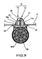
- the distance between lip portions 16a and 17a is larger than the width of mounting aperture H in vehicle body P.
- the edges of the mounting aperture H are sandwiched between lip portions 16a and 17a and flanges 22 and 23, respectively.
- the band clamp of the present invention provides at least the advantage of eliminating the need for separate installation components, such as previously noted tape T and band tightening tool G that are required for the installation of the conventional clamps shown in Figures 13 and 14. Further, the band clamp of the present invention significantly improves the efficiency of the wire harness installation process by allowing the band clamp 10 to be attached to wire harness W/H through the mutual joining of insertion members 12 and 13 by simply hooking lock claws 20 and 21 to lock notches 18 and 19, respectively. Further, as the invention eliminates the need to sever and discard an excess portion of band 28, there is no sharp severed band edge to damage the wire harness nor injure the installation technician, and there is no waste created by the installation process nor waste disposal expense.
- the band clamp 10 of the present invention need not be earlier and permanently attached to wire harness W/H as is required by conventional tape-attached clamps and band tightened clamps, but allows the band 28 to be removably attached to wire harness W/H through the convenient joining and un-joining of insertion members 12 and 13.
- This attachment method allows the position of the band clamp 10 on the wire harness W/H to be adjusted by simply separating lock claws 20 and 21 from lock notches 18 and 19, respectively, thus allowing the positions of multiple band clamps 10 on wire harness W/H to be easily changed in cases where the initial spacing L 1 of band clamps 10 on wire harness W/H may not align with the spacing L2 between mounting apertures H on vehicle body panel P ( Figure 8).
- conventional band clamps 2 must be fixedly attached to wire harness W/H (which can be, for example, a floor harness, engine harness, engine compartment harness or other wire harness component) at points located within specific tolerances needed to align the clamps to mounting points on the vehicle.
- the band clamp 10 of the present invention may be attached to wire harness W/H at unspecified central locations and conveniently aligned with the vehicle mounting points at the time of installation.
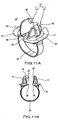
- Figures 11A and 11B illustrate a second embodiment of the band clamp of the present invention in the form of a band clamp 10' which utilizes only one lock claw 20 and one lock notch 19 as well as only one horizontal displacement prevention stop tab 26 and one tab notch 25.
- the positions of stop tab 26 and tab notch 25 may be symmetrically aligned with the positions of lock claw 20 and lock notch 18 in relation to lock fingers 16 and 17.
- Figures 12A and 12B illustrate a third embodiment of the present invention in the form of band clamp 10" which includes two L-shaped lock claws 20 and 29 that extend from opposite ends of the upper edge of insertion plate 14", and two corresponding lock notches 19 and 30 that are formed on each side of the upper edge of insertion plate 15".
- This third embodiment does not include a stop tab and tab notch as does the first embodiment.
- the wire clamp of the present invention provides a significantly improved method of attaching a band-type clamp to a wire harness.
- the invention eliminates the separate components required to install conventional wire harness clamps, components such as tape and special installation tools, through the use of the L-shaped lock claw that hooks over the lock notch.
- the band clamp of the present invention eliminates the need to remove the excess portion of a conventional band clamp, thus eliminating a sharp severed band edge that may damage the wire harness or injure the installation technician, and also eliminates material wastage.
- the wire clamp of the present invention need not be permanently attached to the wire harness before the wire harness is installed onto the vehicle body, but may be initially attached to the wire harness by hooking the lock claw over the lock notch after which the lock claw may be released to change the clamp location as means of accurately aligning the clamp with the mounting apertures on the vehicle body.
- the mechanism whereby the stop tab, which may be provided on at least one insertion member, is joined to the tab notch formed on the other insertion member, provides contact surfaces between the insertion members that prevent opposed horizontal displacement.
- the present disclosure relates to subject matter contained in priority Japanese Application No. JP 2002-264685, filed on September 10, 2002, which is herein expressly incorporated by reference in its entirety.
- a one-piece band clamp that simplifies the installation of a wire harness.
- the band clamp includes a band portion whose separated ends form a space, and a pair of insertion members, each formed at an end of a band portion adjacent to the space.
- the insertion members include insertion plates, lock fingers which include lip portions extending outward and downward from the upper edge of the insertion plates, a lock claw formed on at least one insertion plate, and at least one lock notch formed on the facing insertion plate.
- the wire harness is inserted into a band portion through the space, the lock claws are hooked over the lock notches to join insertion members, which are then inserted into an aperture in a vehicle body panel. Lip portions of the lock fingers press against the edges of the aperture to secure the band clamp to the vehicle body panel.
Landscapes
- Engineering & Computer Science (AREA)
- Architecture (AREA)
- Civil Engineering (AREA)
- Structural Engineering (AREA)
- Installation Of Indoor Wiring (AREA)
- Clamps And Clips (AREA)
- Supports For Pipes And Cables (AREA)
- Connection Of Plates (AREA)
- Insertion Pins And Rivets (AREA)
- Electric Cable Installation (AREA)
Abstract
The clamp (10) has an annular strap section (11) enclosing an interior space and defining an opening (11a) between opposite ends of the strap. Dimension of opening is set to be narrower than a diameter of the wire harness contained in interior space, while annular strap section is bent outwardly to widen opening. The strap section returns to its original position, after containing the wire harness in the space. An insertion engagement sections (12, 13) includes axle plate portions (12a, 13a) projecting from an end of opening and a wing portion bent down from a distal end of the axle plate portion.
Description
- The present invention relates to a band clamp, and more particularly to a band clamp that attaches an automotive wire harness to an aperture in a vehicle body panel through an improved installation procedure.
- Conventionally, wire harnesses have been attached to a vehicle body through a tape-wrapped
clamp 1 as shown in Figure 13, or a manually tightenedband clamp 2 as shown in Figures 14A-14C. As illustrated in Figure 13,clamp 1 is a one-piece synthetic plastic resin fixture incorporating a base plate 1a and ananchor peg 1b that extends upward from the mid-portion of base plate 1a, the purpose ofpeg 1b being to secure the clamp to the vehicle body.Clamp 1 is secured to wire harness W/H by wrapping tape T around wire harness W/H and base plate 1 a. -
Band clamp 2, as shown in Figure 14A, is a one-piece synthetic plastic resinfixture incorporating band 2a that extends from the lower surface of box-like body 2b, andanchor peg 2c that extends from the upper surface of the box-like body 2b. As shown in Figures 14A and 14B,band clamp 2 secures wire harness W/H byband 2a wrapping around the wire harness and passing throughslot 2b-1 inbody 2b. Band tightening tool G is used to tightenband 2a which is maintained in a tightly constricted condition around wire harness W/H by a pawl (not shown), formed on aninner surface slot 2b-1, locking against one of many continuous serrations (not shown) formed on the outer surface ofband 2a. The excess portion ofband 2a that extends fromorifice 2b-1 is sheared off and discarded. - As shown in Figure 13, the installation of
clamp 1 to wire harness W/H requires a tape wrapping operation, and thus undesirably increases the number of components and procedural steps required to install the wire harness. Moreover, the commonly applied vinyl chloride tape becomes an environmental pollutant when eventually discarded. - There are various problems regarding the installation of
band clamp 2 to wire harness W/H as shown in Figures 14A-14C, one being the need to use an additional component in the form of tool G, and another being the additional procedure in which the excess portion ofband 2a must be severed and discarded. Other problems exhibited by this type of band clamp are the waste of material that results from cutting off and discarding the excess length ofband 2a, the damage that the sharp severed end ofband 2a may inflict on adjacent wires, and the possibility of technicians installing the wire harness injuring their hands through inadvertent contact with the sharp severed end ofband 2a. - Moreover, because the positions at which clamp 1 (Figure 13) or band clamp 2 (Figures 14A-14C) connect to wire harness W/H cannot be changed once the clamps are attached to the wire harness, a variation in the spacing of the clamps on the wire harness with respect to the spacing of the clamp installation holes in the vehicle (not shown) can prevent the installation of
anchor pegs - Noting the above-described shortcomings in the prior art construction, the present invention provides a band clamp that is able to increase the efficiency of the wire harness installation process, and that allows for easy correction of the differences in spacing between the band clamp positions on the wire harness and the installation aperture positions on the vehicle body.
- The invention resolves the above described shortcomings in the prior art through a band-type wire harness clamp that may be inserted into mounting apertures in a vehicle body panel. The band clamp of the present invention is a one-piece fixture including a band portion having ends that can be separated to form a space there between, and a pair of insertion members, one insertion member formed at each end of the band portion adjacent to the space and in opposition to the other insertion member. Each insertion member includes an insertion plate that extends from each end of the band portion adjacent to the space, a lock finger that extends outward and downward from the upper edge of the insertion plate, and a lip portion formed at the end of the lock finger.
- An inwardly extending L-shaped lock claw is provided on at least one of the mutually opposed insertion plates, and a lock notch is provided as a cut out portion at the upper edge of the facing insertion plate. The wire harness is inserted into the band portion through the space, and the lock claw is hooked over the lock notch to mutually join the insertion members and securely close the band portion around the wire harness. The joined insertion members are inserted into the mounting aperture in the vehicle body, thereby placing the lip portion of each lock finger securely against the edges of the mounting aperture to secure the wire harness to the vehicle body panel.
- The present invention eliminates the need for separate installation components, such as the previously noted tape T and band tightening tool G that are required for the installation of conventional clamps, and significantly improves the efficiency of the wire harness installation process by allowing the attachment of the band clamp to the wire harness by simply hooking the lock claw over the lock notch. Moreover, as the band clamp of the present invention eliminates the need to shear off and discard an excess portion of the band clamp, there is no sharp severed band edge to damage adjacent parts of the wire harness nor injure the installation technician, and waste of material is avoided.
- In addition, the band clamp of the present invention need not be previously and permanently attached to the wire harness as is required by conventional tape-attached clamps and band tightened clamps, but may be removably attached to the wire harness through the joining and un-joining of the insertion members. The attachment method permits the positions of multiple band clamps on the wire harness to be adjusted by simply separating the lock claw from the lock notch, thus allowing the positions of the band clamps on the wire harness to be easily changed in cases where the initial spacing of the band clamps on the wire harness may not align with the spacing of the mounting apertures on the vehicle body panel.
- Further, a stop tab, which may be formed as an inwardly extending portion of the lower edge of at least one insertion member, is inserted into a tab notch formed within the opposed insertion member to prevent opposed horizontal displacement of the insertion members.
- Opposed displacement of the insertion members in the vertical plane is prevented by the contact surfaces formed by hooking the lock claw over the lock notch, and opposed displacement of the insertion members in the horizontal plane is prevented by the contact surfaces formed by the insertion of the stop tab into the tab notch.
- An aspect of the present invention provides a band clamp including a band portion having first and second ends; a first insertion member provided on the first end of the band portion and a second insertion member provided on the second end of the band portion; a first lock finger extending outwardly and downwardly from an upper edge of the first insertion member and a second lock finger extending outwardly and downwardly from an upper edge of the second insertion member; and a joining device configured to join together the first and second insertion members; wherein, in a first position of the band clamp, a space is provided between the first insertion member on the first band portion end and the second insertion member on the second band portion end, the space configured to receive a wire harness therethrough, and in a second position, the space is closed and the first insertion member and the second insertion member are joined together by the joining device, the joined together first and second insertion members configured to be inserted into a mounting aperture in a vehicle body panel so that the first and second lock fingers secure the wire harness to the vehicle body panel. Further, the first insertion member may include a first insertion plate extending from the first band portion end; the second insertion member may include a second insertion plate extending from the second band portion end; wherein, in the second position, the first and second insertion plates are joined together forming an insertion peg configured to be inserted into the mounting aperture in the vehicle body panel. Further, the band clamp may further include a first lip portion provided at an end of the first lock finger and a second lip portion provided at an end of the second lock finger; wherein, the first and second lip portions are configured to contact edges of the mounting aperture in the vehicle body panel when the band clamp is in the second position.
- In a further aspect of the present invention, the band clamp further includes a first semicircular flange provided on the first insertion member and a second semicircular flange provided on the second insertion member, wherein, in the second position, the first and second semicircular flanges are joined together forming a substantially circular flange, the substantially circular flange configured to contact the edges of the mounting aperture on an opposite surface of the vehicle body panel so that the edges of the mounting aperture are positioned between the first and second lip portions and the substantially circular flange. Additionally, the band clamp may be formed unitarily and in one piece. The joining device may further include an inwardly extending L-shaped lock claw provided on at least one of the insertion members; and a lock notch provided as a recessed portion at an upper edge of a facing one of the insertion members; wherein, by hooking the lock claw over the lock notch the insertion members are joined together and the band portion is securely closed around the wire harness. The band clamp may further include a stop tab provided as an inwardly extending portion of a lower edge of at least one of the insertion members; and a tab notch provided within a facing insertion member; wherein in the second position the stop tab is inserted into the tab notch to form contact surfaces that prevent relative horizontal displacement between the first and second insertion members. Further, the joining device may further include first and second L-shaped lock claws provided on the first insertion member, and a third L-shaped lock claw provided on the second insertion member; and first and second lock notches provided on the second insertion member, the third L-shaped lock claw positioned between the first and second lock notches, and a third lock notch provided on the first insertion member, the third lock notch positioned between the first and second L-shaped lock claws; wherein, by hooking the first, second, and third lock claws over the first, second, and third, lock notches, respectively, the first and second insertion members are joined together and the band portion is securely closed around the wire harness. Further, the band clamp may further include a first stop tab provided as an inwardly extending portion of a lower edge of the first insertion member and a second stop tab provided as an inwardly extending portion of a lower edge of the second insertion member; and a first tab notch provided on the first insertion member and a second tab notch provided on the second insertion member; wherein in the second position the first stop tab is inserted into the second tab notch and the second stop tab is inserted into the first tab notch to form contact surfaces that prevent relative horizontal displacement between the first and second insertion members.
- A further aspect of the present invention provides in combination, a vehicle body panel portion; a wire harness; and a band clamp.
- The above, and other objects, features and advantages of the present invention will be made apparent from the following description of the preferred embodiments, given as nonlimiting examples, with reference to the accompanying drawings in which:
- Figure 1 is a perspective view of the band clamp according to a first embodiment of the present invention;
- Figure 2 is a side view of the band clamp in the embodiment of Figure 1;
- Figure 3 is a cross sectional view of the band clamp in the embodiment of Figure 1;
- Figure 4 is a top view of the band clamp in the embodiment of Figure 1;
- Figure 5 is a bottom view of the band clamp in the embodiment of Figure 1;
- Figure 6 is a perspective view of the band clamp in the embodiment of Figure 1 attached to a wire harness;
- Figure 7A is a cross sectional view of the band clamp of the present invention attached to a wire harness shown in Figure 6;
- Figure 7B is a side view of the band clamp of the present invention attached to a wire harness shown in Figure 6;
- Figure 8 illustrates the spacing between wire harness mounting apertures on a vehicle body;
- Figure 9 illustrates the band clamp shown in Figure 8 inserted into the mounting apertures on a vehicle body;
- Figure 10 is a perspective view of a wire harness with a plurality of types of band clamps attached thereto;
- Figure 11A is a perspective view of the band clamp according to a second embodiment of the present invention;
- Figure 11B is a side view of the band clamp of the present invention according to the embodiment of Figure 11A;
- Figure 12A is a perspective view of the band clamp according to a third embodiment of the present invention;
- Figure 12B is a side view of the band clamp of the present invention according to the embodiment of Figure 12A;
- Figure 13 is a perspective view of a conventional wire harness clamp;
- Figure 14A is a side view of a conventional band clamp;
- Figure 14B is a cross sectional view of the band clamp of Figure 14A attached to a wire harness;
- Figure 14C is a perspective view of the band clamp of Figure 14A attached to a wire harness.
-
- The particulars shown herein are by way of example and for purposes of illustrative discussion of the embodiments of the present invention only and are presented in the cause of providing what is believed to be the most useful and readily understood description of the principles and conceptual aspects of the present invention. In this regard, no attempt is made to show structural details of the present invention in more detail than is necessary for the fundamental understanding of the present invention, the description is taken with the drawings making apparent to those skilled in the art how the forms of the present invention may be embodied in practice.
- Figures 1-5 illustrate a first embodiment of the band clamp of the present invention. Figure 1 shows
band clamp 10 as a single piece including a C-shapedband 28 whose opposed ends may be separated to define aspace 40. Theband clamp 10 of the present invention may be formed unitarily and in one piece. Further, theband clamp 10 of the present invention may be constructed of any suitable material such as, for example, a synthetic plastic resin. A pair ofsemi-circular flanges band 28 adjacent tospace 40, andinsertion members semi-circular flanges insertion members insertion peg 11. -
Insertion member 13 includes aninsertion plate 15 that extends upward fromsemi-circular flange 23, alock finger 17 that extends downward from the center of the top edge ofinsertion plate 15, and alip portion 17a that projects from the lower edge oflock finger 17.Lock claw 21 is an L-shaped member that extends inward from the top edge ofinsertion plate 15, and locknotch 19 is formed at the top edge ofinsertion plate 15opposite lock claw 21. As shown in Figures 2, 4, and 5,insertion member 13 also includesstop tab 27 which projects from the lower edge ofinsertion plate 15 in opposition to lockclaw 21 to prevent horizontal dislocation of the lower portion ofinsertion member 13. As shown in Figures 2 and 5,tab notch 25 is formed on one side of the lower edge ofinsertion plate 15 as a space into which opposingstop tab 26 may be inserted. -
Insertion member 12 is a mirror-image construction ofinsertion member 13 and is located in opposition thereto.Lock finger 16, which includeslip portion 16a formed at the lower edge thereof, extends outward and downward from the center of the upper edge ofinsertion plate 14 aboveflange 22.Lock notch 19 is cut out from one side of the upper edge ofinsertion plate 15 opposite to L-shapedlock claw 20 that extends inward also from the upper edge ofinsertion plate 15. As shown in Figures 2, 4, and 5, horizontal displacementprevention stop tab 26 extends from the lower edge ofinsertion plate 14 on the side of theinsertion plate 15 opposite to lockclaw 20, and tab notch 24 (see Figure 5) is formed in the lower edge of the side ofinsertion plate 14 opposite to stoptab 26. - According to the construction of the present invention, the
lock claws notches tabs tab notches - The following will describe the procedure of installing
band clamp 10 onto a wire harness W/H. Wire harness W/H is inserted into C-shapedband 28 ofband clamp 10 through thespace 40, which has been created by the mutual separation ofinsertion members insertion members claw 20 oninsertion member 12 hooks overlock notch 19 oninsertion member 13, and lockclaw 21 oninsertion member 13 hooks overlock notch 18 oninsertion member 12.Insertion peg 11 is thus formed from the joining ofinsertion members semi-circular flanges - With
insertion members tabs tab notches lock claws notches insertion plates lock claw lock fingers insertion members stop tabs tab notches insertion members Tabs tab notches -
Insertion peg 11, which is formed by the joining ofinsertion members lock fingers insertion plates lip portions lip portions flanges - The band clamp of the present invention provides at least the advantage of eliminating the need for separate installation components, such as previously noted tape T and band tightening tool G that are required for the installation of the conventional clamps shown in Figures 13 and 14. Further, the band clamp of the present invention significantly improves the efficiency of the wire harness installation process by allowing the
band clamp 10 to be attached to wire harness W/H through the mutual joining ofinsertion members lock claws notches band 28, there is no sharp severed band edge to damage the wire harness nor injure the installation technician, and there is no waste created by the installation process nor waste disposal expense. - In addition, the
band clamp 10 of the present invention need not be earlier and permanently attached to wire harness W/H as is required by conventional tape-attached clamps and band tightened clamps, but allows theband 28 to be removably attached to wire harness W/H through the convenient joining and un-joining ofinsertion members band clamp 10 on the wire harness W/H to be adjusted by simply separatinglock claws lock notches initial spacing L 1 of band clamps 10 on wire harness W/H may not align with the spacing L2 between mounting apertures H on vehicle body panel P (Figure 8). - Further, as shown in Figure 10, conventional band clamps 2 must be fixedly attached to wire harness W/H (which can be, for example, a floor harness, engine harness, engine compartment harness or other wire harness component) at points located within specific tolerances needed to align the clamps to mounting points on the vehicle. The
band clamp 10 of the present invention, however, may be attached to wire harness W/H at unspecified central locations and conveniently aligned with the vehicle mounting points at the time of installation. - Figures 11A and 11B illustrate a second embodiment of the band clamp of the present invention in the form of a band clamp 10' which utilizes only one
lock claw 20 and onelock notch 19 as well as only one horizontal displacementprevention stop tab 26 and onetab notch 25. The positions ofstop tab 26 andtab notch 25 may be symmetrically aligned with the positions oflock claw 20 andlock notch 18 in relation to lockfingers - As there is only one
lock claw 20 in this second embodiment, less pressure is required to hooklock claw 20 overlock notch 19 in order to join insertion members 12' and 13'. Moreover, as lateral displacementprevention stop tab 26 andtab notch 25 are in symmetrical alignment withlock claw 20 andlock notch 19, the structure by which lockclaw 20 contacts lockfinger 17 prevents insertion member 12' from sliding horizontally against insertion member 13' in one direction, and the structure by which stoptab 26 is inserted intotab notch 25 prevents insertion member 12' from sliding horizontally against insertion member 13' in the opposite direction. Descriptions of the second embodiment parts identical to those in the first embodiment have been omitted. - Figures 12A and 12B illustrate a third embodiment of the present invention in the form of
band clamp 10" which includes two L-shapedlock claws insertion plate 14", and twocorresponding lock notches insertion plate 15". This third embodiment does not include a stop tab and tab notch as does the first embodiment. - With
lock claws lock notches lock claw 20 maintains contact with one side oflock finger 17 preventsinsertion member 12" from sliding in one direction with respect toinsertion member 13", and the construction by which lockclaw 29 maintains contact with the opposite side oflock finger 17 preventsinsertion member 12" from sliding in the opposite direction. Descriptions of the third embodiment parts identical to those of the first embodiment have been omitted. - As previously described, the wire clamp of the present invention provides a significantly improved method of attaching a band-type clamp to a wire harness. The invention eliminates the separate components required to install conventional wire harness clamps, components such as tape and special installation tools, through the use of the L-shaped lock claw that hooks over the lock notch. Moreover, the band clamp of the present invention eliminates the need to remove the excess portion of a conventional band clamp, thus eliminating a sharp severed band edge that may damage the wire harness or injure the installation technician, and also eliminates material wastage.
- Further, the wire clamp of the present invention need not be permanently attached to the wire harness before the wire harness is installed onto the vehicle body, but may be initially attached to the wire harness by hooking the lock claw over the lock notch after which the lock claw may be released to change the clamp location as means of accurately aligning the clamp with the mounting apertures on the vehicle body.
- Moreover, the mechanism whereby the stop tab, which may be provided on at least one insertion member, is joined to the tab notch formed on the other insertion member, provides contact surfaces between the insertion members that prevent opposed horizontal displacement.
- Although the invention has been described with reference to an exemplary embodiment, it is understood that the words that have been used are words of description and illustration, rather than words of limitation. Changes may be made within the purview of the appended claims, as presently stated and as amended, without departing from the scope and spirit of the invention in its aspects. Although the invention has been described with reference to particular means, materials and embodiments, the invention is not intended to be limited to the particulars disclosed. Rather, the invention extends to all functionally equivalent structures, methods, and uses such as are within the scope of the appended claims.
- The present disclosure relates to subject matter contained in priority Japanese Application No. JP 2002-264685, filed on September 10, 2002, which is herein expressly incorporated by reference in its entirety.
A one-piece band clamp that simplifies the installation of a wire harness. The band clamp includes a band portion whose separated ends form a space, and a pair of insertion members, each formed at an end of a band portion adjacent to the space. The insertion members include insertion plates, lock fingers which include lip portions extending outward and downward from the upper edge of the insertion plates, a lock claw formed on at least one insertion plate, and at least one lock notch formed on the facing insertion plate. The wire harness is inserted into a band portion through the space, the lock claws are hooked over the lock notches to join insertion members, which are then inserted into an aperture in a vehicle body panel. Lip portions of the lock fingers press against the edges of the aperture to secure the band clamp to the vehicle body panel.
Claims (10)
- A band clamp comprising:wherein, in a first position of said band clamp, a space is provided between said first insertion member on said first band portion end and said second insertion member on said second band portion end, said space configured to receive a wire harness therethrough, and in a second position, said space is closed and said first insertion member and said second insertion member are joined together by said joining device, said joined together first and second insertion members configured to be inserted into a mounting aperture in a vehicle body panel so that said first and second lock fingers secure the wire harness to the vehicle body panel.a band portion having first and second ends;a first insertion member provided on said first end of said band portion and a second insertion member provided on said second end of said band portion;a first lock finger extending outwardly and downwardly from an upper edge of said first insertion member and a second lock finger extending outwardly and downwardly from an upper edge of said second insertion member; anda joining device configured to join together said first and second insertion members;
- The band clamp according to claim 1, wherein:wherein, in said second position, said first and second insertion plates arejoined together forming an insertion peg configured to be inserted into the mounting aperture in the vehicle body panel.said first insertion member comprises a first insertion plate extending from said first band portion end;said second insertion member comprises a second insertion plate extending from said second band portion end; and
- The band clamp according to claim 1 or 2, further comprising:wherein, said first and second lip portions are configured to contact edges of the mounting aperture in the vehicle body panel when said band clamp is in said second position.a first lip portion provided at an end of said first lock finger and a second lip portion provided at an end of said second lock finger;
- The band clamp according to claim 3, further comprising:wherein, in said second position, said first and second semicircular flanges are joined together forming a substantially circular flange, said substantially circular flange configured to contact the edges of the mounting aperture on an opposite surface of the vehicle body panel so that the edges of the mounting aperture are positioned between said first and second lip portions and said substantially circular flange.a first semicircular flange provided on said first insertion member and a second semicircular flange provided on said second insertion member;
- The band clamp according to any of claims 1 to 4, wherein said band clamp is formed unitarily and in one piece.
- The band clamp according to any of claims 1 to 5, said joining device further comprising:wherein, by hooking said lock claw over said lock notch said insertion members are joined together and said band portion is securely closed around the wire hamess.an inwardly extending L-shaped lock claw provided on at least one of said insertion members; anda lock notch provided as a recessed portion at an upper edge of a facing one of said insertion members;
- The band clamp according to any of claims 1 to 6, said band clamp further comprising:wherein in said second position said stop tab is inserted into said tab notch to form contact surfaces that prevent relative horizontal displacement between said first and second insertion members.a stop tab provided as an inwardly extending portion of a lower edge of at least one of said insertion members; anda tab notch provided within a facing one of said insertion members;
- The band clamp according to any of claims 1 to 7, said joining device further comprising:wherein, by hooking said first, second, and third lock claws over said first, second, and third, lock notches, respectively, said first and second insertion members are joined together and said band portion is securely closed around the wire harness.first and second L-shaped lock claws provided on said first insertion member, and a third L-shaped lock claw provided on said second insertion member; andfirst and second lock notches provided on said second insertion member, said third L-shaped lock claw positioned between said first and second lock notches, and a third lock notch provided on said first insertion member, said third lock notch positioned between said first and second L-shaped lock claws;
- The band clamp according to any of claims 1 to 8, said band clamp further comprising:wherein in said second position said first stop tab is inserted into said second tab notch and said second stop tab is inserted into said first tab notch to form contact surfaces that prevent relative horizontal displacement between said first and second insertion members.a first stop tab provided as an inwardly extending portion of a lower edge of said first insertion member and a second stop tab provided as an inwardly extending portion of a lower edge of said second insertion member;and a first tab notch provided on said first insertion member and a second tab notch provided on said second insertion member;
- In combination, a vehicle body panel portion;
a wire harness; and
a band clamp according tto any of claims 1 to 9.
Applications Claiming Priority (2)
| Application Number | Priority Date | Filing Date | Title |
|---|---|---|---|
| JP2002264685A JP2004104924A (en) | 2002-09-10 | 2002-09-10 | Clamp |
| JP2002264685 | 2002-09-10 |
Publications (1)
| Publication Number | Publication Date |
|---|---|
| EP1398858A1 true EP1398858A1 (en) | 2004-03-17 |
Family
ID=31884762
Family Applications (1)
| Application Number | Title | Priority Date | Filing Date |
|---|---|---|---|
| EP20030020273 Withdrawn EP1398858A1 (en) | 2002-09-10 | 2003-09-08 | Band clamp |
Country Status (4)
| Country | Link |
|---|---|
| US (1) | US20040046088A1 (en) |
| EP (1) | EP1398858A1 (en) |
| JP (1) | JP2004104924A (en) |
| CN (1) | CN1485563A (en) |
Families Citing this family (13)
| Publication number | Priority date | Publication date | Assignee | Title |
|---|---|---|---|---|
| US7442875B2 (en) * | 2005-03-14 | 2008-10-28 | Federal-Mogul World Wide, Inc. | Protective sheath with integral biased flap closure |
| US20090113677A1 (en) * | 2007-11-02 | 2009-05-07 | Marketing Displays Inc. | Sliding Member Bollard Bracket |
| JP5140414B2 (en) | 2007-12-28 | 2013-02-06 | 住友電装株式会社 | Corrugated clamp |
| KR200448238Y1 (en) | 2008-01-11 | 2010-03-25 | 경신공업 주식회사 | Band cable for fixing wire harness |
| JPWO2011030693A1 (en) * | 2009-09-09 | 2013-02-07 | 株式会社ニックス | Mounting band |
| JP2012095434A (en) * | 2010-10-26 | 2012-05-17 | Sumitomo Wiring Syst Ltd | Band clip |
| US8157222B1 (en) | 2010-10-29 | 2012-04-17 | Toyota Motor Engineering & Manufacturing North America, Inc. | Wire harness clamp |
| DE102010043565A1 (en) * | 2010-11-08 | 2012-05-10 | Robert Bosch Gmbh | Fastening device for a conduit and method for attaching a conduit |
| WO2014193351A1 (en) * | 2013-05-29 | 2014-12-04 | International Engine Intellectual Property Company, Llc | Harness clip and system for clipping wiring harness |
| JP6296969B2 (en) | 2014-12-10 | 2018-03-20 | 株式会社ニフコ | clip |
| DE102019205361B4 (en) * | 2019-04-12 | 2024-07-25 | Lisi Automotive Kkp Gmbh & Co. Kg | Mounting clamp, parking brake and motor vehicle |
| KR102661765B1 (en) * | 2021-08-20 | 2024-04-30 | 엔브이에이치코리아(주) | Wire mounting clip |
| CN114006301B (en) * | 2021-10-14 | 2024-10-15 | 合肥中科蓝睿科技有限公司 | Self-compensating type electrified ignition integrated installation device |
Citations (5)
| Publication number | Priority date | Publication date | Assignee | Title |
|---|---|---|---|---|
| FR2529722A1 (en) * | 1982-06-30 | 1984-01-06 | Itw De France | Snap-fastenable retention clip for cables, wires, cable bundles (harnesses) or the like. |
| JPH1019168A (en) * | 1996-06-28 | 1998-01-23 | Piolax Inc | Retaining clip |
| JPH10220429A (en) * | 1997-01-31 | 1998-08-21 | Suzuki Motor Corp | Wiring harness mounting structure |
| JPH11252753A (en) * | 1998-02-27 | 1999-09-17 | Sumitomo Wiring Syst Ltd | Automotive wire harness clamp |
| JP2001330175A (en) * | 2000-05-22 | 2001-11-30 | Yazaki Corp | Wire harness fixing clip |
-
2002
- 2002-09-10 JP JP2002264685A patent/JP2004104924A/en not_active Withdrawn
-
2003
- 2003-08-25 CN CNA03154942XA patent/CN1485563A/en active Pending
- 2003-09-08 EP EP20030020273 patent/EP1398858A1/en not_active Withdrawn
- 2003-09-08 US US10/656,135 patent/US20040046088A1/en not_active Abandoned
Patent Citations (5)
| Publication number | Priority date | Publication date | Assignee | Title |
|---|---|---|---|---|
| FR2529722A1 (en) * | 1982-06-30 | 1984-01-06 | Itw De France | Snap-fastenable retention clip for cables, wires, cable bundles (harnesses) or the like. |
| JPH1019168A (en) * | 1996-06-28 | 1998-01-23 | Piolax Inc | Retaining clip |
| JPH10220429A (en) * | 1997-01-31 | 1998-08-21 | Suzuki Motor Corp | Wiring harness mounting structure |
| JPH11252753A (en) * | 1998-02-27 | 1999-09-17 | Sumitomo Wiring Syst Ltd | Automotive wire harness clamp |
| JP2001330175A (en) * | 2000-05-22 | 2001-11-30 | Yazaki Corp | Wire harness fixing clip |
Also Published As
| Publication number | Publication date |
|---|---|
| US20040046088A1 (en) | 2004-03-11 |
| CN1485563A (en) | 2004-03-31 |
| JP2004104924A (en) | 2004-04-02 |
Similar Documents
| Publication | Publication Date | Title |
|---|---|---|
| US20040046088A1 (en) | Band clamp | |
| US4811922A (en) | Flat wire harness attaching unit | |
| US6398170B1 (en) | Wire harness fixing clip | |
| US5135188A (en) | Attachable bundling strap | |
| US7956285B2 (en) | Floor stand for mounting an electrical box | |
| EP2468581B1 (en) | Fastener | |
| EP3333997A1 (en) | Protective bundle routing grommet for wide range panel thicknesses | |
| US7654492B2 (en) | Wire bundle support system | |
| EP3628905A2 (en) | Adjustable p-clamp with multiple mounting options | |
| JPH06104025A (en) | connector | |
| EP0293451B1 (en) | A fastening means for fastening a protective sheet material to a scaffold or a similar frame structure | |
| EP4455493A1 (en) | Fixings with cutting guides | |
| US20240360922A1 (en) | Cable Tie Cradle Mount Fixings | |
| US11101628B2 (en) | Wire harness retaining system | |
| JP4875177B2 (en) | Band clamp | |
| JP3458662B2 (en) | Clamp for holding joint connector | |
| JP3423361B2 (en) | Unity band | |
| WO2009084302A1 (en) | Wire harness fastener | |
| JP2003267160A (en) | Body mounting structure of wire harness | |
| JP2575496Y2 (en) | Holders such as wire harness | |
| US20160339852A1 (en) | Method and apparatus for securing a vehicle wiring harness | |
| JP2003160070A (en) | WIRE HARNESS REMOVING COMPONENT AND WIRE HARNESS WITH THE SAME | |
| JPS6325432Y2 (en) | ||
| WO2015083521A1 (en) | Temporary fixing structure for vehicle component | |
| JPH0710672U (en) | Clip for wire harness |
Legal Events
| Date | Code | Title | Description |
|---|---|---|---|
| PUAI | Public reference made under article 153(3) epc to a published international application that has entered the european phase |
Free format text: ORIGINAL CODE: 0009012 |
|
| AK | Designated contracting states |
Kind code of ref document: A1 Designated state(s): AT BE BG CH CY CZ DE DK EE ES FI FR GB GR HU IE IT LI LU MC NL PT RO SE SI SK TR |
|
| AX | Request for extension of the european patent |
Extension state: AL LT LV MK |
|
| AKX | Designation fees paid | ||
| REG | Reference to a national code |
Ref country code: DE Ref legal event code: 8566 |
|
| STAA | Information on the status of an ep patent application or granted ep patent |
Free format text: STATUS: THE APPLICATION IS DEEMED TO BE WITHDRAWN |
|
| 18D | Application deemed to be withdrawn |
Effective date: 20040920 |