EP3628905A2 - Adjustable p-clamp with multiple mounting options - Google Patents
Adjustable p-clamp with multiple mounting options Download PDFInfo
- Publication number
- EP3628905A2 EP3628905A2 EP19199457.3A EP19199457A EP3628905A2 EP 3628905 A2 EP3628905 A2 EP 3628905A2 EP 19199457 A EP19199457 A EP 19199457A EP 3628905 A2 EP3628905 A2 EP 3628905A2
- Authority
- EP
- European Patent Office
- Prior art keywords
- clamp
- mounting
- bracket assembly
- mounting bracket
- clamp member
- Prior art date
- Legal status (The legal status is an assumption and is not a legal conclusion. Google has not performed a legal analysis and makes no representation as to the accuracy of the status listed.)
- Withdrawn
Links
- 230000007246 mechanism Effects 0.000 claims abstract description 34
- 239000000463 material Substances 0.000 claims description 5
- 239000004033 plastic Substances 0.000 claims description 5
- 229920003023 plastic Polymers 0.000 claims description 5
- 239000000853 adhesive Substances 0.000 claims description 3
- 230000001070 adhesive effect Effects 0.000 claims description 3
- 230000002787 reinforcement Effects 0.000 claims description 3
- 239000013536 elastomeric material Substances 0.000 claims 1
- 239000007769 metal material Substances 0.000 claims 1
- 238000000034 method Methods 0.000 abstract description 9
- 239000002184 metal Substances 0.000 description 17
- 230000000712 assembly Effects 0.000 description 9
- 238000000429 assembly Methods 0.000 description 9
- 230000008901 benefit Effects 0.000 description 5
- 238000009434 installation Methods 0.000 description 4
- 230000014759 maintenance of location Effects 0.000 description 3
- 238000012986 modification Methods 0.000 description 3
- 230000004048 modification Effects 0.000 description 3
- 238000010276 construction Methods 0.000 description 2
- 238000005336 cracking Methods 0.000 description 2
- 206010016256 fatigue Diseases 0.000 description 2
- 210000003811 finger Anatomy 0.000 description 2
- 238000002955 isolation Methods 0.000 description 2
- 230000008569 process Effects 0.000 description 2
- 230000008439 repair process Effects 0.000 description 2
- 210000003813 thumb Anatomy 0.000 description 2
- 230000002411 adverse Effects 0.000 description 1
- 238000013459 approach Methods 0.000 description 1
- 230000009286 beneficial effect Effects 0.000 description 1
- 230000000295 complement effect Effects 0.000 description 1
- 108010038764 cytoplasmic linker protein 170 Proteins 0.000 description 1
- 230000001627 detrimental effect Effects 0.000 description 1
- 239000000835 fiber Substances 0.000 description 1
- 229920002457 flexible plastic Polymers 0.000 description 1
- 239000012530 fluid Substances 0.000 description 1
- 239000002783 friction material Substances 0.000 description 1
- 230000003993 interaction Effects 0.000 description 1
- 239000002991 molded plastic Substances 0.000 description 1
- 229920000642 polymer Polymers 0.000 description 1
- 239000002861 polymer material Substances 0.000 description 1
- 230000002265 prevention Effects 0.000 description 1
- 239000012858 resilient material Substances 0.000 description 1
- 238000000926 separation method Methods 0.000 description 1
Images


Classifications
-
- F—MECHANICAL ENGINEERING; LIGHTING; HEATING; WEAPONS; BLASTING
- F16—ENGINEERING ELEMENTS AND UNITS; GENERAL MEASURES FOR PRODUCING AND MAINTAINING EFFECTIVE FUNCTIONING OF MACHINES OR INSTALLATIONS; THERMAL INSULATION IN GENERAL
- F16L—PIPES; JOINTS OR FITTINGS FOR PIPES; SUPPORTS FOR PIPES, CABLES OR PROTECTIVE TUBING; MEANS FOR THERMAL INSULATION IN GENERAL
- F16L3/00—Supports for pipes, cables or protective tubing, e.g. hangers, holders, clamps, cleats, clips, brackets
- F16L3/08—Supports for pipes, cables or protective tubing, e.g. hangers, holders, clamps, cleats, clips, brackets substantially surrounding the pipe, cable or protective tubing
- F16L3/12—Supports for pipes, cables or protective tubing, e.g. hangers, holders, clamps, cleats, clips, brackets substantially surrounding the pipe, cable or protective tubing comprising a member substantially surrounding the pipe, cable or protective tubing
- F16L3/123—Supports for pipes, cables or protective tubing, e.g. hangers, holders, clamps, cleats, clips, brackets substantially surrounding the pipe, cable or protective tubing comprising a member substantially surrounding the pipe, cable or protective tubing and extending along the attachment surface
-
- F—MECHANICAL ENGINEERING; LIGHTING; HEATING; WEAPONS; BLASTING
- F16—ENGINEERING ELEMENTS AND UNITS; GENERAL MEASURES FOR PRODUCING AND MAINTAINING EFFECTIVE FUNCTIONING OF MACHINES OR INSTALLATIONS; THERMAL INSULATION IN GENERAL
- F16B—DEVICES FOR FASTENING OR SECURING CONSTRUCTIONAL ELEMENTS OR MACHINE PARTS TOGETHER, e.g. NAILS, BOLTS, CIRCLIPS, CLAMPS, CLIPS OR WEDGES; JOINTS OR JOINTING
- F16B2/00—Friction-grip releasable fastenings
- F16B2/02—Clamps, i.e. with gripping action effected by positive means other than the inherent resistance to deformation of the material of the fastening
- F16B2/06—Clamps, i.e. with gripping action effected by positive means other than the inherent resistance to deformation of the material of the fastening external, i.e. with contracting action
-
- F—MECHANICAL ENGINEERING; LIGHTING; HEATING; WEAPONS; BLASTING
- F16—ENGINEERING ELEMENTS AND UNITS; GENERAL MEASURES FOR PRODUCING AND MAINTAINING EFFECTIVE FUNCTIONING OF MACHINES OR INSTALLATIONS; THERMAL INSULATION IN GENERAL
- F16L—PIPES; JOINTS OR FITTINGS FOR PIPES; SUPPORTS FOR PIPES, CABLES OR PROTECTIVE TUBING; MEANS FOR THERMAL INSULATION IN GENERAL
- F16L3/00—Supports for pipes, cables or protective tubing, e.g. hangers, holders, clamps, cleats, clips, brackets
- F16L3/08—Supports for pipes, cables or protective tubing, e.g. hangers, holders, clamps, cleats, clips, brackets substantially surrounding the pipe, cable or protective tubing
-
- F—MECHANICAL ENGINEERING; LIGHTING; HEATING; WEAPONS; BLASTING
- F16—ENGINEERING ELEMENTS AND UNITS; GENERAL MEASURES FOR PRODUCING AND MAINTAINING EFFECTIVE FUNCTIONING OF MACHINES OR INSTALLATIONS; THERMAL INSULATION IN GENERAL
- F16B—DEVICES FOR FASTENING OR SECURING CONSTRUCTIONAL ELEMENTS OR MACHINE PARTS TOGETHER, e.g. NAILS, BOLTS, CIRCLIPS, CLAMPS, CLIPS OR WEDGES; JOINTS OR JOINTING
- F16B11/00—Connecting constructional elements or machine parts by sticking or pressing them together, e.g. cold pressure welding
- F16B11/006—Connecting constructional elements or machine parts by sticking or pressing them together, e.g. cold pressure welding by gluing
-
- F—MECHANICAL ENGINEERING; LIGHTING; HEATING; WEAPONS; BLASTING
- F16—ENGINEERING ELEMENTS AND UNITS; GENERAL MEASURES FOR PRODUCING AND MAINTAINING EFFECTIVE FUNCTIONING OF MACHINES OR INSTALLATIONS; THERMAL INSULATION IN GENERAL
- F16B—DEVICES FOR FASTENING OR SECURING CONSTRUCTIONAL ELEMENTS OR MACHINE PARTS TOGETHER, e.g. NAILS, BOLTS, CIRCLIPS, CLAMPS, CLIPS OR WEDGES; JOINTS OR JOINTING
- F16B2/00—Friction-grip releasable fastenings
- F16B2/02—Clamps, i.e. with gripping action effected by positive means other than the inherent resistance to deformation of the material of the fastening
- F16B2/06—Clamps, i.e. with gripping action effected by positive means other than the inherent resistance to deformation of the material of the fastening external, i.e. with contracting action
- F16B2/08—Clamps, i.e. with gripping action effected by positive means other than the inherent resistance to deformation of the material of the fastening external, i.e. with contracting action using bands
-
- F—MECHANICAL ENGINEERING; LIGHTING; HEATING; WEAPONS; BLASTING
- F16—ENGINEERING ELEMENTS AND UNITS; GENERAL MEASURES FOR PRODUCING AND MAINTAINING EFFECTIVE FUNCTIONING OF MACHINES OR INSTALLATIONS; THERMAL INSULATION IN GENERAL
- F16L—PIPES; JOINTS OR FITTINGS FOR PIPES; SUPPORTS FOR PIPES, CABLES OR PROTECTIVE TUBING; MEANS FOR THERMAL INSULATION IN GENERAL
- F16L3/00—Supports for pipes, cables or protective tubing, e.g. hangers, holders, clamps, cleats, clips, brackets
- F16L3/08—Supports for pipes, cables or protective tubing, e.g. hangers, holders, clamps, cleats, clips, brackets substantially surrounding the pipe, cable or protective tubing
- F16L3/10—Supports for pipes, cables or protective tubing, e.g. hangers, holders, clamps, cleats, clips, brackets substantially surrounding the pipe, cable or protective tubing divided, i.e. with two or more members engaging the pipe, cable or protective tubing
- F16L3/1075—Supports for pipes, cables or protective tubing, e.g. hangers, holders, clamps, cleats, clips, brackets substantially surrounding the pipe, cable or protective tubing divided, i.e. with two or more members engaging the pipe, cable or protective tubing with two members, the two members being joined with a hinge on one side and fastened together on the other side
-
- F—MECHANICAL ENGINEERING; LIGHTING; HEATING; WEAPONS; BLASTING
- F16—ENGINEERING ELEMENTS AND UNITS; GENERAL MEASURES FOR PRODUCING AND MAINTAINING EFFECTIVE FUNCTIONING OF MACHINES OR INSTALLATIONS; THERMAL INSULATION IN GENERAL
- F16L—PIPES; JOINTS OR FITTINGS FOR PIPES; SUPPORTS FOR PIPES, CABLES OR PROTECTIVE TUBING; MEANS FOR THERMAL INSULATION IN GENERAL
- F16L3/00—Supports for pipes, cables or protective tubing, e.g. hangers, holders, clamps, cleats, clips, brackets
- F16L3/08—Supports for pipes, cables or protective tubing, e.g. hangers, holders, clamps, cleats, clips, brackets substantially surrounding the pipe, cable or protective tubing
- F16L3/12—Supports for pipes, cables or protective tubing, e.g. hangers, holders, clamps, cleats, clips, brackets substantially surrounding the pipe, cable or protective tubing comprising a member substantially surrounding the pipe, cable or protective tubing
- F16L3/137—Supports for pipes, cables or protective tubing, e.g. hangers, holders, clamps, cleats, clips, brackets substantially surrounding the pipe, cable or protective tubing comprising a member substantially surrounding the pipe, cable or protective tubing and consisting of a flexible band
-
- F—MECHANICAL ENGINEERING; LIGHTING; HEATING; WEAPONS; BLASTING
- F16—ENGINEERING ELEMENTS AND UNITS; GENERAL MEASURES FOR PRODUCING AND MAINTAINING EFFECTIVE FUNCTIONING OF MACHINES OR INSTALLATIONS; THERMAL INSULATION IN GENERAL
- F16L—PIPES; JOINTS OR FITTINGS FOR PIPES; SUPPORTS FOR PIPES, CABLES OR PROTECTIVE TUBING; MEANS FOR THERMAL INSULATION IN GENERAL
- F16L3/00—Supports for pipes, cables or protective tubing, e.g. hangers, holders, clamps, cleats, clips, brackets
- F16L3/14—Hangers in the form of bands or chains
-
- F—MECHANICAL ENGINEERING; LIGHTING; HEATING; WEAPONS; BLASTING
- F16—ENGINEERING ELEMENTS AND UNITS; GENERAL MEASURES FOR PRODUCING AND MAINTAINING EFFECTIVE FUNCTIONING OF MACHINES OR INSTALLATIONS; THERMAL INSULATION IN GENERAL
- F16L—PIPES; JOINTS OR FITTINGS FOR PIPES; SUPPORTS FOR PIPES, CABLES OR PROTECTIVE TUBING; MEANS FOR THERMAL INSULATION IN GENERAL
- F16L3/00—Supports for pipes, cables or protective tubing, e.g. hangers, holders, clamps, cleats, clips, brackets
- F16L3/22—Supports for pipes, cables or protective tubing, e.g. hangers, holders, clamps, cleats, clips, brackets specially adapted for supporting a number of parallel pipes at intervals
- F16L3/237—Supports for pipes, cables or protective tubing, e.g. hangers, holders, clamps, cleats, clips, brackets specially adapted for supporting a number of parallel pipes at intervals for two pipes
-
- H—ELECTRICITY
- H02—GENERATION; CONVERSION OR DISTRIBUTION OF ELECTRIC POWER
- H02G—INSTALLATION OF ELECTRIC CABLES OR LINES, OR OF COMBINED OPTICAL AND ELECTRIC CABLES OR LINES
- H02G3/00—Installations of electric cables or lines or protective tubing therefor in or on buildings, equivalent structures or vehicles
- H02G3/02—Details
- H02G3/04—Protective tubing or conduits, e.g. cable ladders or cable troughs
-
- H—ELECTRICITY
- H02—GENERATION; CONVERSION OR DISTRIBUTION OF ELECTRIC POWER
- H02G—INSTALLATION OF ELECTRIC CABLES OR LINES, OR OF COMBINED OPTICAL AND ELECTRIC CABLES OR LINES
- H02G3/00—Installations of electric cables or lines or protective tubing therefor in or on buildings, equivalent structures or vehicles
- H02G3/30—Installations of cables or lines on walls, floors or ceilings
- H02G3/32—Installations of cables or lines on walls, floors or ceilings using mounting clamps
Definitions
- the present invention relates generally to retaining mechanisms. Particularly, the present invention is directed to an offset mounted clamp whereby an elongate bundle is secured and offset a distance from the mounting hole.
- a non-limiting example of a device 10 that is configured to adjustably attach an elongate item to a support structure is shown.
- the device 10 very closely resembles a "P-clamp" and is hereinafter referred to as an adjustable P-clamp 10.
- the adjustable P-clamp 10 functions to secure elongate items, such as wires, cables and the like into bundles 12, shown in phantom lines, and to further secure the bundles 12 to an adjacent support structure 14, see Fig. 27 for an example.
- the bundle 12 may comprise a single object or several objects, such as wires, conduits, or cables that are flexible or rigid, hot or cold, or fluid transporting hoses or tubes, fiber optics, conduits, plant vines, etc. Some elongate items may also be contained within the bore of a conventional tubular conduit.
- the adjustable P-clamp 10 is particularly well suited for use in applications requiring releasable clamping while the adjustable P-clamp 10 is attached to a support structure 14.
- the adjustable P-clamp 10 includes two principal components, namely an integrally formed clamp member 16 and a mounting element 18.
- the clamp members 16A, 16B define a pair of substantially symmetrical, arcuately shaped profiles 20A, 20B, hereinafter referred to as the arcuate profiles, 20A, 20B.
- the arcuate profiles 20A, 20B are shaped and dimensioned to encircle an elongate element, such as a bundle 12 and are joined by a hinge mechanism 22.
- the arcuate profiles 20A, 20B may further define ridges 21 projecting from the arcuate profiles 20A, 20B.
- the clamp members 16A, 16B may include a cradle member 58, as will be discussed with reference to Figs. 10 through 12 .
- the hinge mechanism 22 may include an area of reduced thickness 24 which allows the hinge mechanism 22 to flex or bend freely during the installation and securing of a bundle 12. This type of hinge mechanism may be referred to as a living hinge. Alternative embodiments may be envisioned using other types of hinge mechanisms, such as a piano hinge, a butt hinge, etc.
- the hinge mechanism provides the benefit of maintaining alignment of the arcuate tongue 34 with the slot opening 36 throughout the process of closing the first clamp member 16A around the bundle 12.
- the hinge mechanism 22 may also include a hinge interlocking mechanism 26.
- the interlocking mechanism 26 comprises an arcuate projection 28 that is configured to be received into a corresponding channel 30.
- the interaction of the interlocking arcuate projection 28 in the channel 30 provides a secondary retention across the hinge which would be required in the unlikely event the area of reduced thickness in the hinge mechanism 22 would fail, due to cracking or other failure, thereby retaining the clamp members 16A, 16B in a closed position should the area of reduced thickness 24 fail, due to cracking or other loss of function.
- the hinge interlocking mechanism 26 may not be required, but provides backup retention and may be desired by consumers concerned about the robustness of plastic components.
- the clamp member 16 may be seen to further include a lock mechanism 32.
- the lock mechanism 32 is comprised of an arcuate tongue 34 and a slot opening 36 having an engaging pawl 38, particularly see Figs. 5 and 7 .
- a protruding beam 40 of the adjustable P-clamp 10 is positioned perpendicular to the arcuate tongue 34 and provides a platform or depression for an operators fingers or thumb press upon the first clamp member 16A when engaging the arcuate tongue 34 into the slot opening 36.
- the first clamp member 16A may include an extending arcuate tongue 34, with a slot opening 36 being positioned adjacent a second clamp member 16B.
- the arcuate tongue 34 is preferably molded with a plurality of serrations 42, which extend along the length of the arcuate tongue 34 and across the width of the arcuate tongue 34.
- the serrations 42 may be arranged in two parallel rows as shown.
- the arcuate tongue 34 is adapted to be received in a corresponding slot opening 36 adjacent the second arcuate profile 20B.
- the engaging pawl 38 located in the slot opening 36 may include teeth 44 thereon.
- the teeth 44 may be arranged in two parallel rows to correspond to the width of the serrations 42 on the arcuate tongue 34.
- the serrations 42 engage the teeth 44 on the engaging pawl 38 when the arcuate tongue 34 is inserted into the slot opening 36 for retaining the bundle 12.
- the arcuate tongue 34 may further include a pair of spaced apart serration rails 43.
- the pair of spaced apart serration rails 43 serve to protect the serrations 42 from damage from a release tool 76, see Fig. 32 , should opening of the lock mechanism 32 be desired.
- the leading edge of the arcuate tongue 34 may be chamfered to provide the benefit of more easily inserting the arcuate tongue 34 into the slot opening 36.
- the adjustable P-clamp 10 is adjustable to secure a range of various bundle diameters. Each succeeding engagement of the pawl teeth 44 to the serrations 42 reduces the circumferential diameter being formed by the adjustable P-clamp 10. Therefore, the adjustable P-clamp 10 is adjustable to various elongate bundle diameters within a predefined range designed for each size of adjustable P-clamp 10.
- the protruding beam 40 of the adjustable P-clamp 10 is positioned perpendicular to the arcuate tongue 34 and provides a platform or depression for an operators fingers or thumb press upon the first clamp member 16A when engaging the arcuate tongue 34 into the slot opening 36.
- a cradle member 58 may be seen.
- the cradle member 58 is adapted for engagement with respective clamp members 16A, 16B and to face a secured bundle 12 during use.
- the cradle member 58 may be fabricated of rubber or other high coefficient of friction material, to thereby provide a gripping force on a secured bundle 12 and to prevent unwanted rotation of a secured bundle 12 in applications during which vibration or other movement of the adjustable P-clamp 10 may occur.
- the cradle member 58 may include flanges 60 for securement to respective clamp members 16A, 16B.
- a clamp assembly 10 further includes a mounting element 18 for securing clamp-restrained elongated articles or bundles 12 to a support structure 14.
- the mounting element 18 includes an extending mounting member 46 having a mounting aperture 48 therein.
- the mounting aperture 48 is preferably sized and dimensioned to receive an attachment feature, such as the bolt 50 shown, see Figs. 27 through 38 , although it is to be understood that other attachment feature may be used to attach the adjustable P-clamp 10 to a primary support structure 14, such as screws, or other known fastening devices.
- the mounting member 46 may be integrally formed with the adjustable P-clamp 10, as is shown in Figs.
- the mounting member 46 may be fabricated of any suitably resilient material, including molded polymer, as seen in Fig. 2 and others, or metal as seen in Fig. 14 and others.
- a metal mounting member 46 can withstand high torque installation of fasteners, e.g. nuts, bolts, etc., and the over molded plastic second clamp member 16B provides some vibration dampening and/or isolation.
- the mounting aperture 48 may include an aperture reinforcement member 52, as is shown in Figs. 2 through 12 , or may lack such a feature as is shown in Figs. 13 through 15 and Figs. 17 through 19A /B as may be desired by the specific application.
- a mounting member 46A may be used without a clamp member 16, as is shown in Figs. 16A and 16B , wherein the mounting member 46A includes a tab slot 90 to receive a cable tie 74 to pass through and around the adjustable P-clamp and interact and further secure the adjustable P-clamp in a closed position.
- the mounting member 46A may be planar or angled to position the mounting member 46A at an optimal location and orientation for routing of the bundle 12.
- the mounting member 46A may be formed of metal and include a plastic over molded portion 91 surrounding the a tab slot 90 to prevent contact between the bundle 12 with a metal portion of the mounting member 46A.
- the mounting member 46A provides the benefit of retaining the bundle 12 without metal components being used to circumferentially compress and retain the bundle. No metal components are in direct contact with bundle. Metal in contact with bundles is known to adversely cause detrimental damage to bundles, e.g. harnesses, cables, hoses, etc.
- the mounting member 46, 46A may assume various shapes and configurations and remain within the scope of the present invention.
- the mounting member 46 may extend laterally in a generally planar arrangement, see Fig. 13 , may include a stepped portion 54 (see Fig. 14 ), or may extend at an angle, see Fig. 15 .
- the mounting member 46 may include an extension portion 56, see Figs. 17 and 18 , having a predetermined length. The length of the extension portion 56 may vary according the requirements of a specific application. The extension portion 56 provides the benefit of positioning the clamp member 16 to extend, reach guide, and route the bundle 12 in applications where a mounting hole or treaded stud is not available in close proximity to the bundle 12.
- the mounting member 46 may be integrally formed as a one piece construction with the adjustable P-clamp 10, as seen in Fig. 13 , may be overmolded as is shown in Figs. 14 , and 17 through 19A / B , or may be a unitary piece without a clamp member 16 as shown in Figs. 16A and 16B .
- the wedge-shaped pawl may have two separate segmented rows of teeth with a large enough gap between the rows of teeth to allow a small screw driver to be inserted in between the rows of teeth for releasing engagement of the pawl.
- a complementary gap exists between the serrations on the tongue:
- One embodiment similarly segments the tongue serrations resulting in a similar gap that was discussed on the wedge shaped pawl.
- the resulting gap is in the center of the tongue to likewise allow the small screwdriver to be inserted in between serrations for release of adjustable P-clamp, unimpeded by the serrations, and being less likely to damage the serrations with the screwdriver during the release process.
- Another embodiment adds tall rails to the edges of the gap forming separation walls perpendicularly flanking the serrations zones, thereby creating a release channel for the screwdriver making it less likely to be able to damage the serrations with screwdriver during release of the adjustable P-clamp.
- the above mentioned features provide an easy to release bundle retention feature that allows the clamp to be reused and is attributed to the damage prevention features, i.e. a gap for unimpeded screwdriver entry and a channel to control screwdriver movement and inhibit screwdriver deflection.
- a tension tab 62 for use with the present clamp assembly 10 may comprise an elongate strap portion 64 and a T-shaped head portion 66.
- a tension tab 62 may be used to aid a user in closing the clamp members 16A, 16B around an elongate member, such as a bundle or wires, cables, or tubes, hereinafter referred to as the elongate bundle 12, and to apply proper tension of the clamp members 16A, 16B around the bundle 12.
- the tension tab 62 is inserted in a tension tab aperture 68 on the adjustable P-clamp 10.
- the -shaped head portion 66 is stopped against an abutment 70 in the tension tab aperture 68, while the strap portion 64 extends from the tension tab aperture 68, see Fig. 24 .
- the user may press down on the first clamp member 16A to move the arcuate tongue 34 into the slot opening 36, or, when the tension tab 62 is used, the user may use a handheld tensioning and cutoff tool 72 to grasp the strap portion 64.
- the tension tab 62 and the handheld tensioning and cutoff tool 72 are used as shown in Fig.
- the handheld tensioning and cutoff tool 72 is actuated to pull the strap portion 64 in the direction of arrow A, while pushing against the first clamp member 16A in the direction of arrow B to thereby close the clamp members 16A, 16B with a predetermined tension selected on the handheld tensioning and cutoff tool 72. Once closed to the predetermined tension, the handheld tensioning and cutoff tool 72 may severe the excess portion of the strap portion 64.
- the present clamp assembly 10 may be further used on combination with a flexible cable tie 74, see Fig. 20 , such as are widely used in other applications to secure elongate items, such as wires, cables, hoses and tubes, into compact, secure bundles, as will be discussed.
- FIGS. 25 and 26 illustrate an alternative embodiment clamp assembly 10A, in which a pair of clamp members 16A, 16B may be laterally spaced apart and joined by a mounting element 18A.
- the adjustable P-clamp 10A of these views includes two principal components, a pair of integrally formed clamp members 16A, 16B and a mounting element 18A.
- the clamp members 16A, 16B each include a pair of substantially symmetrical, arcuately shaped profiles 20A, 20B that are shaped and dimensioned to encircle the bundle 12 and are joined by a hinge mechanism 22.
- the arcuate profiles 20A, 20B may further include ridges 21 projecting from the arcuate profiles 20A, 20B or, alternatively, the clamp members 16A, 16B may include a cradle member 58, as described with reference to Figs. 10 and 11 .
- the hinge mechanism 22 may include an area of reduced thickness 24 to allow the hinge mechanism 22 to move freely during the installation and securing of a bundle 12.
- the adjustable P-clamp 10A illustrated in these views further includes the hinge interlocking mechanism 26 previously discussed as comprises the arcuate projection 28 that is configured to be received into a corresponding channel 30 (not shown in these views). Moreover, the adjustable P-clamp 10A illustrated in Figs.
- the mounting element 18A for securing clamp-restrained elongated articles or bundles 12 to a support structure 14, see Figs. 27 through 38 .
- the mounting element 18A includes an extending mounting member 46 having a mounting aperture 48 therein which may or may not include an aperture reinforcement member 52.
- the mounting member 46 may be integrally formed with the adjustable P-clamp 10A, as is shown in Fig. 25 or may be over molded with the adjustable P-clamp 10A as depicted in Fig. 26 .
- FIG. 27 A method of using the described clamp assembly 10 according to the present invention may be seen in Figs. 27 through 33B .
- the mounting element 18 of the adjustable P-clamp 10 is secured to a support structure 14 by way of the bolt 50 shown, although it is to be understood that other attachment feature may be used to attach the adjustable P-clamp 10 to a primary support structure 14, such as screws, or other known fastening devices.
- a bundle 12 is placed on arcuate profile 20B and clamp member 16A is moved in the direction of arrow C, see Fig. 29 .
- the arcuate tongue 34 and its serrations 42 are engaged by the engaging pawl 38 in the slot opening 36 until a proper tension is achieved and the bundle 12 is secured.
- an elongate release tool 76 is inserted into the slot opening 36, as shown in Figs. 32 through 33B .
- the release tool 76 biases the engaging pawl 38 such the teeth 44 on the engaging pawl 38 disengage from the serrations 42 of the arcuate tongue 34, and the arcuate tongue 34 may be released in the direction of arrow D, thereby opening the clamp member 16 and freeing the bundle 12.
- the views of Figs. 33A and 33B illustrate the engaging pawl 38 having a wedge release aid 86 to further aid a user in release of the arcuate tongue 34.
- a release tool 76 moves in the direction of arrow E and biases the wedge release aid 86 for release of the arcuate tongue 34 in the direction of arrow D, see Fig. 32 .
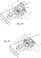
- Figs. 34 and 35 illustrate another method of using the described clamp assembly 10 according to the present invention.
- the mounting element 18 is secured to a support structure 14 by way of a bolt 50 or other suitable fastener.
- a bundle 12 is placed on arcuate profile 20B and clamp member 16A is moved as shown in Fig. 29 such that the arcuate tongue 34 and its serrations 42 are engaged by the engaging pawl 38 in the slot opening 36 until a proper tension is achieved and the bundle 12 is secured.
- the method shown in Figs. 34 and 35 may include the further step of retaining the clamp member 16 with a cable tie 74.
- such cable tie 74 include a head 78 and a flexible strap 79, which terminates in a tail 80.
- the cable tie 74 is inserted through the head 78 and then looped around the elongate item, in this use the clamp member 16.
- the tail 80 is then pulled tight to pull the strap 79 around the clamp member 16 to thereby secure the clamp member 16 in a closed position.
- a pawl mechanism (not shown) within the head 78 secures the strap 79 against withdrawal.
- the use of the cable tie 74 further secures the clamp member 16 in closed condition the event of a failure or other unwanted release of the clamp member 16, see Figs. 35A and 35B .
- the remaining portion of the adjustable P-clamp may be used as a saddle mount by using a flexible cable tie to secure the bundle against the saddle mount base as shown in Fig 35A and 35B .
- This is beneficial for customers trying to provide a quick repair of a broken adjustable P-clamp.
- an over-the-road truck driver making an emergency repair of a leaking hydraulic hose may accidentally sever the hinge of the adjustable P-clamp while removing the failed hose.
- the truck driver could successfully secure the new hydraulic hose to the remaining portion of the adjustable P-clamp using a standard cable tie which widely available at a truck stop.
- the adjustable P-clamp by having an inherently flexible design and being formed of impact resistant polymer material, provides isolation and/or vibration dampening for elongate bundles, i.e.; cables, wires, harnesses, hoses, tubing, etc., in comparison to metal P-clamps which does not provide vibration dampening. Vibration dampening reduces the incidence of fatigue failures that occur on non-flexible components that are allowed to vibrate at harmonic frequencies. For example, when metal brake lines vibrate on automobiles at highway speeds, the metal P-clamps that retain the brake lines also vibrate. In this case, without flexible plastic components periodically installed, fatigue failures can occur at brake line connections and on the metal P-clamps.
- a tension tab 62 may comprise an elongate strap portion 64 and a head portion (not shown).
- a tension tab 62 may be used to aid the installer in a controlled closing of the clamp members 16A, 16B around the bundle 12 and to apply proper, accurate tensioning of the clamp members 16A, 16B around the bundle 12.
- the mounting element 18 is secured to a support structure 14 by way of a bolt 50.
- a bundle 12 is placed on arcuate profile 20B and the tension tab 62 is inserted in a tension tab aperture 68 on the adjustable P-clamp 10.
- the head portion is stopped against an abutment 70 in the tension tab aperture 68, see Fig. 24 , while the strap portion 64 extends from the tension tab aperture 68.
- a handheld tensioning and cutoff tool 72 grasps the strap portion 64 and the handheld tensioning and cutoff tool 72 is actuated to pull the strap portion 64 in the direction of arrow A, also see Fig. 24 .
- the handheld tensioning and cutoff tool 72 pushes against the first clamp member 16A in the direction of arrow B to thereby close the clamp members 16A, 16B with a predetermined tension such that the arcuate tongue 34 and its serrations 42 are engaged by the pawl 38 in the slot opening 36 until a proper tension is achieved and the bundle 12 is secured.
- a clamp assembly 10 may be provided with a saddle mount 82.
- a saddle mount 82 may be seen attached to the clamp member 16A and including a tie slot 84.
- the saddle mount 82 may support a bundle 12 which is secured by a cable tie 74. As shown, the cable tie 74 encircles the bundle 12, is received by the tie slot 84, and thereby attaches the bundle 12 to the saddle mount 82.
- a saddle mount 82 is shown in conjunction with the adjustable P-clamp 10 illustrated in Figs. 37 through 39 , clamp assemblies 10, 10A depicted in other figures may also include a saddle mount 82.
- the saddle mount 82 provides the benefit of securing separated parallel bundles to the adjustable P-clamp 10.
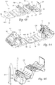
- Figs. 40 through 42 illustrate another embodiment of a clamp assembly 10B according to the present invention which combines previously described features.
- the adjustable P-clamp 10B of these views includes an integrally formed clamp member 16 and a mounting element 18, the clamp member 16 having a pair of locking clamp members 16A, 16B each defining an arcuate profile 20A, 20B.
- the arcuate profiles 20A, 20B may further include ridges 21 projecting from the arcuate profiles 20A, 20B to aid in securing a bundle 12 (not shown in these views) within the clamp member 16 and help prevent unwanted rotation of the bundle 12 during vibration or other movement of the adjustable P-clamp 10B.
- the adjustable P-clamp 10B of these views may include a cradle member 58.
- a hinge mechanism 22 may include an area of reduced thickness 24 to allow the hinge mechanism 22 to move freely during the installation and securing of a bundle 12.
- the hinge mechanism 22 may include a hinge interlocking mechanism 26 in which the arcuate projection 28 is configured for reception into a corresponding channel 30.
- the embodiment illustrated in Figs. 40 through 42 further includes a lock mechanism 32 similar to that of previous embodiments, wherein the lock mechanism 32 is comprised of a arcuate tongue 34 and a slot opening 36 having an engaging pawl 38.
- the pawl 38 may include a wedge release aid 86 as was described with reference to Figs. 33A and 33B .
- the protruding beam 40 of a first clamp member 16A may include an extending arcuate tongue 34, with a slot opening 36 being positioned adjacent a second arcuate profile 20B.
- the arcuate tongue 34 is preferably molded with a plurality of serrations 42, which extend along the length of the arcuate tongue 34 and across the width of the arcuate tongue 34.
- the serrations 42 may be arranged in two parallel rows as shown, with the wedge release aid 86 positioned between the rows of serrations 42.
- the arcuate tongue 34 is adapted to be received in a corresponding slot opening 36 adjacent the second arcuate profile 20B.
- the engaging pawl 38 located in the slot opening 36 may include teeth 44 arranged in two parallel rows to correspond to the width of the serrations 42 on the arcuate tongue 34.
- the serrations 42 engage the teeth 44 on the engaging pawl 38 when the arcuate tongue 34 is inserted into the slot opening 36 for retaining the bundle 12.
- the arcuate tongue 34 may further include a pair of spaced apart serration rails 43 to minimize damage to the serrations 42 by a release tool 76, see Figs. 32, 33A, and 33B , should opening of the lock mechanism 32 be desired.
- the arcuate tongue 34 may be reinforced by way of the flanges 92 illustrated. The flanges 92 reduce twisting or buckling of the arcuate tongue 34 in use.
- the mounting member 46 of the embodiment shown may be overmolded.
- Figs. 43 and 44 illustrate a variation of the adjustable P-clamp 10B featured in Figs. 40 through 42 .
- the adjustable P-clamp of these views includes an over molded mounting member 46B having flattened profile portions 88.
- the flattened profile portions 88 allow nesting of two clamp assemblies 10B, as is illustrated in Fig. 43 .
- the flattened profile portions 88 of the mounting members 46B nest against stepped portions 54 of a corresponding clamp assembly 10B, thereby allowing facile use of multiple adjacent clamp assemblies 10B.
- the embodiment in Figs. 45 through 48 illustrates an alternative clamp assembly 10C featuring a variation of the tension tab mount 100 as featured in all previous embodiments.
- the tension tab mount 100 is comprised of a plurality of substantially symmetrical tab mount flanges 102 having an inner face 104 and an outer face 106.
- the tab mount flanges 102 are spaced apart the approximately the width of the tension tab 62.
- To mount the tension tab 62 the user glidingly inserts the tension tab 62 in between the tab mount flanges 102 tangentially contacting the inner faces 104. And the tension tab 62 is locked in place by the tab securing wedge 108.
- To dismount the user applies pressure to the outer face 106 and the tab securing wedge 108 to dislodge the tension tab 62.
- the illustrated embodiment features a clamp mounting attachment 110 for purposes of mounting the adjustable P-clamp on a surface using an adhesive pad 124 and adhesive surface 116.
- the clamp mounting attachment 110 is horizontally guided into the mounting insert channel 130 of the adjustable P-clamp, wherein the upper surface 112 of the clamp mounting attachment 110 is guided and frictionally engages with the upper channel surface 130A; the substantially symmetrical and mirrored channel wings 132 frictionally engage with the mounting attachment's groove surface 122 and mid surface 118 to keep the clamp mounting attachment 110 in guided position within the mounting insert channel 130.
- the curved wedge clip face 120A is guided under the channel wedge 126 and the wedge clip 120 is secured on the outer face of the wedge clip 126A.
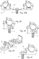
- Figs. 49 through 52 feature multiple configurations of the clamp mounting attachment 110 to be used with various mounting approaches.
- Fig. 49 illustrates the mounting configured with a mounting arrowhead 140.
- Fig. 50 illustrates the mounting attachment configured with a mounting fir tree 150.
- Fig. 51 illustrates the mounting attachment configured with a mounting oval fir tree 160.
- Fig. 52 illustrates the mounting attachment configured with a mounting edge clip 170.
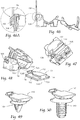
- Figs. 55A and 55B illustrate another variation of the clamp mounting assembly.
- the adjustable P-clamp of these views includes a groove member 200 having an elevated lip member 200A.
- the elevated lip member 200A allow the outer lips of the adjustable P-clamp 10C to nestle into the grooves of the groove member 200, thereby allowing facile use of multiple adjacent clamp assemblies 10C.
- Figs. 56A, 56B , and 58 illustrate another variation of the clamp mounting assembly.
- the adjustable P-clamp of these views includes a molded lip member 210 allowing for the outer lips of the adjustable P-clamp 10C to nestle into the grooves of the lip member 210, thereby allowing facile use of multiple adjacent clamp assemblies 10C.
- the lip member 210 is formed to house a mounting aperture 48 sized and dimensioned to receive an attachment feature, such as a bolt 50.
- Figs. 57A , 57B, and 59 illustrate another variation of the adjustable P-clamp.
- the adjustable P-clamp of these views includes a mounting member 220 and mirrored lip wings 224.
- the lip wings 224 allow the outer lips of the adjustable P-clamp 10C to nestle under the grooves to lock maintain firm position on the adjustable P-clamp, as is illustrated in Fig. 57B .
- the mounting member 220 lip member 210 is formed to house a mounting aperture 48 sized and dimensioned to receive an attachment feature, such as a bolt 50.
- Figs. 60 and 61 illustrate clamp assembly 10C also having mounting element 18 for securing clamp-restrained elongated articles or bundles 12 to a support structure 14.
- 'One or more' includes a function being performed by one element, a function being performed by more than one element, e.g., in a distributed fashion, several functions being performed by one element, several functions being performed by several elements, or any combination of the above.
- substantially parallel means ⁇ 15°of absolutely parallel
- substantially perpendicular means ⁇ 15°of absolutely perpendicular.
Abstract
Description
- The present invention relates generally to retaining mechanisms. Particularly, the present invention is directed to an offset mounted clamp whereby an elongate bundle is secured and offset a distance from the mounting hole.
- The present invention will now be described, by way of example with reference to the accompanying drawings, in which:
-
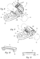
Fig. 1 is a perspective view of a P-clamp according to the prior art; -
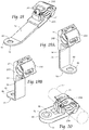
Fig. 2 is a perspective view of an adjustable P-clamp according to an embodiment of the invention; -
Fig. 3 is a top view of the adjustable P-clamp illustrated inFig. 2 according to an embodiment of the invention; -
Fig. 4 is a side elevation view of the adjustable P-clamp shown inFigs. 2 and 3 according to an embodiment of the invention; -
Fig. 5 is a cross section view of the adjustable P-clamp illustrated inFigs. 2 through 4 and taken along lines 5 - 5 ofFig. 3 according to an embodiment of the invention; -
Fig. 6 is a fragmentary enlarged view of the adjustable P-clamp illustrated inFig. 2 through 5 and showing the hinge portion according to an embodiment of the invention; -
Fig. 7 is a fragmentary enlarged view of the clamp illustrated inFig. 2 through 5 and showing the locking pawls according to an embodiment of the invention; -
Fig. 8 is a view similar to that ofFig. 2 , but showing the clamp being positioned for fastening around an elongate object according to an embodiment of the invention; -
Fig. 9 is a view similar to that ofFig. 8 , but showing the clamp fastened around an elongate object according to an embodiment of the invention; -
Fig. 10 is a perspective view of a flexible cradle insert according to an embodiment of the invention; -
Fig. 11 is a side view of the insert illustrated inFig. 10 according to an embodiment of the invention; -
Fig. 12 is a perspective view of an assembly, similar to that ofFig. 2 , but showing flexible cradle inserts in place on the clamping portion according to an embodiment of the invention; -
Fig. 13 is a perspective view of an assembly, similar to that shown inFig. 9 , but showing a fastening tab having a non-reinforced opening according to an embodiment of the invention; -
Fig. 14 is a perspective view of an assembly, similar to that shown inFig. 13 , but showing a metal fastening tab according to an embodiment of the invention; -
Fig. 14A is a perspective view of the adjustable P-clamp illustrated inFig. 14 , but showing a cable tie in use to secure an elongate object after clamp failure according to an embodiment of the invention; -
Fig. 15 is a perspective view of an assembly, similar to that shown inFigs. 13 and 14 , but showing a fastening tab having an angled portion according to an embodiment of the invention; -
Fig. 16A is a perspective view of an alternative arrangement wherein a metal positioning bracket includes an over molded saddle or slot to receive a cable tie to secure an elongate object without use of a P-clamp according to an embodiment of the invention; -
Fig. 16B is a side view of the device shown inFig. 16A according to an embodiment of the invention; -
Fig. 17 is a perspective view of an assembly, similar to that shown inFigs. 13, 14 , and15 , but showing a fastening tab having an extended and angled portion according to an embodiment of the invention; -
Fig. 18 is a perspective view of an assembly, similar to that shown inFig. 17 , but showing a fastening tab having an extended and angled portion according to an embodiment of the invention; -
Fig. 19A is a perspective view of an assembly, similar to that shown inFigs. 15, 17 , and18 , but showing the fastening tab having an extended arm portion and an angled portion extending at a 90° angle in a first direction according to an embodiment of the invention; -
Fig. 19B is a perspective view of an assembly, similar to that shown inFigs. 15, 17 , and18 , but showing the fastening tab having an extended arm portion and an angled portion extending at a 90° angle in a second direction according to an embodiment of the invention; -
Fig. 20 is a view similar to that ofFig. 9 , but showing a cable tie further securing the clamp in a closed position according to an embodiment of the invention; -
Fig. 21 is a perspective view of a tension tab for use with the present invention according to an embodiment of the invention; -
Fig. 22 is a view similar to that ofFig. 12 , but showing a tension tab mount and a tension tab in place for use according to an embodiment of the invention; -
Fig. 23 is a front perspective view of the adjustable P-clamp and tension tab illustrated inFig. 22 and showing an elongate groove to guide the tension tab according to an embodiment of the invention; -
Fig. 24 is a partial cut away side view of the assembly and tension tab illustrated inFigs. 12 and22 , but showing the tension tab being tightened by a hand held device according to an embodiment of the invention; -
Fig. 25 is a side elevation view of another embodiment of an assembly and showing two P-clamps joined by a single fastening tab according to an embodiment of the invention; -
Fig. 26 is a view similar to that ofFig. 25 but showing two P-clamps joined by a metal fastening tab according to an embodiment of the invention; -
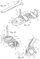
Fig. 27 is a perspective view of an assembly similar to that illustrated inFig. 2 , but showing a bolt fastening the adjustable P-clamp to a support surface according to an embodiment of the invention; -
Fig. 28 is a view similar to that ofFig. 27 , but showing the adjustable P-clamp secured to a support surface and ready to receive an elongate object according to an embodiment of the invention; -
Fig. 29 is a view similar to that ofFigs. 27 and28 but showing the adjustable P-clamp secured to a support surface and the P-clamp being positioned for fastening around an elongate object according to an embodiment of the invention; -
Fig. 30 is a view similar to that ofFigs. 27 through 29 , but showing the P-clamp fastened around an elongate object according to an embodiment of the invention; -
Fig. 31 is a partially cut away side elevation view of the adjustable P-clamp illustrated inFig. 30 and showing a locking mechanism securing the P-clamp around an elongate object -
Fig. 32 is a view similar to that ofFig. 31 but showing a tool releasing the locking mechanism to open the P-clamp according to an embodiment of the invention; -
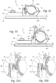
Figs. 33A and 33B are enlarged views showing a portion ofFig. 32 with a tool releasing the locking mechanism to open the P-clamp according to an embodiment of the invention; -
Fig. 34 is a view similar to that ofFig. 30 , but showing a cable tie being positioned around the P-clamp according to an embodiment of the invention; -
Fig. 35 is a view similar to that ofFig. 34 , but showing a cable tie in place and securing the P-clamp around an elongate object according to an embodiment of the invention; -
Fig. 35A is a perspective view of an assembly, similar to that shown inFig. 35 , but showing a cable tie in use to secure an elongate object during clamp failure according to an embodiment of the invention; -
Fig. 35B is a cross section view of the adjustable P-clamp illustrated inFig. 35A and taken alongline 35B - 35B thereof according to an embodiment of the invention; -
Fig. 36 is a view similar to that ofFig. 22 , but showing the adjustable P-clamp secured to a support surface and with a tension tab in place in the tension tab mount according to an embodiment of the invention; -
Fig. 37 is a side elevation view of the adjustable P-clamp illustrated inFig. 36 and showing the tension tab being tightened by a hand held device according to an embodiment of the invention; -
Fig. 38 is a view of the adjustable P-clamp illustrated inFig. 37 but with the tension tab fully tightened, the P-clamp is closed and secured around an elongate object, and the tension tab tail severed according to an embodiment of the invention; -
Fig. 39 is a perspective view of an assembly similar to that illustrated inFig. 8 , but showing a second bundle attached to a saddle mount according to an embodiment of the invention; -
Fig. 40 is a is a perspective view of an assembly, similar to that ofFig. 2 , but having a metal fastening tab in combination with a tension tab aperture according to an embodiment of the invention; -
Fig. 41 is another perspective view of the adjustable P-clamp illustrated inFig. 40 according to an embodiment of the invention; -
Fig. 42 is another perspective view of the adjustable P-clamp illustrated inFigs. 40 and 41 , but showing the P-clamp in a closed position according to an embodiment of the invention; -
Fig. 43 is a perspective view of an alternative assembly, similar to that shown inFig. 40 , but having a metal fastening tab with flattened portions according to an embodiment of the invention; -
Fig. 44 is a perspective view showing two assemblies as illustrated inFig. 43 with the flattened portions of metal fastening tabs nested against stepped portions according to an embodiment of the invention; -
Fig. 45 is a perspective view of an alternate assembly and showing a tension tab lock and a tension tab in place for use according to an embodiment of the invention; -
Fig. 46 is a side view showing a tension tab lock and tension tab illustrated inFig. 45 according to an embodiment of the invention; -
Fig. 46A is an enlarged view showing a portion ofFig. 46 with a tension tab lock and tension tab according to an embodiment of the invention; -
Fig. 47 is a bottom perspective view ofFig. 45 showing a mounting insert channel according to an embodiment of the invention; -
Fig. 48 is a perspective view showing an assembly as illustrated inFigs. 45 and46 , but showing the mounting insert as it is to be positioned in the insert channel according to an embodiment of the invention; -
Fig. 49 is a perspective view of a variation of the mounting insert as illustrated inFig. 48 , configured with a mounting arrowhead according to an embodiment of the invention; -
Fig. 50 is a perspective view of a variation of the mounting insert as illustrated inFig. 48 , configured with a mounting fir tree according to an embodiment of the invention; -
Fig. 51 is a perspective view of a variation of the mounting insert as illustrated inFig. 48 , configured with a mounting oval fir tree according to an embodiment of the invention; -
Fig. 52 is a perspective view of a variation of the mounting insert as illustrated inFig. 48 , configured with a mounting edge clip according to an embodiment of the invention; -
Fig. 53 is a front elevation view of an assembly as illustrated inFigs. 45 through 48 and showing a partial sectional view of the mounting insert positioned in the mounting channel according to an embodiment of the invention; -
Fig. 54 is a side elevation view of an assembly as illustrated inFigs. 45 through 48 showing the mounting insert positioned in the mounting channel according to an embodiment of the invention; -
Fig. 55A is a perspective view of variation of a mounting assembly having two mounting inserts as illustrated inFig. 48 according to an embodiment of the invention; -
Fig. 55B is a front view ofFig. 55A , showing two assemblies as illustrated inFig. 45 affixed with the mounting inserts positioned in the mounting channels according to an embodiment of the invention; -
Fig. 56A is a perspective view of a variation of the mounting assembly as illustrated inFig. 55A , having a mounting aperture sized and dimensioned to receive an attachment feature, such as a bolt according to an embodiment of the invention; -
Fig. 56B is a front view ofFig. 56A , showing two assemblies as illustrated inFig. 45 affixed with the mounting inserts positioned in the mounting channels and a bolt positioned in the mounting aperture according to an embodiment of the invention; -
Fig. 57A is a perspective view of a variation of a mounting assembly having two mounting inserts as illustrated inFigs. 56A and 56B , having a mounting aperture sized and dimensioned to receive an attachment feature, such as a bolt according to an embodiment of the invention; -
Fig. 57B is a front elevation view ofFig. 57A , showing two assemblies as illustrated inFig. 45 affixed with the mounting inserts positioned in the mounting channels and a bolt positioned in the mounting aperture according to an embodiment of the invention; -
Fig. 58 is a side elevation view of a mounting assembly as illustrated inFigs. 56A and 56B with showing a partial sectional view of the mounting insert positioned in the mounting channel as well as the bolt positioned in the mounting aperture according to an embodiment of the invention; -
Fig. 59 is a side elevation view of a mounting assembly as illustrated inFigs. 57A and57B with showing a partial sectional view of the mounting insert positioned in the mounting channel as well as the bolt positioned in the mounting aperture according to an embodiment of the invention; -
Fig. 60 is a perspective view of a variation of the P-clamp shown inFig. 45 view showing a tension tab lock and tension tab illustrated inFig. 45 , but showing a mounting aperture to receive a bolt according to an embodiment of the invention; and -
Fig. 61 is a side view ofFig. 60 , showing a bolt positioned in the mounting aperture according to an embodiment of the invention. - Although the disclosure hereof is detailed and exact to enable those skilled in the art to practice the invention, the physical embodiments herein disclosed merely exemplify the invention which may be embodied in other specific structures. While the preferred embodiment has been described, the details may be changed without departing from the invention.
- Referring to the drawings and in particular to
Figs. 2 through 9 , inclusive, a non-limiting example of adevice 10 that is configured to adjustably attach an elongate item to a support structure is shown. Thedevice 10 very closely resembles a "P-clamp" and is hereinafter referred to as an adjustable P-clamp 10. The adjustable P-clamp 10 functions to secure elongate items, such as wires, cables and the like intobundles 12, shown in phantom lines, and to further secure thebundles 12 to anadjacent support structure 14, seeFig. 27 for an example. It will be apparent that thebundle 12 may comprise a single object or several objects, such as wires, conduits, or cables that are flexible or rigid, hot or cold, or fluid transporting hoses or tubes, fiber optics, conduits, plant vines, etc. Some elongate items may also be contained within the bore of a conventional tubular conduit. The adjustable P-clamp 10 is particularly well suited for use in applications requiring releasable clamping while the adjustable P-clamp 10 is attached to asupport structure 14. - As illustrated in the view of
Fig. 2 , the adjustable P-clamp 10 includes two principal components, namely an integrally formedclamp member 16 and a mountingelement 18. Theclamp members profiles arcuate profiles bundle 12 and are joined by ahinge mechanism 22. Thearcuate profiles ridges 21 projecting from thearcuate profiles ridges 21 aid in securing abundle 12 within theclamp member 16 and help prevent unwanted rotation of thebundle 12 during vibration or other movement of the adjustable P-clamp 10. Alternatively, theclamp members cradle member 58, as will be discussed with reference toFigs. 10 through 12 . As may be seen inFig. 4 , thehinge mechanism 22 may include an area of reducedthickness 24 which allows thehinge mechanism 22 to flex or bend freely during the installation and securing of abundle 12. This type of hinge mechanism may be referred to as a living hinge. Alternative embodiments may be envisioned using other types of hinge mechanisms, such as a piano hinge, a butt hinge, etc. The hinge mechanism provides the benefit of maintaining alignment of thearcuate tongue 34 with theslot opening 36 throughout the process of closing thefirst clamp member 16A around thebundle 12. - With specific reference to
Figs. 5 and 6 , it may be seen that thehinge mechanism 22 may also include ahinge interlocking mechanism 26. As shown, the interlockingmechanism 26 comprises anarcuate projection 28 that is configured to be received into a correspondingchannel 30. When theclamp member 16 is engaged, and theclamp members bundle 12, as will be described, the interaction of the interlockingarcuate projection 28 in thechannel 30 provides a secondary retention across the hinge which would be required in the unlikely event the area of reduced thickness in thehinge mechanism 22 would fail, due to cracking or other failure, thereby retaining theclamp members thickness 24 fail, due to cracking or other loss of function. Thehinge interlocking mechanism 26 may not be required, but provides backup retention and may be desired by consumers concerned about the robustness of plastic components. - As is illustrated in
Figs. 4, 5, 7 , and8 , theclamp member 16 may be seen to further include alock mechanism 32. Thelock mechanism 32 is comprised of anarcuate tongue 34 and aslot opening 36 having an engagingpawl 38, particularly seeFigs. 5 and 7 . As shown, a protrudingbeam 40 of the adjustable P-clamp 10 is positioned perpendicular to thearcuate tongue 34 and provides a platform or depression for an operators fingers or thumb press upon thefirst clamp member 16A when engaging thearcuate tongue 34 into theslot opening 36. Thefirst clamp member 16A may include an extendingarcuate tongue 34, with aslot opening 36 being positioned adjacent asecond clamp member 16B. Thearcuate tongue 34 is preferably molded with a plurality ofserrations 42, which extend along the length of thearcuate tongue 34 and across the width of thearcuate tongue 34. Theserrations 42 may be arranged in two parallel rows as shown. Thearcuate tongue 34 is adapted to be received in a corresponding slot opening 36 adjacent the secondarcuate profile 20B. As may be seen particularly inFigs. 5 and 7 , the engagingpawl 38 located in theslot opening 36 may includeteeth 44 thereon. Theteeth 44 may be arranged in two parallel rows to correspond to the width of theserrations 42 on thearcuate tongue 34. As illustrated, theserrations 42 engage theteeth 44 on the engagingpawl 38 when thearcuate tongue 34 is inserted into theslot opening 36 for retaining thebundle 12. As best shown inFigs. 8 and 9 , thearcuate tongue 34 may further include a pair of spaced apart serration rails 43. The pair of spaced apart serration rails 43 serve to protect theserrations 42 from damage from arelease tool 76, seeFig. 32 , should opening of thelock mechanism 32 be desired. The leading edge of thearcuate tongue 34 may be chamfered to provide the benefit of more easily inserting thearcuate tongue 34 into theslot opening 36. - The adjustable P-
clamp 10 is adjustable to secure a range of various bundle diameters. Each succeeding engagement of thepawl teeth 44 to theserrations 42 reduces the circumferential diameter being formed by the adjustable P-clamp 10. Therefore, the adjustable P-clamp 10 is adjustable to various elongate bundle diameters within a predefined range designed for each size of adjustable P-clamp 10. - The protruding
beam 40 of the adjustable P-clamp 10 is positioned perpendicular to thearcuate tongue 34 and provides a platform or depression for an operators fingers or thumb press upon thefirst clamp member 16A when engaging thearcuate tongue 34 into theslot opening 36. - With reference to
Figs. 10 and 11 , acradle member 58 may be seen. Thecradle member 58 is adapted for engagement withrespective clamp members secured bundle 12 during use. Thecradle member 58 may be fabricated of rubber or other high coefficient of friction material, to thereby provide a gripping force on asecured bundle 12 and to prevent unwanted rotation of asecured bundle 12 in applications during which vibration or other movement of the adjustable P-clamp 10 may occur. Thecradle member 58 may includeflanges 60 for securement torespective clamp members - As mentioned, a
clamp assembly 10 according to the present invention further includes a mountingelement 18 for securing clamp-restrained elongated articles orbundles 12 to asupport structure 14. As seen in the figures, the mountingelement 18 includes an extending mountingmember 46 having a mountingaperture 48 therein. The mountingaperture 48 is preferably sized and dimensioned to receive an attachment feature, such as thebolt 50 shown, seeFigs. 27 through 38 , although it is to be understood that other attachment feature may be used to attach the adjustable P-clamp 10 to aprimary support structure 14, such as screws, or other known fastening devices. The mountingmember 46 may be integrally formed with the adjustable P-clamp 10, as is shown inFigs. 2 through 13 or may be over molded with the adjustable P-clamp as depicted inFigs. 14 ,15 , and17 through 19A /B . The mountingmember 46 may be fabricated of any suitably resilient material, including molded polymer, as seen inFig. 2 and others, or metal as seen inFig. 14 and others. Ametal mounting member 46 can withstand high torque installation of fasteners, e.g. nuts, bolts, etc., and the over molded plasticsecond clamp member 16B provides some vibration dampening and/or isolation. - Moreover, the mounting
aperture 48 may include anaperture reinforcement member 52, as is shown inFigs. 2 through 12 , or may lack such a feature as is shown inFigs. 13 through 15 andFigs. 17 through 19A /B as may be desired by the specific application. Further, a mountingmember 46A may be used without aclamp member 16, as is shown inFigs. 16A and 16B , wherein the mountingmember 46A includes atab slot 90 to receive acable tie 74 to pass through and around the adjustable P-clamp and interact and further secure the adjustable P-clamp in a closed position. The mountingmember 46A may be planar or angled to position the mountingmember 46A at an optimal location and orientation for routing of thebundle 12. The mountingmember 46A may be formed of metal and include a plastic over moldedportion 91 surrounding the atab slot 90 to prevent contact between thebundle 12 with a metal portion of the mountingmember 46A. The mountingmember 46A provides the benefit of retaining thebundle 12 without metal components being used to circumferentially compress and retain the bundle. No metal components are in direct contact with bundle. Metal in contact with bundles is known to adversely cause detrimental damage to bundles, e.g. harnesses, cables, hoses, etc. - As may be seen in
Figs. 13 through 19A /B, the mountingmember member 46 may extend laterally in a generally planar arrangement, seeFig. 13 , may include a stepped portion 54 (seeFig. 14 ), or may extend at an angle, seeFig. 15 . Moreover, the mountingmember 46 may include anextension portion 56, seeFigs. 17 and18 , having a predetermined length. The length of theextension portion 56 may vary according the requirements of a specific application. Theextension portion 56 provides the benefit of positioning theclamp member 16 to extend, reach guide, and route thebundle 12 in applications where a mounting hole or treaded stud is not available in close proximity to thebundle 12. - Moreover, the mounting
member 46 may be integrally formed as a one piece construction with the adjustable P-clamp 10, as seen inFig. 13 , may be overmolded as is shown inFigs. 14 , and17 through 19A /B , or may be a unitary piece without aclamp member 16 as shown inFigs. 16A and 16B . - The wedge-shaped pawl may have two separate segmented rows of teeth with a large enough gap between the rows of teeth to allow a small screw driver to be inserted in between the rows of teeth for releasing engagement of the pawl. A complementary gap exists between the serrations on the tongue: One embodiment similarly segments the tongue serrations resulting in a similar gap that was discussed on the wedge shaped pawl. The resulting gap is in the center of the tongue to likewise allow the small screwdriver to be inserted in between serrations for release of adjustable P-clamp, unimpeded by the serrations, and being less likely to damage the serrations with the screwdriver during the release process. Another embodiment adds tall rails to the edges of the gap forming separation walls perpendicularly flanking the serrations zones, thereby creating a release channel for the screwdriver making it less likely to be able to damage the serrations with screwdriver during release of the adjustable P-clamp.
- Thus the above mentioned features provide an easy to release bundle retention feature that allows the clamp to be reused and is attributed to the damage prevention features, i.e. a gap for unimpeded screwdriver entry and a channel to control screwdriver movement and inhibit screwdriver deflection.
- With reference now to
Figs. 21 through 24 , thepresent clamp assembly 10 may be seen in use in combination with atension tab 62. Atension tab 62 for use with thepresent clamp assembly 10 may comprise anelongate strap portion 64 and a T-shapedhead portion 66. Atension tab 62 may be used to aid a user in closing theclamp members elongate bundle 12, and to apply proper tension of theclamp members bundle 12. In use, and as seen inFig. 24 , thetension tab 62 is inserted in atension tab aperture 68 on the adjustable P-clamp 10. The -shapedhead portion 66 is stopped against anabutment 70 in thetension tab aperture 68, while thestrap portion 64 extends from thetension tab aperture 68, seeFig. 24 . To close theclamp members bundle 12, the user may press down on thefirst clamp member 16A to move thearcuate tongue 34 into theslot opening 36, or, when thetension tab 62 is used, the user may use a handheld tensioning andcutoff tool 72 to grasp thestrap portion 64. When thetension tab 62 and the handheld tensioning andcutoff tool 72 are used as shown inFig. 24 , the handheld tensioning andcutoff tool 72 is actuated to pull thestrap portion 64 in the direction of arrow A, while pushing against thefirst clamp member 16A in the direction of arrow B to thereby close theclamp members cutoff tool 72. Once closed to the predetermined tension, the handheld tensioning andcutoff tool 72 may severe the excess portion of thestrap portion 64. Thepresent clamp assembly 10 may be further used on combination with aflexible cable tie 74, seeFig. 20 , such as are widely used in other applications to secure elongate items, such as wires, cables, hoses and tubes, into compact, secure bundles, as will be discussed. - The views of
Figs. 25 and 26 illustrate an alternativeembodiment clamp assembly 10A, in which a pair ofclamp members element 18A. As in the previously described embodiment, the adjustable P-clamp 10A of these views includes two principal components, a pair of integrally formedclamp members element 18A. Theclamp members profiles bundle 12 and are joined by ahinge mechanism 22. Thearcuate profiles ridges 21 projecting from thearcuate profiles clamp members cradle member 58, as described with reference toFigs. 10 and 11 . As in the previously described embodiment, thehinge mechanism 22 may include an area of reducedthickness 24 to allow thehinge mechanism 22 to move freely during the installation and securing of abundle 12. The adjustable P-clamp 10A illustrated in these views further includes thehinge interlocking mechanism 26 previously discussed as comprises thearcuate projection 28 that is configured to be received into a corresponding channel 30 (not shown in these views). Moreover, the adjustable P-clamp 10A illustrated inFigs. 25 and 26 includes a mountingelement 18A for securing clamp-restrained elongated articles orbundles 12 to asupport structure 14, seeFigs. 27 through 38 . As in the previous embodiment, the mountingelement 18A includes an extending mountingmember 46 having a mountingaperture 48 therein which may or may not include anaperture reinforcement member 52. The mountingmember 46 may be integrally formed with the adjustable P-clamp 10A, as is shown inFig. 25 or may be over molded with the adjustable P-clamp 10A as depicted inFig. 26 . - A method of using the described
clamp assembly 10 according to the present invention may be seen inFigs. 27 through 33B . As is shown, the mountingelement 18 of the adjustable P-clamp 10 is secured to asupport structure 14 by way of thebolt 50 shown, although it is to be understood that other attachment feature may be used to attach the adjustable P-clamp 10 to aprimary support structure 14, such as screws, or other known fastening devices. Abundle 12 is placed onarcuate profile 20B and clampmember 16A is moved in the direction of arrow C, seeFig. 29 . Asclamp member 16A moves around bundle 12, thearcuate tongue 34 and itsserrations 42, are engaged by the engagingpawl 38 in theslot opening 36 until a proper tension is achieved and thebundle 12 is secured. In the event that release of thebundle 12 is desired, anelongate release tool 76 is inserted into theslot opening 36, as shown inFigs. 32 through 33B . Therelease tool 76 biases the engagingpawl 38 such theteeth 44 on the engagingpawl 38 disengage from theserrations 42 of thearcuate tongue 34, and thearcuate tongue 34 may be released in the direction of arrow D, thereby opening theclamp member 16 and freeing thebundle 12. Moreover, the views ofFigs. 33A and 33B illustrate the engagingpawl 38 having awedge release aid 86 to further aid a user in release of thearcuate tongue 34. As shown, arelease tool 76 moves in the direction of arrow E and biases thewedge release aid 86 for release of thearcuate tongue 34 in the direction of arrow D, seeFig. 32 . -
Figs. 34 and 35 illustrate another method of using the describedclamp assembly 10 according to the present invention. As is shown, and similar to the method ofFigs. 28 through 31 , the mountingelement 18 is secured to asupport structure 14 by way of abolt 50 or other suitable fastener. Abundle 12 is placed onarcuate profile 20B and clampmember 16A is moved as shown inFig. 29 such that thearcuate tongue 34 and itsserrations 42 are engaged by the engagingpawl 38 in theslot opening 36 until a proper tension is achieved and thebundle 12 is secured. The method shown inFigs. 34 and 35 may include the further step of retaining theclamp member 16 with acable tie 74. Typically,such cable tie 74 include ahead 78 and aflexible strap 79, which terminates in atail 80. In use, thecable tie 74 is inserted through thehead 78 and then looped around the elongate item, in this use theclamp member 16. Thetail 80 is then pulled tight to pull thestrap 79 around theclamp member 16 to thereby secure theclamp member 16 in a closed position. A pawl mechanism (not shown) within thehead 78 secures thestrap 79 against withdrawal. The use of thecable tie 74 further secures theclamp member 16 in closed condition the event of a failure or other unwanted release of theclamp member 16, seeFigs. 35A and 35B . - In the unlikely event that the hinge mechanism fractures and the
clamp members 16A becomes detached or lost, the remaining portion of the adjustable P-clamp may be used as a saddle mount by using a flexible cable tie to secure the bundle against the saddle mount base as shown inFig 35A and 35B . This is beneficial for customers trying to provide a quick repair of a broken adjustable P-clamp. For example, an over-the-road truck driver making an emergency repair of a leaking hydraulic hose may accidentally sever the hinge of the adjustable P-clamp while removing the failed hose. The truck driver could successfully secure the new hydraulic hose to the remaining portion of the adjustable P-clamp using a standard cable tie which widely available at a truck stop. - Further, the adjustable P-clamp, by having an inherently flexible design and being formed of impact resistant polymer material, provides isolation and/or vibration dampening for elongate bundles, i.e.; cables, wires, harnesses, hoses, tubing, etc., in comparison to metal P-clamps which does not provide vibration dampening. Vibration dampening reduces the incidence of fatigue failures that occur on non-flexible components that are allowed to vibrate at harmonic frequencies. For example, when metal brake lines vibrate on automobiles at highway speeds, the metal P-clamps that retain the brake lines also vibrate. In this case, without flexible plastic components periodically installed, fatigue failures can occur at brake line connections and on the metal P-clamps.
- Another method of using the described
clamp assembly 10 and utilizing atension tab 62 may be seen in the views ofFigs. 36 through 39 . Atension tab 62, as previously described, may comprise anelongate strap portion 64 and a head portion (not shown). Atension tab 62 may be used to aid the installer in a controlled closing of theclamp members bundle 12 and to apply proper, accurate tensioning of theclamp members bundle 12. As is shown, and similar to the methods ofFigs. 28 through 33B and34 through 35B , the mountingelement 18 is secured to asupport structure 14 by way of abolt 50. Abundle 12 is placed onarcuate profile 20B and thetension tab 62 is inserted in atension tab aperture 68 on the adjustable P-clamp 10. The head portion is stopped against anabutment 70 in thetension tab aperture 68, seeFig. 24 , while thestrap portion 64 extends from thetension tab aperture 68. A handheld tensioning andcutoff tool 72 grasps thestrap portion 64 and the handheld tensioning andcutoff tool 72 is actuated to pull thestrap portion 64 in the direction of arrow A, also seeFig. 24 . The handheld tensioning andcutoff tool 72 pushes against thefirst clamp member 16A in the direction of arrow B to thereby close theclamp members arcuate tongue 34 and itsserrations 42 are engaged by thepawl 38 in theslot opening 36 until a proper tension is achieved and thebundle 12 is secured. - As may further be seen in these views, a
clamp assembly 10 according to the present invention may be provided with asaddle mount 82. With particular attention toFig. 39 , asaddle mount 82 may be seen attached to theclamp member 16A and including atie slot 84. Thesaddle mount 82 may support abundle 12 which is secured by acable tie 74. As shown, thecable tie 74 encircles thebundle 12, is received by thetie slot 84, and thereby attaches thebundle 12 to thesaddle mount 82. It is to be understood that while asaddle mount 82 is shown in conjunction with the adjustable P-clamp 10 illustrated inFigs. 37 through 39 ,clamp assemblies saddle mount 82. Thesaddle mount 82 provides the benefit of securing separated parallel bundles to the adjustable P-clamp 10. - The views of
Figs. 40 through 42 illustrate another embodiment of aclamp assembly 10B according to the present invention which combines previously described features. As in other described embodiments, the adjustable P-clamp 10B of these views includes an integrally formedclamp member 16 and a mountingelement 18, theclamp member 16 having a pair of lockingclamp members arcuate profile arcuate profiles ridges 21 projecting from thearcuate profiles clamp member 16 and help prevent unwanted rotation of thebundle 12 during vibration or other movement of the adjustable P-clamp 10B. As with the previous embodiment, although not shown, the adjustable P-clamp 10B of these views may include acradle member 58. Moreover, ahinge mechanism 22 may include an area of reducedthickness 24 to allow thehinge mechanism 22 to move freely during the installation and securing of abundle 12. As further shown, and as also described in previous embodiments, thehinge mechanism 22 may include ahinge interlocking mechanism 26 in which thearcuate projection 28 is configured for reception into a correspondingchannel 30. - The embodiment illustrated in
Figs. 40 through 42 further includes alock mechanism 32 similar to that of previous embodiments, wherein thelock mechanism 32 is comprised of aarcuate tongue 34 and aslot opening 36 having an engagingpawl 38. Thepawl 38 may include awedge release aid 86 as was described with reference toFigs. 33A and 33B . As shown, the protrudingbeam 40 of afirst clamp member 16A may include an extendingarcuate tongue 34, with aslot opening 36 being positioned adjacent a secondarcuate profile 20B. Thearcuate tongue 34 is preferably molded with a plurality ofserrations 42, which extend along the length of thearcuate tongue 34 and across the width of thearcuate tongue 34. Theserrations 42 may be arranged in two parallel rows as shown, with thewedge release aid 86 positioned between the rows ofserrations 42. As previously mentioned, thearcuate tongue 34 is adapted to be received in a corresponding slot opening 36 adjacent the secondarcuate profile 20B. The engagingpawl 38 located in theslot opening 36 may includeteeth 44 arranged in two parallel rows to correspond to the width of theserrations 42 on thearcuate tongue 34. As in previous embodiments, theserrations 42 engage theteeth 44 on the engagingpawl 38 when thearcuate tongue 34 is inserted into theslot opening 36 for retaining thebundle 12. Thearcuate tongue 34 may further include a pair of spaced apart serration rails 43 to minimize damage to theserrations 42 by arelease tool 76, seeFigs. 32, 33A, and 33B , should opening of thelock mechanism 32 be desired. Thearcuate tongue 34 may be reinforced by way of theflanges 92 illustrated. Theflanges 92 reduce twisting or buckling of thearcuate tongue 34 in use. As illustrated, the mountingmember 46 of the embodiment shown may be overmolded. -
Figs. 43 and 44 illustrate a variation of the adjustable P-clamp 10B featured inFigs. 40 through 42 . The adjustable P-clamp of these views includes an over molded mountingmember 46B having flattenedprofile portions 88. The flattenedprofile portions 88 allow nesting of twoclamp assemblies 10B, as is illustrated inFig. 43 . As shown, the flattenedprofile portions 88 of the mountingmembers 46B nest against steppedportions 54 of acorresponding clamp assembly 10B, thereby allowing facile use of multipleadjacent clamp assemblies 10B. - The embodiment in
Figs. 45 through 48 illustrates analternative clamp assembly 10C featuring a variation of thetension tab mount 100 as featured in all previous embodiments. Thetension tab mount 100 is comprised of a plurality of substantially symmetricaltab mount flanges 102 having aninner face 104 and anouter face 106. Thetab mount flanges 102 are spaced apart the approximately the width of thetension tab 62. To mount thetension tab 62, the user glidingly inserts thetension tab 62 in between thetab mount flanges 102 tangentially contacting the inner faces 104. And thetension tab 62 is locked in place by thetab securing wedge 108. To dismount, the user applies pressure to theouter face 106 and thetab securing wedge 108 to dislodge thetension tab 62. - Regarding
Figs. 47, 48 and53 through 54 , the illustrated embodiment features aclamp mounting attachment 110 for purposes of mounting the adjustable P-clamp on a surface using anadhesive pad 124 andadhesive surface 116. Theclamp mounting attachment 110 is horizontally guided into the mountinginsert channel 130 of the adjustable P-clamp, wherein theupper surface 112 of theclamp mounting attachment 110 is guided and frictionally engages with theupper channel surface 130A; the substantially symmetrical and mirroredchannel wings 132 frictionally engage with the mounting attachment'sgroove surface 122 andmid surface 118 to keep theclamp mounting attachment 110 in guided position within the mountinginsert channel 130. The curved wedge clip face 120A is guided under thechannel wedge 126 and thewedge clip 120 is secured on the outer face of the wedge clip 126A. -
Figs. 49 through 52 feature multiple configurations of theclamp mounting attachment 110 to be used with various mounting approaches.Fig. 49 illustrates the mounting configured with a mountingarrowhead 140.Fig. 50 illustrates the mounting attachment configured with a mountingfir tree 150.Fig. 51 illustrates the mounting attachment configured with a mountingoval fir tree 160.Fig. 52 illustrates the mounting attachment configured with a mountingedge clip 170. -
Figs. 55A and55B illustrate another variation of the clamp mounting assembly. The adjustable P-clamp of these views includes agroove member 200 having anelevated lip member 200A. Theelevated lip member 200A allow the outer lips of the adjustable P-clamp 10C to nestle into the grooves of thegroove member 200, thereby allowing facile use of multipleadjacent clamp assemblies 10C. -
Figs. 56A, 56B , and58 illustrate another variation of the clamp mounting assembly. The adjustable P-clamp of these views includes a moldedlip member 210 allowing for the outer lips of the adjustable P-clamp 10C to nestle into the grooves of thelip member 210, thereby allowing facile use of multipleadjacent clamp assemblies 10C. Thelip member 210 is formed to house a mountingaperture 48 sized and dimensioned to receive an attachment feature, such as abolt 50. -
Figs. 57A ,57B, and 59 illustrate another variation of the adjustable P-clamp. The adjustable P-clamp of these views includes a mountingmember 220 and mirroredlip wings 224. Thelip wings 224 allow the outer lips of the adjustable P-clamp 10C to nestle under the grooves to lock maintain firm position on the adjustable P-clamp, as is illustrated inFig. 57B . As shown, the mountingmember 220lip member 210 is formed to house a mountingaperture 48 sized and dimensioned to receive an attachment feature, such as abolt 50. -
Figs. 60 and 61 illustrateclamp assembly 10C also having mountingelement 18 for securing clamp-restrained elongated articles orbundles 12 to asupport structure 14. - The foregoing is considered as illustrative only of the principles of the invention. Furthermore, since numerous modifications and changes will readily occur to those skilled in the art, it is not desired to limit the invention to the exact construction and operation shown and described. While the preferred embodiment has been described, the details may be changed without departing from the invention, which is defined by the claims.
- While this invention has been described in terms of the preferred embodiments thereof, it is not intended to be so limited, but rather only to the extent set forth in the claims that follow. For example, the above-described embodiments (and/or aspects thereof) may be used in combination with each other. In addition, many modifications may be made to configure a particular situation or material to the teachings of the invention without departing from its scope. Dimensions, types of materials, orientations of the various components, and the number and positions of the various components described herein are intended to define parameters of certain embodiments, and are by no means limiting and are merely prototypical embodiments.
- Many other embodiments and modifications within the spirit and scope of the claims will be apparent to those of skill in the art upon reviewing the above description. The scope of the invention should, therefore, be determined with reference to the following claims, along with the full scope of equivalents to which such claims are entitled.
- As used herein, 'One or more' includes a function being performed by one element, a function being performed by more than one element, e.g., in a distributed fashion, several functions being performed by one element, several functions being performed by several elements, or any combination of the above. Also, as used herein substantially parallel means ± 15°of absolutely parallel and substantially perpendicular means ± 15°of absolutely perpendicular.
- The terminology used in the description of the various described embodiments herein is for the purpose of describing particular embodiments only and is not intended to be limiting. As used in the description of the various described embodiments and the appended claims, the singular forms "a", "an" and "the" are intended to include the plural forms as well, unless the context clearly indicates otherwise. It will also be understood that the term "and/or" as used herein refers to and encompasses any and all possible combinations of one or more of the associated listed items. It will be further understood that the terms "includes," "including," "comprises," and/or "comprising," when used in this specification, specify the presence of stated features, integers, steps, operations, elements, and/or components, but do not preclude the presence or addition of one or more other features, integers, steps, operations, elements, components, and/or groups thereof.
- While terms of ordinance or orientation may be used herein, these elements should not be limited by these terms. All terms of ordinance or orientation, unless stated otherwise, are used for purposes distinguishing one element from another, and do not denote any particular order, order of operations, direction or orientation unless stated otherwise.
Claims (15)
- A mounting bracket assembly, comprising:a first portion (10) defining a tie aperture (90) configured to receive an elongate cable tie (74); anda second portion (46A) defining a mounting aperture configured to receive an attachment feature therethrough.
- The mounting bracket assembly according to claim 1, wherein the first portion (91) is non-coplanar with the second portion (46A).
- The mounting bracket assembly according to claim 1, wherein the first portion (91) is coplanar with the second portion (46A).
- The mounting bracket assembly according to claim 1, wherein the first portion (91) is parallel to and offset from the second portion (46A).
- The mounting bracket assembly according to any one of the preceding claims, wherein the tie aperture (90) has a rectangular shape.
- The mounting bracket assembly according to any one of the preceding claims, wherein the first portion (91) is formed of a plastic material and the second portion (46A) is formed of a metallic material (46A).
- The mounting bracket assembly according to claim 6, wherein the first portion (91) is over molded onto the second portion (46A).
- A mounting bracket assembly (10), comprising:a clamp member (16) formed of a plastic material defining a first clamp member (16A) and a second clamp member (16B) joined to the first clamp member (16A) by a hinge mechanism (22), wherein the first and second clamp members (16A, 16B) each define an arcuate profile (20A, 20b) shaped to enclose an elongate member (12) and wherein the first clamp member (16A) defines a first curved projection configured to be received within a corresponding first channel (30) defined by the second clamp member (16B);a locking mechanism having a tongue member (34) projecting from the first clamp member (16A) and a slotted opening (36) defined by the second clamp member (16B), wherein the tongue member (34) is configured to be releasably received in the slotted opening (36), wherein the slotted opening (36) is positioned adjacent the arcuate profile (20B) of the second clamp member (16B), and wherein the tongue member (34) defines a plurality of serrations (42) extending along a length of the tongue member (34) and across a width of the tongue member (34);a wedge-shaped pawl (38) having a plurality of teeth (44) disposed within the slotted opening (36), wherein the plurality of teeth (44) are configured to interlock with the plurality of serrations (42) when the tongue member (34) is inserted into the slotted opening (36); anda mounting member (18) defining a mounting aperture (48) configured to receive an attachment feature therethrough.
- The mounting bracket assembly (10) according to claim 8, wherein the mounting member (18) is integrally formed with the clamp member (16) of the plastic material forming the clamp member (16).
- The mounting bracket assembly (10) according to claim 8 or 9, wherein the mounting member (18) further includes an aperture reinforcement member (52) encircling the mounting aperture (48).
- The mounting bracket assembly (10) according to any one of the claims 8-10, wherein the mounting member (18) further includes an adhesive.
- The mounting bracket assembly (10) according to any one of the claims 8-11, further comprising an isolator member attached to the clamp member (16), said isolator member configured to be positioned between the clamp member (16) and the elongate member (12) and formed of an elastomeric material.
- The mounting bracket assembly (10) according to any one of the claims 8-12, further comprising an elongate tension tab (62) coupled to said clamp member (16), wherein the tension tab (62) is configured to be received by a tensioning device (10) to apply a predetermined pressure to said first and second clamp members (16A, 16B), wherein the tension tab (62) defines a T-shaped head (78) and the tension tab (62) is received within a tension tab aperture (68) defined by the second clamp member (16B).
- The mounting bracket assembly (10) according to any one of the claims 8-13, wherein the first clamp member (16A) includes a saddle mount (82) defining a tie slot (84) intermediate the saddle mount (82) and the first clamp member (16A), said tie slot (84) configured to receive an elongate cable tie (74), wherein the saddle mount (82) is substantially parallel to the elongate member (12) and the tie slot (84) is substantially perpendicular to the elongate member (12).
- The mounting bracket assembly (10) according to any one of the claims 8-14 wherein the tongue member (34) projects from a protruding beam (40) of the first clamp member (16A) and wherein the protruding beam (40) is configured to provide a platform for manual manipulation of the first clamp member (16A) to insert the tongue member (34) within the slotted opening (36).
Applications Claiming Priority (1)
| Application Number | Priority Date | Filing Date | Title |
|---|---|---|---|
| US16/147,668 US10903632B2 (en) | 2016-02-05 | 2018-09-29 | Adjustable P-clamp with multiple mounting options |
Publications (2)
| Publication Number | Publication Date |
|---|---|
| EP3628905A2 true EP3628905A2 (en) | 2020-04-01 |
| EP3628905A3 EP3628905A3 (en) | 2020-08-26 |
Family
ID=68066731
Family Applications (1)
| Application Number | Title | Priority Date | Filing Date |
|---|---|---|---|
| EP19199457.3A Withdrawn EP3628905A3 (en) | 2018-09-29 | 2019-09-25 | Adjustable p-clamp with multiple mounting options |
Country Status (5)
| Country | Link |
|---|---|
| EP (1) | EP3628905A3 (en) |
| JP (1) | JP6920387B2 (en) |
| KR (1) | KR102249731B1 (en) |
| CN (1) | CN110966461A (en) |
| MX (1) | MX2019011500A (en) |
Cited By (5)
| Publication number | Priority date | Publication date | Assignee | Title |
|---|---|---|---|---|
| CN112332349A (en) * | 2020-10-16 | 2021-02-05 | 贵州电网有限责任公司 | Porcelain insulator fixing device for binding wires |
| CN113955321A (en) * | 2021-11-12 | 2022-01-21 | 广东省魔丽显示科技有限公司 | Structure that winding displacement angle can be stably adjusted |
| GB2600159A (en) * | 2020-10-26 | 2022-04-27 | Daimler Ag | Clamp for a flat cable and clamp arrangement |
| IT202100000092A1 (en) * | 2021-01-05 | 2022-07-05 | Luxor Spa | FIXING DEVICE AND SUPPORT, PARTICULARLY FOR MANIFOLDS OF HYDRAULIC GROUPS OR SIMILAR. |
| FR3133493A1 (en) * | 2022-03-10 | 2023-09-15 | Illinois Tool Works Inc. | Cable tie device |
Families Citing this family (2)
| Publication number | Priority date | Publication date | Assignee | Title |
|---|---|---|---|---|
| US11142381B1 (en) * | 2020-07-27 | 2021-10-12 | Hellermann Tyton Corporation | Saddle that adjusts to a bundle diameter |
| CN113013799B (en) * | 2021-02-26 | 2023-02-03 | 立讯精密工业股份有限公司 | Cable fixing clamp and data transmission device |
Family Cites Families (10)
| Publication number | Priority date | Publication date | Assignee | Title |
|---|---|---|---|---|
| US5221065A (en) * | 1992-04-16 | 1993-06-22 | Caterpillar Inc. | Mounting bracket for restraint of elongate articles |
| US5820083A (en) * | 1997-02-28 | 1998-10-13 | Tyton-Hellermann Corporation | Heavy duty cable tie mount |
| JP3777979B2 (en) * | 2000-12-21 | 2006-05-24 | 松下電工株式会社 | Bushing |
| US20040076465A1 (en) * | 2002-07-11 | 2004-04-22 | Hellermann Tyton Corporation | Stud weldable mount and method |
| DE102008032247B4 (en) * | 2008-07-01 | 2012-03-29 | Newfrey Llc | fastening device |
| US8991774B2 (en) * | 2011-12-22 | 2015-03-31 | Panduit Corp. | Cable tie mount |
| JP5796500B2 (en) * | 2012-01-11 | 2015-10-21 | 住友電装株式会社 | Corrugated clamp |
| JP2014138517A (en) * | 2013-01-17 | 2014-07-28 | Sumitomo Wiring Syst Ltd | Corrugated clamp |
| TWI573361B (en) * | 2015-07-21 | 2017-03-01 | 鴻海精密工業股份有限公司 | Fixing device |
| US10119631B2 (en) * | 2016-02-05 | 2018-11-06 | Hellermanntyton Corporation | Adjustable p-clamp |
-
2019
- 2019-09-10 JP JP2019164417A patent/JP6920387B2/en active Active
- 2019-09-24 KR KR1020190117178A patent/KR102249731B1/en active IP Right Grant
- 2019-09-25 EP EP19199457.3A patent/EP3628905A3/en not_active Withdrawn
- 2019-09-26 MX MX2019011500A patent/MX2019011500A/en unknown
- 2019-09-27 CN CN201910924869.8A patent/CN110966461A/en active Pending
Cited By (5)
| Publication number | Priority date | Publication date | Assignee | Title |
|---|---|---|---|---|
| CN112332349A (en) * | 2020-10-16 | 2021-02-05 | 贵州电网有限责任公司 | Porcelain insulator fixing device for binding wires |
| GB2600159A (en) * | 2020-10-26 | 2022-04-27 | Daimler Ag | Clamp for a flat cable and clamp arrangement |
| IT202100000092A1 (en) * | 2021-01-05 | 2022-07-05 | Luxor Spa | FIXING DEVICE AND SUPPORT, PARTICULARLY FOR MANIFOLDS OF HYDRAULIC GROUPS OR SIMILAR. |
| CN113955321A (en) * | 2021-11-12 | 2022-01-21 | 广东省魔丽显示科技有限公司 | Structure that winding displacement angle can be stably adjusted |
| FR3133493A1 (en) * | 2022-03-10 | 2023-09-15 | Illinois Tool Works Inc. | Cable tie device |
Also Published As
| Publication number | Publication date |
|---|---|
| KR102249731B1 (en) | 2021-05-10 |
| JP2020056501A (en) | 2020-04-09 |
| EP3628905A3 (en) | 2020-08-26 |
| CN110966461A (en) | 2020-04-07 |
| JP6920387B2 (en) | 2021-08-18 |
| KR20200037084A (en) | 2020-04-08 |
| MX2019011500A (en) | 2021-10-28 |
Similar Documents
| Publication | Publication Date | Title |
|---|---|---|
| US11355905B2 (en) | Adjustable P-clamp with multiple mounting options | |
| EP3628905A2 (en) | Adjustable p-clamp with multiple mounting options | |
| US10119631B2 (en) | Adjustable p-clamp | |
| EP3324502B1 (en) | Cradle clamp bracket assembly | |
| US8991774B2 (en) | Cable tie mount | |
| US7654492B2 (en) | Wire bundle support system | |
| US4044428A (en) | Conduit clamp | |
| CN106415101B (en) | Multi-stage matching clamp | |
| US10316991B2 (en) | Wide range edge mounting clamp | |
| EP2241766B1 (en) | Band clamp | |
| EP3333997A1 (en) | Protective bundle routing grommet for wide range panel thicknesses | |
| US20090265895A1 (en) | Clamp | |
| US6253421B1 (en) | Plastic holding strap with elastic locking element for locking the holding strap by engagement with bundled articles | |
| US20200408334A1 (en) | Clamp assembly | |
| US20190176722A1 (en) | Bi-stable flat spring clipping device | |
| EP3909102B1 (en) | Cushion sleeve | |
| US20150361830A1 (en) | Device for securing and retaining at least one electrical harness in a turbomachine | |
| WO2004064215A1 (en) | Cable clamps | |
| US20070234853A1 (en) | Tool for holding a bolt | |
| CN113524090B (en) | Device and method for facilitating the tightening of fasteners | |
| CN113825937A (en) | Hose clamp | |
| EP3228880A1 (en) | Fir tree mount | |
| JPH08135849A (en) | Electric wire pipe fixture |
Legal Events
| Date | Code | Title | Description |
|---|---|---|---|
| PUAI | Public reference made under article 153(3) epc to a published international application that has entered the european phase |
Free format text: ORIGINAL CODE: 0009012 |
|
| STAA | Information on the status of an ep patent application or granted ep patent |
Free format text: STATUS: THE APPLICATION HAS BEEN PUBLISHED |
|
| AK | Designated contracting states |
Kind code of ref document: A2 Designated state(s): AL AT BE BG CH CY CZ DE DK EE ES FI FR GB GR HR HU IE IS IT LI LT LU LV MC MK MT NL NO PL PT RO RS SE SI SK SM TR |
|
| AX | Request for extension of the european patent |
Extension state: BA ME |
|
| PUAL | Search report despatched |
Free format text: ORIGINAL CODE: 0009013 |
|
| RIC1 | Information provided on ipc code assigned before grant |
Ipc: F16L 3/137 20060101ALI20200623BHEP Ipc: F16L 3/10 20060101ALI20200623BHEP Ipc: F16L 3/14 20060101ALI20200623BHEP Ipc: F16L 3/08 20060101AFI20200623BHEP |
|
| AK | Designated contracting states |
Kind code of ref document: A3 Designated state(s): AL AT BE BG CH CY CZ DE DK EE ES FI FR GB GR HR HU IE IS IT LI LT LU LV MC MK MT NL NO PL PT RO RS SE SI SK SM TR |
|
| AX | Request for extension of the european patent |
Extension state: BA ME |
|
| RIC1 | Information provided on ipc code assigned before grant |
Ipc: F16L 3/10 20060101ALI20200721BHEP Ipc: F16L 3/14 20060101ALI20200721BHEP Ipc: F16L 3/137 20060101ALI20200721BHEP Ipc: F16L 3/08 20060101AFI20200721BHEP |
|
| STAA | Information on the status of an ep patent application or granted ep patent |
Free format text: STATUS: REQUEST FOR EXAMINATION WAS MADE |
|
| STAA | Information on the status of an ep patent application or granted ep patent |
Free format text: STATUS: EXAMINATION IS IN PROGRESS |
|
| 17P | Request for examination filed |
Effective date: 20201113 |
|
| RBV | Designated contracting states (corrected) |
Designated state(s): AL AT BE BG CH CY CZ DE DK EE ES FI FR GB GR HR HU IE IS IT LI LT LU LV MC MK MT NL NO PL PT RO RS SE SI SK SM TR |
|
| 17Q | First examination report despatched |
Effective date: 20201203 |
|
| REG | Reference to a national code |
Ref country code: DE Ref legal event code: R079 Free format text: PREVIOUS MAIN CLASS: F16L0003080000 Ipc: F16L0003137000 |
|
| GRAP | Despatch of communication of intention to grant a patent |
Free format text: ORIGINAL CODE: EPIDOSNIGR1 |
|
| STAA | Information on the status of an ep patent application or granted ep patent |
Free format text: STATUS: GRANT OF PATENT IS INTENDED |
|
| RIC1 | Information provided on ipc code assigned before grant |
Ipc: F16L 3/137 20060101AFI20210617BHEP Ipc: F16L 3/10 20060101ALI20210617BHEP Ipc: F16L 3/14 20060101ALI20210617BHEP Ipc: F16L 3/237 20060101ALI20210617BHEP Ipc: F16L 3/08 20060101ALI20210617BHEP |
|
| INTG | Intention to grant announced |
Effective date: 20210705 |
|
| STAA | Information on the status of an ep patent application or granted ep patent |
Free format text: STATUS: THE APPLICATION IS DEEMED TO BE WITHDRAWN |
|
| 18D | Application deemed to be withdrawn |
Effective date: 20211116 |
|
| P01 | Opt-out of the competence of the unified patent court (upc) registered |
Effective date: 20230424 |