EP1398643A2 - Berechnung und Korrektur von b-Werten durch Integration linearer Segmente der Gradienten-Pulsform - Google Patents
Berechnung und Korrektur von b-Werten durch Integration linearer Segmente der Gradienten-Pulsform Download PDFInfo
- Publication number
- EP1398643A2 EP1398643A2 EP03255640A EP03255640A EP1398643A2 EP 1398643 A2 EP1398643 A2 EP 1398643A2 EP 03255640 A EP03255640 A EP 03255640A EP 03255640 A EP03255640 A EP 03255640A EP 1398643 A2 EP1398643 A2 EP 1398643A2
- Authority
- EP
- European Patent Office
- Prior art keywords
- value
- gradient
- waveform
- diffusion
- integration
- Prior art date
- Legal status (The legal status is an assumption and is not a legal conclusion. Google has not performed a legal analysis and makes no representation as to the accuracy of the status listed.)
- Ceased
Links
Images




Classifications
-
- G—PHYSICS
- G01—MEASURING; TESTING
- G01R—MEASURING ELECTRIC VARIABLES; MEASURING MAGNETIC VARIABLES
- G01R33/00—Arrangements or instruments for measuring magnetic variables
- G01R33/20—Arrangements or instruments for measuring magnetic variables involving magnetic resonance
- G01R33/44—Arrangements or instruments for measuring magnetic variables involving magnetic resonance using nuclear magnetic resonance [NMR]
- G01R33/48—NMR imaging systems
- G01R33/54—Signal processing systems, e.g. using pulse sequences ; Generation or control of pulse sequences; Operator console
- G01R33/56—Image enhancement or correction, e.g. subtraction or averaging techniques, e.g. improvement of signal-to-noise ratio and resolution
- G01R33/563—Image enhancement or correction, e.g. subtraction or averaging techniques, e.g. improvement of signal-to-noise ratio and resolution of moving material, e.g. flow contrast angiography
- G01R33/56341—Diffusion imaging
-
- G—PHYSICS
- G01—MEASURING; TESTING
- G01R—MEASURING ELECTRIC VARIABLES; MEASURING MAGNETIC VARIABLES
- G01R33/00—Arrangements or instruments for measuring magnetic variables
- G01R33/20—Arrangements or instruments for measuring magnetic variables involving magnetic resonance
- G01R33/44—Arrangements or instruments for measuring magnetic variables involving magnetic resonance using nuclear magnetic resonance [NMR]
- G01R33/48—NMR imaging systems
- G01R33/54—Signal processing systems, e.g. using pulse sequences ; Generation or control of pulse sequences; Operator console
- G01R33/543—Control of the operation of the MR system, e.g. setting of acquisition parameters prior to or during MR data acquisition, dynamic shimming, use of one or more scout images for scan plane prescription
-
- G—PHYSICS
- G01—MEASURING; TESTING
- G01R—MEASURING ELECTRIC VARIABLES; MEASURING MAGNETIC VARIABLES
- G01R33/00—Arrangements or instruments for measuring magnetic variables
- G01R33/20—Arrangements or instruments for measuring magnetic variables involving magnetic resonance
- G01R33/44—Arrangements or instruments for measuring magnetic variables involving magnetic resonance using nuclear magnetic resonance [NMR]
- G01R33/48—NMR imaging systems
- G01R33/54—Signal processing systems, e.g. using pulse sequences ; Generation or control of pulse sequences; Operator console
- G01R33/56—Image enhancement or correction, e.g. subtraction or averaging techniques, e.g. improvement of signal-to-noise ratio and resolution
- G01R33/5608—Data processing and visualization specially adapted for MR, e.g. for feature analysis and pattern recognition on the basis of measured MR data, segmentation of measured MR data, edge contour detection on the basis of measured MR data, for enhancing measured MR data in terms of signal-to-noise ratio by means of noise filtering or apodization, for enhancing measured MR data in terms of resolution by means for deblurring, windowing, zero filling, or generation of gray-scaled images, colour-coded images or images displaying vectors instead of pixels
Definitions
- the present invention relates generally to the field of medical imaging and, more particularly, to the subject of diffusion weighted imaging using magnetic resonance techniques.
- MRI magnetic resonance imaging
- RF radio frequency
- Three axes, X, Y, and Z, are employed to acquire sufficient positional information about each proton to construct a three dimensional image. Further, each of the three axes is not uniform but comprises a magnetic gradient, allowing each proton to be measured relative to the axis by its position within the gradient. Absent the gradient, no meaningful positional information could be obtained.
- Use of specialized RF pulses and three gradient axes is common in MRI techniques.
- MRI acquires information about susceptible protons, typically hydrogen protons, water and water containing fluids are a common imaging target. In the realm of medical imaging this allows the imaging of diffusion processes involving blood, cerebrospinal fluid, or other water containing bodily fluids. Because fluids are relatively mobile compared to other bodily tissues, special imaging techniques must often be employed.
- the overall diffusion weighting, or b-value describes the sensitivity of an MRI sequence to a diffusion process.
- two large gradient pulses are separated by a 180 degree RF refocusing pulse.
- S-T Stesjkal-Tanner
- the S-T equation only considers square gradient waveforms. Square waveforms, however, cannot be achieved in practice due to the finite inductance of the gradient coil. In practice, gradient waveforms are instead trapezoidal, sinusoidal, or some other waveform shape which complicates determining the b-value analytically. These non-square waveforms creates deviations from the desired b-value when the S-T equation is used as an approximation. Therefore, configuring the degree of diffusion sensitivity is problematic, as is knowing the actual degree of diffusion sensitivity associated with an acquired diffusion image.
- a second factor that influences the accuracy of the b-values calculated from the S-T equation are the imaging gradients used to localize the proton signal in space.
- the S-T equation does not take into account the contribution of the imaging gradients to the b-value. Since the b-value is used to calculate various diagnostic measures, such as Apparent Diffusion Coefficients (ADC) and diffusion anisotropy indices, the amount of error contributed by the imaging gradients is particularly important.
- ADC Apparent Diffusion Coefficients
- diffusion anisotropy indices the amount of error contributed by the imaging gradients is particularly important.
- a third factor which contributes to the accuracy of the b-value and diffusion sensitivity in an image is the interactions between imaging gradients on each axis. These interactions lead to off-diagonal b-value terms and as a consequence, the diffusion weighting in a sequence is more accurately described by a b-matrix where the on-diagonal b-value terms represent the diffusion weighting along a particular axis and the off-diagonal b-value terms represent interactions between gradients across axes.
- the present technique teaches the calculation of true b-values in an MR imaging system. This calculation is generally performed by determining linear segments between corner points of a gradient waveform. Integration of the linear segments is then performed and a true b-value is calculated from the sum.
- Correction may be performed by means of a minimization routine or an iterative search with recalculation of the actual b-value performed after each iteration. Calculation and correction of the b-value is performed upon each axis of the gradient waveform.
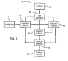
- FIG. 1 there is depicted a diagrammatical representation of a magnetic resonance system 10 and its constituent components.
- An operator 14 employs MR system 10 to perform imaging operations upon patient 18.
- the operator 14 performs these operations via control circuit 22 which controls the operations performed by such constituent components as MR scanner 26, analysis circuit 30, and display circuit 38.
- control circuit 22 which controls the operations performed by such constituent components as MR scanner 26, analysis circuit 30, and display circuit 38.
- Certain utilitarian functions of memory circuit 34 may also be controlled by control circuit 22 but, for purposes of this discussion, the operation of memory circuit 34 will be presumed to be automatic in response to the needs of other component circuits.
- the operator 14 performs the imaging operations on patient 18 by instructing MR scanner 26 to execute a series of radio frequency (RF) pulses according to both automated routines and variables configured at control circuit 22.
- MR scanner 26 collects data derived from these RF pulses which is then passed either directly to an analysis circuit 30 or to a memory circuit 34 which will subsequently provide the data to analysis circuit 30.
- Analysis circuit 30 applies analytical routines on the data in accordance with the parameters set by operator 14 at control circuit 22 to produce image data.
- the image data is in turn passed either to memory circuit 34 for later display or directly to display circuit 38 for immediate display in accordance with instructions received from operator 14 via control circuit 22.
- Display circuit 38 then displays the data on display device 42 for review by the operator or appropriate medical personnel.
- EPI echo planar imaging
- EPI utilizes magnetic gradients along three axes (X, Y, and Z) to provide specific positional data for each proton being imaged.
- Each gradient imparts differential spin information upon each proton being observed.
- the spin information once acquired, allows each proton to be located along each gradient, thus allowing three dimensional positioning of each proton within the derived image.
- gradients are useful in systems, such as MR system 10, for constructing either two dimensional or three dimensional diagnostic images.
- Diffusion imaging allows diagnosticians to examine the diffusion patterns in the tissues of a patient.
- MR diffusion imaging using EPI typically utilizes two large gradient pulses after excitation of the system to perform diffusion weighted imaging.
- the large gradient pulses are designed to impart phase shifts to proton spins which cancel each other out if the spins are stationary, while spins which have moved undergo an observable phase shift. Therefore, in tissues where the fluid is undergoing random or non-directional motion, the phase shifts within an imaging voxel are partially canceled, creating an attenuated image. In tissues where the fluid undergoes directional motion, the phase shifts do not cancel resulting in a complete signal loss in the image. However, in tissue where the fluid is stationary, the phase shifts cancel and an image highlighting differences in diffusion between tissues can be created.
- EPI pulse sequence 60 depicts a spin-echo sequence where the timing of a 90° excitation pulse 68 and a 180° refocusing pulse 72 are shown on a RF axis 64. The spin-echo sequence is used to readout the signal. EPI pulse sequence 60 also depicts an X-gradient axis 76, a Y-gradient axis 80, and a Z-gradient axis 84, each demonstrating the events occurring along those gradients over the same time scale.
- Z-gradient axis 84 is the slice select gradient axis and reflects the slice select pulse 88 as well as a slice select refocus pulse 92.
- X-gradient axis 76 is the frequency encoding gradient axis and depicts the readout 96. The readout occurs at echo time (TE) 74, measured from the time of the excitation pulse 68.
- Diffusion gradient pulses 100 introduce diffusion sensitivity to the EPI sequence.
- Diffusion encoding is performed by modulating the diffusion gradient pulses 100 on X-axis 76, Y-axis 80, and Z-axis 84 for each diffusion measurement. Also depicted are diffusion lobe amplitude 108, commonly denoted g, diffusion lobe width 112, commonly denoted ⁇ , and diffusion lobe interval 116, commonly denoted ⁇ .
- FIG. 3 depicts a dual spin-echo sequence 104 with similar events represented by identical reference numerals.
- dual spin-echo sequence 104 an additional refocusing pulse 72 is added and bipolar diffusion lobes 102 are placed around both refocusing pulses 72.
- the dual spin-echo approach doubles the number of gradient transitions and provides intrinsic refocusing of eddy currents over a fairly wide range of time constants.
- the dual spin-echo approach increases the minimum echo time (TE) 74, however image distortion that would normally arise from eddy currents induced by diffusion gradients is largely removed.
- TE minimum echo time
- Either imaging mode sequence is capable of producing a diffusion weighted image.
- the degree of sensitivity is controlled by a b-value, generally input by operator 14.
- b i,i (2 ⁇ ) 2 g i,j g i,j ( ⁇ 2 ( ⁇ - ⁇ /3)).
- Such a b-matrix describes the diffusion sensitivity from on-axis gradients, the on-diagonal terms, and diffusion sensitivity generated by interactions across gradient axes, the off-diagonal terms or cross-terms.
- the b-matrix values may be determined by integrating waveforms and including imaging gradients. Integration of the products of the k-space trajectory from the 90° excitation pulse 68 to the echo time (TE) 74 on each gradient axis is given by the equation: where the k-space trajectory is given by the equation: where i and j each signify gradient axes, k signifies a detected value, y signifies the gyromagnetic constant, and g signifies the gradient. Equation (2) calculates the k-space trajectory on a gradient axis by integrating the waveform over time. Equation 1 may then be used to integrate the dot-product of the k-space trajectory at each point in time up to TE.
- This integral is the b-value for the gradient waveform at that point in the matrix.
- Off-diagonal values, where i ⁇ j represent the interactions between gradients across the axes.
- One method of compensating for inaccuracies in the b-value involves calculating the actual b-value on each axis (the on-diagonal b-matrix elements) and correcting for deviations from the desired, user configured b-value. After calculating the actual b-value, corrections for the diffusion lobe amplitudes are performed until the on-diagonal b-matrix values are within a given tolerance.
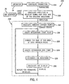
- exemplary stages in the calculation of an actual b-value are illustrated and designated generally by the reference numeral 200.
- the parameters are configured as indicated at step 204.
- This configuration includes setting the prescribed resolution, echo time, field of view, or any other relevant imaging parameters.
- the gradient amplitudes and their respective timing on each axis of the waveform must be calculated, as represented in step 208.
- the image data, from MR scanner 26 and the image parameters, from operator 14 via input step 204 are utilized.
- Corner points are calculated by taking the derivative of the amplitudes along the axes. Those points where slope changes occur are corner points and are kept for further calculation. Non-corner points are discarded.
- a starting point for integration along an axis is determined next in step 216 using the corner point information from step 212.
- the 90° excitation pulse 68 (see Figs. 2 and 3) is located in the pulse sequence. If excitation pulse 68 corresponds to a corner point on the gradient axis, integration begins at that point. If excitation pulse 68 does not correspond to a corner point on the gradient axis, an interpolated point is placed between adjacent corner points and integration begins at the interpolated point.
- each 180° refocusing pulse 72 (see Figs. 2 and 3), if any are present, is then determined in step 220.
- a change in sign of the area occurs since each 180° pulse is basically an inversion. If the refocusing pulse 72 corresponds to a corner point, the change of sign occurs at the corner point. Otherwise an interpolated point is generated between adjacent corner points and the change of sign occurs at the interpolated point.
- An integration end point is then calculated in step 224.
- the end point is calculated by locating TE 74 (see Figs. 2 and 3) and determining if a corner point corresponds to the TE 74. If the TE 74 corresponds to a corner point, integration stops at that corner point. Otherwise an interpolated point is generated between adjacent corner points and integration stops at the interpolated point.
- the gradient waveform along the axis is integrated in step 228. Integration involves determining the k-space trajectory (k i (t)), as given by equation (2), at each corner point using numerical integration of each linear waveform segment.
- the linear waveform segments are defined as the lines connecting adjacent corner points along the gradient axis.
- the result of this integration is a vector of trajectory values, k, at various times, t, along the axis.
- the actual b-value is determined in step 232.
- off-diagonal b-matrix values may also be calculated in step 232 by integrating over the product of two separate k-space trajectory vectors where i ⁇ j , as may be determined in step 228.
- the off-diagonal b-matrix values may provide valuable information regarding pairwise interactions of gradient waveforms across axes.
- the correction process begins at step 254 by scaling the gradient diffusion lobes of an axis using the amplitude and b-value information from the previous steps.
- the scaling process is then repeated for each remaining axis, as needed, until the amplitudes of the diffusion lobes on each gradient axis, X, Y, and Z, have been scaled.
- b-values for each axis are recalculated in step 258 by repeating steps 212 through 232 (as outlined in Fig. 4) using the scaled amplitude values.
- the recalculated b-values are then compared to the prescribed b-value in step 262. If the recalculated b-values (b xx , b yy , and b zz ) are within a given tolerance of the prescribed b-value, no further compensation is performed and the process is ended in step 268. However, if one or more of the recalculated b-values are outside the given tolerance, further fine adjustments are made to the b-value in step 272.
- the fine adjustments to the b-value are accomplished by iteratively adjusting the diffusion lobe amplitude using a numeric search in step 272, as depicted in Fig. 6.
- the numeric search may take the form of a bisection search, as illustrated in Fig. 6, however a variety of numeric searches which allow fine, corrective adjustments to be made may be used as well.
- the minimum and maximum diffusion amplitude points that bracket the desired b-value of an axis are determined.
- the maximum diffusion amplitude point is set to some number greater than the corrected diffusion amplitude determined in step 254 of Fig. 5, such as 110% of the corrected diffusion amplitude.
- the minimum diffusion amplitude point is set to some number less than the corrected diffusion amplitude, such as 90% of the corrected diffusion amplitude. Therefore the corrected diffusion amplitude is an intermediate amplitude bracketed by the maximum and minimum diffusion amplitudes, typically the midpoint. Indeed, in the bisection search described by Fig. 6 the intermediate point is the midpoint diffusion amplitude.
- the calculated b-value based upon this midpoint diffusion amplitude, is checked against the prescribed b-value, in step 284, to determine whether the calculated b-value is within the desired tolerance level. Note that in the first iteration, the calculated b-value is known to be outside the tolerance. For subsequent iterations, however, a b-value is re-calculated, in step 258, and may be within the desire tolerance, thereby ending processing.
- the minimum amplitude is set equal to the midpoint amplitude in step 288.
- the maximum amplitude is set equal to the midpoint amplitude in step 290.
- the revised midpoint amplitude is then used to recalculate the b-value in step 258 (referring back to Fig. 4).
- the revised b-value is then checked against the prescribed b-value at step 284. If the revised b-value is within tolerance, any remaining axes are processed. However if the revised b-value is still outside of the tolerance range, the amplitude midpoint is again iteratively adjusted as per step 284. The process ends at step 268 when the b-value is within tolerance and there are no remaining axes to be processed. While the bisection search depicted in Fig. 6 and described in the preceding text illustrates one embodiment of an acceptable numeric search, those skilled in the art will recognize that other numeric searches may be used to obtain the same type of b-value correction.
- FIG. 7 is a graph showing b-value plotted against time in microseconds before correction where an operator has configured a b-value of 1000. Shaded deviation 300 illustrates the uncorrected error, here approximately 15%.
- Figure 8 demonstrates the same data after calculation and correction of the b-value by the present technique. After scaling of the diffusion lobe amplitudes, b-value error is less than 1% from the prescribed value. Reduction of the b-value error allows for greater operator control in MR diffusion weighted imaging by allowing more precise control of the sensitivity of the device to diffusion processes.
Landscapes
- Physics & Mathematics (AREA)
- Health & Medical Sciences (AREA)
- Nuclear Medicine, Radiotherapy & Molecular Imaging (AREA)
- Vascular Medicine (AREA)
- General Health & Medical Sciences (AREA)
- Radiology & Medical Imaging (AREA)
- Engineering & Computer Science (AREA)
- Signal Processing (AREA)
- High Energy & Nuclear Physics (AREA)
- Condensed Matter Physics & Semiconductors (AREA)
- General Physics & Mathematics (AREA)
- Magnetic Resonance Imaging Apparatus (AREA)
Priority Applications (1)
| Application Number | Priority Date | Filing Date | Title |
|---|---|---|---|
| EP06017132A EP1720029A3 (de) | 2002-09-13 | 2003-09-10 | Berechnung und Korrektur von b-Werten durch Integration linearer Segmente der Gradienten-Pulsform |
Applications Claiming Priority (2)
| Application Number | Priority Date | Filing Date | Title |
|---|---|---|---|
| US243162 | 2002-09-13 | ||
| US10/243,162 US6670812B1 (en) | 2002-09-13 | 2002-09-13 | B-value calculation and correction using a linear segment gradient waveform model |
Related Child Applications (1)
| Application Number | Title | Priority Date | Filing Date |
|---|---|---|---|
| EP06017132A Division EP1720029A3 (de) | 2002-09-13 | 2003-09-10 | Berechnung und Korrektur von b-Werten durch Integration linearer Segmente der Gradienten-Pulsform |
Publications (2)
| Publication Number | Publication Date |
|---|---|
| EP1398643A2 true EP1398643A2 (de) | 2004-03-17 |
| EP1398643A3 EP1398643A3 (de) | 2005-03-23 |
Family
ID=29735576
Family Applications (2)
| Application Number | Title | Priority Date | Filing Date |
|---|---|---|---|
| EP03255640A Ceased EP1398643A3 (de) | 2002-09-13 | 2003-09-10 | Berechnung und Korrektur von b-Werten durch Integration linearer Segmente der Gradienten-Pulsform |
| EP06017132A Withdrawn EP1720029A3 (de) | 2002-09-13 | 2003-09-10 | Berechnung und Korrektur von b-Werten durch Integration linearer Segmente der Gradienten-Pulsform |
Family Applications After (1)
| Application Number | Title | Priority Date | Filing Date |
|---|---|---|---|
| EP06017132A Withdrawn EP1720029A3 (de) | 2002-09-13 | 2003-09-10 | Berechnung und Korrektur von b-Werten durch Integration linearer Segmente der Gradienten-Pulsform |
Country Status (3)
| Country | Link |
|---|---|
| US (1) | US6670812B1 (de) |
| EP (2) | EP1398643A3 (de) |
| JP (1) | JP4660080B2 (de) |
Cited By (1)
| Publication number | Priority date | Publication date | Assignee | Title |
|---|---|---|---|---|
| GB2403549B (en) * | 2003-05-12 | 2006-08-09 | Univ Queensland | Magnetic resonance diffusion imaging with eddy-current compensation |
Families Citing this family (15)
| Publication number | Priority date | Publication date | Assignee | Title |
|---|---|---|---|---|
| US6882876B2 (en) * | 2001-03-27 | 2005-04-19 | Cornell Research Foundation, Inc. | Diagnosis of normal pressure hydrocephalus by automated processing of MR images |
| DE10250922B4 (de) * | 2002-10-31 | 2008-01-31 | Siemens Ag | Verfahren zur Ermittlung des ADC-Koeffizienten in der Diffusionsgewichteten Magnetresonanz-Bildgebung bei Verwendung von Steady-State-Sequenzen |
| DE102005028475B4 (de) * | 2005-06-20 | 2008-04-03 | Siemens Ag | Verfahren und Vorrichtung zur Bestimmung von Koeffizienten eines Diffusionstensors mittels magnetischer Resonanz |
| US7239140B1 (en) * | 2005-12-21 | 2007-07-03 | General Electric Company | Method and apparatus for vibration-related artifact reduction |
| US20100241759A1 (en) * | 2006-07-31 | 2010-09-23 | Smith Donald L | Systems and methods for sar-capable quality of service |
| CN101143093B (zh) * | 2006-09-11 | 2010-09-29 | 西门子(中国)有限公司 | 磁共振扩散成像方法 |
| JP5101896B2 (ja) | 2007-01-17 | 2012-12-19 | ジーイー・メディカル・システムズ・グローバル・テクノロジー・カンパニー・エルエルシー | 画像表示装置、画像表示方法、および、磁気共鳴イメージング装置 |
| US7560926B2 (en) * | 2007-10-15 | 2009-07-14 | Siemens Aktiengesellschaft | b-value optimization for diffusion weighted magnetic resonance imaging |
| US8340376B2 (en) * | 2008-03-12 | 2012-12-25 | Medtronic Navigation, Inc. | Diffusion tensor imaging confidence analysis |
| PL385276A1 (pl) * | 2008-05-26 | 2009-12-07 | Instytut Fizyki Jądrowej Pan Im. Henryka Niewodniczańskiego | Anizotropowy fantom dyfuzji dla kalibracji dowolnej sekwencji obrazowania MR, DTI oraz sposób kalibracji dowolnego tomografu MR |
| DE102008046022A1 (de) * | 2008-09-05 | 2010-03-25 | Siemens Aktiengesellschaft | Phasensensitive Flüssigkeitsunterdrückung |
| CN102008308B (zh) * | 2010-12-29 | 2012-07-04 | 中国科学院深圳先进技术研究院 | 多b值弥散张量成像采样方法 |
| CN110579804B (zh) * | 2019-10-10 | 2020-12-25 | 中国石油化工股份有限公司 | 基于绝对平方梯度的结构张量迹约束下的扩散滤波方法 |
| WO2021096946A1 (en) * | 2019-11-15 | 2021-05-20 | The University Of Chicago | Cancer detection based on four quadrant mapping and matrix analysis of image data |
| US12333714B2 (en) * | 2021-12-09 | 2025-06-17 | Merative Us L.P. | Estimation of b-value in prostate magnetic resonance diffusion weighted images |
Family Cites Families (13)
| Publication number | Priority date | Publication date | Assignee | Title |
|---|---|---|---|---|
| US4591789A (en) | 1983-12-23 | 1986-05-27 | General Electric Company | Method for correcting image distortion due to gradient nonuniformity |
| JPH03109047A (ja) * | 1989-09-22 | 1991-05-09 | Mitsubishi Electric Corp | 磁気共鳴イメージング装置 |
| AU7554894A (en) | 1993-08-06 | 1995-02-28 | Government Of The United States Of America, As Represented By The Secretary Of The Department Of Health And Human Services, The | Method and system for measuring the diffusion tensor and for diffusion tension imaging |
| JPH08229018A (ja) * | 1995-02-28 | 1996-09-10 | Hitachi Ltd | 信号計測における計測点の設定方法 |
| US5671741A (en) * | 1995-08-04 | 1997-09-30 | The Regents Of The University Of California | Magnetic resonance imaging technique for tissue characterization |
| US5864233A (en) * | 1997-02-22 | 1999-01-26 | General Electric Company | Method to reduce eddy current effects in diffusion-weighted echo planar imaging |
| US5969524A (en) * | 1997-04-14 | 1999-10-19 | The United States Of America As Represented By The Department Of Health And Human Services | Method to significantly reduce bias and variance of diffusion anisotrophy measurements |
| DE19834698C2 (de) * | 1997-08-19 | 2001-06-21 | Siemens Ag | Diffusionserfassung mittels magnetischer Resonanz |
| US6163152A (en) | 1998-06-15 | 2000-12-19 | General Electric Company | Method and system for correcting errors in MR images due to regions of gradient non-uniformity for parametric imaging such as quantitative flow analysis |
| US6285187B1 (en) | 1999-04-28 | 2001-09-04 | General Electric Company | Method and apparatus for reducing artifacts in echo planar imaging |
| US6259250B1 (en) | 1999-04-28 | 2001-07-10 | General Electric Company | Method and apparatus for reducing artifacts in echo planar imaging |
| JP2001274670A (ja) * | 2000-03-27 | 2001-10-05 | Toshiba Corp | Lsiの出力回路 |
| WO2002041024A1 (en) * | 2000-11-14 | 2002-05-23 | Koninklijke Philips Electronics N.V. | Magnetic resonance imaging with gradient field non-linearity correction |
-
2002
- 2002-09-13 US US10/243,162 patent/US6670812B1/en not_active Expired - Lifetime
-
2003
- 2003-09-10 EP EP03255640A patent/EP1398643A3/de not_active Ceased
- 2003-09-10 EP EP06017132A patent/EP1720029A3/de not_active Withdrawn
- 2003-09-12 JP JP2003320786A patent/JP4660080B2/ja not_active Expired - Fee Related
Cited By (1)
| Publication number | Priority date | Publication date | Assignee | Title |
|---|---|---|---|---|
| GB2403549B (en) * | 2003-05-12 | 2006-08-09 | Univ Queensland | Magnetic resonance diffusion imaging with eddy-current compensation |
Also Published As
| Publication number | Publication date |
|---|---|
| US6670812B1 (en) | 2003-12-30 |
| JP2004105730A (ja) | 2004-04-08 |
| JP4660080B2 (ja) | 2011-03-30 |
| EP1720029A3 (de) | 2009-06-10 |
| EP1720029A2 (de) | 2006-11-08 |
| EP1398643A3 (de) | 2005-03-23 |
Similar Documents
| Publication | Publication Date | Title |
|---|---|---|
| US6670812B1 (en) | B-value calculation and correction using a linear segment gradient waveform model | |
| US6263228B1 (en) | Method and apparatus for providing separate water-dominant and fat-dominant images from single scan single point dixon MRI sequences | |
| CN104101853B (zh) | 用于确定共振频率偏差的方法和磁共振设备 | |
| EP1391746B1 (de) | Parallele Magnetresonanzbildgebung unter Verwendung von Navigator-Echosignalen | |
| JP6081273B2 (ja) | スライス多重化におけるスライス固有の位相補正 | |
| US8698495B2 (en) | Flip angle imaging with improved B1 mapping for multi-RF transmit systems | |
| US8082127B2 (en) | Method for determining the spatial distribution of magnetic resonance signals through multi-dimensional RF excitation pulses | |
| US9341694B2 (en) | Method and magnetic resonance system for distortion correction in magnetic resonance imaging | |
| EP1845387B1 (de) | Magnetresonanzbildgebungsgerät und Verfahren zur Korrektur statischer Magnetfelder | |
| US7235971B2 (en) | Shimming of MRI scanner involving fat suppression and/or black blood preparation | |
| US5545995A (en) | Measurement of geometric distortion in MRI images | |
| US6472872B1 (en) | Real-time shimming of polarizing field in magnetic resonance system | |
| KR19980064809A (ko) | 와류전류에 의해 유입된 자계를 공간과 시간적으로변화시키기 위한 측정 및 보상방법 | |
| JPH07171122A (ja) | Epi及びgrase mriにおける読み出し傾斜磁界極性の補正方法 | |
| EP3640661B1 (de) | Verfahren und magnetresonanzbildgebungssystem zur aktiven kompensation von wirbelstrominduzierten magnetfeldern in der magnetresonanzbildgebung | |
| EP0965855A2 (de) | Korrektur von Fehlern in Magnetresonanzbildern aufgrund von Gradientenfeldinhomogenitäten | |
| US5572124A (en) | Inspection method and inspection apparatus using nuclear magnetic resonance | |
| US6836113B2 (en) | Measurement and correction of gradient-induced cross-term magnetic fields in an EPI sequence | |
| US11965945B2 (en) | Magnetic resonance system and shimming method and imaging method thereof | |
| US6933720B2 (en) | Sequence preconditioning for ultra-fast magnetic resonance imaging | |
| US5677626A (en) | System for magnetic resonance imaging | |
| EP1004892A1 (de) | Kompensierung eines MRI-Systems für verbleibende Magnetisierung | |
| US20160018500A1 (en) | Magnetic resonance imaging apparatus and magnetic resonance imaging method | |
| US10048339B2 (en) | Method and magnetic resonance scanner for generating a data set | |
| EP1073912A1 (de) | Wiedergewinnung von signalen bei der magnetresonanz-echoplanarbildgebung, die durch feldinhomogenitäten ausgelöscht wurden |
Legal Events
| Date | Code | Title | Description |
|---|---|---|---|
| PUAI | Public reference made under article 153(3) epc to a published international application that has entered the european phase |
Free format text: ORIGINAL CODE: 0009012 |
|
| AK | Designated contracting states |
Kind code of ref document: A2 Designated state(s): AT BE BG CH CY CZ DE DK EE ES FI FR GB GR HU IE IT LI LU MC NL PT RO SE SI SK TR |
|
| AX | Request for extension of the european patent |
Extension state: AL LT LV MK |
|
| PUAL | Search report despatched |
Free format text: ORIGINAL CODE: 0009013 |
|
| AK | Designated contracting states |
Kind code of ref document: A3 Designated state(s): AT BE BG CH CY CZ DE DK EE ES FI FR GB GR HU IE IT LI LU MC NL PT RO SE SI SK TR |
|
| AX | Request for extension of the european patent |
Extension state: AL LT LV MK |
|
| 17P | Request for examination filed |
Effective date: 20050923 |
|
| AKX | Designation fees paid |
Designated state(s): DE NL |
|
| STAA | Information on the status of an ep patent application or granted ep patent |
Free format text: STATUS: THE APPLICATION HAS BEEN REFUSED |
|
| 18R | Application refused |
Effective date: 20060915 |