EP1398565A1 - Générateur de vapeur à construction horizontale - Google Patents
Générateur de vapeur à construction horizontale Download PDFInfo
- Publication number
- EP1398565A1 EP1398565A1 EP02020252A EP02020252A EP1398565A1 EP 1398565 A1 EP1398565 A1 EP 1398565A1 EP 02020252 A EP02020252 A EP 02020252A EP 02020252 A EP02020252 A EP 02020252A EP 1398565 A1 EP1398565 A1 EP 1398565A1
- Authority
- EP
- European Patent Office
- Prior art keywords
- steam generator
- heating surface
- flow
- evaporator
- flow medium
- Prior art date
- Legal status (The legal status is an assumption and is not a legal conclusion. Google has not performed a legal analysis and makes no representation as to the accuracy of the status listed.)
- Withdrawn
Links
Images


Classifications
-
- F—MECHANICAL ENGINEERING; LIGHTING; HEATING; WEAPONS; BLASTING
- F22—STEAM GENERATION
- F22B—METHODS OF STEAM GENERATION; STEAM BOILERS
- F22B1/00—Methods of steam generation characterised by form of heating method
- F22B1/02—Methods of steam generation characterised by form of heating method by exploitation of the heat content of hot heat carriers
- F22B1/18—Methods of steam generation characterised by form of heating method by exploitation of the heat content of hot heat carriers the heat carrier being a hot gas, e.g. waste gas such as exhaust gas of internal-combustion engines
- F22B1/1807—Methods of steam generation characterised by form of heating method by exploitation of the heat content of hot heat carriers the heat carrier being a hot gas, e.g. waste gas such as exhaust gas of internal-combustion engines using the exhaust gases of combustion engines
- F22B1/1815—Methods of steam generation characterised by form of heating method by exploitation of the heat content of hot heat carriers the heat carrier being a hot gas, e.g. waste gas such as exhaust gas of internal-combustion engines using the exhaust gases of combustion engines using the exhaust gases of gas-turbines
Definitions
- the invention relates to a steam generator, in which in a Flowable in an approximately horizontal heating gas direction Heating gas channel arranged an evaporator continuous heating surface which is a number of to flow through a flow medium steam generator pipes connected in parallel, and which is designed so that a compared to another steam generator tube of the same continuous heating surface multi-heated steam generator tube compared to another steam generator tube higher throughput of the flow medium having.
- the In a gas and steam turbine plant, the is relaxed Work equipment or heating gas contained in the gas turbine Heat used to generate steam for the steam turbine.
- the heat transfer takes place in a downstream of the gas turbine Heat recovery steam generator, in which usually a Number of heating surfaces for water preheating, for steam generation and is arranged for steam superheating.
- the heating surfaces are connected to the water-steam cycle of the steam turbine.
- the water-steam cycle usually comprises several z. B. three, pressure levels, each pressure level an evaporator heating surface can have.
- a once-through steam generator is not subject to any pressure limitation, so that for live steam pressures it is far above the critical pressure of water (P kri ⁇ 221 bar) - where it is not possible to distinguish between the phases of water and steam and therefore no phase separation - can be interpreted.
- a high live steam pressure promotes high thermal efficiency and thus low CO 2 emissions from a fossil-fired power plant.
- a continuous steam generator has a simple construction in comparison to a circulation steam generator and can therefore be produced with particularly little effort.
- the use of a steam generator designed according to the continuous flow principle as waste heat steam generator of a gas and steam turbine system is therefore particularly favorable in order to achieve a high overall efficiency of the gas and steam turbine system with a simple construction.
- a heat recovery steam generator in a horizontal design in which the heating medium or heating gas, i.e. the exhaust gas from the gas turbine, in approximately horizontal flow direction the steam generator is guided.
- the steam generator tubes of a heating surface can be constructed horizontally however depending on their positioning a very different one Exposed to heating.
- the output side steam generator tubes connected to a common collector of a once-through steam generator can be a different one Heating of individual steam generator tubes to one Merging steam streams with strong from each other deviating steam parameters and thus to undesirable losses in efficiency, especially to a comparative reduced effectiveness of the affected heating surface and one reduced steam generation.
- a different one Heating of neighboring steam generator tubes can also, especially in the mouth area of collectors Damage to the steam generator pipes or the collector.
- a steam generator is known from EP 0 944 801 B1 is suitable for a layout in horizontal construction and also has the mentioned advantages of a once-through steam generator.
- This is the evaporator heating surface of the known steam generator connected as a continuous heating surface and such designed that a compared to another steam generator tube same continuous heating surface multi-heated steam generator tube one compared to the other steam generator tube has higher throughput of the flow medium.
- Under Pass-through heating surface is generally a heating surface to understand the flow for the flow principle is designed. That of the interconnected as a continuous heating surface Flow medium supplied to evaporator heating surface is in a single pass through this continuous heating surface or by a plurality of series connected Continuous heating surface system completely evaporated.
- the evaporator heating surface connected as a continuous heating surface of the known steam generator thus shows in the type of flow characteristic a natural circulation evaporator heating surface (Natural circulation characteristic) when different occur Heating individual steam generator tubes a self-stabilizing Behavior that requires no outside influence to equalize the outlet temperatures also on differently heated, fluid medium side steam generator pipes connected in parallel.
- the known steam generator has a multi-stage design Evaporator system on which a first continuous heating surface another evaporator continuous heating surface on the flow medium side is connected downstream.
- a reliable and comparatively homogeneous overflow of the flow medium to ensure from the first to the second continuous heating surface is the well-known steam generator with a complex Distribution system provided that a comparatively high structural and constructive effort.
- the invention is therefore based on the object of a steam generator of the type mentioned above, with which also comparatively little structural and constructive effort a particularly high degree of flow stability during operation the evaporator heating surface switched as a continuous heating surface or evaporator continuous heating surface is accessible.
- the invention is based on the consideration that the structural and constructive effort in the creation of the Steam generator can be kept low by the number of the component types used is reduced to a particular degree becomes.
- Such a reduction of components is in the Steam generator of the above type by saving the Continuous heating surface accessible downstream distribution system, by the already provided property of Continuous heating surface, namely the self-stabilizing circulation characteristic, is consistently used.
- This characteristic can namely be the mixture of the different, steam generator tubes connected in parallel to each other flowing fluid and its transfer in the downstream heating surface system without any significant impairment the homogenization achieved in the mixture from a downstream distribution system in the steam generator pipes anyway downstream outlet collector be shifted in without this being noteworthy Flow instabilities or other problems would. Accordingly, this can be comparatively complex Distribution system is eliminated.
- outlet collector can be reached by moving in the direction of the heating gas seen arranged one behind the other and thus one locally different with regard to the heating profile Heating exposed steam generator tubes of the evaporator continuous heating surface on the output side in a common Merging room.
- Such, for those in the heating gas direction seen steam generator pipes arranged one behind the other Common collector room is through an alignment of the outlet collector with its longitudinal axis essentially parallel to the hot gas direction.
- a particularly simple construction of the outlet collector can be reached by this advantageously in is essentially designed as a cylinder body.
- the evaporator system of the steam generator is preferably in the type of a multi-stage design, the Evaporator continuous heating surface in the manner of a pre-evaporator for suitable conditioning of the flow medium its entry into a further evaporator once-through heating surface is provided.
- the further evaporator continuous heating surface therefore serves as a second Evaporator stage to complete the evaporation of the Flow medium.
- the further evaporator once-through heating surface is also expedient taken for a self-stabilizing Flow behavior through consistent use of a natural circulation characteristic designed in the respective steam generator tubes.
- the further evaporator continuous heating surface includes advantageously a number of to flow through the Flow medium steam generator tubes connected in parallel. It is also expediently designed such that one compared to another steam generator tube the other Continuous heating surface of a multi-heated steam generator tube compared to the other steam generator tube higher Has flow rate of the flow medium.
- the further evaporator flow heating surface of the steam generator expediently from essentially vertically oriented for flow through the flow medium from below is formed upward provided steam generator tubes is the further evaporator flow heating surface in a particularly advantageous Design made of U-shaped steam generator tubes educated.
- the further evaporator tubes forming evaporator once-through heating surface each approximately vertically arranged, from Flow medium flowable downward flow and approximately one downstream of this on the flow medium side vertically arranged and upward from the flow medium flowable riser pipe section.
- a such an arrangement enables direct overflow that exits from the first evaporator once-through heating surface Flow medium in the downstream of the fluid medium Steam generator tubes of the further evaporator continuous heating surface.
- Elaborate distribution or connecting lines between the outlet header of the evaporator continuous heating surface and the inlet collector of the further evaporator continuous heating surface as well as assigned mixing and distribution elements can be omitted, and in general the routing is comparatively easy.
- the steam generator is expediently used as a waste heat steam generator a gas and steam turbine plant used.
- the steam generator is advantageously one on the hot gas side Downstream gas turbine.
- This circuit can be used expediently Additional firing to increase the gas turbine the heating gas temperature may be arranged.
- the steam generator shown in FIG. 1 with its evaporator section 1 is one in the manner of a heat recovery steam generator Gas turbine, not shown, connected downstream on the exhaust gas side.
- the steam generator 1 has a surrounding wall 2 which one in an approximately horizontal one, indicated by the arrows 4 Hot gas direction x hot gas duct through which flow 6 forms for the exhaust gas from the gas turbine.
- Hot gas direction x hot gas duct through which flow 6 forms for the exhaust gas from the gas turbine.
- the heating gas duct 6 is a number - in the exemplary embodiment two - from after Flow principle designed evaporator heating surfaces 8, 10 arranged, the for the flow of a flow medium W, D are connected in series.
- That formed from the evaporator continuous heating surfaces 8, 10 multi-stage evaporator system is with undevaporated flow medium W acted upon by a single pass the evaporator flow heating surfaces 8, 10 evaporate and after the exit from the evaporator once-through heating surface 10 as Steam D removed and usually for further overheating Superheater heating surfaces is supplied.
- That from the evaporator continuous heating surfaces 8, 10 formed evaporator system is in the water-steam cycle, not shown Steam turbine switched.
- In addition to this evaporator system are in the water-steam cycle of the steam turbine Number of further heating surfaces, not shown in FIG. 1 which are, for example, superheaters, Medium pressure evaporator, low pressure evaporator and / or can be preheaters.
- the evaporator flow heating surface 8 is by a number of connected in parallel to the flow through the flow medium W.
- Steam generator tubes 12 formed.
- the steam generator pipes 12 are essentially with their longitudinal axis aligned vertically and for a flow of the flow medium W from a lower entry area to one upper outlet area, i.e. from bottom to top.
- the evaporator continuous heating surface 8 is designed such that they are used for feeding the steam generator tubes 12 comparatively low mass flow density is suitable, wherein the design flow conditions in the steam generator tubes 12 have a natural circulation characteristic.
- This natural circulation characteristic shows a comparison to a further steam generator tube 12 of the same evaporator continuous heating surface 8 more heated steam generator tube 12 one compared to the other steam generator tube 12 higher Throughput of the flow medium W on.
- the continuous heating surface 8 Additional evaporator continuous heating surface downstream of the flow medium 10 designed.
- the further evaporator continuous heating surface 10 of the steam generator 1 comprises a plurality of to in the manner of a tube bundle Flow through the flow medium W connected in parallel Steam generator tubes 22.
- the so arranged side by side steam generator tubes 22 An assigned distributor on the flow medium side or entry collector 24 upstream and a common exit collector 26 downstream.
- each steam generator tube forming the further evaporator continuous heating surface 10 22 an approximately vertically arranged Downflow piece through which the flow medium W flows in the downward direction 32.
- each steam generator tube includes 22 a downstream of the downpipe piece 32 on the flow medium side, approximately vertically arranged and from the flow medium W riser pipe through which flow flows in the upward direction 34th
- the riser pipe piece 34 is associated with it Downpipe piece 32 connected via an overflow piece 36.
- the overflow pieces 36 are within the embodiment Heating gas channel 6 out.
- Each steam generator tube 22 of the further evaporator once-through heating surface 10 has, as can be seen in FIG almost U-shaped shape, with the legs of the U through the Downpipe piece 32 and the riser piece 34 and the connecting elbow are formed by the overflow piece 36.
- a steam generator tube 22 generates the geodetic pressure contribution of the flow medium W in the area of the downpipe section 32 - in contrast to the area of the riser pipe section 34 - a flow promoting and not one flow-reducing pressure contribution.
- the im Downpipe piece 32 located water column on undevaporated Flow medium W "pushes" the flow through each Steam generator tube 22 with, instead of hindering them.
- the steam generator tube 22 has one overall comparatively low pressure loss.
- each steam generator tube is 22 each in the entry area of his downpipe section 32 and in the outlet area of its riser pipe 34 in the kind of a suspended construction on the ceiling of the heating gas duct 6 hung or fastened.
- the lower ends spatially of the respective downpipe piece 32 and the respective riser pipe piece 34, through their overflow piece 36 with each other connected, however, are not directly spatially on Heating gas channel 6 fixed. Elongations of these segments of the Steam generator tubes 22 can thus be tolerated without risk of damage, the respective overflow piece 36 as an expansion curve acts.
- This arrangement of the steam generator tubes 22 is thus mechanically particularly flexible and with regard to thermal Stresses insensitive to differential expansion.
- the steam generator 1 is for reliable, homogeneous flow control with a comparatively simple design designed.
- This is designed for the evaporator continuous heating surface 8 envisaged natural circulation characteristics consistently used to simplify the distribution system.
- This natural circulation characteristic and the associated designed to be designed to be comparatively low Mass flow density enables merging of the partial flows from one another seen in the heating gas direction x arranged and thus heated differently Steam generator pipes in a common room. Saving of an independent, complex distribution system thus a shift in the mixing of the evaporator flow heating surface 8 outflowing flow medium W in the outlet collector (s) 20 possible.
- the steam generator 1 With the steam generator 1 in a horizontal construction and using the further evaporator once-through heating surface 10 with Steam generator tubes 22 which are essentially U-shaped can 22 steam bubbles in the downpipe section 32 of a steam generator tube occur. These vapor bubbles could go against the Flow direction of the flow medium W in the respective downpipe section 32 rise and thus the stability of the flow and also hinder the reliable operation of the steam generator 1. To reliably prevent this, the steam generator is 1 for feeding the further evaporator continuous heating surface 10 with already partially evaporated flow medium W designed.
- the flow medium W is fed into the further one Evaporator continuous heating surface 10 is provided in such a way that the flow medium W in the downpipe piece 32 of the respective Steam generator tube 22 a flow rate of more has a predetermined minimum speed.
- This is in turn dimensioned such that on the basis of the sufficient high flow velocity of the flow medium W in each Downpipe piece 32 possibly existing there Steam bubbles reliably in the direction of flow of the flow medium W entrained and over the respective overflow piece 36 transferred into the downstream pipe section 34 become.
- the further evaporator continuous heating surface 10 of the steam generator 1 is the further evaporator continuous heating surface 10 of the steam generator 1 on the flow medium side in the manner of a Pre-evaporator upstream of the evaporator heating surface 8.
- the one provided in the manner of a pre-evaporator Evaporator continuous heating surface 8 is comparatively spatial colder area of the heating gas duct 6 and thus on the hot gas side downstream to the further evaporator continuous heating surface 10 arranged.
- the further evaporator continuous heating surface 10, however, is near the entrance area of the heating gas channel 6 for the flowing out of the gas turbine Heating gas arranged and therefore a comparative in the operating case exposed to strong heat input from the heating gas.
- the evaporator flow heating surface 8 is dimensioned in such a way that, in the event of operation, the further downstream Evaporator flow heating surface 10 flowing fluid W is a flow velocity of more than that Take along of the resulting 32 pieces in the downpipe or existing vapor bubbles required minimum speed having.
- the design is aimed at high operational security achievable to a particular degree, by the mean heat absorption during operation in Essentially uniform on the evaporator continuous heating surface 8 and on the further evaporator continuous heating surface 10 is distributed.
- Under Consideration of the mass flows occurring for the evaporator flow heating surface 8 one in view to the number of steam generator tubes 22 on the flow medium side downstream further evaporator continuous heating surface 10 suitably chosen number of steam generator tubes 12 on.
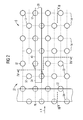
- each two adjacent Pipe layers 14 in a direction perpendicular to the heating gas direction x seen offset from each other, so that regarding the arrangement of the steam generator tubes 12 a substantially diamond-shaped basic pattern results.
- the outlet collectors 20 of which in FIG. 2 only one is shown, positioned so that in each Outlet collector 20 from each tube layer 14 Steam generator tube 12 opens. It is also recognizable that each exit header 20 with an associated entrance header 24 for the evaporator continuous heating surface 8 downstream further evaporator continuous heating surface 10 a structural unit 40 is integrated.
- FIG. 2 also shows that the further evaporator continuous heating surface 10 forming steam generator tubes 22 also seen a number of x in the heating gas direction Form pipe layers one behind the other, the in the direction of the heating gas x seen first two pipe layers from the riser pipe pieces 34 of the steam generator tubes 22 are formed, the on the output side into the outlet collector 26 for the vaporized Flow medium D open.
- the seen in the heating gas direction x The next two pipe layers, however, are from the downpipe pieces 32 of the steam generator tubes 22 formed, the input side connected to an associated entry collector 24 are.
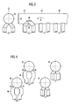
- Figure 3 shows a side view of sections of the mouth region the steam generator tubes 12, 22 into the respectively assigned structural unit 40, on the one hand, the outlet collector 20 for a number of the evaporator continuous heating surface 8 forming steam generator tubes 12 and on the other hand the inlet header 24 for two each of the further evaporator continuous heating surface 10 forming steam generator tubes 22 includes. It is particularly clear from this illustration that flowing out of the steam generator tubes 12 into the outlet header 20 entering flow medium W on direct Path in the assigned to the further evaporator once-through heating surface 10 Entry collector 24 can overflow. When overflowing of the flow medium W bounces depending on the operating state first against a bottom plate 42 of the entry collector 24 comprehensive structural unit 40. As a result this impact creates a vortex and particularly intimate Mixing of the flow medium W before it from Inlet collector 24 from in the downpipe pieces 32 of the associated Steam generator tubes 22 passes.
- the inlet manifold 24 for the steam generator tubes 22 designed end part of the structural Unit 40 designed such that the outflow of the flow medium W into the steam generator tubes 22 for everyone Steam generator tubes 22 vertically from a single plane to the cylinder axis of the structural unit 40 out.
- each overflow piece 46 is assigned to each steam generator tube 22.
- Each overflow piece 46 runs obliquely to Heating gas direction x and connects the upper area of each assigned steam generator tube 22 with the respective Outlet opening 48 of the inlet collector 24.
- FIG. 4 To further clarify the pipe guides in the area of their Entries into and out of the building unit 40 in FIG. 4 is a number of such structural units 40 shown in front view, the one designated by IV in FIG Cutting line is used. It can be seen that the two structural elements shown on the left in FIG Units 40, which in the area of their entry collector 24 trained for the downstream steam generator tubes 22 Are shown at the end, each over the overflow pieces 46 the downstream downpipe pieces 32 of the steam generator tubes 22 are connected.
- the steam generator 1 according to Figure 1 and with the special configurations according to Figures 2 to 4 is special for one safe operation of the further evaporator continuous heating surface 10 designed.
- the steam generator 1 when operating the steam generator 1 ensures that the substantially u-shaped Evaporator continuous heating surface 10 with flow medium W with a flow rate of more than a given one Minimum speed is applied. Thereby is achieved that in the downpipe pieces 32 the other Evaporator flow heating surface 10 forming steam generator tubes 22 existing vapor bubbles entrained and in each downstream riser pipe 34 are spent.
- the feed takes place further evaporator continuous heating surface 10 using the this upstream evaporator continuous heating surface 8 in such a way that in the further evaporator continuous heating surface 10 inflowing flow medium W a vapor content or a Enthalpy of more than a specifiable minimum vapor content or has more than a predetermined minimum enthalpy.
- the Evaporator flow heating surfaces 8, 10 designed or dimensioned that the steam content in all operating points or the enthalpy of the flow medium D, W when entering the further evaporator flow heating surface 10 above suitable predetermined characteristics, as exemplified in Figures 5a, 5b are shown.
- the further continuous heating surface 10, which is designed to comply with these conditions, is dimensioned, i.e., for example, with regard to the type, number and design of the steam generator tubes 30 which form it, taking into account the heat available within the heating gas duct 6, which is designed for its spatial positioning, to these boundary conditions customized.
Priority Applications (9)
| Application Number | Priority Date | Filing Date | Title |
|---|---|---|---|
| EP02020252A EP1398565A1 (fr) | 2002-09-10 | 2002-09-10 | Générateur de vapeur à construction horizontale |
| TW092122086A TW200404136A (en) | 2002-09-10 | 2003-08-12 | Steam-generator in horizontally situated construction |
| AU2003264124A AU2003264124A1 (en) | 2002-09-10 | 2003-08-28 | Horizontally assembled steam generator |
| EP03794968A EP1537358B1 (fr) | 2002-09-10 | 2003-08-28 | Generateur de vapeur construit horizontalement |
| PCT/EP2003/009571 WO2004025177A1 (fr) | 2002-09-10 | 2003-08-28 | Generateur de vapeur construit horizontalement |
| CA2498216A CA2498216C (fr) | 2002-09-10 | 2003-08-28 | Generateur de vapeur construit horizontalement |
| JP2004535206A JP4628788B2 (ja) | 2002-09-10 | 2003-08-28 | 廃熱ボイラ |
| US10/527,279 US7428374B2 (en) | 2002-09-10 | 2003-08-28 | Horizontally assembled steam generator |
| CN03821488.1A CN1682075B (zh) | 2002-09-10 | 2003-08-28 | 卧式蒸汽发生器 |
Applications Claiming Priority (1)
| Application Number | Priority Date | Filing Date | Title |
|---|---|---|---|
| EP02020252A EP1398565A1 (fr) | 2002-09-10 | 2002-09-10 | Générateur de vapeur à construction horizontale |
Publications (1)
| Publication Number | Publication Date |
|---|---|
| EP1398565A1 true EP1398565A1 (fr) | 2004-03-17 |
Family
ID=31725380
Family Applications (2)
| Application Number | Title | Priority Date | Filing Date |
|---|---|---|---|
| EP02020252A Withdrawn EP1398565A1 (fr) | 2002-09-10 | 2002-09-10 | Générateur de vapeur à construction horizontale |
| EP03794968A Expired - Fee Related EP1537358B1 (fr) | 2002-09-10 | 2003-08-28 | Generateur de vapeur construit horizontalement |
Family Applications After (1)
| Application Number | Title | Priority Date | Filing Date |
|---|---|---|---|
| EP03794968A Expired - Fee Related EP1537358B1 (fr) | 2002-09-10 | 2003-08-28 | Generateur de vapeur construit horizontalement |
Country Status (8)
| Country | Link |
|---|---|
| US (1) | US7428374B2 (fr) |
| EP (2) | EP1398565A1 (fr) |
| JP (1) | JP4628788B2 (fr) |
| CN (1) | CN1682075B (fr) |
| AU (1) | AU2003264124A1 (fr) |
| CA (1) | CA2498216C (fr) |
| TW (1) | TW200404136A (fr) |
| WO (1) | WO2004025177A1 (fr) |
Families Citing this family (7)
| Publication number | Priority date | Publication date | Assignee | Title |
|---|---|---|---|---|
| EP1701090A1 (fr) * | 2005-02-16 | 2006-09-13 | Siemens Aktiengesellschaft | Générateur de vapeur à construction horizontale |
| EP2065641A3 (fr) * | 2007-11-28 | 2010-06-09 | Siemens Aktiengesellschaft | Procédé de fonctionnement d'un générateur de vapeur en flux continu, ainsi que générateur de vapeur en flux à sens unique |
| US9428702B2 (en) * | 2011-07-12 | 2016-08-30 | Gas Technology Institute | Agglomerator with ceramic matrix composite obstacles |
| WO2013108216A2 (fr) | 2012-01-17 | 2013-07-25 | Alstom Technology Ltd | Dispositifs de commande d'écoulement et procédés pour évaporateur horizontal à passage unique |
| US9989320B2 (en) | 2012-01-17 | 2018-06-05 | General Electric Technology Gmbh | Tube and baffle arrangement in a once-through horizontal evaporator |
| DE102014206043B4 (de) * | 2014-03-31 | 2021-08-12 | Mtu Friedrichshafen Gmbh | Verfahren zum Betreiben eines Systems für einen thermodynamischen Kreisprozess mit einem mehrflutigen Verdampfer, Steuereinrichtung für ein System, System für einen thermodynamischen Kreisprozess mit einem mehrflutigen Verdampfer, und Anordnung einer Brennkraftmaschine und eines Systems |
| EP4012315A4 (fr) * | 2019-08-06 | 2022-08-03 | Mitsubishi Electric Corporation | Échangeur de chaleur et appareil à cycle de réfrigération |
Citations (5)
| Publication number | Priority date | Publication date | Assignee | Title |
|---|---|---|---|---|
| US3442324A (en) * | 1967-03-06 | 1969-05-06 | American Mach & Foundry | Heat recovery device for turbine gases |
| US4188916A (en) * | 1978-05-15 | 1980-02-19 | Deltak Corporation | Waste heat boiler for abstraction of heat energy from gaseous effluent containing corrosive chemical contaminants |
| DE3441972A1 (de) * | 1984-11-16 | 1986-05-28 | Belgorodskij zavod energetičeskogo mašinostroenija imeni 60-letija Sojuza SSR, Belgorod | Kessel |
| EP0450072A1 (fr) * | 1988-12-22 | 1991-10-09 | Miura Co., Ltd. | Chaudiere carree a conduites multiples et a passage unique |
| US5353749A (en) * | 1993-10-04 | 1994-10-11 | Zurn Industries, Inc. | Boiler design |
Family Cites Families (5)
| Publication number | Priority date | Publication date | Assignee | Title |
|---|---|---|---|---|
| US601970A (en) | 1898-04-05 | Ors of part to charley ellison | ||
| CA1254458A (fr) * | 1984-11-26 | 1989-05-23 | Proizvodstvennoe Obiedinenie Po Proektirovaniju, Naladke, Modernizatsii I Remontu Energeticheskogo Oborudovania "Tsentroenergotsvetmet" | Chaudiere |
| CN2124375U (zh) * | 1992-02-03 | 1992-12-09 | 河北工学院 | 造气上、下行煤气废热集中回收器 |
| DE19651678A1 (de) | 1996-12-12 | 1998-06-25 | Siemens Ag | Dampferzeuger |
| US6019070A (en) * | 1998-12-03 | 2000-02-01 | Duffy; Thomas E. | Circuit assembly for once-through steam generators |
-
2002
- 2002-09-10 EP EP02020252A patent/EP1398565A1/fr not_active Withdrawn
-
2003
- 2003-08-12 TW TW092122086A patent/TW200404136A/zh unknown
- 2003-08-28 WO PCT/EP2003/009571 patent/WO2004025177A1/fr active Application Filing
- 2003-08-28 JP JP2004535206A patent/JP4628788B2/ja not_active Expired - Fee Related
- 2003-08-28 CA CA2498216A patent/CA2498216C/fr not_active Expired - Fee Related
- 2003-08-28 AU AU2003264124A patent/AU2003264124A1/en not_active Abandoned
- 2003-08-28 US US10/527,279 patent/US7428374B2/en not_active Expired - Fee Related
- 2003-08-28 CN CN03821488.1A patent/CN1682075B/zh not_active Expired - Fee Related
- 2003-08-28 EP EP03794968A patent/EP1537358B1/fr not_active Expired - Fee Related
Patent Citations (5)
| Publication number | Priority date | Publication date | Assignee | Title |
|---|---|---|---|---|
| US3442324A (en) * | 1967-03-06 | 1969-05-06 | American Mach & Foundry | Heat recovery device for turbine gases |
| US4188916A (en) * | 1978-05-15 | 1980-02-19 | Deltak Corporation | Waste heat boiler for abstraction of heat energy from gaseous effluent containing corrosive chemical contaminants |
| DE3441972A1 (de) * | 1984-11-16 | 1986-05-28 | Belgorodskij zavod energetičeskogo mašinostroenija imeni 60-letija Sojuza SSR, Belgorod | Kessel |
| EP0450072A1 (fr) * | 1988-12-22 | 1991-10-09 | Miura Co., Ltd. | Chaudiere carree a conduites multiples et a passage unique |
| US5353749A (en) * | 1993-10-04 | 1994-10-11 | Zurn Industries, Inc. | Boiler design |
Also Published As
| Publication number | Publication date |
|---|---|
| EP1537358A1 (fr) | 2005-06-08 |
| AU2003264124A1 (en) | 2004-04-30 |
| JP4628788B2 (ja) | 2011-02-09 |
| US7428374B2 (en) | 2008-09-23 |
| CN1682075A (zh) | 2005-10-12 |
| WO2004025177A1 (fr) | 2004-03-25 |
| CN1682075B (zh) | 2012-09-05 |
| CA2498216C (fr) | 2011-11-15 |
| US20050257753A1 (en) | 2005-11-24 |
| CA2498216A1 (fr) | 2004-03-25 |
| EP1537358B1 (fr) | 2012-11-28 |
| JP2005538337A (ja) | 2005-12-15 |
| TW200404136A (en) | 2004-03-16 |
Similar Documents
| Publication | Publication Date | Title |
|---|---|---|
| EP0944801B1 (fr) | Chaudiere a vapeur | |
| EP1848925B1 (fr) | Générateur de vapeur de type horizontal | |
| EP0993581B1 (fr) | Generateur de vapeur par recuperation de chaleur perdue | |
| DE10127830B4 (de) | Dampferzeuger | |
| DE102009036064B4 (de) | rfahren zum Betreiben eines mit einer Dampftemperatur von über 650°C operierenden Zwangdurchlaufdampferzeugers sowie Zwangdurchlaufdampferzeuger | |
| EP0591163B1 (fr) | Installation combinee a turbines a gaz et a vapeur | |
| EP1588095B1 (fr) | Generateur de vapeur | |
| EP1512907A1 (fr) | Procédé pour le demarrage d'un générateur de vapeur à passage unique et le générateur de vapeur à passage unique pour la mise en oeuvre du procédé | |
| EP2324285B1 (fr) | Générateur de vapeur à récupération de chaleur | |
| EP1710498A1 (fr) | Générateur de vapeur | |
| EP1794495B1 (fr) | Generateur de vapeur en continu chauffe a l'aide d'un combustible fossile | |
| EP1701091A1 (fr) | Générateur de vapeur à passage unique | |
| EP2321578B1 (fr) | Générateur de vapeur en continu | |
| EP1262638A1 (fr) | Dispositif pour refroidir le fluide de refroidissement d'une turbine à gaz et installation à turbine à gaz et à vapeur avec un tel dispositif | |
| EP0006163B1 (fr) | Procédé et dispositifs pour diriger les gaz de combustion dans une chaudière | |
| EP1660812B1 (fr) | Générateur de vapeur à passage unique et méthode pour faire fonctionner ledit générateur de vapeur à passage unique | |
| EP1537358B1 (fr) | Generateur de vapeur construit horizontalement | |
| EP1398564A1 (fr) | Procédé pour faire fonctionner un générateur de vapeur à construcion horizontale, et générateur de vapeur pour mettre en oeuvre ledit procédé | |
| EP0498257B1 (fr) | Procédé et dispositif pour le chauffage d'un four rotatif de carbonisation | |
| EP1512906A1 (fr) | Générateur de vapeur de construction horizontale à passage unique et méthode pour faire fonctionner ledit générateur de vapeur à passage unique | |
| DE2826048C3 (de) | Anordnung zur Rauchgasführung und Rauchgasentnahme bei einem Wärmekessel | |
| EP2564117B1 (fr) | Générateur de vapeur |
Legal Events
| Date | Code | Title | Description |
|---|---|---|---|
| PUAI | Public reference made under article 153(3) epc to a published international application that has entered the european phase |
Free format text: ORIGINAL CODE: 0009012 |
|
| AK | Designated contracting states |
Kind code of ref document: A1 Designated state(s): AT BE BG CH CY CZ DE DK EE ES FI FR GB GR IE IT LI LU MC NL PT SE SK TR |
|
| AX | Request for extension of the european patent |
Extension state: AL LT LV MK RO SI |
|
| AKX | Designation fees paid | ||
| REG | Reference to a national code |
Ref country code: DE Ref legal event code: 8566 |
|
| STAA | Information on the status of an ep patent application or granted ep patent |
Free format text: STATUS: THE APPLICATION IS DEEMED TO BE WITHDRAWN |
|
| 18D | Application deemed to be withdrawn |
Effective date: 20040918 |