EP1398232A1 - Anordnung eines Motors an einer Stützwinde - Google Patents
Anordnung eines Motors an einer Stützwinde Download PDFInfo
- Publication number
- EP1398232A1 EP1398232A1 EP03019580A EP03019580A EP1398232A1 EP 1398232 A1 EP1398232 A1 EP 1398232A1 EP 03019580 A EP03019580 A EP 03019580A EP 03019580 A EP03019580 A EP 03019580A EP 1398232 A1 EP1398232 A1 EP 1398232A1
- Authority
- EP
- European Patent Office
- Prior art keywords
- arrangement according
- motor
- drive
- connecting shaft
- spring
- Prior art date
- Legal status (The legal status is an assumption and is not a legal conclusion. Google has not performed a legal analysis and makes no representation as to the accuracy of the status listed.)
- Granted
Links
- 230000035939 shock Effects 0.000 claims description 10
- 239000006096 absorbing agent Substances 0.000 claims description 6
- 239000013013 elastic material Substances 0.000 claims description 3
- 230000000295 complement effect Effects 0.000 claims description 2
- 230000005540 biological transmission Effects 0.000 description 7
- 230000002349 favourable effect Effects 0.000 description 3
- 238000004026 adhesive bonding Methods 0.000 description 2
- 230000000694 effects Effects 0.000 description 2
- 239000000463 material Substances 0.000 description 2
- 238000005192 partition Methods 0.000 description 2
- 238000013016 damping Methods 0.000 description 1
- 238000006073 displacement reaction Methods 0.000 description 1
- 238000005553 drilling Methods 0.000 description 1
- 230000003993 interaction Effects 0.000 description 1
- 238000012423 maintenance Methods 0.000 description 1
- 230000007257 malfunction Effects 0.000 description 1
- 230000002093 peripheral effect Effects 0.000 description 1
- 238000009420 retrofitting Methods 0.000 description 1
- 238000004073 vulcanization Methods 0.000 description 1
Images


Classifications
-
- B—PERFORMING OPERATIONS; TRANSPORTING
- B60—VEHICLES IN GENERAL
- B60S—SERVICING, CLEANING, REPAIRING, SUPPORTING, LIFTING, OR MANOEUVRING OF VEHICLES, NOT OTHERWISE PROVIDED FOR
- B60S9/00—Ground-engaging vehicle fittings for supporting, lifting, or manoeuvring the vehicle, wholly or in part, e.g. built-in jacks
- B60S9/02—Ground-engaging vehicle fittings for supporting, lifting, or manoeuvring the vehicle, wholly or in part, e.g. built-in jacks for only lifting or supporting
- B60S9/04—Ground-engaging vehicle fittings for supporting, lifting, or manoeuvring the vehicle, wholly or in part, e.g. built-in jacks for only lifting or supporting mechanically
- B60S9/06—Ground-engaging vehicle fittings for supporting, lifting, or manoeuvring the vehicle, wholly or in part, e.g. built-in jacks for only lifting or supporting mechanically of screw-and-nut type
- B60S9/08—Ground-engaging vehicle fittings for supporting, lifting, or manoeuvring the vehicle, wholly or in part, e.g. built-in jacks for only lifting or supporting mechanically of screw-and-nut type the screw axis being substantially vertical
Definitions
- the invention relates to an arrangement of a motor in pairs Mounted landing gear, especially on a semitrailer of a Tractor, with the landing gear over a connecting shaft interconnected and by putting the motor into operation are telescopic.
- the landing gear After the up and down of the trailer, the landing gear becomes telescoped, that is retracted or extended, and support the from standing semitrailers.
- the extension and retraction is usually via a hand crank attached to one of the landing gear winches from Driver made. To the driver of this physically to relieve strenuous work, there are aspirations that Driving force for extending and retracting the landing gear by a Apply engine.
- the invention was the object of an arrangement to provide a motor that minimizes damage to the engine and at the same time is inexpensive to produce.
- the object is achieved with an arrangement in which the motor engages with its drive shaft on the connecting shaft and is supported on a relative to the engine stationary component.
- Another advantage of the inventive arrangement results from the fact that the engine in a protected area between the landing gear, at Semi-trailers below the trailer floor, is attached and thereby can hardly be damaged during driving.
- the spring element prevents damage to the engine when the Landing gear drives against its upper or lower stop while the engine, due to its inertia, still trailing.
- By the elasticity of the spring element becomes a shock load, especially when driving against the upper hard stop but also kept away from the engine when starting. This increases the Life of the engine and also leaves the use cheaper engines too.
- the spring element comprises a spiral spring, in particular a helical spring, a torsion element or a Shock absorber, wherein the coil spring both in its axial extent can be installed or can also be used as a torsion element.
- Shock absorbers are also called spring damper packages Understood.
- torsion element is also an elastic hose or a elastic pipe piece in question.
- the stationary component is at least one of two landing legs and here particularly preferred the back of the Landing gear counter-plate on which the landing gear with the semi-trailer is screwed.
- the coil spring or the torsion element is rotationally fixed attached to at least one of the landing gear and the engine so that when driving the landing gear against a stop the entire engine gently intercepted in its direction of rotation.
- the coil spring or the torsion element surrounds the Connecting shaft at least partially.
- the stationary component is the Bottom of a trailer floor.
- the Coil spring or the shock absorber between the engine and the Be arranged underside of the trailer floor are the Coil spring or the shock absorber between the engine and the Be arranged underside of the trailer floor.
- the coil spring has an upper and a lower one on a guide tube and arranged respectively an end stop at its outer end fixable part spring includes, being on the guide tube between the top and lower part spring a mounting sleeve is arranged.
- a mounting sleeve is arranged.
- the upper Compress part spring creating a shock load of the engine and downstream in the power flow components is avoided. With a fully extended landing gear touched the support leg of the landing gear supports the ground, i.
- the landing gear has its own reached bottom stop.
- the engine rotates for a short time due to its inertia, so that again the Mounting sleeve presses against the upper part spring and thereby conditionally a shock load is avoided.
- the landing gear becomes, as the engine changes its sense of rotation, Accordingly, both when starting and when driving against the upper stop compresses the lower part spring.
- the guide tube is pushed onto an inner tube and with this in the axial direction in different positions connectable. This is a setting and adjustment of the Guide tube to the spatial conditions of the concrete Use case possible, so that an optimized interaction the clamped by the part springs mounting sleeve with the im Attachment point attached engine is guaranteed.
- the Connecting shaft rotatably secured to the drive shaft. This is a lossless and maintenance-free power transmission realizable.
- the elastic sleeve is off made of an elastic material, such. Gum.
- the elastic sleeve is designed as an air chamber sleeve.
- the air chamber sleeve comprises one of the outer wall of the Connecting shaft adapted inner circumferential wall and a adapted to the inner wall of the drive shaft external Peripheral wall, with the inside and the outside Circumferential wall over radially extending spaced apart Partitions are interconnected. Between the partitions Air chambers are formed.
- the fixed component at least one of the landing gear, a Trailer floor or a vehicle carrier, where the stationary Component is rigidly connected to the engine.
- the elastic sleeve is rotationally fixed to the connecting shaft and the drive shaft attached. This can, for example, by Gluing or vulcanization done.
- the belt drive comprises a Drive belt, which rotatably arranged on the drive shaft Drive wheel and a rotatably mounted on the connecting shaft Worm wheel wraps around.
- the drive belt made of an elastic material be.
- the Slip clutch with an internal toothing on the drive shaft arranged drive gear on which a complementary with a External teeth arranged on the connecting shaft Output gear meshes with the drive gear and / or the Output gear frictionally with a predetermined friction on the Drive shaft or output shaft is fixed.
- a jerky Load slips now at least one of the gears in Circumferential direction on its shaft, thereby preventing one Transmission of the shock in the engine.
- the drive shaft as a hollow shaft train. This results in the advantage that the usual Used connecting shaft through the trained as a hollow shaft Drive shaft inserted therethrough and conditionally continue to use can be.
- the hollow shaft may have a circular cross-section. This in turn simplifies the engine-side power transmission to the Drive shaft.
- the engine is not self-locking, i. the landing gear
- the landing gear For example, in case of power failure or other malfunction of the Motors are moved as before by means of a hand crank.
- the engine comprises an electric motor. This is cost-effective, low maintenance, compact and easy to use a power cable independent of a compressed air supply to join.
- the engine is for a torque of 5 to 15 Nm designed.
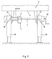
- FIG. 1 shows pairs arranged on a semi-trailer 3 Landing winds 2a, 2b, which in their extended state the ground touch.
- a hand crank 29 can be seen on the support winch 2a, with which in case of failure of the engine 1, the landing gear 2a, 2b can be moved.
- the landing gear 2a, 2b are over a Support winch counter plate 31 screwed to the trailer 3.
- Supporting winches 2a, 2b are each arranged a landing gear transmission.
- the engine 1 is on the two landing gears 2a, 2b, with each other connecting connecting shaft 4 arranged and encloses with its drive shaft 5, the connecting shaft 4 rotatably.
- the motor 1 is elastic with the support winch 2b connected and simultaneously secured against turning.
- the Torsionselement can also be used as elastic hose 10 or be executed elastic tube.
- the motor 1 instead of a torsion element 8 with a coil spring 7 elastically connected to the support winch 2b. there extends centrally through the coil spring 7, the connecting shaft. 4
- FIG. 3 shows in perspective an alternative embodiment the engine 1 with a spring element 6 at the bottom of a Semi-trailer floor 11 (see Figure 1) is supported.
- the guide tube 9 in the axial direction of the 19th slidably mounted.
- the adjusting bolts 35th pulled out, the guide tube 9 and the part springs 14, 15 and the fastening sleeve 16 with respect to the mounting plate 32nd fastened to the underside of the trailer (not shown)
- Inner tube 18 is moved and the adjusting bolt 35 in the desired Position, for example, in one of the visible subordinate Positions 20a, 20b, 20c, inserted.
- the position can be of the engine 1 to a predetermined position of the connecting shaft 4 adjust without the spring element 6 in its elastic Properties changed.
- the spring element 6 and the motor 1 in one Rear view shown, wherein the upper and lower part spring 14, 15th are covered by the engine 1.
- the spring element 6 is by means of a Screw 33 connected to the mounting plate 32.
- Figure 5 shows a section through the engine 1, wherein between the Drive shaft 5 and the connecting shaft 4, a spring element 6 in Form of an elastic sleeve 21 is arranged.
- the elastic sleeve 21 is one side led out of the engine 1 and has a through the Elastic sleeve 21 and the connecting shaft 4 extending bore 36th on, through which a connecting bolt 34 is inserted.
- the Connecting bolts 34 are both the elastic sleeve 21 and the Connecting shaft 4 positively and thus against rotation with each other connected.
- the drive shaft 5 is cohesively, for example by Gluing, also connected to the elastic sleeve 21.
- the engine 1 can be rigid be attached to the underside of the trailer floor 11, as the Elasticity in case of driving the landing gear 2a, 2b, against a Stop between the drive shaft 4 and connecting shaft 4 takes place.
- FIG. 6 shows an air chamber sleeve 24 as a special form of Elastic sleeve 21. Above are examples of the air chambers 24a in a relaxed state while the air chambers 24b are shown under load. Inserted is the air chamber sleeve 24 rotationally fixed between the drive shaft 5 and the connecting shaft. 4
- FIG. 7 An alternative spring element 6 is shown in FIG. 7 as a belt drive 22 shown.
- a drive wheel 26 drives a drive wheel 26 via a drive belt 25th a driven gear 27, wherein the drive wheel 26 rotatably with the Drive shaft 5 and the output gear 27 rotatably with the Connecting shaft 4 is connected.
Landscapes
- Engineering & Computer Science (AREA)
- Mechanical Engineering (AREA)
- Motor Power Transmission Devices (AREA)
- Vehicle Cleaning, Maintenance, Repair, Refitting, And Outriggers (AREA)
- Connection Of Motors, Electrical Generators, Mechanical Devices, And The Like (AREA)
- Vibration Prevention Devices (AREA)
- Motor Or Generator Frames (AREA)
- Gear Transmission (AREA)
- Elevator Door Apparatuses (AREA)
Abstract
Description
- Fig. 1
- eine schematische Hinteransicht einer Anordnung eines Motors auf der Verbindungswelle mit ortsfester Abstützung zu einer Stützwinde;
- Fig. 2
- eine Teilansicht einer elastischen Abstützung des Motors an einer Stützwinde;
- Fig. 3
- eine perspektivische Ansicht einer elastischen Abstützung des Motors an dem Auflieger;
- Fig. 4
- eine Hinteransicht einer Abstützung gemäß Fig. 3;
- Fig. 5
- einen Längsschnitt durch den Motor mit Antriebswelle, Elastikhülse und Verbindungswelle;
- Fig. 6
- einen Querschnitt durch eine Luftkammerhülse; und
- Fig. 7
- eine schematische Seitenansicht eines Riementriebs.
- 1
- Motor
- 2a, b
- Stützwinde
- 3
- Auflieger
- 4
- Verbindungswelle
- 5
- Antriebswelle
- 6
- Federelement
- 7
- Spiralfeder
- 8
- Torsionselement
- 9
- Führungsrohr
- 10
- elastischer Schlauch
- 11
- Unterseite Aufliegerboden
- 12a, b
- Endausschlag
- 13a, b
- äußeres Ende der Teilfeder
- 14
- obere Teilfeder
- 15
- untere Teilfeder
- 16
- Befestigungshülse
- 17
- Anschlagpunkt
- 18
- Innenrohr
- 19
- axiale Richtung Führungsrohr
- 20a,b,c
- unterschiedliche Positionen
- 21
- Elastikhülse
- 22
- Riemenantrieb
- 24
- Luftkammerhülse
- 24 a,
- Luftkammer ohne Torsionsbelastung
- 24 b
- Luftkammer mit Torsionsbelastung
- 25
- Treibriemen
- 26
- Antriebsrad
- 27
- Abtriebsrad
- 28
- Spannrolle
- 29
- Handkurbel
- 30
- Stützwindengetriebe
- 31
- Stützwindengegenplatte
- 32
- Anschraubplatte
- 33
- Schraubverbindung zur Anschraubplatte
- 34
- Verbindungsbolzen
- 35
- Einstellbolzen
- 36
- Bohrung
Claims (28)
- Anordnung eines Motors (1) an paarweise montierten Stützwinden (2a, 2b), insbesondere an einem Auflieger (3) eines Sattelzuges, wobei die Stützwinden (2a, 2b) über eine Verbindungswelle (4) miteinander verbunden und durch Inbetriebnahme des Motors (1) teleskopierbar sind, dadurch gekennzeichnet, dass der Motor (1) mit seiner Antriebswelle (5) an der Verbindungswelle (4) angreift und sich an einer relativ zum Motor (1) ortsfesten Komponente abstützt.
- Anordnung nach Anspruch 1, dadurch gekennzeichnet, dass zwischen Motor (1) und ortsfester Komponente ein Federelement (6) angeordnet ist.
- Anordnung nach Anspruch 2, dadurch gekennzeichnet, dass das Federelement (6) eine Spiralfeder (7), ein Torsionselement (8) oder einen Stoßdämpfer umfasst.
- Anordnung nach Anspruch 3, dadurch gekennzeichnet, dass das Torsionselement (8) einen elastischen Schlauch (10) umfasst.
- Anordnung nach einem der Ansprüche 2 bis 4, dadurch gekennzeichnet, dass die ortsfeste Komponente mindestens eine der beiden Stützwinden (2a, 2b) ist.
- Anordnung nach Anspruch 5, dadurch gekennzeichnet, dass die Spiralfeder (7) oder das Torsionselement (8) drehfest an mindestens einer der Stützwinden (2a, 2b) und dem Motor (1) befestigt ist.
- Anordnung nach Anspruch 5 oder 6, dadurch gekennzeichnet, dass die Spiralfeder (7) oder das Torsionselement (8) die Verbindungswelle (4) zumindest teilweise umgibt.
- Anordnung nach einem der Ansprüche 4 bis 7, dadurch gekennzeichnet, dass die Verbindungswelle (4) berührungslos innerhalb der Spiralfeder (7) oder des Torsionselementes (8) angeordnet ist.
- Anordnung nach Anspruch 2 oder 3, dadurch gekennzeichnet, dass die ortsfeste Komponente die Unterseite eines Aufliegerbodens (11) ist.
- Anordnung nach Anspruch 9, dadurch gekennzeichnet, dass die Spiralfeder (7) oder der Stoßdämpfer zwischen dem Motor (1) und der Unterseite des Aufliegerbodens (11) angeordnet ist.
- Anordnung nach Anspruch 10, dadurch gekennzeichnet, dass die Spiralfeder (7) eine obere (14) und eine untere (15) auf einem Führungsrohr (9) angeordnete und durch jeweils einen Endanschlag (12a, 12b) an ihrem äußeren Ende (13a, 13b) fixierbare Teilfeder (14, 15) umfasst, wobei auf dem Führungsrohr (9) zwischen der oberen und unteren Teilfeder (14, 15) eine Befestigungshülse (16) angeordnet ist.
- Anordnung nach Anspruch 11, dadurch gekennzeichnet, dass die Befestigungshülse (16) oder der Gasdruckdämpfer mit dem Motor (1) in einem Anschlagpunkt (17) verbunden ist.
- Anordnung nach Anspruch 11 oder 12, dadurch gekennzeichnet, dass das Führungsrohr (9) auf ein Innenrohr (18) aufgeschoben und mit diesem in axialer Richtung (19) in unterschiedlichen Positionen (20a, 20b, 20c) verbindbar ist.
- Anordnung nach einem der Ansprüche 1 bis 13, dadurch gekennzeichnet, dass die Verbindungswelle (4) drehfest an der Antriebswelle (5) befestigt ist.
- Anordnung nach Anspruch 1, dadurch gekennzeichnet, dass zwischen Antriebswelle (5) und Verbindungswelle (4) ein Federelement (6) angeordnet ist.
- Anordnung nach Anspruch 15, dadurch gekennzeichnet, dass das Federelement (6) eine Elastikhülse (21), einen Riementrieb (22) oder eine Rutschkupplung umfasst.
- Anordnung nach Anspruch 16, dadurch gekennzeichnet, dass die Elastikhülse (21) als Luftkammerhülse (24) ausgebildet ist.
- Anordnung nach einem der Ansprüche 15 bis 17, dadurch gekennzeichnet, dass die ortsfeste Komponente mindestens eine der Stützwinden (2a, 2b), einen Aufliegerboden oder einen Fahrzeugträger umfasst, wobei die ortsfeste Komponente starr mit dem Motor (1) verbunden ist.
- Anordnung nach einem der Ansprüche 16 bis 18, dadurch gekennzeichnet, dass die Elastikhülse (21) drehfest an der Verbindungswelle (4) und der Antriebswelle (5) befestigt ist.
- Anordnung nach einem der Ansprüche 16 bis 18, dadurch gekennzeichnet, dass der Riementrieb (22) einen Treibriemen (25) umfasst, welcher ein auf der Antriebswelle (5) drehfest angeordnetes Antriebsrad (26) und ein auf der Verbindungswelle (4) drehfest angeordnetes Abtriebsrad (27) umschlingt.
- Anordnung nach Anspruch 20, dadurch gekennzeichnet, dass der Treibriemen (25) aus einem elastischen Material gefertigt ist.
- Anordnung nach Anspruch 20 oder 21, dadurch gekennzeichnet, dass eine ortsfest, federnd gelagerte Spannrolle (28) an den Treibriemen (25) angreift.
- Anordnung nach einem der Ansprüche 16 bis 18, dadurch gekennzeichnet, dass die Rutschkupplung ein mit einer Innenverzahnung auf der Antriebswelle angeordnetes Antriebszahnrad aufweist, welches ein komplementär mit einer Außenverzahnung auf der Verbindungswelle angeordnetes Abtriebszahnrad kämmt, wobei das Antriebszahnrad und/oder das Abtriebszahnrad kraftschlüssig mit einem vorgebbaren Reibwert auf der Antriebswelle oder Abtriebswelle befestigt ist.
- Anordnung nach einem der Ansprüche 1 bis 23, dadurch gekennzeichnet, dass die Antriebswelle (5) als Hohlwelle ausgebildet ist.
- Anordnung nach Anspruch 24, dadurch gekennzeichnet, dass die Hohlwelle einen kreisförmigen Querschnitt aufweist.
- Anordnung nach einem der Ansprüche 1 bis 25, dadurch gekennzeichnet, dass der Motor (1) nicht selbsthemmend ist.
- Anordnung nach einem der Ansprüche 1 bis 26, dadurch gekennzeichnet, dass der Motor (1) einen Elektromotor umfasst.
- Anordnung nach einem der Ansprüche 1 bis 27, dadurch gekennzeichnet, dass der Motor (1) für ein Drehmoment von 5 bis 15 Nm ausgelegt ist.
Applications Claiming Priority (2)
| Application Number | Priority Date | Filing Date | Title |
|---|---|---|---|
| DE10241905A DE10241905A1 (de) | 2002-09-06 | 2002-09-06 | Anordnung eines Motors an einer Stützwinde |
| DE10241905 | 2002-09-06 |
Publications (2)
| Publication Number | Publication Date |
|---|---|
| EP1398232A1 true EP1398232A1 (de) | 2004-03-17 |
| EP1398232B1 EP1398232B1 (de) | 2006-01-25 |
Family
ID=31502525
Family Applications (1)
| Application Number | Title | Priority Date | Filing Date |
|---|---|---|---|
| EP03019580A Expired - Lifetime EP1398232B1 (de) | 2002-09-06 | 2003-09-03 | Anordnung eines Motors an einer Stützwinde |
Country Status (6)
| Country | Link |
|---|---|
| US (2) | US7036847B2 (de) |
| EP (1) | EP1398232B1 (de) |
| AT (1) | ATE316483T1 (de) |
| DE (2) | DE10241905A1 (de) |
| DK (1) | DK1398232T3 (de) |
| ES (1) | ES2254838T3 (de) |
Cited By (1)
| Publication number | Priority date | Publication date | Assignee | Title |
|---|---|---|---|---|
| CN109160430A (zh) * | 2018-11-09 | 2019-01-08 | 马鞍山沐及信息科技有限公司 | 一种电动船用绞车 |
Families Citing this family (21)
| Publication number | Priority date | Publication date | Assignee | Title |
|---|---|---|---|---|
| CA2534654C (en) * | 2003-07-31 | 2013-01-08 | C. Rasmussen Martin | System and method for moving objects |
| US7311331B2 (en) * | 2003-10-03 | 2007-12-25 | Mcb Sales & Installation Services, Inc. | Method and apparatus for raising and lowering a trailer |
| DE202004001707U1 (de) * | 2004-02-05 | 2004-06-17 | Riedl, Reinhold, Dipl.-Ing. | Höhenverstellbare Stütze für Sattelauflieger o.dgl. |
| US20080048417A1 (en) * | 2006-08-25 | 2008-02-28 | Schroeder Jeffrey M | Amphibious utility cart and transport system incorporating same |
| US20100213429A1 (en) * | 2009-02-20 | 2010-08-26 | Frank Drake | Jack assembly with multiple degrees of freedom |
| DE202009006892U1 (de) * | 2009-03-16 | 2009-09-03 | Riedl, Reinhold, Dipl.-Ing. | Höhenverstellbare Stütze für Sattelauflieger o.dgl. |
| GB201018192D0 (en) | 2010-10-28 | 2010-12-15 | Miller Mandy J | Traiter landing leg |
| DE102012216033B4 (de) | 2012-09-11 | 2016-06-09 | Saf-Holland Gmbh | Stützvorrichtung eines Fahrzeugs |
| US10776384B1 (en) | 2013-04-30 | 2020-09-15 | Ping Identity Corporation | Method, server and system for criteria-based assured replication |
| DE102014200480B3 (de) | 2014-01-14 | 2015-05-21 | Saf-Holland Gmbh | Höhenverstellbare Stütze und Stützvorrichtung für ein Fahrzeug |
| US9242622B1 (en) | 2014-02-11 | 2016-01-26 | Donald Sanders | Landing gear elevator |
| EP3107770B2 (de) | 2014-02-12 | 2023-08-23 | Jost International Corp. | Motorbetriebenes stützbein |
| US9656590B2 (en) | 2014-05-15 | 2017-05-23 | Lippert Components, Inc. | Bed lift mounting member |
| JP6791765B2 (ja) * | 2017-01-13 | 2020-11-25 | 株式会社日立プラントメカニクス | 移動台車の安定性確保装置 |
| US10343654B2 (en) * | 2017-04-27 | 2019-07-09 | Lippert Components, Inc. | Convertible tongue jack |
| US10315628B2 (en) * | 2017-08-29 | 2019-06-11 | John Raymond, SR. | Semitrailer landing gear controller assembly |
| US11014541B2 (en) * | 2018-04-09 | 2021-05-25 | Airman Products, Llc | Semi-trailer landing gear actuator |
| US20190315319A1 (en) * | 2018-04-15 | 2019-10-17 | Craig Williams | Systems, Devices, and/or Methods for Managing Truck Trailers |
| CN112537278A (zh) * | 2020-12-04 | 2021-03-23 | 陈皊皊 | 一种半挂车更换车头用具有限位结构的支撑设备 |
| US12529411B2 (en) * | 2023-11-02 | 2026-01-20 | Roland Besler | Adapter apparatus for a trailer jack |
| WO2025188888A1 (en) * | 2024-03-05 | 2025-09-12 | Schafer Industries, LLC | Motorized controller for a landing gear |
Citations (4)
| Publication number | Priority date | Publication date | Assignee | Title |
|---|---|---|---|---|
| US3784160A (en) * | 1972-11-09 | 1974-01-08 | Wildwood Products | Vehicle support system |
| US4129322A (en) * | 1976-06-21 | 1978-12-12 | Kuntz Jr Martin | Support device for a trailer |
| EP0179632A2 (de) | 1984-10-23 | 1986-04-30 | Philip Victor Busby | Motorisch betriebener Ständer oder Stützfuss |
| DE19836635A1 (de) * | 1998-08-13 | 2000-02-24 | Jost Werke Ag | Vorrichtung zum Abstützen eines Aufliegers eines Sattelschleppers |
Family Cites Families (9)
| Publication number | Priority date | Publication date | Assignee | Title |
|---|---|---|---|---|
| US3182956A (en) * | 1962-05-17 | 1965-05-11 | Westran Corp | Landing gear structure for semitrailers and the like |
| US4097840A (en) * | 1976-10-18 | 1978-06-27 | Chappelle Warner A | Automatic semi-trailer landing gear extension and retraction apparatus |
| GB2077205B (en) * | 1979-06-20 | 1983-03-23 | Busby Philip Victor | Drive mechanism for a vehicle trailer lifting gear |
| US4466637A (en) * | 1981-09-22 | 1984-08-21 | Nelson Carl A | Power drive mechanism for trailer landing gear |
| US4969631A (en) * | 1989-09-13 | 1990-11-13 | The Dometic Corporation | Vehicle jack |
| US5050845A (en) * | 1990-06-06 | 1991-09-24 | Aline Scott M | Pneumatic lift for trailers |
| US5451076A (en) * | 1993-12-20 | 1995-09-19 | New Way Corporation | Pneumatic trailer landing gear |
| DE60038791D1 (de) * | 1999-03-04 | 2008-06-19 | Razor Internat Pty Ltd | Elektrische anhängerabstützung |
| US6494487B1 (en) * | 1999-05-20 | 2002-12-17 | Michael W. Nebel | Stabilizing jack for recreational vehicles |
-
2002
- 2002-09-06 DE DE10241905A patent/DE10241905A1/de not_active Withdrawn
-
2003
- 2003-09-03 DK DK03019580T patent/DK1398232T3/da active
- 2003-09-03 EP EP03019580A patent/EP1398232B1/de not_active Expired - Lifetime
- 2003-09-03 ES ES03019580T patent/ES2254838T3/es not_active Expired - Lifetime
- 2003-09-03 DE DE50302265T patent/DE50302265D1/de not_active Expired - Lifetime
- 2003-09-03 AT AT03019580T patent/ATE316483T1/de active
- 2003-09-04 US US10/655,320 patent/US7036847B2/en not_active Expired - Lifetime
-
2006
- 2006-02-21 US US11/358,251 patent/US7182367B2/en not_active Expired - Lifetime
Patent Citations (4)
| Publication number | Priority date | Publication date | Assignee | Title |
|---|---|---|---|---|
| US3784160A (en) * | 1972-11-09 | 1974-01-08 | Wildwood Products | Vehicle support system |
| US4129322A (en) * | 1976-06-21 | 1978-12-12 | Kuntz Jr Martin | Support device for a trailer |
| EP0179632A2 (de) | 1984-10-23 | 1986-04-30 | Philip Victor Busby | Motorisch betriebener Ständer oder Stützfuss |
| DE19836635A1 (de) * | 1998-08-13 | 2000-02-24 | Jost Werke Ag | Vorrichtung zum Abstützen eines Aufliegers eines Sattelschleppers |
Cited By (1)
| Publication number | Priority date | Publication date | Assignee | Title |
|---|---|---|---|---|
| CN109160430A (zh) * | 2018-11-09 | 2019-01-08 | 马鞍山沐及信息科技有限公司 | 一种电动船用绞车 |
Also Published As
| Publication number | Publication date |
|---|---|
| US20040075262A1 (en) | 2004-04-22 |
| ATE316483T1 (de) | 2006-02-15 |
| DE50302265D1 (de) | 2006-04-13 |
| DK1398232T3 (da) | 2006-04-03 |
| DE10241905A1 (de) | 2004-03-11 |
| US7182367B2 (en) | 2007-02-27 |
| US7036847B2 (en) | 2006-05-02 |
| ES2254838T3 (es) | 2006-06-16 |
| EP1398232B1 (de) | 2006-01-25 |
| US20060170189A1 (en) | 2006-08-03 |
Similar Documents
| Publication | Publication Date | Title |
|---|---|---|
| EP1398232B1 (de) | Anordnung eines Motors an einer Stützwinde | |
| EP1188003B1 (de) | Spanneinrichtung für zugmittel wie riemen oder ketten | |
| EP2051884A1 (de) | Höhenverstellbare stütze für sattelauflieger oder dergleichen | |
| DE102011055416A1 (de) | Teleskopierbare Hubsäule eines Möbelteils | |
| DE102006053730B4 (de) | Antriebseinrichtung | |
| DE102008026064B4 (de) | Riemenspanneranordnung für einen Riementrieb | |
| DE102007039823B4 (de) | Antriebseinrichtung | |
| EP3094526B1 (de) | Höhenverstellbare stütze für ein fahrzeug | |
| DE102006042023A1 (de) | Antriebseinrichtung | |
| EP2733054A2 (de) | Vorrichtung zur Verlagerung eines Gegenstands und Kraftfahrzeug mit einer derartigen Vorrichtung | |
| DE102014224213A1 (de) | Linearaktor mit aktivem Spannelement | |
| EP0163927B1 (de) | Antrieb für die Aufzugswelle eines Stores | |
| DE202021102062U1 (de) | Aktivierbare Antriebsvorrichtung | |
| DE102017216220B4 (de) | Verstellbarer Stabilisator | |
| EP4185510B1 (de) | Feedback-aktuator für eine lenkeinrichtung eines kraftfahrzeugs und lenksäule für ein kraftfahrzeug | |
| DE102006032178B4 (de) | Vorrichtung zur Höhenverstellung des Aufbaus eines Kraftfahrzeugs | |
| EP3105090A1 (de) | Teleskopstütze mit spindel und deren antrieb über tellerrad mit integriertem axiallager zur lastabstützung | |
| DE102006042458B4 (de) | Antriebseinrichtung | |
| DE102004010420B4 (de) | Feststellbremseinrichtung für Fahrzeuge | |
| EP1390635B1 (de) | Bandbremse | |
| DE2354440A1 (de) | Dreschtrommelantrieb fuer maehdrescher | |
| DE102016223235B4 (de) | Aktives Fahrwerkselement | |
| DE102021109715C5 (de) | Aktivierbare Antriebsvorrichtung | |
| DE102015005062B4 (de) | Höhenverstelleinrichtung, die in einem Möbelbein anordenbar ist | |
| DE2802566C2 (de) |
Legal Events
| Date | Code | Title | Description |
|---|---|---|---|
| PUAI | Public reference made under article 153(3) epc to a published international application that has entered the european phase |
Free format text: ORIGINAL CODE: 0009012 |
|
| AK | Designated contracting states |
Kind code of ref document: A1 Designated state(s): AT BE BG CH CY CZ DE DK EE ES FI FR GB GR HU IE IT LI LU MC NL PT RO SE SI SK TR |
|
| AX | Request for extension of the european patent |
Extension state: AL LT LV MK |
|
| 17P | Request for examination filed |
Effective date: 20040703 |
|
| AKX | Designation fees paid |
Designated state(s): AT BE BG CH CY CZ DE DK EE ES FI FR GB GR HU IE IT LI LU MC NL PT RO SE SI SK TR |
|
| 17Q | First examination report despatched |
Effective date: 20041115 |
|
| GRAP | Despatch of communication of intention to grant a patent |
Free format text: ORIGINAL CODE: EPIDOSNIGR1 |
|
| GRAS | Grant fee paid |
Free format text: ORIGINAL CODE: EPIDOSNIGR3 |
|
| GRAA | (expected) grant |
Free format text: ORIGINAL CODE: 0009210 |
|
| AK | Designated contracting states |
Kind code of ref document: B1 Designated state(s): AT BE BG CH CY CZ DE DK EE ES FI FR GB GR HU IE IT LI LU MC NL PT RO SE SI SK TR |
|
| PG25 | Lapsed in a contracting state [announced via postgrant information from national office to epo] |
Ref country code: FI Free format text: LAPSE BECAUSE OF FAILURE TO SUBMIT A TRANSLATION OF THE DESCRIPTION OR TO PAY THE FEE WITHIN THE PRESCRIBED TIME-LIMIT Effective date: 20060125 Ref country code: RO Free format text: LAPSE BECAUSE OF FAILURE TO SUBMIT A TRANSLATION OF THE DESCRIPTION OR TO PAY THE FEE WITHIN THE PRESCRIBED TIME-LIMIT Effective date: 20060125 Ref country code: SI Free format text: LAPSE BECAUSE OF FAILURE TO SUBMIT A TRANSLATION OF THE DESCRIPTION OR TO PAY THE FEE WITHIN THE PRESCRIBED TIME-LIMIT Effective date: 20060125 Ref country code: SK Free format text: LAPSE BECAUSE OF FAILURE TO SUBMIT A TRANSLATION OF THE DESCRIPTION OR TO PAY THE FEE WITHIN THE PRESCRIBED TIME-LIMIT Effective date: 20060125 |
|
| REG | Reference to a national code |
Ref country code: GB Ref legal event code: FG4D Free format text: NOT ENGLISH |
|
| REG | Reference to a national code |
Ref country code: CH Ref legal event code: EP |
|
| REG | Reference to a national code |
Ref country code: IE Ref legal event code: FG4D Free format text: LANGUAGE OF EP DOCUMENT: GERMAN |
|
| REG | Reference to a national code |
Ref country code: DK Ref legal event code: T3 |
|
| GBT | Gb: translation of ep patent filed (gb section 77(6)(a)/1977) |
Effective date: 20060309 |
|
| REF | Corresponds to: |
Ref document number: 50302265 Country of ref document: DE Date of ref document: 20060413 Kind code of ref document: P |
|
| PG25 | Lapsed in a contracting state [announced via postgrant information from national office to epo] |
Ref country code: BG Free format text: LAPSE BECAUSE OF FAILURE TO SUBMIT A TRANSLATION OF THE DESCRIPTION OR TO PAY THE FEE WITHIN THE PRESCRIBED TIME-LIMIT Effective date: 20060425 |
|
| REG | Reference to a national code |
Ref country code: SE Ref legal event code: TRGR |
|
| REG | Reference to a national code |
Ref country code: ES Ref legal event code: FG2A Ref document number: 2254838 Country of ref document: ES Kind code of ref document: T3 |
|
| PG25 | Lapsed in a contracting state [announced via postgrant information from national office to epo] |
Ref country code: PT Free format text: LAPSE BECAUSE OF FAILURE TO SUBMIT A TRANSLATION OF THE DESCRIPTION OR TO PAY THE FEE WITHIN THE PRESCRIBED TIME-LIMIT Effective date: 20060626 |
|
| ET | Fr: translation filed | ||
| PG25 | Lapsed in a contracting state [announced via postgrant information from national office to epo] |
Ref country code: MC Free format text: LAPSE BECAUSE OF NON-PAYMENT OF DUE FEES Effective date: 20060930 |
|
| PLBE | No opposition filed within time limit |
Free format text: ORIGINAL CODE: 0009261 |
|
| STAA | Information on the status of an ep patent application or granted ep patent |
Free format text: STATUS: NO OPPOSITION FILED WITHIN TIME LIMIT |
|
| 26N | No opposition filed |
Effective date: 20061026 |
|
| PGFP | Annual fee paid to national office [announced via postgrant information from national office to epo] |
Ref country code: CZ Payment date: 20070815 Year of fee payment: 5 |
|
| PG25 | Lapsed in a contracting state [announced via postgrant information from national office to epo] |
Ref country code: GR Free format text: LAPSE BECAUSE OF FAILURE TO SUBMIT A TRANSLATION OF THE DESCRIPTION OR TO PAY THE FEE WITHIN THE PRESCRIBED TIME-LIMIT Effective date: 20060426 |
|
| PG25 | Lapsed in a contracting state [announced via postgrant information from national office to epo] |
Ref country code: EE Free format text: LAPSE BECAUSE OF FAILURE TO SUBMIT A TRANSLATION OF THE DESCRIPTION OR TO PAY THE FEE WITHIN THE PRESCRIBED TIME-LIMIT Effective date: 20060125 |
|
| PG25 | Lapsed in a contracting state [announced via postgrant information from national office to epo] |
Ref country code: LU Free format text: LAPSE BECAUSE OF NON-PAYMENT OF DUE FEES Effective date: 20060903 Ref country code: HU Free format text: LAPSE BECAUSE OF FAILURE TO SUBMIT A TRANSLATION OF THE DESCRIPTION OR TO PAY THE FEE WITHIN THE PRESCRIBED TIME-LIMIT Effective date: 20060726 Ref country code: CZ Free format text: LAPSE BECAUSE OF NON-PAYMENT OF DUE FEES Effective date: 20060903 |
|
| PG25 | Lapsed in a contracting state [announced via postgrant information from national office to epo] |
Ref country code: CY Free format text: LAPSE BECAUSE OF FAILURE TO SUBMIT A TRANSLATION OF THE DESCRIPTION OR TO PAY THE FEE WITHIN THE PRESCRIBED TIME-LIMIT Effective date: 20060125 |
|
| PGFP | Annual fee paid to national office [announced via postgrant information from national office to epo] |
Ref country code: DK Payment date: 20090923 Year of fee payment: 7 |
|
| REG | Reference to a national code |
Ref country code: DK Ref legal event code: EBP |
|
| PG25 | Lapsed in a contracting state [announced via postgrant information from national office to epo] |
Ref country code: DK Free format text: LAPSE BECAUSE OF NON-PAYMENT OF DUE FEES Effective date: 20100930 |
|
| REG | Reference to a national code |
Ref country code: DE Ref legal event code: R082 Ref document number: 50302265 Country of ref document: DE Representative=s name: MEHLER ACHLER PATENTANWAELTE, DE Ref country code: DE Ref legal event code: R082 Ref document number: 50302265 Country of ref document: DE Representative=s name: MEHLER ACHLER PATENTANWAELTE PARTNERSCHAFT MBB, DE |
|
| PGFP | Annual fee paid to national office [announced via postgrant information from national office to epo] |
Ref country code: AT Payment date: 20140925 Year of fee payment: 12 |
|
| REG | Reference to a national code |
Ref country code: FR Ref legal event code: PLFP Year of fee payment: 13 |
|
| REG | Reference to a national code |
Ref country code: AT Ref legal event code: MM01 Ref document number: 316483 Country of ref document: AT Kind code of ref document: T Effective date: 20150903 |
|
| PG25 | Lapsed in a contracting state [announced via postgrant information from national office to epo] |
Ref country code: AT Free format text: LAPSE BECAUSE OF NON-PAYMENT OF DUE FEES Effective date: 20150903 |
|
| REG | Reference to a national code |
Ref country code: FR Ref legal event code: PLFP Year of fee payment: 14 |
|
| REG | Reference to a national code |
Ref country code: FR Ref legal event code: PLFP Year of fee payment: 15 |
|
| REG | Reference to a national code |
Ref country code: DE Ref legal event code: R082 Ref document number: 50302265 Country of ref document: DE Representative=s name: MEHLER ACHLER PATENTANWAELTE PARTNERSCHAFT MBB, DE Ref country code: DE Ref legal event code: R081 Ref document number: 50302265 Country of ref document: DE Owner name: JOST-WERKE DEUTSCHLAND GMBH, DE Free format text: FORMER OWNER: JOST-WERKE GMBH, 63263 NEU-ISENBURG, DE |
|
| REG | Reference to a national code |
Ref country code: FR Ref legal event code: PLFP Year of fee payment: 16 |
|
| PGFP | Annual fee paid to national office [announced via postgrant information from national office to epo] |
Ref country code: CH Payment date: 20180924 Year of fee payment: 16 Ref country code: NL Payment date: 20180924 Year of fee payment: 16 Ref country code: BE Payment date: 20180919 Year of fee payment: 16 Ref country code: SE Payment date: 20180924 Year of fee payment: 16 Ref country code: TR Payment date: 20180903 Year of fee payment: 16 Ref country code: GB Payment date: 20180924 Year of fee payment: 16 |
|
| PGFP | Annual fee paid to national office [announced via postgrant information from national office to epo] |
Ref country code: IT Payment date: 20180928 Year of fee payment: 16 Ref country code: ES Payment date: 20181015 Year of fee payment: 16 |
|
| PGFP | Annual fee paid to national office [announced via postgrant information from national office to epo] |
Ref country code: FR Payment date: 20190925 Year of fee payment: 17 |
|
| PG25 | Lapsed in a contracting state [announced via postgrant information from national office to epo] |
Ref country code: SE Free format text: LAPSE BECAUSE OF NON-PAYMENT OF DUE FEES Effective date: 20190904 |
|
| REG | Reference to a national code |
Ref country code: SE Ref legal event code: EUG |
|
| REG | Reference to a national code |
Ref country code: NL Ref legal event code: MM Effective date: 20191001 |
|
| REG | Reference to a national code |
Ref country code: CH Ref legal event code: PL |
|
| PG25 | Lapsed in a contracting state [announced via postgrant information from national office to epo] |
Ref country code: NL Free format text: LAPSE BECAUSE OF NON-PAYMENT OF DUE FEES Effective date: 20191001 Ref country code: IE Free format text: LAPSE BECAUSE OF NON-PAYMENT OF DUE FEES Effective date: 20190903 Ref country code: LI Free format text: LAPSE BECAUSE OF NON-PAYMENT OF DUE FEES Effective date: 20190930 Ref country code: CH Free format text: LAPSE BECAUSE OF NON-PAYMENT OF DUE FEES Effective date: 20190930 |
|
| REG | Reference to a national code |
Ref country code: BE Ref legal event code: MM Effective date: 20190930 |
|
| PG25 | Lapsed in a contracting state [announced via postgrant information from national office to epo] |
Ref country code: IT Free format text: LAPSE BECAUSE OF NON-PAYMENT OF DUE FEES Effective date: 20190903 Ref country code: BE Free format text: LAPSE BECAUSE OF NON-PAYMENT OF DUE FEES Effective date: 20190930 |
|
| GBPC | Gb: european patent ceased through non-payment of renewal fee |
Effective date: 20190903 |
|
| PG25 | Lapsed in a contracting state [announced via postgrant information from national office to epo] |
Ref country code: GB Free format text: LAPSE BECAUSE OF NON-PAYMENT OF DUE FEES Effective date: 20190903 |
|
| REG | Reference to a national code |
Ref country code: ES Ref legal event code: FD2A Effective date: 20210127 |
|
| PG25 | Lapsed in a contracting state [announced via postgrant information from national office to epo] |
Ref country code: ES Free format text: LAPSE BECAUSE OF NON-PAYMENT OF DUE FEES Effective date: 20190904 |
|
| PG25 | Lapsed in a contracting state [announced via postgrant information from national office to epo] |
Ref country code: FR Free format text: LAPSE BECAUSE OF NON-PAYMENT OF DUE FEES Effective date: 20200930 |
|
| REG | Reference to a national code |
Ref country code: DE Ref legal event code: R082 Ref document number: 50302265 Country of ref document: DE Representative=s name: WSL PATENTANWAELTE PARTNERSCHAFT MBB, DE |
|
| PG25 | Lapsed in a contracting state [announced via postgrant information from national office to epo] |
Ref country code: TR Free format text: LAPSE BECAUSE OF NON-PAYMENT OF DUE FEES Effective date: 20190903 |
|
| PGFP | Annual fee paid to national office [announced via postgrant information from national office to epo] |
Ref country code: DE Payment date: 20220928 Year of fee payment: 20 |
|
| REG | Reference to a national code |
Ref country code: DE Ref legal event code: R071 Ref document number: 50302265 Country of ref document: DE |