EP1397968B1 - Apparatus and method for transforming rodlike filterelements - Google Patents
Apparatus and method for transforming rodlike filterelements Download PDFInfo
- Publication number
- EP1397968B1 EP1397968B1 EP03018555A EP03018555A EP1397968B1 EP 1397968 B1 EP1397968 B1 EP 1397968B1 EP 03018555 A EP03018555 A EP 03018555A EP 03018555 A EP03018555 A EP 03018555A EP 1397968 B1 EP1397968 B1 EP 1397968B1
- Authority
- EP
- European Patent Office
- Prior art keywords
- filter
- drum
- filter elements
- filter element
- magazine
- Prior art date
- Legal status (The legal status is an assumption and is not a legal conclusion. Google has not performed a legal analysis and makes no representation as to the accuracy of the status listed.)
- Expired - Lifetime
Links
Images


Classifications
-
- A—HUMAN NECESSITIES
- A24—TOBACCO; CIGARS; CIGARETTES; SIMULATED SMOKING DEVICES; SMOKERS' REQUISITES
- A24C—MACHINES FOR MAKING CIGARS OR CIGARETTES
- A24C5/00—Making cigarettes; Making tipping materials for, or attaching filters or mouthpieces to, cigars or cigarettes
- A24C5/32—Separating, ordering, counting or examining cigarettes; Regulating the feeding of tobacco according to rod or cigarette condition
- A24C5/322—Transporting cigarettes during manufacturing
- A24C5/323—Transporting cigarettes during manufacturing pneumatically
-
- A—HUMAN NECESSITIES
- A24—TOBACCO; CIGARS; CIGARETTES; SIMULATED SMOKING DEVICES; SMOKERS' REQUISITES
- A24D—CIGARS; CIGARETTES; TOBACCO SMOKE FILTERS; MOUTHPIECES FOR CIGARS OR CIGARETTES; MANUFACTURE OF TOBACCO SMOKE FILTERS OR MOUTHPIECES
- A24D3/00—Tobacco smoke filters, e.g. filter-tips, filtering inserts; Filters specially adapted for simulated smoking devices; Mouthpieces for cigars or cigarettes
- A24D3/02—Manufacture of tobacco smoke filters
- A24D3/0295—Process control means
Definitions
- the invention relates to a device for conveying rod-shaped filter elements to a filter element magazine, wherein longitudinal axial feedable filter elements are fed queraxial the filter element magazine, and wherein a queraxial rotatable drum is provided with at least one receptacle for a filter element.
- the invention further relates to a method for controlling the conveyance of filter elements to a filter element magazine.
- a corresponding device for conveying rod-shaped filter elements is known for example from JP 54-13195.
- This document discloses a filter receiver with an impeller in which ilvesaxiai arriving filter rods are slowed down with suction air. The The impeller is driven intermittently and delivers the filter rods to a belt conveyor.
- filter rod feeding system FILTROMAT 3 FE Another known device for conveying rod-shaped filter elements to a filter element magazine or a corresponding method for conveying filter elements to a filter element magazine is known by the so-called filter rod feeding system FILTROMAT 3 FE the applicant.
- Such a filter rod feed system or such a filter rod receiver receives longitudinally filter rods, which are first decelerated, to then be longitudinally accelerated axially. Subsequently filter rods are fed transaxially to the filter magazine.
- various module variants are known. There are, for example, individual receiver, double receiver and triple receiver. It is possible in this case to regulate the speed of the filter rod receiver depending on the requirement of the filter rods.
- the device according to the invention can be realized in a very compact design, wherein the filter elements can be fed to the filter element magazine very effectively and also very quickly and in a controlled manner. By providing a detection device, the clock of the rotation of the drum can be set very high in relation.
- a particularly easy-to-implement device is provided when the detection device comprises a light barrier.
- the detection device comprises a light barrier.
- the detection device is arranged spaced from the drum, so that at a time at which the filter elements has not been fully promoted in the respective recording of the drum, already with the rotation of the drum can be started, whereby a faster delivery is possible.
- a mechanical element which causes a transverse axial insertion of the filter elements in the filter element magazine, a very gentle promotion of the filter elements in the filter element magazine is possible.
- a mechanical element is for example a fork or a comb into consideration, which engage in the receptacles of the drum and constitute a solid obstacle to the whereabouts of the filter elements in the respective recordings upon further rotation of the drum.
- a particularly defined promotion, which is trouble-free, is given when the promotion of the filter elements to the drum via stationary arranged elements.
- the stationary arranged elements here are pipes or pipes through which the filter elements are conveyed longitudinal axial, brake wheels for braking the filter elements, acceleration wheels for accelerating the filter elements in the longitudinal axial direction and an example straight conveyor track downstream of the brake wheels.
- the receptacles are in particular troughs, a very fast promotion of filter elements is possible.
- a braking element is provided for braking the movable in the receptacle of the drum filter element, whereby a gentle promotion of the filter elements in the receptacles of the drum is made possible.
- the braking element can be a mechanical element, such as a brake plate, which presses radially onto the rod-shaped filter elements or around a run-on part, which presses the end face onto the circumference of the filter element. It may also be a pneumatic element which, for example, pneumatically actuates compressed air in the receptacles provided for receiving the filter elements in order to decelerate the filter elements accordingly.
- the braking of the longitudinally moved axially filter elements can advantageously be carried out pneumatically on the front side, wherein, for example, a nozzle is arranged on the end face of a receptacle, compressed air from the nozzle acting on the front in the direction of movement of the filter element.
- This braking is particularly suitable for sensitive filter elements.
- the switching of the compressed air is preferably done with a quick-acting valve, for example.
- the brand FESTO The valve is controlled or clocked via a light barrier at the drum inlet.
- the drum is rotatable before the filter element has reached its end position in the receptacle of the drum.
- the control is preferably realized in the form that the rotation of the drum begins even before the filter element is completely moved in.
- the drum comprises at least one element for aligning the filter elements. By this measure, the filter elements can be flush fed to the filter magazine.
- the scrap can be minimized on, for example, defective filter cigarettes for which the corresponding filter elements are provided.
- a kind of self-cleaning of the filter element receiving station for this purpose, for example, a rotating with the drum cutting element, for example.
- a rotating cutting ring is provided which cuts a partially entered into the drum filter rod during further rotation of the drum to a position.
- the cutting element comprises, as mentioned, the rotating with the drum cutting ring and a fixed cutting element. The remaining in the longitudinal transport rear part of the filter rod is then, for example, blown back by means of an air pressure and ejected by opening a corresponding flap provided for this purpose.
- a rail can be opened, which is provided in the lower region of an element used for longitudinal transport, which is arranged in the conveying direction just before the drum.
- the front part of the filter element is, for example, transported further two positions of the drum and then blown out of the drum.
- the corresponding drum groove or the corresponding drum holder After the self-cleaning, the corresponding drum groove or the corresponding drum holder, for example. Checked by a photocell to determine whether any parts of the filter element are included in the recording.
- a filter element receiving station comprises one of the device according to the invention or a preferred embodiment of the device according to the invention which has been described above.
- a preferred arrangement for conveying filter elements to a filter element magazine with at least one of the device according to the invention is such that the device is arranged outside the filter element magazine.
- defectively defective filter elements can be excluded from further process control.
- a plurality of devices, in particular three devices are arranged according to the invention.
- the devices are arranged one below the other, whereby an even narrower construction of the arrangement is possible.
- the drum is rotated by 360 ° divided by the number of shots on the drum. If a deceleration occurs at the end of the rotation, a gentle conveyance of the filter elements or a gentle introduction of the filter elements into the filter element magazine is possible. The deceleration may in this case preferably take place at least partially with the aid of the weight of the filter elements arranged in the filter element magazine.
- the filter element assigned to this residence time is preferably discharged from a residence time that is dependent on the delivery speed and can be predetermined. The discharge thus takes place when the residence time of the filter element is greater than a dependent of the conveying speed and predetermined residence time.
- the filter element associated with this residence time is preferably conveyed into the filter element magazine up to a residence time which is dependent on the conveying speed and can be predetermined.
- Fig. 1 shows a filter element receiver for conveying rod-shaped filter elements 6 in a filter element magazine 8.
- the introduced into the filter element magazine 8 filter elements 6 serve, after these were cut, for example, in filter elements twice the length of use, to be merged with a tobacco rod twice the useful length to produce filter cigarettes
- the filter elements 6 fed into the filter element magazine 8 can also serve to be cut into corresponding filter segments and fed to an array of filter segments for the production of multi-segment filters.
- the device according to the invention can serve several or all functional units of a device for assembling groups of filter segments for the production of multi-segment filters of the tobacco-processing industry according to the Applicant's DE 101 55 292.0 be assigned. DE 101 55 292.0 is intended to be incorporated in full in the disclosure of this patent application.
- the filter elements n-times use length are fed via a pipe from a Filterherstellmaschine means of a filter element transmitter a connection line 1.
- the pipeline is not shown in Fig. 1.
- the drum 7 and the other elements thereto, which are essential to the invention, are shown better in FIG. 2 in an enlarged schematic illustration of a detail from FIG. 1. In Fig. 2, the drum 7 is shown with a filter element 6 in a receiving trough 19.
- the filter element 6 has already passed a light barrier consisting of a light-emitting diode 10 and a detector 11.
- the drum 7 is mounted on the bearings 12 and is rotated about the rotation axis 13 and, if the filter element is a faulty filter element, the filter element can be formed from the blow-out passage 16 formed by the housing 18 and the receiving well 19. blow in the discharge direction 15 with compressed air, so that this defective filter element is fed to a catch tank 9.
- a compressed air connection 14 is provided for supplying compressed air.
- the filter element If the filter element is not damaged or defective, the filter element, which is arranged in the receptacle 19, further conveyed by the rotational movement of the drum 7 and fed to the magazine 8. This will be described in more detail below.
- the light-emitting diode 10 and the detector 11 are held in a holder 27.
- the light-emitting diode 10 and the detector 11 form a light barrier.
- the filter element 6 is introduced longitudinally in a filter element feed 21 in a 3 o'clock position in the receiving cavity located there.
- the drum 7 After passing through the light barrier, consisting of the light-emitting diode 10 and the detector 11, the drum 7 begins to rotate in the direction of rotation 17.
- the brake element 20 Before the rotation, the brake element 20 has braked the filter element 6 in the receiving trough 19, essentially by the action of force on the frontal peripheral surface of the filter element 6.
- the front side is opposite to the viewer of FIG. 3.
- the filter is defective, this can be ejected in the 6 o'clock position, for example by blowing air. Alternatively, it is possible to eject the defective filter in the 3 o'clock position.
- the drum 7 stops, the filter element 6 is blown back, the guide, not shown, pivots away and the filter element 6 falls out.
- the filter element 6 can be aligned by a conventional alignment element, such as a metal sheet. From the position of 12 o'clock, the filter element 6 is gently transferred into a channel 28, which is formed by the housing 18 and the comb 22.
- FIG. 3 is a schematic sectional view taken along section A-A of FIG. 2.
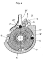
- Fig. 4 shows another embodiment of the drum 7 and the device according to the invention, wherein in Fig. 4, a corresponding section in a schematic representation as shown in Fig. 3 is shown.
- the difference 3 the filter element feed 21 is arranged in the 12 o'clock position and in that the direction of rotation 17 'is opposite to the direction of rotation 17 shown in FIG.
- the introduced into the receiving trough 19 in the filter element feed 21 filter element is braked by means of a braking element 20 'in the form of a brake plate.
- the light barrier consisting of the light emitting diode 10 and the detector 11, arranged longitudinally axially to the conveying direction of the filter elements, so that the rotational movement of the drum 7 can already begin before the filter element 6 completely into the receiving trough 19 of Drum 7 was moved. A complete deceleration is thus provided after startup or after the start of the rotation of the drum 7 on the brake element 20 '.
- the comb 22 ' is designed differently than the comb 22 of FIG. 3. Also in this embodiment, a gentle transfer is given by the relatively gentle flanks of both the comb 22' and the receiving wells 19.
- FIG. 5 shows a development of the device according to the invention according to FIG. 4 in a schematic sectional illustration.
- the ejection of defective filter elements 6 is provided with a flap 23 which opens upon detection of a defective filter element in a position 23 'by rotation about the axis of rotation 24 to transfer the filter element 6, which is defective, into a collecting container 9 ,
- Fig. 6 shows a schematic sectional view of an inventive arrangement of the inventive devices, wherein three inventive arrangements are provided.
- the devices according to the invention are arranged obliquely one above the other and adjoin the filter element magazine 8.
- the filter element magazine 8 is limited by magazine walls 25 and just the devices of the invention. It is also schematically illustrates the disposal direction 26 of the defective filter elements.
- Fig. 7 shows a further arrangement according to the invention of the devices according to the invention, in which the devices according to the invention are arranged vertically one above the other.
- the drum 7 To supply filter elements of the drum 7, they are first accelerated longitudinally by means of the acceleration rollers 4. For this purpose, the drum 7 is in a position in which the accelerated filter element 6 can reach the receiving trough 19 of the drum 7.
- the radial acceleration of the drum begins at the moment in which the filter element has left the light barrier. Subsequently, the drum 7 is braked to provide the next receiving well for the next filter element. Before the start of the rotation (embodiment of FIG. 3) or after the start of the rotation (embodiment of FIG. 4), the filter element is decelerated in the receiving trough.
- a circumferentially placed mechanical brake plate 20 according to FIG. 4 can be used, which is in particular adjustable and which acts radially on the filter element and brakes the filter element more rapidly with an increasing angle of rotation.
- the braking can also be done by means of a frontally arranged compressed air nozzle. This is operated, for example clocked, the control can be done via a photoelectric sensor 10, 11.
- the filter element is aligned transaxially by longitudinal axial displacement in the receiving trough 19.
- the transverse axial alignment can be done both mechanically and pneumatically. It is also possible in the embodiment of FIG. 4, that the alignment by the brake plate 20 'is made.
- the filter element is pushed out of the drum by the interaction of the receiving trough flank and the fork.
- the receiving wells should be designed so that when accelerating the drum does not load the entire filter load from the magazine on the drum bar and the filter element to be introduced into the magazine. For this reason, a relatively long flank is provided in the receiving trough, which holds the filter elements in the filter element magazine during acceleration of the drum.
- the drum is in the braking phase. During braking, the back pressure of the filter elements in the magazine helps.
- a filter lock used in the prior art, for example in the Applicant's FILTROMAT 3 FE, becomes active.
- the drum is moved to a specific position stopped and as described above, the filter removed from the drum. This can be done by mechanical elements or by compressed air.
- the disposal of the filter rods located in the longitudinal transport of the filter receiver can be done either via the drum or between the accelerator roller and the drum. After a corresponding error removal, the device can be restarted fully automatically.
- FIG. 8 shows a schematic three-dimensional representation of a further receiving station according to the invention in a section.
- a filter element 6 has been fed through the holder 27 and an annular opening in the movable knife element 29 in the direction of the filter element feed 31 to a receptacle of the drum 7. If this is a defective filter element, which can be detected, for example, by the fact that the residence time in front of a light barrier 10, 11 (see FIG.
- a knife comprising a movable knife element 29 and a fixed Knife element 30 to shear off or cut off this filter element accordingly.
- the in the Received part of the filter element 6 can then be disposed of as just described.
- the part remaining in the feeding channel 5 ' is then blown out of the channel 5' by opening a flap and applying compressed air in the opposite direction to the feeding direction 31.
- the corresponding drum grooves or receptacles 33 are checked by means of a light barrier, whether filter elements or parts thereof remain in the grooves or receptacles.
- a corresponding light barrier is not shown in the figures. This light barrier can be arranged at a suitable location in the receptacle. A corresponding light barrier can also be arranged at a suitable location in the channel 5 '.
- a comb 22 "is still shown schematically, by means of which the filter element 6 located at the top in FIG. 8 can be specifically, defined and gently transferred into a filter element supply, not shown.
Abstract
Description
Die Erfindung betrifft eine Vorrichtung zur Förderung von stabförmigen Filterelementen zu einem Filterelementmagazin, wobei längsaxial zuführbare Filterelemente queraxial dem Filterelementmagazin zuführbar sind, und wobei eine queraxial drehbare Trommel mit wenigstens einer Aufnahme für ein Filterelement vorgesehen ist.The invention relates to a device for conveying rod-shaped filter elements to a filter element magazine, wherein longitudinal axial feedable filter elements are fed queraxial the filter element magazine, and wherein a queraxial rotatable drum is provided with at least one receptacle for a filter element.
Die Erfindung betrifft ferner ein Verfahren zur Steuerung der Förderung von Filterelementen zu einem Filterelementmagazin.The invention further relates to a method for controlling the conveyance of filter elements to a filter element magazine.
Eine entsprechende Vorrichtung zur Förderung von stabförmigen Filterelementen ist beispielsweise aus der JP 54-13195 bekannt. Dieses Dokument offenbart einen Filterempfänger mit einem Flügelrad, in dem iängsaxiai ankommende Filterstäbe mit Saugluft abgebremst werden. Das Flügelrad wird hierbei intermittierend angetrieben und gibt die Filterstäbe an einen Bandförderer ab.A corresponding device for conveying rod-shaped filter elements is known for example from JP 54-13195. This document discloses a filter receiver with an impeller in which iängsaxiai arriving filter rods are slowed down with suction air. The The impeller is driven intermittently and delivers the filter rods to a belt conveyor.
Eine weitere bekannte Vorrichtung zur Förderung von stabförmigen Filterelementen zu einem Filterelementmagazin bzw. ein entsprechendes Verfahren zur Förderung von Filterelementen zu einem Filterelementmagazin ist durch das sogenannte Filterstab-Beschickungssystem FILTROMAT 3 FE der Anmelderin bekannt. Ein derartiges Filterstab-Beschickungssystem bzw. ein derartiger Filterstabempfänger empfängt längsaxial Filterstäbe, die zunächst abgebremst werden, um dann längsaxial beschleunigt zu werden. Anschließend werden dem Filtermagazin Filterstäbe queraxial zugeführt. Hierbei sind verschiedene Modulvarianten bekannt. Es existieren beispielsweise Einzelempfänger, Doppelempfänger und Dreifachempfänger. Es ist hierbei möglich, in Abhängigkeit des Bedarfs der Filterstäbe die Geschwindigkeit des Filterstab-Empfängers zu regeln.Another known device for conveying rod-shaped filter elements to a filter element magazine or a corresponding method for conveying filter elements to a filter element magazine is known by the so-called filter rod feeding system FILTROMAT 3 FE the applicant. Such a filter rod feed system or such a filter rod receiver receives longitudinally filter rods, which are first decelerated, to then be longitudinally accelerated axially. Subsequently filter rods are fed transaxially to the filter magazine. Here, various module variants are known. There are, for example, individual receiver, double receiver and triple receiver. It is possible in this case to regulate the speed of the filter rod receiver depending on the requirement of the filter rods.
Bei der Herstellung von Multisegmentfiltern mit einer aus Modulen bestehenden Einrichtung, die bspw. aus der DE 101 55 292.0 der Anmelderin bekannt ist, ist die Verwendung des FILTROMAT 3 FE aufgrund der Baugröße problematisch.In the production of multi-segment filters with a device consisting of modules, which is known, for example, from DE 101 55 292.0 of the Applicant, the use of the FILTROMAT 3 FE is problematic due to the size.
Es ist Aufgabe der vorliegenden Erfindung eine Vorrichtung zur Förderung von stabförmigen Filterelementen zu einem Filterelementmagazin und ein entsprechendes Verfahren zur Steuerung der Förderung der Filterelemente zu einem Filterelementmagazin derart weiterzubilden, dass eine auf sehr kleinem Raum stattfindende und effektive Förderung der stabförmigen Filterelemente möglich ist.It is an object of the present invention to develop a device for conveying rod-shaped filter elements to a filter element magazine and a corresponding method for controlling the promotion of the filter elements to a filter element magazine such that a taking place in a very small space and effective promotion of rod-shaped filter elements is possible.
Gelöst wird diese Aufgabe durch eine Vorrichtung zur Förderung von stabförmigen Filterelementen, insbesondere Filterstäben, zu einem Filterelementmagazin, wobei längsaxial förderbare Filterelemente queraxial dem Filterelementmagazin zuführbar sind, wobei eine drehbare Trommel mit wenigstens einer Aufnahme für ein Filterelement vorgesehen ist, die dadurch weitergebildet ist, dass die Drehung der Trommel über eine die Filterelemente erfassende Detektionsvorrichtung steuerbar ist. Die erfindungsgemäße Vorrichtung ist sehr kompakt bauend realisierbar, wobei die Filterelemente sehr effektiv und auch sehr schnell und kontrolliert dem Filterelementmagazin zuführbar sind. Durch Vorsehen einer Detektionsvorrichtung kann der Takt der Drehung der Trommel im Verhältnis sehr hoch eingestellt werden.This object is achieved by a device for conveying rod-shaped filter elements, in particular filter rods, to a filter element magazine, wherein longitudinally axially conveyable filter elements are transaxially fed to the filter element magazine, wherein a rotatable drum is provided with at least one receptacle for a filter element, which is further developed in that the rotation of the drum via a filter elements detecting the detection device is controllable. The device according to the invention can be realized in a very compact design, wherein the filter elements can be fed to the filter element magazine very effectively and also very quickly and in a controlled manner. By providing a detection device, the clock of the rotation of the drum can be set very high in relation.
Eine besonders einfach zu realisierende Vorrichtung ist dann gegeben, wenn die Detektionsvorrichtung eine Lichtschranke umfasst. Mittels der Lichtschranke können der Anfang und das Ende durch die Detektionsvorrichtung bzw. an der Detektionsvorrichtung vorbei geförderter Filterelemente detektiert werden, wodurch die drehbare Trommel entsprechend gesteuert werden kann. Vorzugsweise ist die Detektionsvorrichtung zur Trommel beabstandet angeordnet, so dass zu einem Zeitpunkt, an dem die Filterelemente noch nicht vollständig in die jeweilige Aufnahme der Trommel gefördert wurde, schon mit der Drehung der Trommel begonnen werden kann, wodurch eine schnellere Förderung möglich ist.A particularly easy-to-implement device is provided when the detection device comprises a light barrier. By means of the light barrier, the beginning and the end of the detection device or on the detection device conveyed past filter elements can be detected, whereby the rotatable drum can be controlled accordingly. Preferably, the detection device is arranged spaced from the drum, so that at a time at which the filter elements has not been fully promoted in the respective recording of the drum, already with the rotation of the drum can be started, whereby a faster delivery is possible.
Wenn die Trommel mit einem mechanischen Element zusammenwirkt, das ein queraxiales Einschieben der Filterelemente in das Filterelementmagazin bewirkt, ist eine sehr schonende Förderung der Filterelemente in das Filterelementmagazin möglich. Als mechanisches Element kommt beispielsweise eine Gabel oder ein Kamm in Betracht, die in die Aufnahmen der Trommel eingreifen und ein festes Hindernis für den Verbleib der Filterelemente in den jeweiligen Aufnahmen bei weiterer Drehung der Trommel darstellen.If the drum cooperates with a mechanical element which causes a transverse axial insertion of the filter elements in the filter element magazine, a very gentle promotion of the filter elements in the filter element magazine is possible. As a mechanical element is for example a fork or a comb into consideration, which engage in the receptacles of the drum and constitute a solid obstacle to the whereabouts of the filter elements in the respective recordings upon further rotation of the drum.
Eine besonders definierte Förderung, die störungssicher ist, ist dann gegeben, wenn die Förderung der Filterelemente zur Trommel über ortsfest angeordnete Elemente erfolgt. Die ortsfest angeordneten Elemente sind hierbei Rohre oder Rohrleitungen, durch die die Filterelemente längsaxial gefördert werden, Bremsräder zum Abbremsen der Filterelemente, Beschleunigungsräder zum Beschleunigen der Filterelemente in längsaxialer Richtung und eine beispielsweise gerade Förderbahn stromabwärts der Bremsräder.A particularly defined promotion, which is trouble-free, is given when the promotion of the filter elements to the drum via stationary arranged elements. The stationary arranged elements here are pipes or pipes through which the filter elements are conveyed longitudinal axial, brake wheels for braking the filter elements, acceleration wheels for accelerating the filter elements in the longitudinal axial direction and an example straight conveyor track downstream of the brake wheels.
Wenn mehrere Aufnahmen in der Trommel vorgesehen sind, wobei die Aufnahmen insbesondere Mulden sind, ist eine sehr schnelle Förderung von Filterelementen möglich.If several receptacles are provided in the drum, the receptacles are in particular troughs, a very fast promotion of filter elements is possible.
Vorzugsweise ist ein Bremselement zum Abbremsen des in die Aufnahme der Trommel bewegbaren Filterelements vorgesehen, wodurch eine schonende Förderung der Filterelemente in die Aufnahmen der Trommel möglicht ist. Bei dem Bremselement kann es sich um ein mechanisches Element, wie ein Bremsblech handeln, das radial auf die stabförmigen Filterelemente drückt bzw. um einen Auflaufteil, der stirnseitig auf den Umfang des Filterelements drückt. Es kann sich auch um ein pneumatisches Element handeln, das beispielsweise Druckluft pneumatisch getaktet in die zur Aufnahme der Filterelemente vorgesehenen Aufnahmen einlässt, um die Filterelemente entsprechend abzubremsen. Das Abbremsen der längsaxial bewegten Filterelemente kann zweckmäßigerweise stirnseitig pneumatisch erfolgen, wobei bspw. eine Düse an der Stirnseite einer Aufnahme angeordnet ist, wobei Druckluft aus der Düse auf das in Bewegungsrichtung vordere Ende des Filterelements wirkt. Dieses Abbremsen eignet sich besonders für empfindliche Filterelemente.Preferably, a braking element is provided for braking the movable in the receptacle of the drum filter element, whereby a gentle promotion of the filter elements in the receptacles of the drum is made possible. The braking element can be a mechanical element, such as a brake plate, which presses radially onto the rod-shaped filter elements or around a run-on part, which presses the end face onto the circumference of the filter element. It may also be a pneumatic element which, for example, pneumatically actuates compressed air in the receptacles provided for receiving the filter elements in order to decelerate the filter elements accordingly. The braking of the longitudinally moved axially filter elements can advantageously be carried out pneumatically on the front side, wherein, for example, a nozzle is arranged on the end face of a receptacle, compressed air from the nozzle acting on the front in the direction of movement of the filter element. This braking is particularly suitable for sensitive filter elements.
Das Schalten der Druckluft geschieht vorzugsweise mit einem Schnellschaltventil bspw. der Marke FESTO. Das Ventil wird hierbei über ein Lichtschranke am Trommeleintritt gesteuert bzw. getaktet.The switching of the compressed air is preferably done with a quick-acting valve, for example. The brand FESTO. The valve is controlled or clocked via a light barrier at the drum inlet.
Vorzugsweise ist die Trommel drehbar, bevor das Filterelement seine Endposition in der Aufnahme der Trommel erreicht hat. Hierzu ist vorzugsweise die Steuerung in der Gestalt realisiert, dass die Drehung der Trommel schon vor dem vollständigen Hineinbewegen des Filterelements beginnt. Mittels dieser vorzugsweisen Ausgestaltung der vorliegenden Erfindung ist eine besonders schonende Bremsung der Filterelemente möglich. Vorzugsweise umfasst die Trommel wenigstens ein Element zum Ausrichten der Filterelemente. Durch diese Maßnahme können die Filterelemente bündig dem Filtermagazin zugeführt werden.Preferably, the drum is rotatable before the filter element has reached its end position in the receptacle of the drum. For this purpose, the control is preferably realized in the form that the rotation of the drum begins even before the filter element is completely moved in. By means of this preferred embodiment of the present invention, a particularly gentle braking of the filter elements is possible. Preferably, the drum comprises at least one element for aligning the filter elements. By this measure, the filter elements can be flush fed to the filter magazine.
Wenn ein Auswurfmechanismus für defekte Filterelemente vorgesehen ist, kann der Ausschuss an beispielsweise defekten Filterzigaretten, für die die entsprechenden Filterelemente vorgesehen sind, minimiert werden. Es ist vorzugsweise eine Art Selbstreinigung der Filterelementempfangsstation vorgesehen. Hierzu ist bspw. ein mit der Trommel rotierendes Schneidelement, bspw. ein rotierender Schneidring, vorgesehen, der einen teilweise in die Trommel eingetretenen Filterstab beim Weiterdrehen der Trommel um eine Position zerschneidet. Das Schneidelement umfasst wie erwähnt den mit der Trommel rotierenden Schneidring und ein feststehendes Schneidelement. Der im Längstransport verbleibende hintere Teil des Filterstabs wird dann bspw. mittels eines Luftdruckes zurückgeblasen und durch Öffnen einer entsprechenden hierfür vorgesehenen Klappe ausgeworfen. Hierzu kann auch eine Schiene geöffnet werden, die im unteren Bereich eines zum Längstransport verwendeten Elements vorgesehen ist, das in Förderrichtung kurz vor der Trommel angeordnet ist. Der vordere Teil des Filterelements wird bspw. zwei Positionen der Trommel weiter transportiert und aus der Trommel dann ausgeblasen.If an ejection mechanism is provided for defective filter elements, the scrap can be minimized on, for example, defective filter cigarettes for which the corresponding filter elements are provided. It is preferably provided a kind of self-cleaning of the filter element receiving station. For this purpose, for example, a rotating with the drum cutting element, for example. A rotating cutting ring is provided which cuts a partially entered into the drum filter rod during further rotation of the drum to a position. The cutting element comprises, as mentioned, the rotating with the drum cutting ring and a fixed cutting element. The remaining in the longitudinal transport rear part of the filter rod is then, for example, blown back by means of an air pressure and ejected by opening a corresponding flap provided for this purpose. For this purpose, a rail can be opened, which is provided in the lower region of an element used for longitudinal transport, which is arranged in the conveying direction just before the drum. The front part of the filter element is, for example, transported further two positions of the drum and then blown out of the drum.
Nach der Selbstreinigung wird die entsprechende Trommelnut bzw. die entsprechende Trommelaufnahme bspw. mittels einer Lichtschranke kontrolliert, um festzustellen, ob noch Teile des Filterelements in der Aufnahme enthalten sind.After the self-cleaning, the corresponding drum groove or the corresponding drum holder, for example. Checked by a photocell to determine whether any parts of the filter element are included in the recording.
Eine erfindungsgemäße Filterelementempfangsstation umfasst eine der erfindungsgemäßen Vorrichtung bzw. eine bevorzugte Ausführungsform der erfindungsgemäßen Vorrichtung, die vorstehend beschrieben wurde.A filter element receiving station according to the invention comprises one of the device according to the invention or a preferred embodiment of the device according to the invention which has been described above.
Eine bevorzugte Anordnung zur Förderung von Filterelementen zu einem Filterelementmagazin mit wenigstens einer der erfindungsgemäßen Vorrichtung ist dergestalt, dass die Vorrichtung außerhalb des Filterelementmagazins angeordnet ist. Durch diese bevorzugte Anordnung können sehr effektiv defekte Filterelemente von der weiteren Verfahrensführung ausgeschlossen werden. Es ist ferner möglich, bei Anordnungen zur Herstellung von Multisegmentfiltem die entsprechenden Module, mittels der entsprechenden Segmente oder Gruppen von Segmenten zur Herstellung der Multisegmentfilter zusammengestellt werden, derart auszugestalten, dass die entsprechenden Module schmal konstruiert sein können. Vorzugsweise sind mehrere Vorrichtungen, insbesondere drei Vonichtungen erfindungsgemäß angeordnet. In einer weiteren bevorzugten Ausführungsform der erfindungsgemäßen Anordnung sind die Vorrichtungen untereinander angeordnet, wodurch eine noch schmalere Bauweise der Anordnung möglich ist.A preferred arrangement for conveying filter elements to a filter element magazine with at least one of the device according to the invention is such that the device is arranged outside the filter element magazine. By means of this preferred arrangement, defectively defective filter elements can be excluded from further process control. It is also possible, in arrangements for the production of multi-segment filters, to assemble the corresponding modules by means of the corresponding segments or groups of segments for the production of the multi-segment filters in such a way that the corresponding modules can be constructed narrow. Preferably, a plurality of devices, in particular three devices are arranged according to the invention. In a further preferred embodiment of the arrangement according to the invention, the devices are arranged one below the other, whereby an even narrower construction of the arrangement is possible.
Die Aufgabe wird ferner durch ein Verfahren zur Steuerung der Förderung von stabförmigen Filterelementen zu einem Filterelementmagazin gelöst, das die folgenden Verfahrensschritte aufweist:
- Fördern von Filterelementen in längsaxialer Richtung zu einer Trommel mit wenigstens einer Aufnahme für ein Filterelement, insbesondere zu einer Vorrichtung nach einem oder mehreren Ansprüchen 1 bis 9,
- Vorbeiführen der Filterelemente an einer Detektionsvorrichtung,
- Erzeugen eines Startsignal, sobald das Ende eines Filterelements die Detektionsvorrichtung passiert hat,
- Beginnen einer Drehung der Trommel in queraxialer Richtung nach Erhalt des Startsignals, und
- Einschieben des Filterelements in das Filterelementmagazin.
- Conveying filter elements in the longitudinal axial direction to a drum having at least one receptacle for a filter element, in particular to a device according to one or more of claims 1 to 9,
- Passing the filter elements on a detection device,
- Generating a start signal as soon as the end of a filter element has passed the detection device,
- Starting a rotation of the drum in the transverse axial direction after receiving the start signal, and
- Insert the filter element into the filter element magazine.
Durch dieses Verfahren ist eine sehr effektive, verlässliche und schnelle Förderung von stabförmigen Filterelementen zu einem Filterelementmagazin möglich.By this method, a very effective, reliable and fast promotion of rod-shaped filter elements to a filter element magazine is possible.
Vorzugsweise wird die Trommel um 360° geteilt durch die Anzahl der Aufnahmen auf der Trommel gedreht. Wenn zum Ende der Drehung eine Abbremsung geschieht, ist eine schonende Förderung der Filterelemente bzw. ein schonendes Einbringen der Filterelemente in das Filterelementmagazin möglich. Die Abbremsung kann hierbei vorzugsweise wenigstens teilweise mit Hilfe der Gewichtskraft der im Filterelementmagazin angeordneten Filterelemente geschehen.Preferably, the drum is rotated by 360 ° divided by the number of shots on the drum. If a deceleration occurs at the end of the rotation, a gentle conveyance of the filter elements or a gentle introduction of the filter elements into the filter element magazine is possible. The deceleration may in this case preferably take place at least partially with the aid of the weight of the filter elements arranged in the filter element magazine.
Wenn die Güte der Filterelemente geprüft wird, wobei fehlerhafte Filterelemente ausgeschleust werden, wird der Ausschuss an entsprechend herzustellenden Filterzigaretten minimiert. Eine besonders einfache Überprüfung der Güte ist dann möglich, wenn zur Prüfung der Güte der Filterelemente die Länge der Verweildauer der Filterelemente an der Detektionsvorrichtung gemessen wird. Vorzugsweise wird ab einer von der Fördergeschwindigkeit abhängigen und vorgebbaren Verweildauer das dieser Verweildauer zugeordnete Filterelement ausgeschleust. Das Ausschleusen geschieht somit dann, wenn die Verweildauer des Filterelements größer ist als eine von der Fördergeschwindigkeit abhängige und vorgebbare Verweildauer. Auf der anderen Seite wird vorzugsweise bis zu einer von der Fördergeschwindigkeit abhängigen und vorgebbaren Verweildauer das dieser Verweildauer zugeordnete Filterelement in das Filterelementmagazin gefördert.If the quality of the filter elements is checked, with faulty filter elements are discharged, the waste is minimized to appropriately manufactured filter cigarettes. A particularly simple check of the quality is possible if the length of the residence time of the filter elements on the detection device is measured to check the quality of the filter elements. The filter element assigned to this residence time is preferably discharged from a residence time that is dependent on the delivery speed and can be predetermined. The discharge thus takes place when the residence time of the filter element is greater than a dependent of the conveying speed and predetermined residence time. On the other hand, the filter element associated with this residence time is preferably conveyed into the filter element magazine up to a residence time which is dependent on the conveying speed and can be predetermined.
Die Erfindung wird nachstehend und ohne Beschränkung des allgemeinen Erfindungsgedankens anhand der Zeichnungen beschrieben. Bezüglich aller im Text nicht näher erläuterten erfindungsgemäßen Einzelheiten wird auf die Zeichnungen verwiesen. Es zeigen:
- Fig. 1
- eine schematische Seitenansicht einer erfindungsgemäßen Empfangsstation,
- Fig. 2
- einen Teil aus Fig. 1 in vergrößerter Darstellung,
- Fig. 3
- eine schematische Schnittdarstellung entlang des Schnitts A-A der Fig. 2,
- Fig. 4
- eine andere erfindungsgemäße Ausgestaltung einer Trommel in einer Schnittdarstellung,
- Fig. 5
- eine weitere erfindungsgemäße Ausgestaltung einer Trommel in einer schematischen Schnittdarstellung,
- Fig.6
- eine erfindungsgemäße Anordnung in schematischer Schnittdarstellung,
- Fig. 7
- eine weitere erfindungsgemäße Anordnung in einer schematischen Schnittdarstellung, und
- Fig. 8
- eine schematische dreidimensionale Darstellung eines Ausschnitts einer weiteren erfindungsgemäßen Empfangsstation.
- Fig. 1
- a schematic side view of a receiving station according to the invention,
- Fig. 2
- a part of Fig. 1 in an enlarged view,
- Fig. 3
- 3 is a schematic sectional view along section AA of FIG. 2,
- Fig. 4
- another embodiment of a drum according to the invention in a sectional view,
- Fig. 5
- a further embodiment of a drum according to the invention in a schematic sectional view,
- Figure 6
- an inventive arrangement in a schematic sectional view,
- Fig. 7
- a further inventive arrangement in a schematic sectional view, and
- Fig. 8
- a schematic three-dimensional representation of a section of another receiving station according to the invention.
Fig. 1 zeigt einen Filterelementempfänger zur Förderung von stabförmigen Filterelementen 6 in ein Filterelementmagazin 8. Die in das Filterelementmagazin 8 eingeführten Filterelemente 6 dienen dazu, nachdem diese beispielsweise in Filterelemente zweifacher Gebrauchslänge geschnitten wurden, mit einem Tabakstock zweifacher Gebrauchslänge zusammengeführt zu werden, um Filterzigaretten herzustellen. Die in das Filterelementmagazin 8 zugeführten Filterelemente 6 können auch dazu dienen, in entsprechende Filtersegmente zerschnitten und einer Anordnung von Filtersegmenten zur Herstellung von Multisegmentfiltern zugeführt zu werden. Die erfindungsgemäße Einrichtung kann hierzu mehreren oder sämtlichen Funktionseinheiten einer Einrichtung zum Zusammenstellen von Gruppen von Filtersegmenten zur Herstellung von Multisegmentfiltern der tabakverarbeitenden Industrie gemäß der DE 101 55 292.0 der Anmelderin zugeordnet sein. Die DE 101 55 292.0 soll vollumfänglich in den Offenbarungsgehalt dieser Patentanmeldung aufgenommen sein.Fig. 1 shows a filter element receiver for conveying rod-shaped
Die Filterelemente n-facher Gebrauchslänge werden über eine Rohrleitung von einer Filterherstellmaschine mittels eines Filterelementsenders einer Anschlußleitung 1 zugeführt. Die Rohrleitung ist in Fig. 1 nicht dargestellt. Die Filterelemente 6, die beabstandet in dem Zuführrohr zur Anschlussleitung 1 gefördert werden, gelangen dann in eine Bogenführung 2, um mittels Bremsrollen 3 in einem Kanal 5 abgebremst zu werden. Anschließend werden die Filterelemente 6 mittels einer Beschleunigerrolle 4 über eine nicht dargestellte Führung in eine Trommel 7 gefördert. Die Trommel 7 und die weiteren Elemente dazu, die erfindungswesentlich sind, sind in Fig. 2 in einer vergrößerten schematischen Darstellung eines Ausschnitts aus Fig. 1 besser dargestellt. In Fig. 2 ist die Trommel 7 mit einem Filterelement 6 in einer Aufnahmemulde 19 dargestellt. Das Filterelement 6 hat in diesem Verfahrenszustand eine Lichtschranke bestehend aus einer Leuchtdiode 10 und einem Detektor 11 schon passiert. Die Trommel 7 ist auf den Lagern 12 gelagert und wird um die Drehachse 13 gedreht und kann, sofern es sich bei dem Filterelement um ein fehlerhaftes Filterelement handelt, das Filterelement aus dem Ausblaskanal 16, der durch das Gehäuse 18 und die Aufnahmemulde 19 gebildet wird, in Ausblasrichtung 15 mit Druckluft ausblasen, so dass dieses defekte Filterelement einem Auf fangbehälter 9 zugeführt wird. Zur Zuführung von Druckluft ist ein Druckluftanschluss 14 vorgesehen.The filter elements n-times use length are fed via a pipe from a Filterherstellmaschine means of a filter element transmitter a connection line 1. The pipeline is not shown in Fig. 1. The
Sofern das Filterelement nicht beschädigt bzw. defekt ist, wird das Filter element, das in der Aufnahme 19 angeordnet ist, über die Drehbewegung der Trommel 7 weitergefördert und dem Magazin 8 zugeführt. Dieses wird im folgenden näher beschrieben. Die Leuchtdiode 10 und der Detektor 11 sind in einer Halterung 27 gehalten. Die Leuchtdiode 10 und der Detektor 11 bilden eine Lichtschranke.If the filter element is not damaged or defective, the filter element, which is arranged in the
In einer Ausführungsform der erfindungsgemäßen Vorrichtung, die in Fig. 3 dargestellt ist, wird das Filterelement 6 in einer Filterelementzuführung 21 in einer 3-Uhr-Stellung in die dort sich befindende Aufnahmemulde längsaxial eingeführt. Nach Passieren der Lichtschranke, bestehend aus der Leuchtdiode 10 und dem Detektor 11 beginnt die Trommel 7 sich in Drehrichtung 17 zu drehen. Vor der Drehung hat das Bremselement 20 das Filterelement 6 in der Aufnahmemulde 19 abgebremst, und zwar im wesentlichen durch Krafteinwirkung auf die stirnseitige Umfangsfläche des Filterelements 6. Die Stirnseite ist dem Betrachter der Fig. 3 entgegengerichtet. Durch Messen der Verweildauer des Filterelements in der Lichtschranke kann festgestellt werden, ob der Filter defekt (z.B. aufgeplatzt) ist oder den gewünschten Parametern entspricht. Sollte der Filter defekt sein, kann dieser in der 6-Uhr-Stellung beispielsweise durch Blasluft ausgeworfen werden. Alternativ ist es möglich, den defekten Filter in 3-Uhr-Stellung auszuwerfen. Hierzu bleibt die Trommel 7 stehen, das Filterelement 6 wird zurückgeblasen, die nicht dargestellte Führung schwenkt weg und das Filterelement 6 fällt raus. Im weiteren Verlauf der Drehung der Trommel kann das Filterelement 6 durch ein übliches Ausrichtelement, wie beispielsweise ein Blech, ausgerichtet werden. Ab der Position von 12-Uhr wird das Filterelement 6 schonend in einen Kanal 28, der durch das Gehäuse 18 und den Kamm 22 gebildet wird, übergeben. Durch die entsprechende sanfte Steigung des Kamms 22 in Verbindung mit der flachen Flanke der Aufnahmemulde 19 in Förderrichtung ist eine schonende Übergabe des Filterelements 6 in den Kanal 28 möglich. Der Kamm 22 greift teilweise in die Aufnahmemulden der Trommel 7 ein. Fig. 3 ist eine schematische Schnittdarstellung entlang des Schnittes A-A der Fig. 2.In one embodiment of the device according to the invention, which is shown in Fig. 3, the
Fig. 4 zeigt eine andere Ausführungsform der Trommel 7 bzw. der erfindungsgemäßen Vorrichtung, wobei in Fig. 4 auch ein entsprechender Schnitt in schematischer Darstellung wie in Fig. 3 dargestellt ist. Der Unterschied zu Fig. 3 besteht zum einen darin, dass die Filterelementzuführung 21 in 12-Uhr-Position angeordnet ist und darin dass die Drehrichtung 17' entgegengesetzt zur in Fig. 3 dargestellten Drehrichtung 17 ist. Das in die Aufnahmemulde 19 bei der Filterelementzuführung 21 eingeführte Filterelement wird mittels eines Bremselements 20' in Form eines Bremsbleches abgebremst. Hierbei ist zu berücksichtigen, dass vorzugsweise die Lichtschranke, bestehend aus der Leuchtdiode 10 und dem Detektor 11, längsaxial zur Förderrichtung der Filterelemente beabstandet angeordnet ist, so dass die Drehbewegung der Trommel 7 schon beginnen kann, bevor das Filterelement 6 vollständig in die Aufnahmemulde 19 der Trommel 7 bewegt wurde. Ein vollständiges Abbremsen ist somit nach Ingangsetzung bzw. nach Beginn der Drehung der Trommel 7 an dem Bremselement 20' vorgesehen.Fig. 4 shows another embodiment of the
In Fig. 4 ist der Kamm 22' anders ausgestaltet als der Kamm 22 der Fig. 3. Auch in diesem Ausführungsbeispiel ist eine schonende Übergabe durch die relativ sanften Flanken sowohl des Kamms 22' als auch der Aufnahmemulden 19 gegeben.In FIG. 4, the comb 22 'is designed differently than the
Fig. 5 zeigt eine Weiterbildung der erfindungsgemäßen Vorrichtung gemäß Fig. 4 in schematischer Schnittdarstellung. In diesem Ausführungsbeispiel ist der Auswurf von defekten Filterelementen 6 mit einer Klappe 23 vorgesehen, die bei Detektion eines defekten Filterelements in eine Position 23' durch Rotation über die Drehachse 24 aufklappt, um das Filterelement 6, das defekt ist, in einen Auffangbehälter 9 zu überführen.FIG. 5 shows a development of the device according to the invention according to FIG. 4 in a schematic sectional illustration. In this embodiment, the ejection of
Fig. 6 zeigt eine schematische Schnittdarstellung einer erfindungsgemäßen Anordnung der erfindungsgemäßen Vorrichtungen, wobei drei erfindungsgemäße Anordnungen vorgesehen sind. Die erfindungsgemäßen Vorrichtungen sind schräg übereinander angeordnet und grenzen an das Filterelementmagazin 8 an. Das Filterelementmagazin 8 ist begrenzt durch Magazinwände 25 und eben die erfindungsgemäßen Vorrichtungen. Es ist ferner schematisch die Entsorgungsrichtung 26 der defekten Filterelemente darstellt.Fig. 6 shows a schematic sectional view of an inventive arrangement of the inventive devices, wherein three inventive arrangements are provided. The devices according to the invention are arranged obliquely one above the other and adjoin the
Fig. 7 zeigt eine weitere erfindungsgemäße Anordnung der erfindungsgemäßen Vorrichtungen, bei der die erfindungsgemäßen Vorrichtungen vertikal übereinander angeordnet sind.Fig. 7 shows a further arrangement according to the invention of the devices according to the invention, in which the devices according to the invention are arranged vertically one above the other.
Durch Vorsehen einer Trommel mit Aufnahmemulden für Filterelemente ist eine formschlüssige Erzeugung der Einschubkraft der Filterelemente in das Filterelementmagazin möglich. Somit ist die Erzeugung größerer Einschubkräfte gegeben.By providing a drum with receiving wells for filter elements, a positive production of the insertion force of the filter elements in the filter element magazine is possible. Thus, the generation of larger insertion forces is given.
Um Filterelemente der Trommel 7 zuzuführen, werden diese zunächst längsaxial mittels der Beschleunigungsrollen 4 beschleunigt. Die Trommel 7 steht hierzu in einer Position, in der das beschleunigte Filterelement 6 in die Aufnahmemulde 19 der Trommel 7 gelangen kann.To supply filter elements of the
In einer bevorzugten Ausführungsform beginnt die radiale Beschleunigung der Trommel in dem Moment, in dem das Filterelement die Lichtschranke verlassen hat. Anschließend wird die Trommel 7 abgebremst, um die nächste Aufnahmemulde für das nächste Filterelement bereitzustellen. Vor Beginn der Drehung (Ausführungsbeispiel der Fig. 3) bzw. nach Beginn der Drehung (Ausführungsbeispiel der Fig. 4) wird das Filterelement in der Aufnahmemulde abgebremst. Als Bremselement kann ein am Umfang plaziertes mechanisches Bremsblech 20 gemäß der Fig. 4 Verwendung finden, das insbesondere einstellbar ist und das radial auf das Filterelement einwirkt und das Filterelement mit größer werdendem Drehwinkel stärker bremst.In a preferred embodiment, the radial acceleration of the drum begins at the moment in which the filter element has left the light barrier. Subsequently, the
Das Abbremsen kann auch mittels einer stirnseitig angeordneten Druckluftdüse geschehen. Diese wird bspw. getaktet betrieben, wobei die Steuerung über eine Lichtschranke 10, 11 geschehen kann.The braking can also be done by means of a frontally arranged compressed air nozzle. This is operated, for example clocked, the control can be done via a
Zwischen zwei Stopps wird das Filterelement durch längsaxiales Verschieben in der Aufnahmemulde 19 queraxial ausgerichtet. Das queraxiale Ausrichten kann sowohl mechanisch als auch pneumatisch geschehen. Es ist auch möglich in dem Ausführungsbeispiel gemäß Fig. 4, dass die Ausrichtung durch das Bremsblech 20' vorgenommen wird. Nach einer Drehung von ca. 350° wird das Filterelement durch das Zusammenwirken der Aufnahmemuldenflanke und der Gabel aus der Trommel herausgedrückt. Die Aufnahmemulden sollten derart ausgestaltet sein, dass beim Beschleunigen der Trommel nicht die gesamte Filterlast aus dem Magazin auf dem Trommelsteg und dem in das Magazin einzubringenden Filterelement lastet. Aus diesem Grund ist eine relativ lang gezogene Flanke in der Aufnahmemulde vorgesehen, die während der Beschleunigung der Trommel die Filterelemente im Filterelementmagazin hält. Beim Hineindrücken des Filterelements in das Magazin befindet sich die Trommel in der Bremsphase. Bei der Bremsung hilft der Gegendruck der im Magazin befindlichen Filterelemente.Between two stops, the filter element is aligned transaxially by longitudinal axial displacement in the receiving
Zur Entfernung von defekten Filterelementen wird über eine Lichtschranke 10,11 kontrolliert, wie lange sich das Filterelement 6 vor der Lichtschranke befindet. Bei einer Störung oder einem defekten Filter 6 ist die Lichtschranke 10, 11 länger als normal belegt. In diesem Fall stoppt der Längstransport sofort und eine im Stand der Technik beispielsweise bei dem FILTROMAT 3 FE der Anmelderin verwendete Filtersperre wird aktiv. Hierzu wird bspw. Bezug genommen auf die US-A-5 651 643. Zum Entferneun der defekten Filter wird die Trommel an einer bestimmten Position angehalten und wie vorstehend beschrieben, der Filter aus der Trommel entfernt. Dieses kann durch mechanische Elemente oder durch Druckluft geschehen. Die Entsorgung der im Längstransport des Filterempfängers befindlichen Filterstäbe kann entweder über die Trommel oder aber zwischen der Beschleunigerrolle und der Trommel geschehen. Nach einer entsprechenden Fehlerbeseitigung kann die Vorrichtung vollautomatisch wieder angefahren werden.To remove defective filter elements is controlled by a
Fig. 8 zeigt eine schematische dreidimensionale Darstellung einer weiteren erfindungsgemäßen Empfangsstation in einem Ausschnitt. Ein Filterelement 6 ist durch die Halterung 27 und eine ringförmige Öffnung in dem beweglichen Messerelement 29 in Richtung der Filterelementzuführung 31 einer Aufnahme der Trommel 7 zugeführt worden. Sofern es sich hierbei um eine defektes Filterelement handelt, was bspw. dadurch detektiert werden kann, dass die Verweildauer vor einer Lichtschranke 10, 11 (siehe Fig. 2) beim Transport des Filterelements in die Aufnahme der Trommel 7 einen zu langen Zeitraum in Anspruch nimmt oder einen zu kurzen, wird die Trommel 7 bspw. zwei Positionen weitergedreht und das in der Aufnahme liegende Filterelement bzw. ein Teil dieses Filterelements dann in die Filterelementausblasung 32 mittels Druckluft ausgeblasen und durch den Kanal 5' geführt, um so in einen Ausschussbehälter zu gelangen. Der Ausschussbehälter ist hier nicht dargestellt. Dieses funktioniert insbesondere dann, wenn das defekte Filterelement vollständig in die Aufnahme eingeführt wurde.FIG. 8 shows a schematic three-dimensional representation of a further receiving station according to the invention in a section. A
Bei einer bevorzugten Ausführungsform der Erfindung, bei der sich die Trommel 7 allerdings schon beginnt zu drehen, bevor das Filterelement vollständig in der Aufnahme eingebracht wurde, oder aber bei Filterelementen, die zu lang sind, dient ein Messer umfassend ein bewegliches Messerelement 29 und ein feststehendes Messerelement 30 dazu, dieses Filterelement entsprechend abzuscheren bzw. abzuschneiden. Der in die Aufnahme gelangte Teil des Filterelements 6 kann dann wie eben beschrieben entsorgt werden. Der in dem zuführenden Kanal 5' verbleibende Teil wird dann durch Öffnen einer Klappe und Beaufschlagen mit Druckluft in entgegengesetzter Richtung zur Zuführungsrichtung 31 aus dem Kanal 5' ausgeblasen.In a preferred embodiment of the invention, however, in which the
Es ist dann bevorzugt, dass nach der Selbstreinigung die entsprechenden Trommelnuten bzw. Aufnahmen 33 mittels einer Lichtschranke kontrolliert werden, ob noch Filterelemente oder Teile davon in den Nuten bzw. Aufnahmen verblieben sind. Eine entsprechende Lichtschranke ist in den Figuren nicht dargestellt. Diese Lichtschranke kann an geeigneter Stelle in der Aufnahme angeordnet sein. Eine entsprechende Lichtschranke kann auch an geeigneter Stelle in dem Kanal 5' angeordnet sein.It is then preferred that after the self-cleaning, the corresponding drum grooves or
In Fig. 8 ist noch schematisch ein Kamm 22" dargestellt, mittels dem das in Fig. 8 oben liegende Filterelement 6 gezielt, definiert und schonend in einen nicht dargestellten Filterelementvorrat übergeben werden kann.In FIG. 8, a
- 11
- Anschlussleitungconnecting cable
- 22
- Bogenführungbowing
- 33
- BremsrolleDrag reel
- 44
- Beschleunigerrolleaccelerator role
- 5, 5'5, 5 '
- Kanalchannel
- 66
- Filterelementfilter element
- 77
- Trommeldrum
- 88th
- Magazinmagazine
- 9, 9'9, 9 '
- Auffangbehälterreceptacle
- 1010
- Leuchtdiodeled
- 1111
- Detektordetector
- 1212
- Lagercamp
- 1313
- Drehachseaxis of rotation
- 1414
- DruckluftanschlussCompressed air connection
- 1515
- AusblasrichtungDischarge
- 1616
- Ausblaskanalblow-out
- 17, 17'17, 17 '
- Drehrichtungdirection of rotation
- 18, 18', 18"18, 18 ', 18 "
- Gehäusecasing
- 1919
- Aufnahmemuldereceiving trough
- 20, 20'20, 20 '
- Bremselementbraking element
- 2121
- FilterelementzuführungFilter element feed
- 22, 22', 22"22, 22 ', 22 "
- KammComb
- 2323
- Klappeflap
- 23'23 '
- Klappe in geöffneter StellungFlap in open position
- 2424
- Drehachseaxis of rotation
- 2525
- Magazinwandmagazine wall
- 2626
- Entsorgungsrichtungdisposal direction
- 2727
- Halterungbracket
- 2828
- Kanalchannel
- 2929
- bewegliches Messerelementmovable knife element
- 3030
- feststehendes Messerelementfixed knife element
- 3131
- FilterelementzuführungFilter element feed
- 3232
- FilterelementausblasungFilterelementausblasung
- 3333
- Aufnahmeadmission
Claims (19)
- Device for conveying tube-shaped filter elements (6), particularly filter tubes, to a filter-element magazine (8), filter elements (6) that can be conveyed in the direction of the longitudinal axis being able to be supplied in the direction of the transverse axis to the filter-element magazine (8), a rotatable drum (7) being provided with at least one receptacle (19, 33) for a filter element (6), characterized in that the rotation of the drum (7) is controllable through a detection device (10, 11) which detects the filter elements (6).
- Device according to claim 1, characterized in that the detection device (10, 11) comprises a photoelectric-beam detector (10, 11).
- Device according to claim 1 and/or claim 2, characterized in that the drum (7) acts together with a mechanical element (22, 22') which causes the filter elements (6) to be inserted, in the direction of the transverse axis, into the filter-element-magazine (8).
- Device according to one or more of claims 1 to 3, characterized in that the conveyance of the filter elements (6) to the drum (7) is effected through fixed elements (1-5, 5', 27).
- Device according to one or more of claims 1 to 4, characterized in that a plurality of receptacles (19, 33) are provided in the drum (7).
- Device according to one or more of claims 1 to 5, characterized in that a braking element (20, 20') is provided for braking the filter element (6) that can be moved into the receptacle (19, 33) of the drum (7).
- Device according to one or more of claims 1 to 6, characterized in that the drum (7) can be rotated before the filter element (6) has reached its end position in the receptacle (19, 33) of the drum (7).
- Device according to one or more of claims 1 to 7, characterized in that the drum (7) comprises an element for aligning the filter elements (6).
- Device according to one or more of claims 1 to 8, characterized in that an ejector (14, 15, 23) for defective filter elements (6) is provided.
- Filter-element receiving station having a device according to one or more of claims 1 to 9.
- Arrangement for conveying filter elements to a filterelement magazine (8), having at least one device according to one or more of claims 1 to 9, characterized in that the device is disposed outside the filter-element magazine (8).
- Arrangement according to claim 11, characterized in that a plurality of devices, in particular three devices, are provided.
- Arrangement according to claim 12, characterized in that the devices are disposed beneath one another.
- Method for controlling the conveyance of tube-shaped filter elements (6) to a filter-element magazine (8), having the following method steps:- conveyance of filter elements (6), in the direction of the longitudinal axis, to a drum (7) having receptacles (19) for filter elements (6), in particular to a device according to one or more of claims 1 to 9,- feeding of the filter elements (6) past a detection device (10, 11),- generation of a start signal as soon as the end of a filter element (6) has passed the detection device (10, 11),- commencement of a rotation of the drum (7) in the direction of the transverse axis following receipt of the start signal, and- insertion of the filter element (6) into the filterelement magazine (8).
- Method according to claim 14, characterized in that the drum (7) is rotated by 360° divided by the number of receptacles (19) on the drum (7).
- Method according to claim 14 and/or claim 15, characterized in that the quality of the filter elements (6) is checked, defective filter elements (6) being ejected.
- Method according to claim 16, characterized in that, for the purpose of checking the quality of the filter elements (6), the duration of the dwell time of the filter elements (6) at the detection device (10, 11) is measured.
- Method according to claim 17, characterized in that a filter element (6) is ejected if the dwell time of the filter element (6) is greater than a dwell time that is dependent on and predefinable by the conveying speed.
- Method according to claim 17, characterized in that, up to a dwell time that is dependent on and predefinable by the conveying speed, the filter element (6) associated with this dwell time is conveyed into the filter-element magazine (8).
Priority Applications (1)
| Application Number | Priority Date | Filing Date | Title |
|---|---|---|---|
| EP03018555A EP1397968B1 (en) | 2002-09-11 | 2003-08-18 | Apparatus and method for transforming rodlike filterelements |
Applications Claiming Priority (3)
| Application Number | Priority Date | Filing Date | Title |
|---|---|---|---|
| EP02020292 | 2002-09-11 | ||
| EP02020292A EP1397966A1 (en) | 2002-09-11 | 2002-09-11 | Apparatus and method for transforming rodlike filterelements |
| EP03018555A EP1397968B1 (en) | 2002-09-11 | 2003-08-18 | Apparatus and method for transforming rodlike filterelements |
Publications (2)
| Publication Number | Publication Date |
|---|---|
| EP1397968A1 EP1397968A1 (en) | 2004-03-17 |
| EP1397968B1 true EP1397968B1 (en) | 2006-06-28 |
Family
ID=31725388
Family Applications (2)
| Application Number | Title | Priority Date | Filing Date |
|---|---|---|---|
| EP02020292A Withdrawn EP1397966A1 (en) | 2002-09-11 | 2002-09-11 | Apparatus and method for transforming rodlike filterelements |
| EP03018555A Expired - Lifetime EP1397968B1 (en) | 2002-09-11 | 2003-08-18 | Apparatus and method for transforming rodlike filterelements |
Family Applications Before (1)
| Application Number | Title | Priority Date | Filing Date |
|---|---|---|---|
| EP02020292A Withdrawn EP1397966A1 (en) | 2002-09-11 | 2002-09-11 | Apparatus and method for transforming rodlike filterelements |
Country Status (8)
| Country | Link |
|---|---|
| US (1) | US7302952B2 (en) |
| EP (2) | EP1397966A1 (en) |
| JP (1) | JP4907052B2 (en) |
| CN (1) | CN1331431C (en) |
| AT (1) | ATE331446T1 (en) |
| DE (1) | DE50304032D1 (en) |
| ES (1) | ES2264510T3 (en) |
| PL (1) | PL208555B1 (en) |
Cited By (3)
| Publication number | Priority date | Publication date | Assignee | Title |
|---|---|---|---|---|
| EP2005848A1 (en) | 2007-06-18 | 2008-12-24 | Hauni Maschinenbau Aktiengesellschaft | Receiving device and transport method |
| DE102016205630A1 (en) | 2016-04-05 | 2017-10-05 | Hauni Maschinenbau Gmbh | Receiving device and conveying method of the tobacco processing industry |
| DE102017107246A1 (en) * | 2017-04-04 | 2018-10-04 | Hauni Maschinenbau Gmbh | Device for transferring rod-shaped articles of the tobacco processing industry |
Families Citing this family (16)
| Publication number | Priority date | Publication date | Assignee | Title |
|---|---|---|---|---|
| WO2007028176A1 (en) * | 2005-09-09 | 2007-03-15 | Dexwet Usa Llc | Filter module |
| DE102006053687A1 (en) * | 2006-11-13 | 2008-05-15 | Hauni Maschinenbau Ag | A memory device and method for reducing local pressure in a memory device |
| DE102010010075B3 (en) * | 2010-02-25 | 2011-06-22 | Hauni Maschinenbau AG, 21033 | Apparatus and method for transferring rod-shaped articles of the tobacco processing industry from a magazine into a delivery line |
| EP2645887A1 (en) * | 2010-11-30 | 2013-10-09 | Hauni Maschinenbau AG | Arrangement and method for conveying rod-shaped items of the tobacco-processing industry |
| CN102101578B (en) * | 2011-03-07 | 2012-10-03 | 南通烟滤嘴有限责任公司 | Direction-changing conveying device for filter rods |
| EP2713781A2 (en) | 2011-06-03 | 2014-04-09 | Tobacco Research And Development Institute (Proprietary) Limited | Modular apparatus for smoking article manufacture |
| DE102012201922B3 (en) * | 2012-02-09 | 2013-08-01 | Hauni Maschinenbau Ag | Conveying device for conveying rod-shaped products of the tobacco-processing industry and method for controlling such a conveying device |
| CN102658469B (en) * | 2012-05-10 | 2014-10-29 | 北京天地玛珂电液控制系统有限公司 | Specially-shaped steel ball seat turning and conveying device for assembling valves |
| RU2643606C2 (en) | 2012-12-06 | 2018-02-02 | Бритиш Америкэн Тобэкко (Инвестментс) Лимитед | Installation for smoking product manufacture |
| US10376827B2 (en) | 2013-10-07 | 2019-08-13 | Jpl Investments, Llc | Method and system for replacing an air filter |
| US10520216B2 (en) | 2013-10-07 | 2019-12-31 | Jpl Investments, Llc | Method and system for replacing air filter |
| US9127856B2 (en) * | 2013-10-07 | 2015-09-08 | Jpl Investments, Llc | Method and system for replacing air filter |
| PL3158879T3 (en) | 2015-10-21 | 2018-11-30 | International Tobacco Machinery Poland Sp. Z O.O. | Transfer method and transferring apparatus for transferring rod-shaped article |
| DE102018108288A1 (en) * | 2018-04-09 | 2019-10-10 | Hauni Maschinenbau Gmbh | Device and method for inspecting an end face of a rod-shaped smoking article |
| CN108750558A (en) * | 2018-07-23 | 2018-11-06 | 新乡东方工业科技有限公司 | A kind of anodontia fluted disc transmission mechanism of filter stick |
| DE102020119923A1 (en) | 2020-07-28 | 2022-02-03 | Hauni Maschinenbau Gmbh | Storage device and method for filling a storage device |
Family Cites Families (25)
| Publication number | Priority date | Publication date | Assignee | Title |
|---|---|---|---|---|
| US88479A (en) * | 1869-03-30 | Charles hewitt | ||
| BE504075A (en) * | 1950-06-19 | |||
| GB954481A (en) * | 1959-04-02 | 1964-04-08 | Desmond Walter Molins | Improvements in or relating to apparatus for feeding stubs |
| DE1990249U (en) * | 1963-05-21 | 1968-07-25 | The Mohns Organisation Limited London (Großbntan men) | Stopper delivery device |
| US3805477A (en) * | 1969-10-29 | 1974-04-23 | Hauni Werke Koerber & Co Kg | Method and machine for the making of cigarette packs or the like |
| US3827757A (en) * | 1972-05-05 | 1974-08-06 | Hauni Werke Koerber & Co Kg | Apparatus for transporting rod-shaped articles |
| JPS5185981A (en) * | 1975-01-14 | 1976-07-28 | Dainippon Ink & Chemicals | Datsuen datsushushoyukasushiryonoseizoho |
| US4063633A (en) * | 1976-11-10 | 1977-12-20 | Liggett Group Inc. | Vacuum plug feed machine |
| JPS5413195A (en) * | 1977-06-23 | 1979-01-31 | Yoshinori Fujiwara | Marine propulsion device equipped with slideefitting clutch between alternating induction motor and variable pitch propeller |
| US4245934A (en) * | 1978-04-14 | 1981-01-20 | Molins Limited | Conveying rod-like articles |
| DE2929406A1 (en) * | 1979-07-20 | 1981-02-05 | Hauni Werke Koerber & Co Kg | RECEIVING STATION OF A PNEUMATIC CONVEYOR LINE FOR CONVEYING ROD-SHAPED ITEMS OF THE TOBACCO-PROCESSING INDUSTRY |
| US4368742A (en) * | 1980-02-02 | 1983-01-18 | Hauni-Werke Korber & Co. Kg. | Apparatus for replenishing the supplies of filter rod sections in the magazines of filter tipping machines |
| JPS56137876A (en) * | 1980-03-01 | 1981-10-28 | Hauni Werke Koerber & Co Kg | Apparatus for transferring filter rod from storage part into take up drum |
| GB8324510D0 (en) * | 1983-09-13 | 1983-10-12 | Molins Plc | Cigarette making machine |
| US4618293A (en) * | 1984-02-11 | 1986-10-21 | Hauni-Werke Korber & Co. Kg. | Method and apparatus for pneumatically transporting rod-shaped articles of the tobacco processing industry |
| JPS63256395A (en) * | 1987-04-13 | 1988-10-24 | 富士写真フイルム株式会社 | Method of carrying and positioning chemical analytic sliding sheet |
| IT1229577B (en) * | 1988-05-30 | 1991-09-04 | Hauni Werke Koerber & Co Kg | PROCEDURE AND DEVICE FOR DETERMINING THE CIGARETTE DIAMETER. |
| JP2948312B2 (en) * | 1990-11-30 | 1999-09-13 | 東芝エンジニアリング株式会社 | Length measuring device |
| DE4408494A1 (en) * | 1994-03-14 | 1995-09-21 | Hauni Werke Koerber & Co Kg | Method and device for conveying filter rods |
| DE4431273A1 (en) * | 1994-09-02 | 1996-03-07 | Hauni Maschinenbau Ag | Device for conveying filter rods |
| JP2997201B2 (en) * | 1995-12-27 | 2000-01-11 | 日本たばこ産業株式会社 | Defective inspection equipment for coated article manufacturing machines |
| JP4151041B2 (en) * | 1998-06-19 | 2008-09-17 | 日東工業株式会社 | Eliminating means for trouble chips in a single chip separating and conveying device |
| DE19913422A1 (en) * | 1999-03-25 | 2000-09-28 | Hauni Maschinenbau Ag | Device for transferring filter rods containing powdered or granular particles |
| DE19913421A1 (en) * | 1999-03-25 | 2000-09-28 | Hauni Maschinenbau Ag | Device for transferring filter rods containing powdered or granular particles |
| DE10146019A1 (en) | 2001-09-18 | 2003-04-03 | Hauni Maschinenbau Ag | Production machine for multi-segmented filters, has various operating units, conveyor elements as drums |
-
2002
- 2002-09-11 EP EP02020292A patent/EP1397966A1/en not_active Withdrawn
-
2003
- 2003-08-18 AT AT03018555T patent/ATE331446T1/en not_active IP Right Cessation
- 2003-08-18 ES ES03018555T patent/ES2264510T3/en not_active Expired - Lifetime
- 2003-08-18 DE DE50304032T patent/DE50304032D1/en not_active Expired - Lifetime
- 2003-08-18 EP EP03018555A patent/EP1397968B1/en not_active Expired - Lifetime
- 2003-09-08 JP JP2003315316A patent/JP4907052B2/en not_active Expired - Fee Related
- 2003-09-10 PL PL362098A patent/PL208555B1/en unknown
- 2003-09-10 US US10/658,200 patent/US7302952B2/en not_active Expired - Fee Related
- 2003-09-10 CN CNB031255922A patent/CN1331431C/en not_active Expired - Fee Related
Cited By (7)
| Publication number | Priority date | Publication date | Assignee | Title |
|---|---|---|---|---|
| EP2005848A1 (en) | 2007-06-18 | 2008-12-24 | Hauni Maschinenbau Aktiengesellschaft | Receiving device and transport method |
| DE102007028478A1 (en) | 2007-06-18 | 2009-01-02 | Hauni Maschinenbau Ag | Receiving device and conveying method |
| CN101327042B (en) * | 2007-06-18 | 2014-01-01 | 豪尼机械制造股份公司 | Receive device and conveyor method |
| DE102007028478B4 (en) * | 2007-06-18 | 2015-03-05 | Hauni Maschinenbau Ag | Receiving device and conveying method |
| DE102016205630A1 (en) | 2016-04-05 | 2017-10-05 | Hauni Maschinenbau Gmbh | Receiving device and conveying method of the tobacco processing industry |
| EP3228197A1 (en) | 2016-04-05 | 2017-10-11 | Hauni Maschinenbau GmbH | Receiving device and transport method for the tobacco processing industry |
| DE102017107246A1 (en) * | 2017-04-04 | 2018-10-04 | Hauni Maschinenbau Gmbh | Device for transferring rod-shaped articles of the tobacco processing industry |
Also Published As
| Publication number | Publication date |
|---|---|
| JP2004097223A (en) | 2004-04-02 |
| PL362098A1 (en) | 2004-03-22 |
| US7302952B2 (en) | 2007-12-04 |
| ES2264510T3 (en) | 2007-01-01 |
| ATE331446T1 (en) | 2006-07-15 |
| JP4907052B2 (en) | 2012-03-28 |
| CN1494838A (en) | 2004-05-12 |
| EP1397966A1 (en) | 2004-03-17 |
| DE50304032D1 (en) | 2006-08-10 |
| EP1397968A1 (en) | 2004-03-17 |
| PL208555B1 (en) | 2011-05-31 |
| CN1331431C (en) | 2007-08-15 |
| US20040099610A1 (en) | 2004-05-27 |
Similar Documents
| Publication | Publication Date | Title |
|---|---|---|
| EP1397968B1 (en) | Apparatus and method for transforming rodlike filterelements | |
| EP0514951B1 (en) | Method and device for fabricating and conveying packaging blanks | |
| EP2243384A1 (en) | Method and device for testing the quality of filter rods with capsules | |
| DE102018106827B4 (en) | Conveyor device for rod-shaped smoking articles | |
| EP2763918B1 (en) | Method and device for conveying strip- or plate-shaped products | |
| EP1800551A2 (en) | Rod cutting device, rod material discharging device and method of operating a rod making device of the tobacco processing industry | |
| EP0143961B1 (en) | Device for enveloping objects, especially batches of cigarettes | |
| EP2730182A2 (en) | Device and method for recovering of smoking article parts from smoking articles | |
| DD239181A5 (en) | DEVICE FOR DELIVERING CIGARETTES TO A PACKAGING STATION | |
| EP2175735A1 (en) | Device and method for skinning fish fillets | |
| EP0699396A2 (en) | Apparatus for transport filter sticks | |
| DE60106292T2 (en) | METHOD AND DEVICE FOR EXTRACTION OF OBJECTS | |
| DE2713662C3 (en) | Ejector for cigarettes | |
| EP0672355A1 (en) | Method and apparatus for transporting filter rods | |
| DE3328322A1 (en) | DEVICE FOR FEEDING CUTS TO A PACKING STATION | |
| EP3542649B1 (en) | Conveying device for rod-shaped tobacco articles | |
| DE2929406A1 (en) | RECEIVING STATION OF A PNEUMATIC CONVEYOR LINE FOR CONVEYING ROD-SHAPED ITEMS OF THE TOBACCO-PROCESSING INDUSTRY | |
| DE4311760A1 (en) | Method and device for detecting and removing cigarettes with a loose filter piece during the manufacture of ciarettes | |
| EP2316766A2 (en) | Diverter station for cardboard blanks and method for producing and diverting cardboard blanks | |
| DE2926792A1 (en) | RECEIVING STATION OF A PNEUMATIC CONVEYOR FOR THE TRANSPORT OF ROD-SHAPED ITEMS FROM THE TOBACCO-PROCESSING INDUSTRY, IN PARTICULAR OF FILTER RODS | |
| EP1495684B1 (en) | Outward transfer of filter rods from a conveyor duct | |
| EP1779739B1 (en) | Apparatus for feeding filters | |
| EP1629735B1 (en) | Apparatus for feeding filters | |
| EP2048085B1 (en) | Method and device for packing flat objects transported in a supply stream | |
| DE2716391B2 (en) | Method for manufacturing and packaging filter cigarettes and device for carrying out the method |
Legal Events
| Date | Code | Title | Description |
|---|---|---|---|
| PUAI | Public reference made under article 153(3) epc to a published international application that has entered the european phase |
Free format text: ORIGINAL CODE: 0009012 |
|
| AK | Designated contracting states |
Kind code of ref document: A1 Designated state(s): AT BE BG CH CY CZ DE DK EE ES FI FR GB GR HU IE IT LI LU MC NL PT RO SE SI SK TR |
|
| AX | Request for extension of the european patent |
Extension state: AL LT LV MK |
|
| 17P | Request for examination filed |
Effective date: 20040818 |
|
| AKX | Designation fees paid |
Designated state(s): AT BE BG CH CY CZ DE DK EE ES FI FR GB GR HU IE IT LI LU MC NL PT RO SE SI SK TR |
|
| GRAP | Despatch of communication of intention to grant a patent |
Free format text: ORIGINAL CODE: EPIDOSNIGR1 |
|
| GRAS | Grant fee paid |
Free format text: ORIGINAL CODE: EPIDOSNIGR3 |
|
| GRAA | (expected) grant |
Free format text: ORIGINAL CODE: 0009210 |
|
| AK | Designated contracting states |
Kind code of ref document: B1 Designated state(s): AT BE BG CH CY CZ DE DK EE ES FI FR GB GR HU IE IT LI LU MC NL PT RO SE SI SK TR |
|
| PG25 | Lapsed in a contracting state [announced via postgrant information from national office to epo] |
Ref country code: SK Free format text: LAPSE BECAUSE OF FAILURE TO SUBMIT A TRANSLATION OF THE DESCRIPTION OR TO PAY THE FEE WITHIN THE PRESCRIBED TIME-LIMIT Effective date: 20060628 Ref country code: FI Free format text: LAPSE BECAUSE OF FAILURE TO SUBMIT A TRANSLATION OF THE DESCRIPTION OR TO PAY THE FEE WITHIN THE PRESCRIBED TIME-LIMIT Effective date: 20060628 Ref country code: SI Free format text: LAPSE BECAUSE OF FAILURE TO SUBMIT A TRANSLATION OF THE DESCRIPTION OR TO PAY THE FEE WITHIN THE PRESCRIBED TIME-LIMIT Effective date: 20060628 Ref country code: RO Free format text: LAPSE BECAUSE OF FAILURE TO SUBMIT A TRANSLATION OF THE DESCRIPTION OR TO PAY THE FEE WITHIN THE PRESCRIBED TIME-LIMIT Effective date: 20060628 Ref country code: CZ Free format text: LAPSE BECAUSE OF FAILURE TO SUBMIT A TRANSLATION OF THE DESCRIPTION OR TO PAY THE FEE WITHIN THE PRESCRIBED TIME-LIMIT Effective date: 20060628 Ref country code: IE Free format text: LAPSE BECAUSE OF FAILURE TO SUBMIT A TRANSLATION OF THE DESCRIPTION OR TO PAY THE FEE WITHIN THE PRESCRIBED TIME-LIMIT Effective date: 20060628 |
|
| REG | Reference to a national code |
Ref country code: GB Ref legal event code: FG4D Free format text: NOT ENGLISH |
|
| REG | Reference to a national code |
Ref country code: CH Ref legal event code: EP |
|
| REG | Reference to a national code |
Ref country code: IE Ref legal event code: FG4D Free format text: LANGUAGE OF EP DOCUMENT: GERMAN |
|
| REF | Corresponds to: |
Ref document number: 50304032 Country of ref document: DE Date of ref document: 20060810 Kind code of ref document: P |
|
| GBT | Gb: translation of ep patent filed (gb section 77(6)(a)/1977) |
Effective date: 20060726 |
|
| PG25 | Lapsed in a contracting state [announced via postgrant information from national office to epo] |
Ref country code: MC Free format text: LAPSE BECAUSE OF NON-PAYMENT OF DUE FEES Effective date: 20060831 Ref country code: BE Free format text: LAPSE BECAUSE OF NON-PAYMENT OF DUE FEES Effective date: 20060831 |
|
| PG25 | Lapsed in a contracting state [announced via postgrant information from national office to epo] |
Ref country code: SE Free format text: LAPSE BECAUSE OF FAILURE TO SUBMIT A TRANSLATION OF THE DESCRIPTION OR TO PAY THE FEE WITHIN THE PRESCRIBED TIME-LIMIT Effective date: 20060928 Ref country code: DK Free format text: LAPSE BECAUSE OF FAILURE TO SUBMIT A TRANSLATION OF THE DESCRIPTION OR TO PAY THE FEE WITHIN THE PRESCRIBED TIME-LIMIT Effective date: 20060928 |
|
| REG | Reference to a national code |
Ref country code: HU Ref legal event code: AG4A Ref document number: E000499 Country of ref document: HU |
|
| PG25 | Lapsed in a contracting state [announced via postgrant information from national office to epo] |
Ref country code: PT Free format text: LAPSE BECAUSE OF FAILURE TO SUBMIT A TRANSLATION OF THE DESCRIPTION OR TO PAY THE FEE WITHIN THE PRESCRIBED TIME-LIMIT Effective date: 20061128 |
|
| ET | Fr: translation filed | ||
| REG | Reference to a national code |
Ref country code: ES Ref legal event code: FG2A Ref document number: 2264510 Country of ref document: ES Kind code of ref document: T3 |
|
| REG | Reference to a national code |
Ref country code: IE Ref legal event code: FD4D |
|
| PLBE | No opposition filed within time limit |
Free format text: ORIGINAL CODE: 0009261 |
|
| STAA | Information on the status of an ep patent application or granted ep patent |
Free format text: STATUS: NO OPPOSITION FILED WITHIN TIME LIMIT |
|
| 26N | No opposition filed |
Effective date: 20070329 |
|
| PG25 | Lapsed in a contracting state [announced via postgrant information from national office to epo] |
Ref country code: AT Free format text: LAPSE BECAUSE OF NON-PAYMENT OF DUE FEES Effective date: 20060818 |
|
| PGFP | Annual fee paid to national office [announced via postgrant information from national office to epo] |
Ref country code: CH Payment date: 20070827 Year of fee payment: 5 |
|
| BERE | Be: lapsed |
Owner name: HAUNI MASCHINENBAU A.G. Effective date: 20060831 |
|
| PG25 | Lapsed in a contracting state [announced via postgrant information from national office to epo] |
Ref country code: GR Free format text: LAPSE BECAUSE OF FAILURE TO SUBMIT A TRANSLATION OF THE DESCRIPTION OR TO PAY THE FEE WITHIN THE PRESCRIBED TIME-LIMIT Effective date: 20060929 |
|
| PGFP | Annual fee paid to national office [announced via postgrant information from national office to epo] |
Ref country code: FR Payment date: 20070821 Year of fee payment: 5 |
|
| PG25 | Lapsed in a contracting state [announced via postgrant information from national office to epo] |
Ref country code: EE Free format text: LAPSE BECAUSE OF FAILURE TO SUBMIT A TRANSLATION OF THE DESCRIPTION OR TO PAY THE FEE WITHIN THE PRESCRIBED TIME-LIMIT Effective date: 20060628 Ref country code: BG Free format text: LAPSE BECAUSE OF FAILURE TO SUBMIT A TRANSLATION OF THE DESCRIPTION OR TO PAY THE FEE WITHIN THE PRESCRIBED TIME-LIMIT Effective date: 20060928 |
|
| PG25 | Lapsed in a contracting state [announced via postgrant information from national office to epo] |
Ref country code: LU Free format text: LAPSE BECAUSE OF NON-PAYMENT OF DUE FEES Effective date: 20060818 Ref country code: TR Free format text: LAPSE BECAUSE OF FAILURE TO SUBMIT A TRANSLATION OF THE DESCRIPTION OR TO PAY THE FEE WITHIN THE PRESCRIBED TIME-LIMIT Effective date: 20060628 |
|
| PG25 | Lapsed in a contracting state [announced via postgrant information from national office to epo] |
Ref country code: CY Free format text: LAPSE BECAUSE OF FAILURE TO SUBMIT A TRANSLATION OF THE DESCRIPTION OR TO PAY THE FEE WITHIN THE PRESCRIBED TIME-LIMIT Effective date: 20060628 |
|
| REG | Reference to a national code |
Ref country code: CH Ref legal event code: PL |
|
| REG | Reference to a national code |
Ref country code: FR Ref legal event code: ST Effective date: 20090430 |
|
| PG25 | Lapsed in a contracting state [announced via postgrant information from national office to epo] |
Ref country code: CH Free format text: LAPSE BECAUSE OF NON-PAYMENT OF DUE FEES Effective date: 20080831 Ref country code: LI Free format text: LAPSE BECAUSE OF NON-PAYMENT OF DUE FEES Effective date: 20080831 |
|
| PG25 | Lapsed in a contracting state [announced via postgrant information from national office to epo] |
Ref country code: FR Free format text: LAPSE BECAUSE OF NON-PAYMENT OF DUE FEES Effective date: 20080901 |
|
| PGFP | Annual fee paid to national office [announced via postgrant information from national office to epo] |
Ref country code: ES Payment date: 20100810 Year of fee payment: 8 Ref country code: HU Payment date: 20100727 Year of fee payment: 8 |
|
| PG25 | Lapsed in a contracting state [announced via postgrant information from national office to epo] |
Ref country code: HU Free format text: LAPSE BECAUSE OF NON-PAYMENT OF DUE FEES Effective date: 20110819 |
|
| REG | Reference to a national code |
Ref country code: ES Ref legal event code: FD2A Effective date: 20121207 |
|
| PG25 | Lapsed in a contracting state [announced via postgrant information from national office to epo] |
Ref country code: ES Free format text: LAPSE BECAUSE OF NON-PAYMENT OF DUE FEES Effective date: 20110819 |
|
| PGFP | Annual fee paid to national office [announced via postgrant information from national office to epo] |
Ref country code: GB Payment date: 20140826 Year of fee payment: 12 |
|
| GBPC | Gb: european patent ceased through non-payment of renewal fee |
Effective date: 20150818 |
|
| REG | Reference to a national code |
Ref country code: DE Ref legal event code: R081 Ref document number: 50304032 Country of ref document: DE Owner name: HAUNI MASCHINENBAU GMBH, DE Free format text: FORMER OWNER: HAUNI MASCHINENBAU AG, 21033 HAMBURG, DE |
|
| PG25 | Lapsed in a contracting state [announced via postgrant information from national office to epo] |
Ref country code: GB Free format text: LAPSE BECAUSE OF NON-PAYMENT OF DUE FEES Effective date: 20150818 |
|
| REG | Reference to a national code |
Ref country code: NL Ref legal event code: PD Owner name: HAUNI MASCHINENBAU GMBH; DE Free format text: DETAILS ASSIGNMENT: VERANDERING VAN EIGENAAR(S), VERANDERING VAN DE JURIDISCHE ENTITEIT; FORMER OWNER NAME: HAUNI MASCHINENBAU AG Effective date: 20160809 |
|
| PGFP | Annual fee paid to national office [announced via postgrant information from national office to epo] |
Ref country code: NL Payment date: 20190826 Year of fee payment: 17 |
|
| PGFP | Annual fee paid to national office [announced via postgrant information from national office to epo] |
Ref country code: IT Payment date: 20190830 Year of fee payment: 17 Ref country code: DE Payment date: 20190903 Year of fee payment: 17 |
|
| REG | Reference to a national code |
Ref country code: DE Ref legal event code: R119 Ref document number: 50304032 Country of ref document: DE |
|
| REG | Reference to a national code |
Ref country code: NL Ref legal event code: MM Effective date: 20200901 |
|
| PG25 | Lapsed in a contracting state [announced via postgrant information from national office to epo] |
Ref country code: DE Free format text: LAPSE BECAUSE OF NON-PAYMENT OF DUE FEES Effective date: 20210302 |
|
| PG25 | Lapsed in a contracting state [announced via postgrant information from national office to epo] |
Ref country code: NL Free format text: LAPSE BECAUSE OF NON-PAYMENT OF DUE FEES Effective date: 20200901 |
|
| PG25 | Lapsed in a contracting state [announced via postgrant information from national office to epo] |
Ref country code: IT Free format text: LAPSE BECAUSE OF NON-PAYMENT OF DUE FEES Effective date: 20200818 |