EP1397582B1 - Abgasklappe - Google Patents
Abgasklappe Download PDFInfo
- Publication number
- EP1397582B1 EP1397582B1 EP02780757A EP02780757A EP1397582B1 EP 1397582 B1 EP1397582 B1 EP 1397582B1 EP 02780757 A EP02780757 A EP 02780757A EP 02780757 A EP02780757 A EP 02780757A EP 1397582 B1 EP1397582 B1 EP 1397582B1
- Authority
- EP
- European Patent Office
- Prior art keywords
- exhaust
- flow
- flap
- exhaust flap
- flow body
- Prior art date
- Legal status (The legal status is an assumption and is not a legal conclusion. Google has not performed a legal analysis and makes no representation as to the accuracy of the status listed.)
- Expired - Lifetime
Links
Images




Classifications
-
- F—MECHANICAL ENGINEERING; LIGHTING; HEATING; WEAPONS; BLASTING
- F01—MACHINES OR ENGINES IN GENERAL; ENGINE PLANTS IN GENERAL; STEAM ENGINES
- F01N—GAS-FLOW SILENCERS OR EXHAUST APPARATUS FOR MACHINES OR ENGINES IN GENERAL; GAS-FLOW SILENCERS OR EXHAUST APPARATUS FOR INTERNAL-COMBUSTION ENGINES
- F01N13/00—Exhaust or silencing apparatus characterised by constructional features
- F01N13/08—Other arrangements or adaptations of exhaust conduits
- F01N13/085—Other arrangements or adaptations of exhaust conduits having means preventing foreign matter from entering exhaust conduit
-
- F—MECHANICAL ENGINEERING; LIGHTING; HEATING; WEAPONS; BLASTING
- F01—MACHINES OR ENGINES IN GENERAL; ENGINE PLANTS IN GENERAL; STEAM ENGINES
- F01N—GAS-FLOW SILENCERS OR EXHAUST APPARATUS FOR MACHINES OR ENGINES IN GENERAL; GAS-FLOW SILENCERS OR EXHAUST APPARATUS FOR INTERNAL-COMBUSTION ENGINES
- F01N2290/00—Movable parts or members in exhaust systems for other than for control purposes
- F01N2290/02—Movable parts or members in exhaust systems for other than for control purposes with continuous rotary movement
- F01N2290/04—Movable parts or members in exhaust systems for other than for control purposes with continuous rotary movement driven by exhaust gases
Definitions
- the present invention relates to an exhaust flap for an exhaust system of a Combustion engine.
- Such exhaust valves serve to close the Exhaust gas ducts of an exhaust system. It may be desirable, the entire Cross section of the exhaust duct with the exhaust flap to close. But it is just as possible, only a portion of the cross-section of the exhaust passage with the Close the exhaust flap. Furthermore, it is also possible to use the exhaust duct in subdividing several subchannels and also switching these subchannels in parallel. The erfindungsmässig exhaust flap is then also suitable for such Partial channel completely or partially close, while the parallel sub-channel without Exhaust flap can work.
- the exhaust valves are usually designed so that They can be worked either in different stages or steplessly so that the initially closed cross-section of the exhaust duct can be opened.
- the exhaust valve between a closed position, in which the exhaust duct is completely closed and an open position, in which the exhaust duct is completely open, to swing back and forth.
- the erfindungsmässig exhaust valves are both hot and cold Area of the exhaust system can be used.
- a typical field of application is the function as Valve, for example, to control a bypass to bypass a Heat exchanger or catalyst.
- Another typical field of application is the Closing a tailpipe.
- a disadvantage of this Construction is the need for both an actuator and a To provide closure element.
- the invention is based on the object To simplify an exhaust flap constructively while ensuring a stable operating behavior.
- This task is characterized by the feature combination of Claim 1 solved in an inventive manner.
- the basic idea of the invention consists in the exhaust flap on a Provide closure function fulfilling closure plate and next to the Closure plate additionally to arrange a flow body. closing plate and flow bodies are thus connected to each other and pivot as parts of Exhaust plate also in sync with each other.
- the flow body related on a rectangular closure plate next to each of the four sides of this Rectangles be arranged.
- the closure plate can be designed in this case, that it completely closes the exhaust passage in the closed position. It is just as well it is possible with the invention, only a portion of the cross section of the exhaust passage to close. Since the closure plate is located directly in the exhaust duct, meets the Exhaust gas flow also directly on the facing inner surface of the closure gap.
- the exhaust stream thus exerts a dynamic pressure on the inner surface of the closure plate out.
- This dynamic pressure is called the opening force for the closing plate and thus for the Exhaust plate exploited.
- the exhaust flap can open up to a certain opening angle. Practical tests have shown that, for example, on acoustically effective Exhaust flaps using the back pressure reaches an opening angle of about 30 ° can be.
- the pressure applied to the inside of the closure plate ram pressure ranges However, not to open the exhaust flap completely, especially because the Opening movement of the exhaust flap by the force of a commonly called Return spring configured return element is additionally hindered.
- the exhaust valve at the end of a Channel section to arrange in the exhaust duct.
- the arrangement in the region of the end of a channel section has the advantage that the storage for the exhaust flap outside the exhaust duct and thus can be arranged outside the exhaust stream. In this way, the Flow of exhaust gas flow in the exhaust duct is not impeded by storage. Also is it is thus possible to adapt the size of the exhaust duct to the exhaust flow and so that Optimize flow behavior in the exhaust duct.
- Claim 3 teaches a structurally simple and at the same time very effective construction the exhaust flap. By its U-shaped cross-section of the exhaust passage of the Exhaust flap closed very effectively. Consistently developed this structure according to the teaching of claim 4, wherein the side walls of the exhaust flap extends are to form a fork-like receptacle of the flow body between the Flap side walls. The inner surfaces of the flap side walls and the inner surface The closure plate in this construction act like a turbine blade and thus favor the subsequent flow in a particularly advantageous manner of the flow body.
- Claims 5, 6 and 7 relate to alternative embodiments of the flow body. So it is possible, the flow body analogous to the closure plate also as to design a flat plate. This is very simple. Alternatively, to Improving the flow behavior also a curved shape of the Flow body can be considered. As particularly useful is the Embodiment according to claim 7, according to which the flow body according to Art a wing is designed. Similar to the wing of an aircraft In this case, first the front side of the wing flows and the exhaust gas flow in a sense divided into two parts.
- the pivot bearing for the exhaust valve to a End, the Festende provide and the flow body at the other end of the Exhaust flap, namely to be arranged on the free end facing away from the festival.
- the pivot bearing and the flow body are far from each other arranged away so that the effective lever arm and thus the on the Exhaust flap torque acting on the flow body very large is what ensures a fast and safe opening of the exhaust flap.
- the exhaust passage 1 in Fig. 1 is in the flow direction 2 of an exhaust gas flow flows through and is closed at the ends of the exhaust valve 3.
- Fig. 1 therefore shows the exhaust valve 3 in its closed position.
- the exhaust valve 3 is U-shaped in cross section (Fig. 6), wherein the flap side walls 4 form the U-legs, which through the formed by the closure plate 5 U-transverse yoke are interconnected.
- Fig. 1 visible is the closure plate 5 and the viewer facing Flap side wall 4.
- the exhaust flap 3 can be seen around the hinge joint. 6 pivoted.
- the hinge joint 6 is formed by a hinge pin 7, which hinge pin 7 each have a bearing eye 8 in the region of the fixed end 9 in each Flap side wall 4 interspersed.
- Fig. 1 also recognizable is a leg formed as a leg spring Return spring 10. This leg of the return spring 10 engages in one of the Closure plate 5 in the exhaust valve 3 molded recess 11 a.
- Wing formed flow body 14 In the region of the fixed end 9 in the direction of flow 2 at right angles extending transverse direction 12 facing away from the free end 13 is attached as Wing formed flow body 14.
- the flow body 14 is in Transverse direction 12 is arranged adjacent to the closure plate 5. In the embodiment overlap the closure plate 5 and the flow body 14 in the transverse direction 12th Not.
- the flow body 14 is also in the region of the lower edge of the Flap side walls 4 arranged, ie in the flow direction 2 in another Plane as the closure plate 5.
- the flow body 14 is stored between the Flap side walls 4, the fork-like over the closure plate 5 in addition Transverse direction 12 are extended.
- Fig. 2 and Fig. 3 can be seen in the region of the opening of the exhaust passage 1 in Transverse direction 12 the hinged joint 6 facing away from stop 15 for the exhaust flap 3.
- the stop 15 is designed as a sheet metal flange and carries a kind of a Stop cushion effective soft knitted wire 16.
- the knitted wire 16 prevents Rattling noises in the closed state resting on the stop 15 Exhaust flap 3.
- Fig. 4 it is visible that the stopper 15 than in Substantially rectangular flange is configured in adaptation to that in FIG. 5 Recognizable shape of the likewise rechteckfömigen closure plate 5 of the exhaust valve. 3
- FIG. 4 Recognizable shape of the likewise rechteckfömigen closure plate 5 of the exhaust valve.
- FIG. 8 shows a further embodiment of the exhaust gas flap 3 Area of the free end 13 is adjacent to the flow body 14 a Flow additive body 17 is provided. Also, the flow additive body 17 is in Embodiment as well as the flow body 14 designed as a wing. The hydrofoil 14 and the flow additive body 17 forming the wing are usually inexpensive to produce as sheet metal parts.
- Fig. 1 the closed position of the exhaust valve 3 is shown. Here lies the Closure plate 5 on the flange-shaped stop 15 at the end of Exhaust gas 1 on. Through the exhaust passage 1 flows in Fig. 1 no exhaust gas flow.
- FIG. 2 This opening position produced by the dynamic pressure is shown in FIG. 2.
- the insides of the Closure plate 5 and the flap side walls 4 in this case have the effect of a Guide vane of a turbine and cause a targeted flow of the Flow body 14.
- the exhaust gas flow hits due to this guided flow on the Front side of the flow body 14 and flows along both the Exhaust duct 1 facing bottom and along the closure plate. 5 facing the top of the flow body 14. Since the speed of Air flow on the closure plate 5 facing the top of the Flow body 14 has a higher speed than on the bottom of the acts Flow body 14 in the manner of a wing of an aircraft, so that the flow creates a buoyancy.
- FIG. 9 shows analogous to FIG. 1 the Exhaust flap 3 in the closed state. In this closed state flows a small flow through the exhaust duct 1. This flow is indicated by the arrows in the Exhaust duct 1 shown.
- the table in the lower part of FIG. 9 shows the mass flow on the abscissa measured in kg / h.
- On the left ordinate is on the closure plate 5 of Exhaust flap 3 acting back pressure shown in hPa.
- the thick dashed line in the graph shows the course of the backpressure over the mass flow.
- at closed exhaust flap 3, so at low flow at point A is the Mass flow about 80 kg / h and the back pressure about 22 hPa.
- the exhaust flap 3 will be opened. If the flow continues to grow, d. H. the mass flow increases, the in the middle representation of the upper half of Fig. 9 illustrated state of reached medium flow.
- the flow body 14 in this case generates a buoyancy.
- the back pressure drops from the maximum to about 20 at a mass flow of 250 kg / h hPa (point B on the thick dashed line).
- the opening angle of the exhaust flap 3 is at this mass flow about 15 °, which is shown on the right in Fig. 9 Ordinate readable. Namely, the thin dashed line in Fig. 9 shows the Opening angle of the exhaust valve 3 in relation to the mass flow.
- FIG. 9 in FIG shows first the qualitative course of the mass flow and the opening angle and that the numerical values given refer to only one embodiment and other numbers may result in other embodiments.
Landscapes
- Engineering & Computer Science (AREA)
- Chemical & Material Sciences (AREA)
- Combustion & Propulsion (AREA)
- Mechanical Engineering (AREA)
- General Engineering & Computer Science (AREA)
- Exhaust Silencers (AREA)
Description
- Fig. 1
- die Seitenansicht eines Abgaskanalendes mit vollständig verschlossener Abgasklappe
- Fig. 2
- die Ansicht aus Fig. 1 mit teilweise geöffneter Abgasklappe
- Fig. 3
- die Ansicht aus Fig. 1 mit vollständig geöffneter Abgasklappe
- Fig. 4
- die Vorderansicht in dem Abgaskanal gemäß Pfeil IV in Fig. 3
- Fig. 5
- eine Unteransicht der Abgasklappe
- Fig. 6
- eine Vorderansicht der Abgasklappe gemäß Pfeil VI in Fig. 5
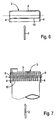
- Fig. 7
- eine schematische Darstellung der Drehlagerung der Abgasklappe am Abgaskanal gemäß Pfeil VII in Fig. 4
- Fig. 8
- eine weitere Seitenansicht eines Abgaskanalendes mit einer Ausführungsform einer Abgasklappe mit mehreren Strömungskörpern in geschlossener Stellung
- Fig. 9
- Prinzipdarstellungen von drei Funktionsstellungen der Abgasklappe sowie die Kurve des Gegendruckverlaufs und die Kurve des Öffnungswinkels aufgetragen über den Massenstrom.
- 1.
- Abgaskanal
- 2.
- Strömungsrichtung
- 3.
- Abgasklappe
- 4.
- Klappenseitenwand
- 5.
- Verschlussplatte
- 6.
- Scharniergelenk
- 7.
- Scharnierbolzen
- 8.
- Lagerauge
- 9.
- Festende
- 10.
- Rückstellfeder
- 11.
- Aussparung
- 12.
- Querrichtung
- 13.
- Freiende
- 14.
- Strömungskörper
- 15.
- Anschlag
- 16.
- Drahtgestrick
- 17.
- Strömungszusatzkörper
Claims (9)
- Abgasklappe (3) zum Verschließen eines Abgaskanals (1)
gekennzeichnetdurch eine vom Abgasstrom unmittelbar angeströmte, den Querschnitt des Abgaskanals (1) zumindest teilweise verschließende Verschlussplatte (5),durch einen neben der Verschlussplatte (5) angeordneten, vom Abgasstrom anströmbaren, als Stellglied für die Abgasklappe (3) wirksamen Strömungskörper (14), unddurch einen Strömungsspalt zwischen Verschlussplatte (5) und Strömungskörper (14). - Abgasklappe nach Anspruch 1,
dadurch gekennzeichnet, dass die Abgasklappe (3) vorzugsweise am Ende eines Kanalabschnitts des Abgaskanals (1) angeordnet ist und gegen die Kraft eines Rückstellelements, insbesondere den Federdruck einer Rückstellfeder (10) schwenkbar gelagert ist. - Abgasklappe nach Anspruch 1 oder Anspruch 2,
gekennzeichnet, durch einen U-förmigen Querschnitt, dessen U-Schenkel jeweils eine Klappenseitenwand (4) bilden und dessen die U-Schenkel verbindendes U-Querjoch die Verschlussplatte (5) ist. - Abgasklappe nach Anspruch 3,
dadurch gekennzeichnet, dass die Klappenseitenwände (4) gabelartig verlängert sind zur zusätzlichen Halterung des Strömungskörpers (14) zwischen sich. - Abgasklappe nach einem oder mehreren der Ansprüche 1 bis 4,
gekennzeichnet durch eine ebene Platte als Strömungskörper (14) mit einer zur Ebene der Verschlussplatte (5) einen Anstellwinkel aufweisenden Strömungskörperebene. - Abgasklappe nach einem der Ansprüche 1 bis 4,
gekennzeichnet durch eine mit einem Anstellwinkel zur Ebene der Verschlussplatte (5) ausgebildete, gewölbte Platte als Strömungskörper (14). - Abgasklappe nach Anspruch 6,
gekennzeichnet durch einen als Tragflügel ausgebildeten Strömungskörper (14). - Abgasklappe nach einem der Ansprüche 1 bis 7,
gekennzeichnet durch mehrere nebeneinander angeordnete Strömungskörper (14). - Abgasklappe nach einem der Ansprüche 1 bis 8,
dadurch gekennzeichnet, dass der oder die Strömungskörper (14) an einem Freiende (13) der Abgasklappe (3) angeordnet sind und dass ein Scharniergelenk (6) und die Rückstellfeder (10) am gegenüberliegenden Festende (9) angeordnet sind.
Applications Claiming Priority (5)
| Application Number | Priority Date | Filing Date | Title |
|---|---|---|---|
| DE10128949 | 2001-06-19 | ||
| DE10128949A DE10128949A1 (de) | 2001-06-19 | 2001-06-19 | Abgasklappe |
| US46324 | 2001-10-19 | ||
| US10/046,324 US6732511B2 (en) | 2001-06-19 | 2001-10-19 | Exhaust flap |
| PCT/EP2002/006027 WO2002103173A1 (de) | 2001-06-19 | 2002-06-01 | Abgasklappe |
Publications (2)
| Publication Number | Publication Date |
|---|---|
| EP1397582A1 EP1397582A1 (de) | 2004-03-17 |
| EP1397582B1 true EP1397582B1 (de) | 2005-08-31 |
Family
ID=26009528
Family Applications (1)
| Application Number | Title | Priority Date | Filing Date |
|---|---|---|---|
| EP02780757A Expired - Lifetime EP1397582B1 (de) | 2001-06-19 | 2002-06-01 | Abgasklappe |
Country Status (3)
| Country | Link |
|---|---|
| EP (1) | EP1397582B1 (de) |
| DE (1) | DE50204096D1 (de) |
| WO (1) | WO2002103173A1 (de) |
Family Cites Families (7)
| Publication number | Priority date | Publication date | Assignee | Title |
|---|---|---|---|---|
| US4162740A (en) * | 1977-09-29 | 1979-07-31 | Jones Clifford W | Valve cover |
| JPS57135217A (en) * | 1981-02-16 | 1982-08-20 | Iseki & Co Ltd | Cap device for muffler |
| US4742766A (en) * | 1986-05-12 | 1988-05-10 | Davison Jerome G | Dynamically balanced exhaust pipe cap |
| JPH0629921U (ja) * | 1992-09-29 | 1994-04-19 | オーエム工業株式会社 | 燃料タンクの逆流防止弁 |
| US5801343A (en) * | 1993-11-09 | 1998-09-01 | Futaba Industrial Co., Ltd. | Muffler for internal combustion engine |
| JPH11193710A (ja) * | 1997-12-26 | 1999-07-21 | Toyota Motor Corp | 内燃機関における消音装置 |
| DE19935711C1 (de) | 1999-07-29 | 2000-12-28 | Zeuna Staerker Kg | Schalldämpfer mit variabler Dämpfungscharakteristik |
-
2002
- 2002-06-01 WO PCT/EP2002/006027 patent/WO2002103173A1/de not_active Ceased
- 2002-06-01 EP EP02780757A patent/EP1397582B1/de not_active Expired - Lifetime
- 2002-06-01 DE DE50204096T patent/DE50204096D1/de not_active Expired - Lifetime
Also Published As
| Publication number | Publication date |
|---|---|
| EP1397582A1 (de) | 2004-03-17 |
| DE50204096D1 (de) | 2005-10-06 |
| WO2002103173A1 (de) | 2002-12-27 |
Similar Documents
| Publication | Publication Date | Title |
|---|---|---|
| DE10128949A1 (de) | Abgasklappe | |
| DE19500475C2 (de) | Absperr- oder Drosselventil mit drehbarer Ventilklappe | |
| DE19935711C1 (de) | Schalldämpfer mit variabler Dämpfungscharakteristik | |
| DE102012101322B4 (de) | Turbolader | |
| EP2458182B1 (de) | Einrichtung zur Beeinflussung von Gas-Volumenströmen, Verfahren zur Steuerung und/oder Regelung eines Abgasstromes oder eines Ladeluftstromes, Abgasstrang und Kraftfahrzeug | |
| EP2317095A1 (de) | Stelleinrichtung für eine Ventilklappe | |
| DE10235528A1 (de) | Abgassystem für eine Brennkraftmaschine | |
| DE102009050182A1 (de) | Abgasturboladergehäuse mit einem verschließbaren Strömungskanal | |
| EP2870350B1 (de) | Rückschlagventilvorrichtung für eine verbrennungskraftmaschine | |
| DE19816840C2 (de) | Brennkraftmaschine mit mehreren, wahlweise zu- und abschaltbaren Abgasturboladern | |
| EP1936151A2 (de) | Verfahren zum Herstellen einer Vorrichtung zur Steuerung des Durchflusses eines gasförmigen oder flüssigen Mediums | |
| DE3737828A1 (de) | Verbrennungsmotor der kolbenbauart | |
| EP1637783B1 (de) | Schnellschluss-Stellventilkombination für eine Dampfturbine | |
| EP0039375A1 (de) | Steuerungseinrichtung in einer gasdynamischen Druckwellenmaschine zur Aufladung von Verbrennungsmotoren | |
| DE102009015184B4 (de) | Klappenventil | |
| EP1445451A2 (de) | Drosselanordnung sowie Abgasanlage mit einer derartigen Drosselanordnung | |
| DE102018006963B4 (de) | Abgasturbolader und Drosselventil zur effizienten Luftbeaufschlagung eines Verdichterrads desselben | |
| DE102011078907A1 (de) | Vervollkommnetes Ventil und Anwendung | |
| DE102016104102A1 (de) | Antrieb für eine Abgasklappe | |
| EP1397582A1 (de) | Abgasklappe | |
| DE102010050171B4 (de) | Ventileinrichtung sowie Aufladeeinrichtung für eine Verbrennungskraftmaschine mit einer solchen Ventileinrichtung | |
| DE10332640B3 (de) | Luftansaugkanalsystem für Verbrennungskraftmaschinen | |
| CH675452A5 (de) | ||
| EP1561996B1 (de) | Absperrvorrichtung für ein Gas führendes Rohr | |
| DE102020107769A1 (de) | Regelungsvorrichtung für einen Abgasführungsabschnitt eines Abgasturbolader und Abgasführungsabschnitt für einen Abgasturbolader |
Legal Events
| Date | Code | Title | Description |
|---|---|---|---|
| PUAI | Public reference made under article 153(3) epc to a published international application that has entered the european phase |
Free format text: ORIGINAL CODE: 0009012 |
|
| 17P | Request for examination filed |
Effective date: 20040102 |
|
| AK | Designated contracting states |
Kind code of ref document: A1 Designated state(s): AT BE CH CY DE DK ES FI FR GB GR IE IT LI LU MC NL PT SE TR |
|
| AX | Request for extension of the european patent |
Extension state: AL LT LV MK RO SI |
|
| RIN1 | Information on inventor provided before grant (corrected) |
Inventor name: LEHRINGER, FRANK, JUERGEN Inventor name: OLEJNICZAK, GERHARD Inventor name: UNBEHAUN, MARTIN Inventor name: ZINTEL, GERHARD |
|
| GRAP | Despatch of communication of intention to grant a patent |
Free format text: ORIGINAL CODE: EPIDOSNIGR1 |
|
| GRAS | Grant fee paid |
Free format text: ORIGINAL CODE: EPIDOSNIGR3 |
|
| GRAA | (expected) grant |
Free format text: ORIGINAL CODE: 0009210 |
|
| RBV | Designated contracting states (corrected) |
Designated state(s): DE FR GB IT |
|
| AK | Designated contracting states |
Kind code of ref document: B1 Designated state(s): DE FR GB IT |
|
| PG25 | Lapsed in a contracting state [announced via postgrant information from national office to epo] |
Ref country code: GB Free format text: LAPSE BECAUSE OF FAILURE TO SUBMIT A TRANSLATION OF THE DESCRIPTION OR TO PAY THE FEE WITHIN THE PRESCRIBED TIME-LIMIT Effective date: 20050831 |
|
| REG | Reference to a national code |
Ref country code: GB Ref legal event code: FG4D Free format text: NOT ENGLISH |
|
| REF | Corresponds to: |
Ref document number: 50204096 Country of ref document: DE Date of ref document: 20051006 Kind code of ref document: P |
|
| GBV | Gb: ep patent (uk) treated as always having been void in accordance with gb section 77(7)/1977 [no translation filed] |
Effective date: 20050831 |
|
| ET | Fr: translation filed | ||
| PGFP | Annual fee paid to national office [announced via postgrant information from national office to epo] |
Ref country code: IT Payment date: 20060630 Year of fee payment: 5 |
|
| PLBE | No opposition filed within time limit |
Free format text: ORIGINAL CODE: 0009261 |
|
| STAA | Information on the status of an ep patent application or granted ep patent |
Free format text: STATUS: NO OPPOSITION FILED WITHIN TIME LIMIT |
|
| 26N | No opposition filed |
Effective date: 20060601 |
|
| PG25 | Lapsed in a contracting state [announced via postgrant information from national office to epo] |
Ref country code: IT Free format text: LAPSE BECAUSE OF NON-PAYMENT OF DUE FEES Effective date: 20070601 |
|
| REG | Reference to a national code |
Ref country code: DE Ref legal event code: R082 Ref document number: 50204096 Country of ref document: DE Representative=s name: MEISSNER BOLTE & PARTNER GBR, DE Ref country code: DE Ref legal event code: R082 Ref document number: 50204096 Country of ref document: DE Representative=s name: MEISSNER BOLTE PATENTANWAELTE RECHTSANWAELTE P, DE |
|
| REG | Reference to a national code |
Ref country code: DE Ref legal event code: R082 Ref document number: 50204096 Country of ref document: DE Representative=s name: MEISSNER BOLTE PATENTANWAELTE RECHTSANWAELTE P, DE |
|
| REG | Reference to a national code |
Ref country code: FR Ref legal event code: PLFP Year of fee payment: 15 |
|
| REG | Reference to a national code |
Ref country code: FR Ref legal event code: PLFP Year of fee payment: 16 |
|
| REG | Reference to a national code |
Ref country code: FR Ref legal event code: PLFP Year of fee payment: 17 |
|
| PGFP | Annual fee paid to national office [announced via postgrant information from national office to epo] |
Ref country code: DE Payment date: 20180627 Year of fee payment: 17 |
|
| REG | Reference to a national code |
Ref country code: DE Ref legal event code: R119 Ref document number: 50204096 Country of ref document: DE |
|
| PG25 | Lapsed in a contracting state [announced via postgrant information from national office to epo] |
Ref country code: DE Free format text: LAPSE BECAUSE OF NON-PAYMENT OF DUE FEES Effective date: 20200101 |
|
| PGFP | Annual fee paid to national office [announced via postgrant information from national office to epo] |
Ref country code: FR Payment date: 20210519 Year of fee payment: 20 |