EP1396954A1 - Error-correction multiplexing apparatus; error-correction demultiplexing apparatus; optical transmission system using them; and error-correction multiplexing transmission method - Google Patents
Error-correction multiplexing apparatus; error-correction demultiplexing apparatus; optical transmission system using them; and error-correction multiplexing transmission method Download PDFInfo
- Publication number
- EP1396954A1 EP1396954A1 EP02738668A EP02738668A EP1396954A1 EP 1396954 A1 EP1396954 A1 EP 1396954A1 EP 02738668 A EP02738668 A EP 02738668A EP 02738668 A EP02738668 A EP 02738668A EP 1396954 A1 EP1396954 A1 EP 1396954A1
- Authority
- EP
- European Patent Office
- Prior art keywords
- data stream
- parallel data
- correcting code
- error
- error correction
- Prior art date
- Legal status (The legal status is an assumption and is not a legal conclusion. Google has not performed a legal analysis and makes no representation as to the accuracy of the status listed.)
- Withdrawn
Links
Images













Classifications
-
- H—ELECTRICITY
- H04—ELECTRIC COMMUNICATION TECHNIQUE
- H04L—TRANSMISSION OF DIGITAL INFORMATION, e.g. TELEGRAPHIC COMMUNICATION
- H04L1/00—Arrangements for detecting or preventing errors in the information received
- H04L1/004—Arrangements for detecting or preventing errors in the information received by using forward error control
- H04L1/0045—Arrangements at the receiver end
- H04L1/0047—Decoding adapted to other signal detection operation
- H04L1/005—Iterative decoding, including iteration between signal detection and decoding operation
-
- H—ELECTRICITY
- H03—ELECTRONIC CIRCUITRY
- H03M—CODING; DECODING; CODE CONVERSION IN GENERAL
- H03M13/00—Coding, decoding or code conversion, for error detection or error correction; Coding theory basic assumptions; Coding bounds; Error probability evaluation methods; Channel models; Simulation or testing of codes
- H03M13/27—Coding, decoding or code conversion, for error detection or error correction; Coding theory basic assumptions; Coding bounds; Error probability evaluation methods; Channel models; Simulation or testing of codes using interleaving techniques
- H03M13/2703—Coding, decoding or code conversion, for error detection or error correction; Coding theory basic assumptions; Coding bounds; Error probability evaluation methods; Channel models; Simulation or testing of codes using interleaving techniques the interleaver involving at least two directions
- H03M13/2721—Coding, decoding or code conversion, for error detection or error correction; Coding theory basic assumptions; Coding bounds; Error probability evaluation methods; Channel models; Simulation or testing of codes using interleaving techniques the interleaver involving at least two directions the interleaver involves a diagonal direction, e.g. by using an interleaving matrix with read-out in a diagonal direction
-
- H—ELECTRICITY
- H03—ELECTRONIC CIRCUITRY
- H03M—CODING; DECODING; CODE CONVERSION IN GENERAL
- H03M13/00—Coding, decoding or code conversion, for error detection or error correction; Coding theory basic assumptions; Coding bounds; Error probability evaluation methods; Channel models; Simulation or testing of codes
- H03M13/29—Coding, decoding or code conversion, for error detection or error correction; Coding theory basic assumptions; Coding bounds; Error probability evaluation methods; Channel models; Simulation or testing of codes combining two or more codes or code structures, e.g. product codes, generalised product codes, concatenated codes, inner and outer codes
- H03M13/2906—Coding, decoding or code conversion, for error detection or error correction; Coding theory basic assumptions; Coding bounds; Error probability evaluation methods; Channel models; Simulation or testing of codes combining two or more codes or code structures, e.g. product codes, generalised product codes, concatenated codes, inner and outer codes using block codes
- H03M13/2921—Coding, decoding or code conversion, for error detection or error correction; Coding theory basic assumptions; Coding bounds; Error probability evaluation methods; Channel models; Simulation or testing of codes combining two or more codes or code structures, e.g. product codes, generalised product codes, concatenated codes, inner and outer codes using block codes wherein error correction coding involves a diagonal direction
-
- H—ELECTRICITY
- H03—ELECTRONIC CIRCUITRY
- H03M—CODING; DECODING; CODE CONVERSION IN GENERAL
- H03M13/00—Coding, decoding or code conversion, for error detection or error correction; Coding theory basic assumptions; Coding bounds; Error probability evaluation methods; Channel models; Simulation or testing of codes
- H03M13/65—Purpose and implementation aspects
- H03M13/6561—Parallelized implementations
-
- H—ELECTRICITY
- H04—ELECTRIC COMMUNICATION TECHNIQUE
- H04J—MULTIPLEX COMMUNICATION
- H04J3/00—Time-division multiplex systems
- H04J3/16—Time-division multiplex systems in which the time allocation to individual channels within a transmission cycle is variable, e.g. to accommodate varying complexity of signals, to vary number of channels transmitted
- H04J3/1605—Fixed allocated frame structures
- H04J3/1611—Synchronous digital hierarchy [SDH] or SONET
-
- H—ELECTRICITY
- H04—ELECTRIC COMMUNICATION TECHNIQUE
- H04L—TRANSMISSION OF DIGITAL INFORMATION, e.g. TELEGRAPHIC COMMUNICATION
- H04L1/00—Arrangements for detecting or preventing errors in the information received
- H04L1/004—Arrangements for detecting or preventing errors in the information received by using forward error control
-
- H—ELECTRICITY
- H04—ELECTRIC COMMUNICATION TECHNIQUE
- H04L—TRANSMISSION OF DIGITAL INFORMATION, e.g. TELEGRAPHIC COMMUNICATION
- H04L1/00—Arrangements for detecting or preventing errors in the information received
- H04L1/004—Arrangements for detecting or preventing errors in the information received by using forward error control
- H04L1/0056—Systems characterized by the type of code used
- H04L1/0057—Block codes
-
- H—ELECTRICITY
- H04—ELECTRIC COMMUNICATION TECHNIQUE
- H04L—TRANSMISSION OF DIGITAL INFORMATION, e.g. TELEGRAPHIC COMMUNICATION
- H04L1/00—Arrangements for detecting or preventing errors in the information received
- H04L1/004—Arrangements for detecting or preventing errors in the information received by using forward error control
- H04L1/0056—Systems characterized by the type of code used
- H04L1/0064—Concatenated codes
- H04L1/0066—Parallel concatenated codes
-
- H—ELECTRICITY
- H04—ELECTRIC COMMUNICATION TECHNIQUE
- H04L—TRANSMISSION OF DIGITAL INFORMATION, e.g. TELEGRAPHIC COMMUNICATION
- H04L1/00—Arrangements for detecting or preventing errors in the information received
- H04L1/004—Arrangements for detecting or preventing errors in the information received by using forward error control
- H04L1/0056—Systems characterized by the type of code used
- H04L1/0071—Use of interleaving
-
- H—ELECTRICITY
- H03—ELECTRONIC CIRCUITRY
- H03M—CODING; DECODING; CODE CONVERSION IN GENERAL
- H03M13/00—Coding, decoding or code conversion, for error detection or error correction; Coding theory basic assumptions; Coding bounds; Error probability evaluation methods; Channel models; Simulation or testing of codes
- H03M13/03—Error detection or forward error correction by redundancy in data representation, i.e. code words containing more digits than the source words
- H03M13/05—Error detection or forward error correction by redundancy in data representation, i.e. code words containing more digits than the source words using block codes, i.e. a predetermined number of check bits joined to a predetermined number of information bits
- H03M13/13—Linear codes
- H03M13/15—Cyclic codes, i.e. cyclic shifts of codewords produce other codewords, e.g. codes defined by a generator polynomial, Bose-Chaudhuri-Hocquenghem [BCH] codes
-
- H—ELECTRICITY
- H03—ELECTRONIC CIRCUITRY
- H03M—CODING; DECODING; CODE CONVERSION IN GENERAL
- H03M13/00—Coding, decoding or code conversion, for error detection or error correction; Coding theory basic assumptions; Coding bounds; Error probability evaluation methods; Channel models; Simulation or testing of codes
- H03M13/03—Error detection or forward error correction by redundancy in data representation, i.e. code words containing more digits than the source words
- H03M13/05—Error detection or forward error correction by redundancy in data representation, i.e. code words containing more digits than the source words using block codes, i.e. a predetermined number of check bits joined to a predetermined number of information bits
- H03M13/13—Linear codes
- H03M13/15—Cyclic codes, i.e. cyclic shifts of codewords produce other codewords, e.g. codes defined by a generator polynomial, Bose-Chaudhuri-Hocquenghem [BCH] codes
- H03M13/151—Cyclic codes, i.e. cyclic shifts of codewords produce other codewords, e.g. codes defined by a generator polynomial, Bose-Chaudhuri-Hocquenghem [BCH] codes using error location or error correction polynomials
- H03M13/1515—Reed-Solomon codes
-
- H—ELECTRICITY
- H04—ELECTRIC COMMUNICATION TECHNIQUE
- H04J—MULTIPLEX COMMUNICATION
- H04J2203/00—Aspects of optical multiplex systems other than those covered by H04J14/05 and H04J14/07
- H04J2203/0001—Provisions for broadband connections in integrated services digital network using frames of the Optical Transport Network [OTN] or using synchronous transfer mode [STM], e.g. SONET, SDH
- H04J2203/0089—Multiplexing, e.g. coding, scrambling, SONET
Definitions
- Error correction multiplexer Error correction multiplexer, error correction demultiplexer, optical transmission system employing the error correction multiplexer and the error correction demultiplexer, and method of error correction multiplexing transmission
- the present invention relates to an error correction multiplexer, an error correction demultiplexer, an optical transmission system employing the error correction multiplexer and the error correction demultiplexer, and a method of error correction multiplexing transmission that corrects bit errors caused by deterioration of signal-to-noise ratio, based on forward error correction (FEC), and to implement long-haul, high-capacity transmission.
- FEC forward error correction
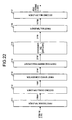
- Fig. 22 is a block diagram of an FEC multiplexer at a transmitting end that employs the FEC method recommended by ITU-T G.975.
- Fig. 23 is a block diagram of an FEC demultiplexer at a receiving end that employs the FEC method.
- a first demultiplexer 211 receives and demultiplexes an STM-16 data of 2.5 Gbps into 16 parallel data stream of 156 Mbps and outputs the 16 parallel data stream to a second demultiplexer 212.
- the second demultiplexer 212 receives and further demultiplexes the 16 parallel data stream into 128 parallel data stream of 19 Mbps, and outputs the 128 parallel data stream to a first rate converter 213.
- the first rate converter 213 receives the 128 parallel data stream of 19 Mbps and adds a redundant data area to the data stream. The first rate converter 213 then rate-converts the 128 parallel data stream of 19 Mbps into 128 parallel data stream of 21 Mbps and outputs it to an overhead inserting circuit 214.
- the overhead inserting circuit 214 inserts an overhead (OH) bit such as a frame synchronization data that is necessary for the maintenance and the operation of the optical system, and outputs the overhead (OH) data to an encoder 215.
- OH overhead
- the encoder 215 carries out error correction encoding by means of Reed Solomon (255,239) codes and outputs the encoded data to a first multiplexer 216.
- the first multiplexer 216 multiplexes the 128 parallel data stream into 16 parallel data stream of 167 Mbps and outputs the 16 parallel data stream to a second multiplexer 217.
- the second multiplexer 217 receives the 16 parallel data stream and further multiplexes it to a FEC frame of 2.66 Gbps.
- the second multiplexer 217 then converts the FEC frame of 2.66 Gbps into an optical signal via an optical transmitter and outputs the optical signal to an optical transmission channel.
- the optical signal from the optical transmission channel is converted into an electrical signal by an optical receiver and output the electrical signal to a third demultiplexer 221.
- the third demultiplexer 221 receives and demultiplexes the FEC frame of 2.66 Gbps into 16 parallel data stream of 167 Mbps, and outputs the 16 parallel data stream of 167 Mbps to a fourth demultiplexer 222.
- the fourth demultiplexing 222 receives the 16 parallel data stream, further demultiplexes it into the 128 parallel data stream of 21 Mbps, and outputs the 128 parallel data stream of 21 Mbps to a frame synchronization circuit 223.
- the frame synchronization circuit 223 detects the header position of the FEC frame based on the frame synchronization data included in an overhead data area and outputs frame-synchronized data to a decoder 224.
- the decoder 224 detects and corrects bit errors by means of the Reed Solomon (255,239) codes and outputs the corrected data to an overhead separating circuit 225.
- the overhead separating circuit 225 separates the overhead data area.
- a second rate converter 226 removes the redundant data area in which the error correction codes are stored, converts the remaining data into the 128 parallel data stream of 19 Mbps, and outputs it to a third multiplexer 227.
- the third multiplexer 227 receives and multiplexes the 128 parallel data stream of 19 Mbps to the 16 parallel data stream of 156 Mbps, and outputs the 16 parallel data stream of 156 Mbps to a fourth multiplexer 228.
- the fourth multiplexer 228 receives and multiplexes the 16 parallel data stream of 156 Mbps and outputs it as the STM-16 data stream of 2.5 Gbps.
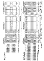
- the FEC frame is composed of subframes 1 through 128 that include one column of the overhead bit, 238 columns of the STM-16 data, and 16 columns of a Reed Solomon (255,239) redundant data.
- the error correction encoding is carried out after every eighth subframe.
- the error correction encoding is carried out for the overhead bit and the STM-16 data, and the Reed Solomon (255,239) redundant data is stored in columns R0-0 through R0-15.
- the transmission rate in the FEC frame increases 15/14 times with respect to the original rate of the STM-16. Hence, the transmission rate of the FEC frame becomes 2.66 Gbps. In this way, the bit errors can be corrected by adding the FEC frame and a high quality service can be offered in an optical transmission system. Hence, an optical transmission system that facilitates transmission of high capacity of signals over long distances can be built.
- the transmission rate of the FEC frame becomes 127/111 times to 2.89 Gbps with respect to the rate of 2.5 Gbps of the STM-16 data, resulting in more deterioration of the optical transmission characteristics.
- the code length is reduced, an optical transmission system that maintains a certain quality and facilitates transmission of high capacity of signals over a long distance cannot be built.
- a demultiplexer receives and demultiplexes a serial data stream into a parallel data stream.
- a first encoder carries out error correction encoding in a first direction of a matrix constituted by the parallel data stream and adds a first error-correcting code to the parallel data stream.
- a second encoder carries out error correction encoding in a second direction of the matrix constituted by the parallel data stream and adds a second error-correcting code to the parallel data stream.
- a multiplexer multiplexes the parallel data stream encoded by the first encoder and the second encoder and outputs a serial data stream. The error-correcting codes in the two directions are independent of each other because of the serial data stream, and the bit errors are distributed.
- the demultiplexer demultiplexes the received serial data stream into n parallel data stream (where n is a positive integer) and demultiplexes the n parallel data stream further into (n ⁇ (m-i)) parallel data stream (where m and i are positive integers and m is greater than i).
- the first encoder and the second encoder output the (n ⁇ (m-i)) parallel data stream as (n ⁇ m) parallel data stream to the multiplexer.
- the multiplexer multiplexes the received (nxm) parallel data stream into n parallel data stream and outputs the n parallel data stream as a serial data stream.
- the demultiplexer demultiplexes the received serial data stream into n parallel data stream (where n is a positive integer) and demultiplexes the n parallel data stream further into (n ⁇ m) parallel data stream (where m is a positive integer).
- the first encoder and the second encoder outputs the received (n ⁇ m) parallel data stream as (n ⁇ (m+i)) parallel data stream (where m and i are positive integers and m is greater than i) to the multiplexer.
- the multiplexer multiplexes the received (n ⁇ (m+i)) parallel data stream into n parallel data stream and outputs the n parallel data stream as a serial data stream.
- the demultiplexer demultiplexes the received serial data stream into n parallel data stream (where n is a positive integer) and demultiplexes the n parallel data stream further into (n ⁇ m) parallel data stream (where m is a positive integer).
- the first encoder and the second encoder outputs the received (n ⁇ m) parallel data stream as (n ⁇ (m+i)) parallel data stream (where m and i are positive integers and m is greater than i) to the multiplexer.
- the multiplexer multiplexes the received (n ⁇ (m+i)) parallel data stream into n parallel data stream and outputs the n parallel data stream as a serial data stream.
- the first encoder carries out en error correction encoding in the column direction of the matrix constituted by the parallel data stream and adds the resulting first error-correcting code to the parallel data stream.
- the second encoder carries out error correction encoding and adds the resulting second error-correcting code to the parallel data stream.
- the error correction encoding by the first encoder is independent of the error correction encoding by the second encoder.
- the first encoder adds the first error correcting code to a specific row at the end of columns of the parallel data stream and the second encoder adds the second error correcting code to a specific column at the end of the rows of the parallel data stream.
- the demultiplexer adds to the parallel data stream an area in which the first error-correcting code generated by the first encoder is stored.
- the areas for storing the error correcting codes are created when there is flexibility during low rate.
- the first encoder carries out error correction encoding in a diagonal direction of the matrix constituted by the parallel data stream and adds the resulting error-correcting code to the parallel data stream.
- the second encoder carries out error correction encoding in the row direction of the matrix constituted by the parallel data stream and adds the resulting error-correcting code to the parallel data stream.
- the directions of the error correction encoding by the first encoder and the second encoder are therefore not orthogonal.
- the first encoder adds the first error-correcting code to a specific row at the end of the columns of the parallel data stream.
- the second encoder adds the second error-correcting code adjacent to error-correcting code added by the first encoder.
- the second encoder carries out error correction encoding for the parallel data stream which includes the first error-correcting code added by the first encoder and adds the resulting second error-correcting code to the parallel data stream. In this way, the second encoder also corrects the errors in the error-correcting code generated by the first encoder.
- the first error-correcting code added by the first encoder and the second error-correcting code added by the second encoder differ in their coding systems.
- the first error-correcting code added by the first encoder and the second error-correcting code added by the second encoder are block codes. Consequently, the capacity of the error-correcting codes can be fixed.
- the first error-correcting code added by the first encoder and the second error-correcting code added by the second encoder are calculated in the same block coding system, and differ in the coding conditions.
- the parallel data stream includes a data area, an overhead data area in the column direction that is added to the beginning of the row direction of the data area, and a fixed stuff area, which absorbs the difference arising from the parallel data stream matrix.
- the quantity of the overhead bits is increased by storing the overhead bits in the fixed stuff area.
- a demultiplexer demultiplexes into parallel data stream a multiplexed serial data stream of plural error-correcting codes generated by error correction encoding in two different directions of a parallel data stream.
- a decoder gradually decodes the parallel data stream by the plural error-correcting codes and outputs a decoded parallel data stream.
- a multiplexer multiplexes the parallel data stream decoded by the decoder and outputs a serial data stream. The decoding is carried out by the decoder using the independent error-correcting codes.
- the demultiplexer demultiplexes a received serial data stream into n parallel data stream (where n is a positive integer), and further into (n ⁇ m) parallel data stream (where m is a positive integer).
- the decoder converts the received (n ⁇ m) parallel data stream into (n ⁇ (m-i)) parallel data stream (where i is a positive integer, and m is greater than i), and outputs the (n ⁇ (m-i)) parallel data stream to the multiplexer.
- the multiplexer multiplexes the (n ⁇ (m-i)) parallel data stream into n parallel data stream and converts and outputs the n parallel data stream as a serial data stream.
- the demultiplexer demultiplexes the received serial data stream into n parallel data stream (where n is a positive integer) and further into (n ⁇ (m+i)) parallel data stream (where m and i are positive integer, and m is greater than i).
- the decoder converts the received (n ⁇ (m+i)) parallel data stream into (nlm) parallel data stream and outputs the (n ⁇ m) parallel data stream to the multiplexer.
- the multiplexer multiplexes the received (n ⁇ m) parallel data stream into n parallel data stream and converts and outputs the n parallel data stream as a serial data stream.
- a first decoder extracts a first error-correcting code from the parallel data stream received from the demultiplexer, carries out error correction decoding, based on the extracted error-correcting code, in a first direction of the matrix constituted by the parallel data stream, and outputs the result of the decoding.
- a second decoder extracts a second error-correcting code from the parallel data stream received from the demultiplexer, carries out error correction decoding, based on the extracted error-correcting code, in a second direction of the matrix constituted by the parallel data stream, and outputs the decoding result.
- the second decoder carries out error correction decoding using the decoding result of the first decoder. In this way, the remaining bit errors are reliably corrected.
- the demultiplexer demultiplexes a parallel bit stream that is quantized into plural bits by a soft decision process.
- the first decoder and the second decoder carry out soft decision decoding, wherein the second decoder uses the decoding result of the first decoder.
- the demultiplexer demultiplexes the parallel data stream that is quantized into plural bits by a soft decision process.
- the first decoder and the second decoder which are connected in series in multiple stages, carry out an iterative soft decision decoding.
- the second decoder decodes data by iterative soft decision decoding in which the result is repeatedly input into the first decoder a predetermined number of times.
- An optical transmission system comprises a first optical receiver that receives and converts an optical signal to an electrical signal, an error correction multiplexer according to any one of the inventions described above that multiplexes a serial data stream output from the first optical receiver, a first optical transmitter that converts the electrical signal output from the error correction multiplexer to the optical signal and transmits the optical signal to an optical transmission channel, a second optical receiver that converts the optical signal output from the optical transmission channel into an electrical signal, an error correction demultiplexer according to any one of the inventions described above that demultiplexes a parallel data stream output from the second optical receiver, and a second optical transmitter that converts the electrical signal output from the error correction demultiplexer into an optical signal.
- a first optical receiver converts received an optical signal into an electrical signals. Any one of the error correction multiplexers according to the present invention processes the serial data stream output from the first optical receiver.
- a first optical transmitter converts into an optical signal the electrical signal output from the error correction multiplexer and transmits the optical signal to the optical transmission channel.
- a second optical receiver converts the optical signal received from the optical transmission channel into an electrical signal. Any one of the error correction demultiplexers according to the present invention processes the electrical signals output from the second optical receiver.
- a second optical transmitter converts the electrical signal output from the error correction demultiplexer into an optical signal.
- the second optical receiver carries out a soft decision process and carries out a soft decision decoding based on the soft decision process.
- a demultiplexing step received serial data stream is demultiplexed into parallel data stream.
- error correction encoding is carried out in a first direction of the matrix constituted by the parallel data stream.
- error correction encoding is carried out in a second direction of the matrix constituted by the parallel data stream.
- the resulting first and second error-correcting codes are added to the parallel data stream.
- the encoded parallel data stream, to which the plural error-correcting codes are added in the first and second encoding steps is multiplexed and output as a serial data stream.
- the received serial data stream is demultiplexed into n parallel data stream (where n is a positive integer) and further into (n ⁇ (m-i)) parallel data stream (where m and i are positive integers, and m is greater than i).
- the received (n ⁇ (m-i)) parallel data stream is converted and output as (n ⁇ m) parallel data stream.
- the (n ⁇ m) parallel data stream is multiplexed into n parallel data stream and output as a serial data stream.
- the received serial data stream is demultiplexed into n parallel data stream (where n is a positive integer) and further into (n ⁇ m) parallel data stream (where m is a positive integer).
- the received (n ⁇ m) parallel data stream is converted and output as (n ⁇ (m+1)) parallel data stream (where i is a positive integer, and m is greater than i).
- the (n ⁇ (m+i)) parallel data stream is multiplexed into n parallel data stream and output as a serial data stream.
- an error correction encoding is carried out in the column direction of the matrix formed by the parallel data stream and the resulting error-correcting code is added to the parallel data stream.
- an error correction encoding is carried out in the row direction of the matrix formed by the parallel data stream, and the resulting error-correcting code is added to the parallel data stream.
- the error-correcting code generated in the first encoding step is independent of the error-correcting code generated in the second encoding step.
- a first error-correcting code is added to a specific row at the end of the columns of the parallel data stream.
- a second error-correcting code is added to a specific column at the end of the rows of the parallel data stream.
- the first encoding step error correction encoding is carried out a diagonal direction of the matrix constituted by the parallel data stream and the resulting error-correcting code is added to the parallel data stream.
- error correction encoding is carried out in the row direction of the matrix constituted by the parallel data stream and the resulting error-correcting code is added to the parallel data stream.
- the directions of the error correction encoding by the first encoder and the second encoder are therefore not orthogonal.
- the first error-correcting code is added to a specific row at the end of the columns of the parallel data stream.
- the second error-correcting code is added adjacent to the error-correcting code added by the first encoder.
- the second encoding step error correction encoding is carried out for the parallel data stream which includes the first error-correcting code added by the first encoder and the resulting second error-correcting code to is added to the parallel data stream.
- error correction encoding is carried out for the parallel data stream which includes the first error-correcting code added by the first encoder and the resulting second error-correcting code to is added to the parallel data stream.
- the first error-correcting code added in the first encoding step and the second error-correcting code added in the second encoding step differ in their coding systems.
- the first error-correcting coded added in the first encoding step and the second error-correcting code added in the second encoding step are block codes. Consequently, the capacity of the error-correcting codes can be fixed.
- the first error-correcting code added in the first encoding step and the second error-correcting code added in the second encoding step are calculated in the same block coding system, and differ in the coding conditions.
- the quantity of the overhead bits is increased by storing the overhead bits in the fixed stuff area.
- the serial data stream created in the multiplexing step is demultiplexed into parallel data stream.
- a first error-corrected code is extracted from the parallel data stream created in the demultiplexing step at the receiving end and, based on the extracted error-correcting code, error correction decoding is carried out in a first direction of the matrix formed by the parallel data stream, and the decoding result is output.
- a second error-correcting code is extracted from the parallel data stream created in the demultiplexing step at the receiving end and, based on the extracted error-correcting code, error correction decoding is carried out in a second direction of the matrix formed by the parallel data stream, and the decoding result is output.
- the parallel data stream is multiplexed and output as a serial data stream. In this way, independent error-correcting codes are used during decoding.
- error correction decoding is carried out using the decoding result of the first decoder. In this way, the remaining bit errors are reliably corrected.
- a parallel bit stream is quantized into plural bits by a soft decision process.
- soft decision decoding wherein the decoding result of the first decoding step is used in the second decoding step, is carried out.
- a parallel bit stream is quantized into plural bits by a soft decision process.
- iterative soft decision process is carried out, using the decoding result of the first decoder, for a predetermined number of times.
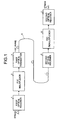
- Fig. 1 is a block diagram of an optical transmission system according to a first embodiment of the present invention
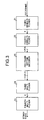
- Fig. 2 is a block diagram of the FEC multiplexer shown in Fig. 1
- Fig. 3 is a block diagram of the FEC demultiplexer shown in Fig. 1
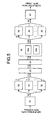
- Fig. 4 (a) and (b) illustrate a process of error correction encoding by means of the FEC multiplexer shown in Fig. 2
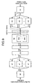
- Fig. 5 is a detailed block diagram of the FEC multiplexer shown in Fig. 1
- Fig. 6 is a detailed block diagram of the FEC demultiplexer shown in Fig. 1
- Fig. 7 is a block diagram of an optical transmission system according to a second embodiment of the present invention
- FIG. 8 is a block diagram of the FEC demultiplexer shown in Fig. 7;
- Fig. 9 is a detailed block diagram of the FEC demultiplexer shown in Fig. 7;
- Fig. 10 is a block diagram of a FEC multiplexer of an optical transmission system according to a third embodiment of the present invention;
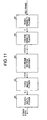
- Fig. 11 is a block diagram of a FEC demultiplexer of the optical transmission system according to the third embodiment of the present invention;
- Fig. 12 is a detailed block diagram of the FEC multiplexer shown in Fig. 10;
- Fig. 13 is a block diagram of the FEC demultiplexer shown in Fig. 11;
- Fig. 14 is a block diagram of an optical transmission system according to a fourth embodiment of the present invention;
- FIG. 15 is a block diagram FEC demultiplexer shown in Fig. 14;
- Fig. 16 is a detailed block diagram of the specific detailed structure of the FEC demultiplexer shown in Fig. 14;
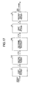
- Fig. 17 is a block diagram of a FEC multiplexer of an optical transmission system according to a sixth embodiment of the present invention;
- Fig. 18 is a block diagram of a FEC demultiplexer of the optical transmission system according to the sixth embodiment of the present invention;
- Fig. 19 (a) and (b) illustrate a process of error correction encoding by means of the FEC multiplexer shown in Fig. 17;
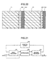
- Fig. 20 illustrates an example of the process of error correction encoding carried out with respect to a multiframe by means of the FEC multiplexer shown in Fig.
- Fig. 21 is a block diagram that illustrates an example of an outline structure of a process of error correction encoding in a FEC multiplexer according to a seventh embodiment of the present invention
- Fig. 22 is a block diagram of a FEC multiplexer according to a conventional optical transmission system
- Fig. 23 is a block diagram of a FEC demultiplexer according to the conventional optical transmission system
- Fig. 24A and Fig. 24B illustrate a frame structure of a FEC frame.
- Fig. 1 is a block diagram of the optical transmission system according to a first embodiment of the present invention.
- a first optical receiver 1 receives a STM-64 optical signal, converts the optical signal into an electrical signal, and outputs the electrical signal to a FEC multiplexer 2.
- the FEC multiplexer 2 multiplexes the electrical signal received from the first optical receiver 1, inserts an overhead (OH) bit, calculates and generates error-correcting codes, etc., multiplexes the error-correcting codes, creates a FEC frame that includes the multiplexed error-correcting codes, and outputs the FEC frame to a first optical transmitter 3.
- the first optical transmitter 3 converts the electric signal of the FEC frame received from the FEC multiplexer 2 into an optical signal and outputs this optical signal to an optical transmission channel 4 that comprises optical fibers.
- a second optical receiver 5 receives the optical signal from the optical transmission channel 4, converts the optical signal to an electrical signal, and outputs the electrical signal to a FEC demultiplexer 6.
- the FEC demultiplexer 6 receives the FEC frame, determines the frame synchronization of the FEC frame, decodes the error-correcting codes based on the added error-correcting codes, separates the added overhead bit, again multiplexes the electrical signal, and outputs the multiplexed electrical signal to a second optical receiver 7.
- the second optical receiver 7 receives and converts the electrical signal into an optical signal, and outputs the converted optical signal as the STM-64 optical signal.
- Transmitting a large amount of optical signals over long distances may give rise to deterioration of signal-to-noise ratio in the optical transmission channel 4 and cause numerous bit errors in the FEC frame output from the second optical receiver 5. These bit errors are corrected by the FEC demultiplexer 6. Consequently, the bit error rate of the STM-64 optical signal can be considerably improved and a transmission service of a prescribed quality can be maintained.
- Fig. 2 is a block diagram of the FEC multiplexer 2 shown in Fig. 1.
- a first demultiplexer 11 receives the STM-64 (of 9.95 Gbps) electrical signal, which is a serial data stream, from the first optical receiver 1, demultiplexes the serial data stream into n parallel data stream(where n is positive integer), and outputs the n parallel data stream to a second demultiplexer 12.
- STM-64 of 9.95 Gbps
- the second demultiplexer 12 receives the n parallel data stream, demultiplexes them into (n ⁇ (m-i)) parallel data stream (where m and i are positive integers and m is greater than i), and outputs the (n ⁇ (m-i)) parallel data stream to a FEC frame generating encoder 13.
- the FEC frame generating encoder 13 receives the (n ⁇ (m-i)) parallel data stream, creates (n ⁇ m) parallel data stream by storing the overhead bit, creating a redundant data area, and storing in the redundant data area the error-correcting codes generated by error correction encoding.
- the FEC frame generating encoder then outputs the (n ⁇ m) parallel data stream to a first multiplexer 14.
- the first multiplexer 14 receives the (n ⁇ m) parallel data stream, multiplexes them into n parallel data stream, and outputs the n parallel data stream to a second multiplexer 15.
- the second multiplexer 15 receives the n parallel data stream, multiplexes and converts it into a serial data stream, and outputs this serial data stream as a FEC frame to the first optical transmitter 3.
- Fig. 3 is a block diagram of the FEC demultiplexer 6 shown in Fig. 1.
- a third demultiplexer 21 receives the FEC frame from the second optical transmitter 5, demultiplexes it into n parallel data stream, and outputs the n parallel data stream to a fourth demultiplexer 22.
- the fourth demultiplexer 22 receives the n parallel data stream, demultiplexes the n parallel data stream into (n ⁇ m) parallel data stream, and outputs the (n ⁇ m) parallel data stream to a FEC frame bottom decoder 23.
- the FEC frame bottom decoder 23 receives the (n ⁇ m) parallel data stream from the fourth demultiplexer 22, determines the frame synchronization, carries out processes such as overhead bit extraction, error decoding based on error encoding, etc., finally creates (n ⁇ (m-i)) parallel data stream, and outputs the (n ⁇ (m-i)) parallel data stream to a third multiplexer 24.
- the third multiplexer 24 receives the (n ⁇ (m-i)) parallel data stream, multiplexes and converts it into n parallel data stream, and outputs it to a fourth multiplexer 25.
- the fourth multiplexer 25 receives the n parallel data stream, multiplexes and converts it into a serial data stream, and outputs the serial data stream as a STM-64 serial data stream (electrical signal) to the second optical receiver 7.
- Fig. 4 (a) and (b) are schematic diagrams that illustrate the error correction encoding process of the FEC frame generating encoder 13 shown in Fig. 2.
- the STM-64 data is stored in a data area E1.
- An overhead data area E2 is disposed in the column before the data area E1.
- Overhead information related to maintenance and operation of the network, of which the optical transmission system is a part, is stored in the overhead data area E2.
- a fixed stuff area E3 is provided for absorbing the difference between code length of the (n ⁇ (m-i)) parallel data stream and the code length n1 in the direction of the column.
- the data area E1, the overhead data area 2, and the fixed stuff area E3 form a matrix of k2 ⁇ k1.
- An error-correcting code in the column direction and having a code length n1, a data length k1, and a redundant bit length r1, is placed in the row direction k2 in a redundant data area E5 (Fig. 4 (a)).
- an error-correcting code in the row direction and having a code length n2, a data length k2, and a redundant bit length r2 is placed in the column direction n1 in an area E4 (Fig. 4 (b)).
- the error-correcting codes placed in the redundant data areas E4 and E5 are processed in directions that are mutually orthogonal and each error-correcting code is independent of the other.
- an error correction in the column direction can be carried out using the error correction result in the row direction.
- an error correction in the row direction can be carried out using the error correction result in the column direction. In this way, a superior error correction capability can be achieved.
- Fig. 5 is a detailed block diagram of the FEC multiplexer 2 shown in Fig. 1.
- Fig. 6 is a detailed block diagram of the FEC demultiplexer 6 shown in Fig. 1.
- a first 1 to 16 serial-parallel converter 31 demultiplexes a STM-64 serial data stream (of 9.95 Gbps) into 16 parallel data stream of 622 Mbps and outputs each 16 parallel data stream to a corresponding 1 to 7 serial-parallel converter 32 placed next.
- the first rate converter 33 receives the 112 parallel data stream of 89 Mbps, adds to the 112 parallel data stream the overhead data area E2 and the redundant data area E4, and outputs the 112 parallel data stream to a overhead inserting circuit 34 as 112 parallel data stream of 102 Mbps.
- the overhead inserting circuit 34 inserts in the overhead data area E2 overhead bit such as frame synchronization data, etc., required for the maintenance and operation of the optical transmitting system and outputs the 112 parallel data stream to an encoder 35.
- the encoder 35 includes a first encoder 35a and a second encoder 35b.
- the first encoder 35a receives the 112 parallel data stream, calculates the error-correcting code for the column direction in the entire row direction k2 of 113 parallel data stream, which is obtained by adding to the 112 parallel data stream the fixed stuff area E3 (which has a width fs1 of one line in the column direction) in which dummy bits are stored.
- the first encoder 35a then adds the redundant data area E5 to the 113 parallel data stream and stores the error-correcting code in the redundant data area E5.
- the second encoder 35b calculates the error-correcting code in the row direction of the 128 parallel data stream which has been increased by 15.
- the second encoder 35b then stores the error-correcting code in the redundant data area E4.
- the encoder 35 splits the 128 parallel data stream into 16 and outputs each of the 16 parallel data stream to a corresponding 8 to 1 parallel-serial converter 36 placed next.
- Each 8 to 1 parallel-serial converter 36 multiplexes the received 128 parallel data stream of 102 Mbps.
- the multiplexed 128 parallel data stream of 102 Mbps output from each of the sixteen 8 to 1 parallel-serial converter are collectively output as 16 parallel data stream of 812 Mbps to a first 16 to 1 parallel-serial converter 37 placed next.
- the first 16 to 1 parallel-serial converter 37 multiplexes and converts the received 16 parallel data stream into a FEC frame, which is a serial data stream of 13 Gbps and outputs the serial data stream to the first optical transmitter 3.
- the functioning of the FEC multiplexer shown in Fig. 5 is explained next.
- the 112 parallel data stream of 89 Mbps output from the sixteen parallel 1 to 7 serial-parallel converters 32 is data that is stored in the data area E1.
- the overhead data area E2 and the redundant data area E4 are added by the first rate converter 33 following which the data becomes 112 parallel data stream of 102 Mbps.
- the encoder 35 After the overhead bits are stored in the overhead data area E2 of this 112 parallel data stream, the encoder 35 carries out BCH(128,113) encoding for the column direction of the 113 parallel data stream, which is obtained by forming the fixed stuff area E3 of width fs1 of one line in the column direction) to which dummy data is added in order to align the code length. The encoder 35 then adds the redundant data area E5, stores the error-correcting code in the redundant data area E5, and creates 128 parallel data stream. Following this, the encoder 35 carries out BCH(128,113) encoding in the row direction, and stores the error-correcting code in the redundant data area E4, creating 128 parallel data stream of 102 Mbps.
- the transmission rate of the final FEC frame of a STM-64 data of 9.95 Gbps increases to 13 Gbps due to the addition of the redundant data areas E4 and E5 and the resultant (128/112) ⁇ (128/112)-times increase in the row direction and the column direction.
- the FEC multiplexer creates a FEC frame with k2 BCH codes calculated in the column direction and n1 BCH codes calculated in the row direction.
- the error correction capability of the FEC multiplexer can be considerably enhanced.
- the second demultiplexer 12 shown in Fig. 2 comprises sixteen 1 to 7 serial-parallel converters 32 arranged in a parallel fashion and adds the redundant data area E4 to the data stream. Consequently, the redundant data area E4 is easily added even to a high rate data, thereby simplifying the overall circuitry.
- a second 1 to 16 serial-parallel converter 41 receives the FEC frame from the second optical receiver 5 and demultiplexes the FEC frame of 13 Gbps into 16 parallel data stream of 812 Mbps. Each of the 16 parallel data stream is split into 16. Each of the 16 data stream is output to a corresponding 1 to 8 serial-parallel converter 42 placed next. There are sixteen 1 to 8 serial-parallel converters 42 arranged in a parallel fashion. Each 1 to 8 serial-parallel converter 42 further demultiplexes the received data stream into 8 parallel data stream, collectively generates 128 parallel data stream of 102 Mbps, and outputs the 128 parallel data stream to a frame synchronization circuit 43.
- the frame synchronization circuit 43 checks the frame synchronization pattern from the overhead data area E2 of the received 128 parallel data stream, detects the header position of the frame created by the received 128 parallel data stream, and outputs a frame-synchronized 128 parallel data stream to a decoder 44.
- the decoder 44 includes a first decoder 44a and a second decoder 44b.
- the first decoder 44a carries out error correction in the row direction based on the error-correcting code stored in the redundant data area E4.
- the second decoder 44b carries out error correction in the column direction based on the error-correcting code stored in the redundant data area E5, and outputs to an overhead separating circuit 45 112 parallel data stream of 102 Mbps from which the redundant data area E5 has been removed.
- the overhead separating circuit 45 removes the overhead bit stored in the overhead data area E2 and outputs to a second rate converter 46 the 112 parallel data stream of 102 Mbps from which the overhead bit has been removed.
- the second rate converter 46 removes the overhead data area E2 and the redundant data area E4 from the received 112 parallel data stream and converts it into 112 parallel data stream of 89 Mbps.
- the second rate converter 46 then outputs the 112 parallel data stream as 7 parallel data stream to each of sixteen 7 to 1 parallel-serial converters 47 arranged next in a parallel fashion.
- Each of the sixteen 7 to 1 parallel-serial converters 47 then multiplexes the received 7 parallel data stream, collectively generates 16 parallel data stream of 622 Mbps, and outputs the 16 parallel data stream to a second 16 to 1 parallel-serial converter 48.
- the second 16 to 1 parallel-serial converter 48 multiplexes and converts the received 16 parallel data stream into a STM-64 data of 9.95 Gbps and outputs the STM-64 data to the second optical receiver 7.
- the FEC demultiplexer 6 Based on the error-correcting code in the row direction stored in the redundant data area E4, the first decoder 44a decodes each row of the 128 parallel data stream of 102 Mbps and corrects the bit error. However, when the bit errors exceed the error correction capability, some bit errors remain uncorrected.
- the second decoder 44b also corrects, based on the error-correcting code in the column direction stored in the redundant data area E5, the bit errors remaining in the row direction. Consequently, as the bit errors are distributed between the row directional error-correcting code and the column directional error-correcting code of the FEC frame, a superior error correction capability can be achieved.
- error correction encoding in the column direction and the row direction can be achieved by providing an interleaver between the first encoder 35a and the second encoder 35b.
- the interleaver can be implemented by means of an X-Y converting circuit.
- the interleaver in the first embodiment of the present invention is included in the second encoder 35b.
- error correction encoding in the column direction and the row direction can be achieved by providing an interleaver between the first decoder 44a and the second decoder 44b, and a deinterleaver at the output end of the second decoder 44b.
- both the interleaver and the deinterleaver are implemented by means of an X-Y converting circuit.
- the interleaver and the deinterleaver in the first embodiment of the present invention are included in the second decoder 44b.
- the error correction encoding in the row direction follows the error correction encoding in the column direction
- the error correction decoding in the column direction follows the error correction decoding in the row direction.
- this is not a hard and fast rule and the sequence of error correction encoding and decoding may be reversed. That is, during the error correction encoding, the error correction encoding in the row direction may be carried out before the error correction encoding in the column direction. Similarly, during the error correction decoding, the error correction decoding in the column direction may be carried out before the error correction decoding in the row direction.
- a two-stage error correction encoding and a two-stage error correction decoding in directions that are mutually orthogonal may be carried out so that bit errors may be distributed between the error-correcting codes.
- error correction encoding for the error-correcting code in the column direction is carried out again.
- This again is not a hard and fast rule. That is, during the error correction encoding in the column direction, the error correction encoding for the error-correcting code in the row direction, for which error correction encoding has been done once, may be carried out again.
- error correction in the row direction occurs when error correction encoding in the row direction is carried out while error correction encoding in the column direction is taking place. As a result, the error correction encoding of a higher accuracy can be carried out.
- the redundant data area E4 in which the error-correcting code obtained by error correction encoding in the row direction of (n ⁇ (m-i)) parallel data stream are stored, is added by the second demultiplexer 12. Besides, the (n ⁇ (m-i)) parallel data stream is multiplexed into n parallel data stream by the third multiplexer 24. Fast conversion therefore is achieved with such a simple structure.
- a superior error correction capability is achieved as the bit errors that remain uncorrected following a first error correction are reliably corrected. Hence, an optical transmission system with enhanced error correction capability and in which transmission of a large amount of signals over long distances can be achieved.
- a second embodiment of the present invention is explained next.
- a soft decision decoding process has been implemented on the device at the receiver (decoding) end.
- Fig. 7 illustrates the overall structure of the optical transmission system according to the second embodiment of the present invention.
- This optical transmission system includes, instead of the second optical receiver 5 and the FEC demultiplexer 6 of the optical transmission system shown in Fig. 1, a second optical receiver 55 and a FEC demultiplexer 56, respectively.
- the rest of the structure shown in Fig. 1 and Fig. 7 is identical and identical parts in the two drawings are assigned identical reference numerals.
- the second optical receiver 55 carries out a soft decision process on the electrical signals, quantizes the binary data into j bits (where j is a positive integer of 2 or greater), and outputs a FEC frame as 3 parallel data stream of 13 Gbps to the FEC demultiplexer 56.
- the FEC demultiplexer 56 carries out a soft decision decoding based on the 3 parallel data stream.
- Fig. 8 is a detailed block diagram of the FEC demultiplexer 56 shown in Fig. 7.
- the FEC demultiplexer 56 includes, instead of the third demultiplexer 21, the fourth demultiplexer 22, and the FEC frame bottom decoder 23 of the FEC demultiplexer 6 shown in Fig. 3, a third demultiplexer 51, a fourth demultiplexer 52, and a FEC frame bottom decoder 53, respectively.
- the rest of the structure shown in Fig. 3 and Fig. 8 is identical and identical parts in the two drawings are assigned identical reference numerals.
- the third demultiplexer 51 demultiplexes the j parallel data stream of 13 Gbps output from the second optical receiver 55 into (n ⁇ j) parallel data stream and outputs the (n ⁇ j) parallel data stream to the fourth demultiplexer 52.
- the fourth demultiplexer 52 demultiplexes the received (n ⁇ j) parallel data stream into (n ⁇ m ⁇ j) parallel data stream and outputs the (n ⁇ m ⁇ j) parallel data stream to the FEC frame bottom decoder 53.
- the FEC frame bottom decoder 53 carries out a soft decision decoding process based on the received (n ⁇ m ⁇ j) parallel data stream and outputs a decoded (n ⁇ (m-i)) parallel data stream.
- the FEC demultiplexer 56 shown in Fig. 8 is explained next with reference to the detailed block diagram shown in Fig. 9.
- the FEC demultiplexer 56 includes, instead of the second 1 to 16 serial-parallel converter 41, the 1 to 8 serial-parallel converter 42, and the encoder 44 of the FEC multiplexer shown in Fig. 6, a (1 to 16) ⁇ 3 serial-parallel converter 61, a (1 to 8) ⁇ 3 serial-parallel converter 62, and an encoder 64, respectively.
- the rest of the structure in Fig. 6 and Fig. 9 is identical and identical parts in the two drawings are assigned identical reference numerals.
- the (1 to 16) ⁇ 3 serial-parallel converter 61 demultiplexes the received 3 parallel data stream of 812 Mbps into 48 (16 ⁇ 3) parallel data stream of 812 Mbps, splits this 48 parallel data stream into 3 streams, and outputs each of the 3 parallel data stream to a corresponding (1 to 8) ⁇ 3 serial-parallel converter 62 placed next.
- Each (1 to 8) ⁇ 3 serial-parallel converter 62 demultiplexes the 24 ((8 ⁇ 3)) parallel data stream, collectively generates a 348 ((128 ⁇ 3)), and outputs the 384 parallel data stream of 102 Mbps to a frame synchronization circuit 43.
- the frame synchronization circuit 43 checks the frame synchronization pattern from the overhead bit, detects the header position of the frame of the FEC frame, and outputs the frame-synchronized 384 parallel data stream to the decoder 64.
- the decoder 64 carries out the soft decision decoding of the 384 parallel data stream of 102 Mbps as 3 quantized 128 parallel data stream, and outputs a decoded 112 parallel data stream to a overhead separating circuit 45.
- the subsequent steps are the same as those in the first embodiment.
- the decoder 64 comprises a first decoder 64a, which corresponds to the first decoder 44a, and a second decoder 64b, which corresponds to the second decoder 44b.
- the first decoder 64a decodes the error-correcting code in the row direction and, as a result, outputs a 3 soft decision value.
- the second decoder 64b outputs decodes the error-correcting code in the column direction and, as a result, outputs a 3 soft decision value.
- the second decoder 64b then outputs, based on this soft decision value, the final decoding result.
- a structure may be such that the frame synchronization circuit 43 may determine frame synchronization either by a 3 soft decision data or by a hard decision data.
- the third demultiplexer 51 demultiplexes the j parallel data stream, which is quantized into j bits by the soft decision process, into the (n ⁇ j) parallel data stream.
- the fourth demultiplexer 52 demultiplexes the (n ⁇ j) parallel data stream into the (n ⁇ m ⁇ j) parallel data stream and converts the j data quantized the soft decision process into a low rate (n ⁇ m ⁇ j) parallel data stream.
- the FEC frame bottom decoder 53 then carries out the error correction decoding. In this way, with a simple structure signals can be transmitted at a high rate. Further, the error correction capability of such a structure is considerably improved with enhanced transmission rate of a large amount of signals over long distances.
- a third embodiment of the present invention is explained next.
- the general structure of the optical transmission system according to the third embodiment is identical to that of the first embodiment.
- the structure and functionality of a FEC multiplexer 2 and a FEC demultiplexer 6 in the third embodiment are different from those in the first embodiment.
- Fig. 10 is a block diagram of the FEC multiplexer 2 according to the third embodiment.
- a first demultiplexer 71 demultiplexes serial data stream which are electrical signals of STM-64 (9.95 Gbps) received from a first optical receiver and outputs the serial data stream as n (where n is a positive integer) parallel data stream to a second demultiplexer 72.
- the second demultiplexer 72 demultiplexes the received n parallel data stream into (n ⁇ m) (where m is a positive integer) parallel data stream and outputs the (n ⁇ m) (where m is a positive integer) parallel data stream to a FEC frame generating encoder 73.
- the FEC frame generating encoder 73 stores in the received (n ⁇ m) parallel data stream an overhead bit, creates a (n ⁇ (m+i)) (where m and i are positive integers and m is greater than i) parallel data stream obtained after storing in the redundant data area the error-correcting codes created by error correction encoding, and outputs the (n ⁇ (m+i)) parallel data stream to a first multiplexer 74.
- the first multiplexer 74 multiplexes the received (n ⁇ (m+i)) parallel data stream into n parallel data stream and outputs the n parallel data stream to a second multiplexer 75.
- the second multiplexer 75 multiplexes and converts the n parallel data stream into a serial data stream, and outputs the serial data stream to a first optical transmitter 3.
- Fig. 11 is a block diagram of the FEC demultiplexer 6 according to the third embodiment.
- a third demultiplexer 81 demultiplexes a FEC frame received from a second optical receiver and outputs as n parallel data stream to a fourth demultiplexer 82.
- the fourth demultiplexer 82 demultiplexes the received n parallel data stream into (n ⁇ (m+1)) parallel data stream and outputs the (n ⁇ (m+1)) parallel data stream to a FEC frame bottom decoder 83.
- the FEC frame bottom decoder 83 determines the frame synchronization of the (n ⁇ (m+1)) parallel data stream received from the fourth demultiplexer 82, carries out error correction decoding based on the extracted overhead bit and the error-correcting codes, finally creates (n ⁇ m) parallel data stream, and outputs the (n ⁇ m) parallel data stream to a third multiplexer 84.
- the third multiplexer 84 multiplexes the received (n ⁇ m) parallel data stream into n parallel data stream and outputs the n parallel data stream to a fourth multiplexer 85.
- the fourth multiplexer 85 converts the n parallel data stream received from the third multiplexer 84 into a serial data stream and outputs the serial data stream (electrical signals) as a STM-64 (9.95 Gbps) to a second optical receiver 7.
- the error-correcting codes placed in the redundant data areas E4 and E5 are processed in directions that are mutually orthogonal and each error-correcting code is independent of the other error-correcting code.
- an error correction in the column direction can be carried out using the error correction result in the row direction.
- an error correction in the row direction can be carried out by using the error correction result in the column direction. In this way, the error correction capability can be considerably improved.
- Fig. 12 is a detailed block diagram of the FEC multiplexer shown in Fig. 10.
- Fig. 13 is a detailed block diagram of the FEC demultiplexer shown in Fig. 11.
- the error-correcting codes stored in the redundant data areas E4 and E5 are different BCH codes.
- the error-correcting code in the redundant data area E4 is a BCH(144,128) code and that in the redundant data area E5 is a BCH(256,239).
- a first 1 to 18 serial-parallel converter 91 demultiplexes a serial data stream of STM-64 (9.95 Gbps), creates 16 parallel data stream of 622 Mbps, and outputs each 16 parallel data stream to a corresponding 1 to 8 serial-parallel converter 92 placed next.
- Each of the 16-parallel 1 to 8 serial-parallel converters 92 demultiplexes the received 16 parallel data stream into 8 parallel data stream, collectively generates 128 parallel data stream of 78 Mbps, and outputs the 128 parallel data stream to a first rate converter 93.
- the first rate converter 93 adds the overhead data area E2 and the redundant data area E4 to the received 128 parallel data stream of 78 Mbps and outputs the 128 parallel data stream of 84 Mbps to an overhead inserting circuit 94.
- the overhead inserting circuit 94 inserts in the overhead data area E2 overhead bit such as frame synchronization data, etc., required for the maintenance and operation of the optical transmitting system and outputs the 128 parallel data stream to an encoder 95.
- the encoder 95 includes a first encoder 95a and a second encoder 95b.
- the first encoder 95a receives the 128 parallel data stream, calculates the error-correcting code in the column direction.
- the first encoder 95a then adds the redundant data area E5 to the 128 parallel data stream and stores the error correcting code in the redundant data area E5.
- the redundant data area E5 increases by the width r1 in the column direction, that is by 16.
- the second encoder 95b calculates the error-correcting code in the row direction of the 16-added 144 parallel data stream and stores the error-correcting code in the redundant data area E4.
- the encoder 95 splits the 144 parallel data stream into 16 and outputs each of the 16 parallel data stream to a corresponding 9 to 1 parallel-serial converter 96.
- Each 9 to 1 parallel-serial converter 96 multiplexes the received 144 parallel data stream of 84 Mbps.
- the multiplexed 14 parallel data stream of 96 Mbps output from each of the sixteen 9 to 1 parallel-serial converter are collectively output as 16 parallel data stream of 753 Mbps to a first 16 to 1 parallel-serial converter 97 placed next.
- the first 16 to 1 parallel-serial converter 97 multiplexes and converts the received 16 parallel data stream into a FEC frame, which is a serial data stream of Gbps and outputs the serial data stream to the first optical transmitter 3.
- the function of the FEC multiplexer shown in Fig. 12 is explained next.
- the 128 parallel data stream of 78 Mbps output from the sixteen parallel 1 to 7 serial-parallel converters 92 is data that is stored in the data area E1.
- the overhead data area E2 and the redundant data area E4 are added by the first rate converter 93 following which the data becomes 128 parallel data stream of 84 Mbps.
- the encoder 95 carries out BCH(144,128) encoding for the column direction of the 128 parallel data stream.
- the encoder 95 then adds the redundant data area E5, stores the error-correcting code in the redundant data area E5, and creates 144 parallel data stream.
- the encoder 95 carries out BCH(256,239) encoding for the column direction, stores the error-correcting code in the redundant data area E4, creating 144 parallel data stream of 84 Mbps.
- the transmission rate of the final FEC frame of a STM-64 data of 9.95 Gbps increases to 12 Gbps due to addition of the redundant data areas E4 and E5 and the resultant (144/128) ⁇ (256/238)-times increase in the row direction and the column direction.
- the second demultiplexer 72 comprises sixteen 1 to 8 serial-parallel converters 92 arranged in a parallel fashion and adds the redundant data area E4 to the data stream. Consequently, the redundant data area E4 is easily added even to high rate data, thereby simplifying the overall circuitry.
- a second 1 to 16 serial-parallel converter 101 receives the FEC frame from a second optical receiver 5 and demultiplexes the FEC frame of 12 Gbps into 16 parallel data stream of 753 Mbps. Each of the 16 parallel data stream is split into sixteen. Each of the sixteen data stream is output to a corresponding 1 to 9 serial-parallel converter 102 placed next. There are sixteen 1 to 9 serial-parallel converters 102 arranged in a parallel fashion. Each 1 to 9 serial-parallel converter 102 further demultiplexes the received data stream into 9 parallel data stream, collectively generates 144 parallel data stream of 84 Mbps, and outputs the 144 parallel data stream to a frame synchronization circuit 103.
- the frame synchronization circuit 103 checks the frame synchronization pattern from the overhead data area E2 of the received 144 parallel data stream, detects the header position of the frame created by the received 144 parallel data stream, and outputs a frame-synchronized 128 parallel data stream to a decoder 104.
- the decoder includes a first decoder 104a and a second decoder 104b.
- the first decoder 104a carries out error correction in the row direction based on the error-correcting code stored in the redundant data area E4.
- the second decoder 104b carries out error correction in the column direction based on the error-correcting code stored in the redundant data area E5.and outputs to an overhead separating circuit 105 128 parallel data stream of 84 Mbps from which the redundant data area E5 has been removed.
- the overhead separating circuit 105 removes the overhead bit stored in the overhead data area E2 and outputs to a second rate converter 106 the 128 parallel data stream of 78 Mbps from which the overhead bit has been removed.
- the second rate converter 106 removes the overhead data area E2 and the redundant data area E4 from the received 128 parallel data stream and converts it into a 128 parallel data stream of 78 Mbps.
- the second rate converter 106 then outputs the 128 parallel data stream as 8 parallel data stream to each of sixteen 8 to 1 parallel-serial converters 107 arranged next in a parallel fashion.
- Each of the sixteen 8 to 1 parallel-serial converters 107 then multiplexes the received 8 parallel data stream, collectively generates 16 parallel data stream of 622 Mbps, and outputs the 16 parallel data stream to a second 16 to 1 parallel-serial converter 108.
- the second 16 to 1 parallel-serial converter 108 multiplexes and converts the received 16 parallel data stream into a STM-64 data of 9.95 Gbps and outputs the STM-64 data to a second optical receiver 7.
- the FEC demultiplexer Based on the error-correcting code in the row direction stored in the redundant data area E4, the first decoder 104a decodes each row of the 128 parallel data stream of 84 Mbps and corrects the bit error. However, when the bit error exceeds the error correction capability, some of the bit errors remain uncorrected.
- the second decoder 104b also corrects, based on the error-correcting code in the column direction stored in the redundant data area E5, the bit errors remaining in the row direction. Consequently, as the bit errors are distributed between the row directional error-correcting code and the column directional error-correcting codes of the FEC frame, a superior error correction capability can be achieved.
- error correction encoding in the column direction and the row direction can be achieved by providing an interleaver between the first encoder 95a and the second encoder 95b.
- the interleaver can be implemented by means of an X-Y converting circuit.
- the interleaver in the third embodiment of the present invention is included in the second encoder 95b.
- error correction encoding in the column direction and the row direction can be achieved by proving an interleaver between the first decoder 104a and the second decoder 104b, and a deinterleaver at the output end of the second decoder 104b.
- both the interleaver and the deinterleaver are implemented by means of an X-Y converting circuit.
- the interleaver and the deinterleaver in the third embodiment of the present invention are included in the second decoder 104b.
- error correction encoding for the error-correcting code in the column direction is carried out again.
- This is not a hard and fast rule. That is, during the error correction encoding in the column direction, the error correction encoding for the error-correcting code in the row direction, for which error correction encoding has been done once, may be carried out again.
- error correction in the row direction occurs when error correction encoding in the row direction is carried out while error correction encoding in the column direction is taking place. As a result, the error correction encoding of a higher accuracy can be carried out.
- the redundant data area E4 in which the error-correcting code obtained by error correction encoding in the row direction of (n ⁇ m) parallel data stream are stored, is added by the second demultiplexer 72.
- the FEC frame generating encoder 73 creates (n ⁇ (m+i)) parallel data stream.
- the FEC frame bottom decoder 83 decodes, based on the (n ⁇ (m+i)) parallel data stream into (n ⁇ m) parallel data stream.
- the third multiplexer 84 multiplexes the (n ⁇ m) parallel data stream in n parallel data stream. Fast conversion therefore is achieved with such a simple structure.
- a superior error correction capability is achieved as the bit errors that remain uncorrected following a first error correction are reliably corrected.
- an optical transmission system with high error correction capability and in which a transmission of a large amount of signals over long distances can be achieved.
- a fourth embodiment of the present invention is explained next.
- a soft decision decoding process has been implemented on the device at the receiver (decoding) end.
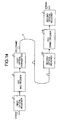
- Fig. 14 illustrates the overall structure of the optical transmission system according to the fourth embodiment of the present invention.
- This optical transmission system includes, instead of the second optical receiver 5 and the FEC demultiplexer 6 according to the third embodiment, a second optical receiver 115 and a FEC demultiplexer 116, respectively.
- the rest of the structure is identical to that of the third embodiment and identical parts in the two embodiments are assigned identical reference numerals.
- the second optical receiver 115 as well as converting optical signals received from an optical transmission channel 4 into electrical signals, carries out a soft decision process on the electrical signals, quantizes the binary data into j bits (where j is a positive integer of 2 or greater), and outputs a FEC frame as 3 parallel data stream of 13 Gbps to the FEC demultiplexer 116.
- the FEC demultiplexer 116 carries out a soft decision decoding based on the 3 parallel data stream.
- Fig. 15 is a block diagram of the FEC demultiplexer 116 shown in Fig. 14.
- the FEC demultiplexer 116 includes, instead of the third demultiplexer 81, the fourth demultiplexer 82, and the FEC frame bottom decoder 83 shown in Fig. 11, a third demultiplexer 121, a fourth demultiplexer 122, and a FEC frame bottom decoder 123, respectively.
- the rest of the structure is similar to the FEC demultiplexer shown in Fig. 11 and identical parts are assigned identical reference numerals.
- the third demultiplexer 121 demultiplexes j parallel data stream of 12 Gbps received from the second optical receiver 115 into (n ⁇ j) parallel data stream and outputs the (n ⁇ j) parallel data stream to the fourth demultiplexer 122.
- the fourth demultiplexer 122 demultiplexes the received (n ⁇ j) parallel data stream into (n ⁇ (m+i) ⁇ j) parallel data stream and outputs the (n ⁇ (m+i) ⁇ j) parallel data stream to the FEC frame bottom decoder 123.
- the FEC frame bottom decoder 123 carries out a soft decision decoding based on the received (n ⁇ (m+i) ⁇ j) parallel data stream and outputs a decoded (n ⁇ m) parallel data stream.
- the FEC demultiplexer 116 shown in Fig. 14 is explained next with reference to the detailed block diagram shown in Fig. 16.
- the FEC demultiplexer 116 includes, instead of the second 1 to 16 serial-parallel converter 101, the 1 to 9 serial-parallel converter 102 and the decoder 104 of the demultiplexer shown in Fig. 13, a (1 to 16) ⁇ 3 serial-parallel converter 131, a (1 to 9) ⁇ 3 serial-parallel converter 132, and a decoder 134, respectively.
- the rest of the structure is identical to the FEC demultiplexer shown in Fig. 3 and identical parts are assigned identical reference numerals.
- the (1 to 16) ⁇ 3 serial-parallel converter 131 multiplexes the received 3 data into a 48 (16 ⁇ 3) parallel data stream of 753 Mbps, splits this 48 parallel data stream into 3 streams, and outputs each of the 3 parallel data stream to a corresponding (1 to 9) ⁇ 3 serial-parallel converter 132 place next.
- Each (1 to 9) ⁇ 3 serial-parallel converter 132 demultiplexes the 27 ((9 ⁇ 3)) parallel data stream, collectively generates a 432 ((144x3)) of 84 Mbps, and outputs the 432 parallel data stream to a frame synchronization circuit 103.
- the frame synchronization circuit 103 checks the frame synchronization pattern from the overhead bit, detects the header position of the FEC frame, and outputs the frame-synchronized 432 parallel data stream to the decoder 134.
- the decoder 134 carries out the soft decision decoding of the 432 parallel data stream of 84 Mbps as 3 quantized 144 parallel data stream, and outputs, a decoded 128 parallel data stream to an overhead separating circuit 105.
- the subsequent steps are the same as those in the third embodiment.
- the decoder 134 comprises a first decoder 134a, which corresponds to the first decoder 104a, and a second decoder 134b, which corresponds to the second decoder 104b.
- the first decoder 134a decodes error-correcting code in the row direction and outputs, as a result, a 3 soft decision value.
- the second decoder 134b decodes the error-correcting code in the column direction and outputs, as a result, a3 soft decision value.
- the second decoder 134 then outputs, based on this soft decision value, the final decoding result.
- error correction capability improves remarkably with a soft decision decoding as compared to a hard decision decoding.
- a structure may be such that the frame synchronization circuit 103 may determine frame synchronization either by a 3 soft decision data or by a hard decision data.
- the third demultiplexer 121 the j parallel data stream, which is quantized into j bits by the soft decision process, into the (n ⁇ j) parallel data stream.
- the fourth demultiplexer 122 demultiplexes the (n ⁇ (m+i) ⁇ j) parallel data stream into the (n ⁇ m ⁇ j) parallel data stream and converts the j data quantized the soft decision process into a low rate (n ⁇ m) parallel data stream.
- the FEC frame bottom decoder 123 then carries out the error correction decoding. In this way, with a simple structure signals can be transmitted at a high rate. Further, the error correction capability of such a structure is considerably improved with enhanced transmission rate of a large amount of signals over long distances.
- BCH codes are used as error-correcting code in the row direction as well as the column direction.
- the error-correcting codes need not necessarily be only BCH codes.
- Other error-correcting codes such as Reed-Solomon codes or Reed-Muller codes may also be used.
- Convolution codes may also be used. However, it is preferable to use an error-correcting code in which the volume of redundant bits is fixed, such as in a block code, for maintaining transmission rate.
- error-correcting code in the row direction and the error-correcting code in the column direction may be of different types.
- the error-correcting codes in the two directions may be selected based on whether the criterion is maintenance of error correction capability or rate of transmission or simplicity of the structure.
- a sixth embodiment of the present invention is explained next.
- error correction encoding is carried out both in the row direction and the column direction. That is error correction encoding in the two directions that are mutually orthogonal.
- the row direction and the column directions are two different directions which are not mutually orthogonal and in which error-correcting codes are generated.
- Fig. 17 is a block diagram of a FEC multiplexer according to the sixth embodiment in an optical transmission system.
- Fig. 18 is a block diagram of a FEC demultiplexer according to the sixth embodiment.
- the overall structure of the optical transmission system is identical to the optical transmission system shown in Fig. 7.
- the structures of the FEC multiplexer 2 and the FEC demultiplexer 56 are different and are illustrated, respectively, in Fig. 17 and Fig. 18.
- the FEC multiplexer shown in Fig. 17 is identical to the FEC multiplexer shown in Fig. 2. However, the FEC multiplexer shown in Fig. 17 includes, instead of the second demultiplexer 12 and the FEC frame generating encoder 13 in Fig. 2, a second demultiplexer 142 and a FEC frame generating encoder 143, respectively, that are structurally different from their counterparts in Fig. 2.
- the second demultiplexer 142 demultiplexes n parallel data stream received from a first demultiplexer 11 into (n ⁇ m) parallel data stream and outputs the (n ⁇ m) parallel data stream to the FEC frame generating encoder 143.
- the FEC frame generating encoder 143 unlike the FEC frame generating encoder 13, carries out error correction encoding in a diagonal direction and not in the column direction. However, the FEC frame generating encoder 143 does carry out error correction encoding in the row direction. As a result, the direction in which error-correcting codes are generated are not orthogonal. However, as the directions are different, are treated as independent error-correcting codes during error correction decoding. Consequently, the bit errors are distributed between the error-correcting codes in the two directions. As a result, the error correction capability in this case is comparable to the error correction capability in the case in which code generation takes place in mutually orthogonal directions.
- the FEC frame generating encoder 143 Besides, as the FEC frame generating encoder 143 generates codes in the diagonal direction, there is no need to add an error-correcting code at the end (bottom) of the column direction. Therefore, an error-correcting code may be added only at the end of the row direction. As a result, the second demultiplexer 142 does not need to add an area corresponding to the redundant data area E5, making the structure simpler. In this case, the FEC frame generating encoder 143 carries out a rate change corresponding to the addition of error-correcting code in the diagonal direction.
- the FEC demultiplexer shown in Fig. 18 is identical to the FEC demultiplexer shown in Fig. 8. However, the FEC demultiplexer shown in Fig. 18 includes, instead of the FEC frame bottom decoder 53 and the third multiplexer 24 in Fig. 8, a FEC frame bottom decoder 153 and a third multiplexer 154, respectively, that are structurally different from their counterparts in Fig. 8.
- the FEC frame bottom decoder 153 carries out decoding based on the error-correcting code in the row direction that are added by the FEC frame generating encoder 143.
- the FEC frame bottom decoder 153 then carries out decoding based on the error-correcting code in the diagonal direction.
- the FEC frame bottom decoder 153 outputs to a third multiplexer 154 an (n ⁇ m) parallel data stream.
- the third multiplexer 154 like the second demultiplexer 142, has a simple structure since it does not need to remove an area corresponding to the redundant data area E5.
- Fig. 19 (a) and (b) are schematic diagrams that illustrate the error correction encoding process of the FEC frame generating encoder 143 shown in Fig. 17.
- Error correction encoding of the received (n ⁇ m) parallel data stream takes places first in the diagonal direction, as shown in Fig. 19 (b).
- the resulting error-correcting code is stored in a redundant data area E15 which is located at the end of the row direction.
- error correction encoding in the row direction including the redundant data area E15, is carried out.
- the resulting error-correcting code is stored in a redundant data area E14 which is located after the redundant data area E15. Consequently, the error-correcting code generated in the row direction, which is at 45° with respect to the diagonal direction, and is independent of the error-correcting code generated in the diagonal direction.
- error correction encoding is shown to be carried out in a single frame.
- multi-frame error correction encoding may also be carried out and an error correction encoding for this error correction encoding may also be carried out.
- Fig. 20 illustrates an example of the error correction encoding process in a multi-frame setup.
- Frames F1 and F2 are considered as a single frame and error correction encoding is carried out for them in the diagonal direction.
- the resulting error-correcting code is split and stored in a redundant data area E25 for the frame F1 and a redundant data area E35 for the frame F2.
- error correction encoding is carried out in the row direction of the frames F1 and F2, which now include the redundant data areas E25 and E35.
- the resulting error-correcting codes are stored in a redundant data area E24 for the frame F1 and a redundant data area E34 for the frame F2.
- an error correction decoding is carried out based on the error-correcting codes in the row direction stored in the redundant data areas E24 and E34 of the frames F1 and F2, respectively, which also includes redundant data areas E25 and E35.
- an error correction decoding is carried out, considering the frames F1 and F2 as a single frame, based on the error-correcting code in the diagonal direction that is split and stored in the redundant data areas E25 and E35 of the frames F1 and F2, respectively.
- error-correcting code is generated in the diagonal direction as well as the row direction.
- the structures of the second demultipelxer 142 and the third multiplexer 154 are simplified as a combined error correction encoding is carried out. As a result, high rate transmission with high error correction capability can be achieved with a simple structure.
- the FEC frame bottom decoder in the first stage carries out error correction decoding using the error-correcting code in the row direction and then in the second stage carries out error correction decoding using the error-correcting code in the column direction or the diagonal direction, as the case may be.
- error correction decoding is carried out by repeating plural first and second stages in a continuous manner.
- the FEC frame bottom decoder carries out decoding of the turbo codes, enhancing the error correction capability.
- Using a soft decision process can particularly result in a superior error correction capability.
- Fig. 21 is a block diagram of a decoder according to the seventh embodiment of the present invention employed in an optical transmission system.
- a first decoder 161 outputs to an interleaver 162 a soft decision value obtained by decoding error-correcting code in the row direction.
- a second decoder 163 outputs to a deinterleaver 164 a soft decision value obtained by decoding error-correcting code in the column or diagonal direction for the data interleaved by the interleaver 162.
- the deinterleaver 164 outputs the soft decision value to the first decoder 161. In this way, the decoding by the first decoder 161 and the second decoder 163 is repeated a specified number of times.
- the final decoding result is output from the second decoder. Since the same first decoder 161, interleaver 162, second decoder 163, and deinterleaver 164 carry out the cycles repeatedly, the structure remains simple.
- the fixed stuff area E3 is used as an overhead data area E2.
- the amount of data required for maintenance and operation of an optical transmission system can be further increased.
- a demultiplexer receives and demultiplexes a serial data stream into plural bit parallel data stream.
- a first encoder carries out error correction encoding in a first direction of a matrix constituted by the parallel data stream and adds a first error-correcting code to the parallel data stream.
- a second encoder carries out error correction encoding in a second direction of the matrix constituted by the parallel data stream and adds a second error-correcting code to the parallel data stream.
- a multiplexer multiplexes the parallel data stream encoded by the first encoder and the second encoder and outputs a serial data stream.
- the error-correcting codes in the two directions are independent of each other because of the serial data stream, and the bit errors are distributed. Consequently, the transmission rate of the transmission data itself is enhanced and besides the increase in the transmission rate due to the redundant bit. Even if there is deterioration in the transmission characteristics, error correction capability can be enhanced.
- the demultiplexer demultiplexes the received serial data stream into n parallel data stream (where n is a positive integer) and demultiplexes the n parallel data stream further into (n ⁇ (m-i)) parallel data stream (where m and i are positive integers and m is greater than i).
- the first encoder and the second encoder output the (n ⁇ (m-i)) parallel data stream as (n ⁇ m) parallel data stream to the multiplexer.
- the multiplexer multiplexes the received (n ⁇ m) parallel data stream into n parallel data stream and outputs the n parallel data stream as a serial data stream. Consequently, an encoding that is consistent with the error correction encoding is reliably carried out.
- the demultiplexer demultiplexes the received serial data stream into n parallel data stream (where n is a positive integer) and demultiplexes the n parallel data stream further into (n ⁇ m) parallel data stream (where m is a positive integer).
- the first encoder and the second encoder outputs the received (n ⁇ m) parallel data stream as (n ⁇ (m+i)) parallel data stream (where m and i are positive integers and m is greater than i) to the multiplexer.
- the multiplexer multiplexes the received (n ⁇ (m+i)) parallel data stream into n parallel data stream and outputs the n parallel data stream as a serial data stream. Consequently, an encoding that is consistent with the error correction encoding is reliably carried out.
- the first encoder carries out an error correction encoding in the column direction of the matrix constituted by the parallel data stream and adds the resulting first error-correcting code to the parallel data stream.
- the second encoder carries out error correction encoding and adds the resulting second error-correcting code to the parallel data stream.
- the error correction encoding by the first encoder is independent of the error correction encoding by the second encoder. Consequently, an enhanced error correction capability is achieved.
- the first encoder adds the first error correcting code to a specific row at the end of columns of the parallel data stream and the second encoder adds the second error correcting code to a specific column at the end of the rows of the parallel data stream. Consequently, a soft process can be carried out corresponding to the matrix form of the parallel data stream.
- the demultiplexer adds to the parallel data stream an area in which the first error-correcting code generated by the first encoder is stored.
- the load on the first encoder and the second encoder is reduced as the areas for storing the error correcting codes are created when there is flexibility during low rate.
- areas for error-correcting codes are formed using a simple structure.
- the first encoder carries out error correction encoding in a diagonal direction of the matrix constituted by the parallel data stream and adds the resulting error-correcting code to the parallel data stream.
- the second encoder carries out error correction encoding in the row direction of the matrix constituted by the parallel data stream and adds the resulting error-correcting code to the parallel data stream.
- the directions of the error correction encoding by the first encoder and the second encoder are therefore not orthogonal. Consequently, even if the two error-correcting codes are of the same type, independent error-correcting codes that are soft and multiplexed can be realized.
- the first encoder adds the first error-correcting code to a specific row at the end of the columns of the parallel data stream.
- the second encoder adds the second error-correcting code adjacent to error-correcting code added by the first encoder. Consequently, soft processing corresponding to the matrix form of the parallel data stream can be carried out.
- the second encoder carries out error correction encoding for the parallel data stream which includes the first error-correcting code added by the first encoder and adds the resulting second error-correcting code to the parallel data stream.
- the second encoder also corrects the errors in the error-correcting code generated by the first encoder. As a result, an enhanced error correction capability is achieved.
- the first error-correcting code added by the first encoder and the second error-correcting code added by the second encoder differ in their coding systems. Consequently, a soft error correction multiplexer, suited to the system in which the error correction multiplexer is implemented, can be realized.
- the first error-correcting code added by the first encoder and the second error-correcting code added by the second encoder are block codes. Consequently, the capacity of the error-correcting codes can be fixed. As a result, the structure of the encoders can be kept simple and a stable operation of the encoders is achieved.
- the first error-correcting code added by the first encoder and the second error-correcting code added by the second encoder are calculated in the same block coding system, and differ in the coding conditions. As a result, enhanced softness is maintained and the encoding process is carried out with effectiveness.
- the parallel data stream includes a data area, an overhead data area in the column direction that is added to the beginning of the row direction of the data area, and a fixed stuff area, which absorbs the difference arising from the parallel data stream matrix. Consequently, demultiplexing and multiplexing are easily carried out.
- the quantity of the overhead bits is increased by storing the overhead bits in the fixed stuff area. Consequently, the maintenance and operation of the system in which the error correction multiplexer is implemented can be carried out more reliably without having to increase the transmission capacity.
- a demultiplexer demultiplexes into parallel data stream a multiplexed serial data stream of plural error-correcting codes generated by error correction encoding in two different directions of a parallel data stream.
- a decoder gradually decodes the parallel data stream by the plural error-correcting codes and outputs a decoded parallel data stream.
- a multiplexer multiplexes the parallel data stream decoded by the decoder and outputs a serial data stream.
- the decoding is carried out by the decoder using the independent error-correcting codes. Consequently, the transmission rate of the transmission data itself can be enhanced. Further, transmission rate can be enhanced by addition of the redundant bits. Besides, even if the transmission characteristic deteriorates, an enhanced error correction capability can be achieved.
- the demultiplexer demultiplexes a received serial data stream into n parallel data stream (where n is a positive integer), and further into (n ⁇ m) parallel data stream (where m is a positive integer).
- the decoder converts the received (n ⁇ m) parallel data stream into (n ⁇ (m-i)) parallel data stream (where i is a positive integer, and m is greater than i), and outputs the (n ⁇ (m-i)) parallel data stream to the multiplexer.
- the multiplexer multiplexes the (n ⁇ (m-i)) parallel data stream into n parallel data stream and converts and outputs the n parallel data stream as a serial data stream. Consequently, a decoding that is consistent with the error correction encoding is reliably carried out.
- the demultiplexer demultiplexes the received serial data stream into n parallel data stream (where n is a positive integer) and further into (n ⁇ (m+i)) parallel data stream (where m and i are positive integer, and m is greater than i).
- the decoder converts the received (n ⁇ (m+i)) parallel data stream into (n ⁇ m) parallel data stream and outputs the (n ⁇ m) parallel data stream to the multiplexer.
- the multiplexer multiplexes the received (n ⁇ m) parallel data stream into n parallel data stream and converts and outputs the n parallel data stream as a serial data stream. Consequently, a decoding that is consistent with the error correction encoding is reliably carried out.
- a first decoder extracts a first error-correcting code from the parallel data stream received from the demultiplexer, carries out error correction decoding, based on the extracted error-correcting code, in a first direction of the matrix constituted by the parallel data stream, and outputs the result of the decoding.
- a second decoder extracts a second error-correcting code from the parallel data stream received from the demultiplexer, carries out error correction decoding, based on the extracted error-correcting code, in a second direction of the matrix constituted by the parallel data stream, and outputs the decoding result.
- the second decoder carries out error correction decoding using the decoding result of the first decoder. In this way, the remaining bit errors are reliably corrected. Consequently, an enhanced error correction capacity is achieved.
- the demultiplexer demultiplexes a parallel bit stream that is quantized into plural bits by a soft decision process.
- the first decoder and the second decoder carry out soft decision decoding, wherein the second decoder uses the decoding result of the first decoder. Consequently, an enhanced error correction capability due to soft decision decoding is achieved.
- the demultiplexer demultiplexes a parallel bit stream that is quantized into plural bits by a soft decision process.
- the first decoder and the second decoder which are connected in series in multiple stages, carry out an iterative soft decision process. Consequently, an enhanced error correction capability is achieved.
- the second decoder carries out an iterative soft decision decoding in which the decoding result is repeatedly input into the first decoder a predetermined number of times. Consequently, an enhanced error correction capability is achieved.
- a first optical receiver converts received an optical signal into an electrical signals. Any one of the error correction multiplexers according to the present invention processes the serial data stream output from the first optical receiver.
- a first optical transmitter converts into an optical signal the electrical signal output from the error correction multiplexer and transmits the optical signal to the optical transmission channel.
- a second optical receiver converts the optical signal received from the optical transmission channel into an electrical signal. Any one of the error correction demultiplexers according to the present invention processes the electrical signals output from the second optical receiver.
- a second optical transmitter converts the electrical signal output from the error correction demultiplexer into an optical signal. Consequently, the transmission rate of the transmission data itself can be enhanced. Further, transmission rate can be enhanced by addition of the redundant bits. Besides, even if the transmission characteristic deteriorates, an enhanced error correction capability can be achieved. As a result, an optical transmission system that can transmit a large amount of signals over long distance can be realized.
- the second optical receiver carries out a soft decision process and carries out a soft decision decoding based on the result of the soft decision process. Consequently, an optical transmission system with an enhanced error correction capability is achieved.
- a demultiplexing step received serial data stream is demultiplexed into parallel data stream.
- error correction encoding is carried out in a first direction of the matrix constituted by the parallel data stream.
- error correction encoding is carried out in a second direction of the matrix constituted by the parallel data stream.
- the resulting first and second error-correcting codes are added to the parallel data stream.
- the parallel data stream, to which the plural error-correcting codes are added in the first and second encoding steps is multiplexed and output as a serial data stream. Consequently, the transmission rate of the transmission data itself can be enhanced. Further, transmission rate can be enhanced by addition of the redundant bits. Besides, even if the transmission characteristic deteriorates, an enhanced error correction capability can be achieved.
- the received serial data stream is demultiplexed into n parallel data stream (where n is a positive integer) and further into (n ⁇ (m-i)) parallel data stream (where m and i are positive integers, and m is greater than i).
- the received (n ⁇ (m-i)) parallel data stream is converted and output as (n ⁇ m) parallel data stream.
- the (n ⁇ m) parallel data stream is multiplexed into n parallel data stream and output as a serial data stream. Consequently, an encoding that is consistent with the error correction encoding is achieved.
- the received serial data stream is demultiplexed into n parallel data stream (where n is a positive integer) and further into (n ⁇ m) parallel data stream (where m is a positive integer).
- the received (n ⁇ m) parallel data stream is converted and output as (n ⁇ (m+1)) parallel data stream (where i is a positive integer, and m is greater than i).
- the (n ⁇ (m+i)) parallel data stream is multiplexed into n parallel data stream and output as a serial data stream. Consequently, an encoding that is consistent with the error correction encoding is achieved.
- an error correction encoding is carried out in the column direction of the matrix formed by the parallel data stream and the resulting error-correcting code is added to the parallel data stream.
- an error correction encoding is carried out in the row direction of the matrix formed by the parallel data stream, and the resulting error-correcting code is added to the parallel data stream.
- a first error-correcting code is added to a specific row at the end of the columns of the parallel data stream.
- a second error-correcting code is added to a specific column at the end of the rows of the parallel data stream. Consequently, a soft decision process can be carried out corresponding to the matrix form of the parallel data stream.
- the first encoding step error correction encoding is carried out a diagonal direction of the matrix constituted by the parallel data stream and the resulting error-correcting code is added to the parallel data stream.
- error correction encoding is carried out in the row direction of the matrix constituted by the parallel data stream and the resulting error-correcting code is added to the parallel data stream.
- the directions of the error correction encoding by the first encoder and the second encoder are therefore not orthogonal. Consequently, even of the two error-correcting codes are of the same type, independent error-correcting codes that are soft and multiplexed can be realized.
- the first error-correcting code is added to a specific row at the end of the columns of the parallel data stream.
- the second error-correcting code is added adjacent to the error-correcting code added by the first encoder. Consequently, a soft processing corresponding to the matrix form of the parallel data stream can be carried out.
- the second encoding step error correction encoding is carried out for the parallel data stream which includes the first error-correcting code added by the first encoder and the resulting second error-correcting code to is added to the parallel data stream.
- any errors in the error-correcting codes that are generated in the first encoding step are also corrected in the second encoding step.
- an enhanced error correction capability is achieved.
- the first error-correcting code added in the first encoding step and the second error-correcting code added in the second encoding step differ in their coding systems. Consequently, a soft error correction multiplexer, suited to the system in which the error correction multiplexer is implemented, can be realized.
- the first error-correcting coded added in the first encoding step and the second error-correcting code added in the second encoding step are block codes. Consequently, the capacity of the error-correcting codes can be fixed. As a result, the structure of the encoders can be kept simple and a stable operation of the encoders is achieved.
- the first error-correcting code added in the first encoding step and the second error-correcting code added in the second encoding step are calculated in the same block coding system, and differ in the coding conditions. As a result, enhanced softness is maintained and the encoding process is carried out with effectiveness.
- the quantity of the overhead bits is increased by storing the overhead bits in the fixed stuff area. Consequently, the maintenance and operation of the system in which the error correction multiplexer is implemented can be carried out more reliably without having to increase the transmission capacity.
- the serial data stream created in the multiplexing step is demultiplexed into parallel data stream.
- a first error-corrected code is extracted from the parallel data stream created in the demultiplexing step at the receiving end and, based on the extracted error-correcting code, error correction decoding is carried out in a first direction of the matrix formed by the parallel data stream, and the decoding result is output.
- a second error-correcting code is extracted from the parallel data stream created in the demultiplexing step at the receiving end and, based on the extracted error-correcting code, error correction decoding is carried out in a second direction of the matrix formed by the parallel data stream, and the decoding result is output.
- the parallel data stream is multiplexed and output as a serial data stream. Consequently, the transmission rate of the transmission data itself is enhanced besides the increase in the transmission rate due to the redundant bit. Even if there is deterioration in the transmission characteristics, error correction capability can be enhanced.
- a parallel bit stream is quantized into plural bits by a soft decision process.
- soft decision decoding wherein the decoding result of the first decoding step is used in the second decoding step, is carried out. Consequently, an enhanced error correction capability due to soft decision decoding is achieved.
- a parallel bit stream is quantized into plural bits by a soft decision process.
- iterative soft decision process is carried out, using the decoding result of the first decoder, for a predetermined number of times. Consequently, an enhanced error correction capability is achieved.
- An error correction multiplexer, an error correction demultiplexer, an optical transmission system employing the error correction multiplexer and the error correction demultiplexer, and an error correction multiplexed transmission method according to the present invention is suitable for correction of bit errors caused by deterioration of signal-to-noise ratio, based on forward error correction, and implementing long-haul, high-capacity transmission.
Landscapes
- Engineering & Computer Science (AREA)
- Computer Networks & Wireless Communication (AREA)
- Signal Processing (AREA)
- Physics & Mathematics (AREA)
- Probability & Statistics with Applications (AREA)
- Theoretical Computer Science (AREA)
- Mathematical Physics (AREA)
- Detection And Prevention Of Errors In Transmission (AREA)
- Optical Communication System (AREA)
- Error Detection And Correction (AREA)
- Detection And Correction Of Errors (AREA)
- Time-Division Multiplex Systems (AREA)
Abstract
A first demultiplexer (11) and a second demultiplexer (12)
receive and demultiplex STM-64 data to generate parallel data. A FEC
frame generating encoder (13) carries out error correction encoding
operation in a column direction of the parallel data that constitutes a
matrix, adds a resulting error correcting code to the parallel data,
carries out error correction encoding operation in a row direction of the
parallel data, and further adds a resulting error-correcting code to the
parallel data. A first multiplexer (14) and a second multiplexer (15)
multiplex the error-correction-encoded parallel data, and output the
data as a FEC frame.
Description
Error correction multiplexer, error correction demultiplexer,
optical transmission system employing the error correction multiplexer
and the error correction demultiplexer, and method of error correction
multiplexing transmission
The present invention relates to an error correction multiplexer,
an error correction demultiplexer, an optical transmission system
employing the error correction multiplexer and the error correction
demultiplexer, and a method of error correction multiplexing
transmission that corrects bit errors caused by deterioration of
signal-to-noise ratio, based on forward error correction (FEC), and to
implement long-haul, high-capacity transmission.
One of the popular optical transmission systems that
compensates for deterioration of the optical signal-to-noise ratio based
on forward error correction (FEC) is the one recommended by ITU-T
G.975. Fig. 22 is a block diagram of an FEC multiplexer at a
transmitting end that employs the FEC method recommended by ITU-T
G.975. Fig. 23 is a block diagram of an FEC demultiplexer at a
receiving end that employs the FEC method.
As shown in Fig. 22, a first demultiplexer 211 receives and
demultiplexes an STM-16 data of 2.5 Gbps into 16 parallel data stream
of 156 Mbps and outputs the 16 parallel data stream to a second
demultiplexer 212. The second demultiplexer 212 receives and further
demultiplexes the 16 parallel data stream into 128 parallel data stream
of 19 Mbps, and outputs the 128 parallel data stream to a first rate
converter 213.
The first rate converter 213 receives the 128 parallel data
stream of 19 Mbps and adds a redundant data area to the data stream.
The first rate converter 213 then rate-converts the 128 parallel data
stream of 19 Mbps into 128 parallel data stream of 21 Mbps and outputs
it to an overhead inserting circuit 214. The overhead inserting circuit
214 inserts an overhead (OH) bit such as a frame synchronization data
that is necessary for the maintenance and the operation of the optical
system, and outputs the overhead (OH) data to an encoder 215.
The encoder 215 carries out error correction encoding by means
of Reed Solomon (255,239) codes and outputs the encoded data to a
first multiplexer 216. The first multiplexer 216 multiplexes the 128
parallel data stream into 16 parallel data stream of 167 Mbps and
outputs the 16 parallel data stream to a second multiplexer 217. The
second multiplexer 217 receives the 16 parallel data stream and further
multiplexes it to a FEC frame of 2.66 Gbps. The second multiplexer
217 then converts the FEC frame of 2.66 Gbps into an optical signal via
an optical transmitter and outputs the optical signal to an optical
transmission channel.
The optical signal from the optical transmission channel is
converted into an electrical signal by an optical receiver and output the
electrical signal to a third demultiplexer 221. The third demultiplexer
221 receives and demultiplexes the FEC frame of 2.66 Gbps into 16
parallel data stream of 167 Mbps, and outputs the 16 parallel data
stream of 167 Mbps to a fourth demultiplexer 222. The fourth
demultiplexing 222 receives the 16 parallel data stream, further
demultiplexes it into the 128 parallel data stream of 21 Mbps, and
outputs the 128 parallel data stream of 21 Mbps to a frame
synchronization circuit 223.
The frame synchronization circuit 223 detects the header
position of the FEC frame based on the frame synchronization data
included in an overhead data area and outputs frame-synchronized data
to a decoder 224. The decoder 224 detects and corrects bit errors by
means of the Reed Solomon (255,239) codes and outputs the corrected
data to an overhead separating circuit 225.
The overhead separating circuit 225 separates the overhead
data area. A second rate converter 226 removes the redundant data
area in which the error correction codes are stored, converts the
remaining data into the 128 parallel data stream of 19 Mbps, and
outputs it to a third multiplexer 227. The third multiplexer 227 receives
and multiplexes the 128 parallel data stream of 19 Mbps to the 16
parallel data stream of 156 Mbps, and outputs the 16 parallel data
stream of 156 Mbps to a fourth multiplexer 228. The fourth multiplexer
228 receives and multiplexes the 16 parallel data stream of 156 Mbps
and outputs it as the STM-16 data stream of 2.5 Gbps.
The FEC frame is composed of subframes 1 through 128 that
include one column of the overhead bit, 238 columns of the STM-16
data, and 16 columns of a Reed Solomon (255,239) redundant data.
The error correction encoding is carried out after every eighth
subframe.
For instance, in the subframes 1 through 8, the error correction
encoding is carried out for the overhead bit and the STM-16 data, and
the Reed Solomon (255,239) redundant data is stored in columns R0-0
through R0-15. As shown in Fig. 24B, the FEC frame is generated
sequentially multiplexing the subframes 1 through 128. If we assume
that the Reed Solomon (255,239) codes 0 through 15 are multiplexed
for 'f' number of times, then Fig. 24 shows an example when f = 16.
The transmission rate in the FEC frame increases 15/14 times
with respect to the original rate of the STM-16. Hence, the
transmission rate of the FEC frame becomes 2.66 Gbps. In this way,
the bit errors can be corrected by adding the FEC frame and a high
quality service can be offered in an optical transmission system.
Hence, an optical transmission system that facilitates transmission of
high capacity of signals over long distances can be built.
When a Reed Solomon (127,111) encoding that has reduced
error correction codes is carried out on the Reed Solomon (255,239)
codes by, for instance, reducing the STM-16 data of the subframes from
238 columns to 110 columns, the percentage of the redundant data
corresponding to the data increases and the error correction capability
can be improved.
However, in the optical transmission system described above,
when the transmission distance is increased or the number of
wavelengths is increased using a wavelength multiplexing system,
deterioration of the signal-to noise ratio is considerable. A
conventional way to prevent the deterioration of the signal-to noise ratio
is to reduce the error correction codes to improve the constant error
correction capability. However, when the error correction codes are
reduced, the percentage of the redundant data with respect to the data
that is supposed to be transmitted increases, resulting in an increase in
the transmission rate. Thus, an optical transmission system that
maintains a certain quality and facilitates transmission of high capacity
of signals over a long distance cannot be built.
For instance, in the Reed Solomon (127,111) encoding, the
transmission rate of the FEC frame becomes 127/111 times to 2.89
Gbps with respect to the rate of 2.5 Gbps of the STM-16 data, resulting
in more deterioration of the optical transmission characteristics. As a
result, even if the code length is reduced, an optical transmission
system that maintains a certain quality and facilitates transmission of
high capacity of signals over a long distance cannot be built.
It is an object of the present invention to provide an optical
transmission system and a method of error correction multiplexing
transmission that employs an error correction multiplexer and an error
correction demultiplexer, which enables to considerably improve the
error correction capability even if the data rate increases, the
transmission rate increases according to. the increase in the percentage
of redundant data with respect to the data, and the optical characteristic
deteriorates.
According to the present invention, a demultiplexer receives and
demultiplexes a serial data stream into a parallel data stream. A first
encoder carries out error correction encoding in a first direction of a
matrix constituted by the parallel data stream and adds a first
error-correcting code to the parallel data stream. A second encoder
carries out error correction encoding in a second direction of the matrix
constituted by the parallel data stream and adds a second
error-correcting code to the parallel data stream. A multiplexer
multiplexes the parallel data stream encoded by the first encoder and
the second encoder and outputs a serial data stream. The
error-correcting codes in the two directions are independent of each
other because of the serial data stream, and the bit errors are
distributed.
According to the present invention, the demultiplexer
demultiplexes the received serial data stream into n parallel data
stream (where n is a positive integer) and demultiplexes the n parallel
data stream further into (n×(m-i)) parallel data stream (where m and i
are positive integers and m is greater than i). The first encoder and
the second encoder output the (n×(m-i)) parallel data stream as (n×m)
parallel data stream to the multiplexer. The multiplexer multiplexes the
received (nxm) parallel data stream into n parallel data stream and
outputs the n parallel data stream as a serial data stream.
An error correction multiplexer according to the next invention,
the demultiplexer demultiplexes the received serial data stream into n
parallel data stream (where n is a positive integer) and demultiplexes
the n parallel data stream further into (n×m) parallel data stream (where
m is a positive integer). The first encoder and the second encoder
outputs the received (n×m) parallel data stream as (n×(m+i)) parallel
data stream (where m and i are positive integers and m is greater than
i) to the multiplexer. The multiplexer multiplexes the received
(n×(m+i)) parallel data stream into n parallel data stream and outputs
the n parallel data stream as a serial data stream.
According to the present invention, the demultiplexer
demultiplexes the received serial data stream into n parallel data
stream (where n is a positive integer) and demultiplexes the n parallel
data stream further into (n×m) parallel data stream (where m is a
positive integer). The first encoder and the second encoder outputs
the received (n×m) parallel data stream as (n×(m+i)) parallel data
stream (where m and i are positive integers and m is greater than i) to
the multiplexer. The multiplexer multiplexes the received (n×(m+i))
parallel data stream into n parallel data stream and outputs the n
parallel data stream as a serial data stream.
According to the present invention, the first encoder carries out
en error correction encoding in the column direction of the matrix
constituted by the parallel data stream and adds the resulting first
error-correcting code to the parallel data stream. The second encoder
carries out error correction encoding and adds the resulting second
error-correcting code to the parallel data stream. The error correction
encoding by the first encoder is independent of the error correction
encoding by the second encoder.
According to the present invention, the first encoder adds the
first error correcting code to a specific row at the end of columns of the
parallel data stream and the second encoder adds the second error
correcting code to a specific column at the end of the rows of the
parallel data stream.
According to the present invention, the demultiplexer adds to the
parallel data stream an area in which the first error-correcting code
generated by the first encoder is stored. The areas for storing the
error correcting codes are created when there is flexibility during low
rate.
According to the present invention, the first encoder carries out
error correction encoding in a diagonal direction of the matrix
constituted by the parallel data stream and adds the resulting
error-correcting code to the parallel data stream. The second encoder
carries out error correction encoding in the row direction of the matrix
constituted by the parallel data stream and adds the resulting
error-correcting code to the parallel data stream. The directions of the
error correction encoding by the first encoder and the second encoder
are therefore not orthogonal.
According to the present invention, the first encoder adds the
first error-correcting code to a specific row at the end of the columns of
the parallel data stream. The second encoder adds the second
error-correcting code adjacent to error-correcting code added by the
first encoder.
According to the present invention, the second encoder carries
out error correction encoding for the parallel data stream which includes
the first error-correcting code added by the first encoder and adds the
resulting second error-correcting code to the parallel data stream. In
this way, the second encoder also corrects the errors in the
error-correcting code generated by the first encoder.
According to the present invention, the first error-correcting
code added by the first encoder and the second error-correcting code
added by the second encoder differ in their coding systems.
According to the present invention, the first error-correcting
code added by the first encoder and the second error-correcting code
added by the second encoder are block codes. Consequently, the
capacity of the error-correcting codes can be fixed.
According to the present invention, the first error-correcting
code added by the first encoder and the second error-correcting code
added by the second encoder are calculated in the same block coding
system, and differ in the coding conditions.
According to the present invention, the parallel data stream
includes a data area, an overhead data area in the column direction
that is added to the beginning of the row direction of the data area, and
a fixed stuff area, which absorbs the difference arising from the parallel
data stream matrix.
According to the present invention, the quantity of the overhead
bits is increased by storing the overhead bits in the fixed stuff area.
According to the present invention, a demultiplexer
demultiplexes into parallel data stream a multiplexed serial data stream
of plural error-correcting codes generated by error correction encoding
in two different directions of a parallel data stream. A decoder
gradually decodes the parallel data stream by the plural error-correcting
codes and outputs a decoded parallel data stream. A multiplexer
multiplexes the parallel data stream decoded by the decoder and
outputs a serial data stream. The decoding is carried out by the
decoder using the independent error-correcting codes.
According to the present invention, the demultiplexer
demultiplexes a received serial data stream into n parallel data stream
(where n is a positive integer), and further into (n×m) parallel data
stream (where m is a positive integer). The decoder converts the
received (n×m) parallel data stream into (n×(m-i)) parallel data stream
(where i is a positive integer, and m is greater than i), and outputs the
(n×(m-i)) parallel data stream to the multiplexer. The multiplexer
multiplexes the (n×(m-i)) parallel data stream into n parallel data stream
and converts and outputs the n parallel data stream as a serial data
stream.
According to the present invention, the demultiplexer
demultiplexes the received serial data stream into n parallel data
stream (where n is a positive integer) and further into (n×(m+i)) parallel
data stream (where m and i are positive integer, and m is greater than i).
The decoder converts the received (n×(m+i)) parallel data stream into
(nℓm) parallel data stream and outputs the (n×m) parallel data stream
to the multiplexer. The multiplexer multiplexes the received (n×m)
parallel data stream into n parallel data stream and converts and
outputs the n parallel data stream as a serial data stream.
According to the present invention, a first decoder extracts a
first error-correcting code from the parallel data stream received from
the demultiplexer, carries out error correction decoding, based on the
extracted error-correcting code, in a first direction of the matrix
constituted by the parallel data stream, and outputs the result of the
decoding. A second decoder extracts a second error-correcting code
from the parallel data stream received from the demultiplexer, carries
out error correction decoding, based on the extracted error-correcting
code, in a second direction of the matrix constituted by the parallel data
stream, and outputs the decoding result. As a result, the bit errors are
distributed and decoded reliably.
According to the present invention, the second decoder carries
out error correction decoding using the decoding result of the first
decoder. In this way, the remaining bit errors are reliably corrected.
According to the present invention, the demultiplexer
demultiplexes a parallel bit stream that is quantized into plural bits by a
soft decision process. The first decoder and the second decoder carry
out soft decision decoding, wherein the second decoder uses the
decoding result of the first decoder.
According to the present invention, the demultiplexer
demultiplexes the parallel data stream that is quantized into plural bits
by a soft decision process. The first decoder and the second decoder,
which are connected in series in multiple stages, carry out an iterative
soft decision decoding.
According to the present invention the second decoder decodes
data by iterative soft decision decoding in which the result is repeatedly
input into the first decoder a predetermined number of times.
An optical transmission system according to the next invention
comprises a first optical receiver that receives and converts an optical
signal to an electrical signal, an error correction multiplexer according
to any one of the inventions described above that multiplexes a serial
data stream output from the first optical receiver, a first optical
transmitter that converts the electrical signal output from the error
correction multiplexer to the optical signal and transmits the optical
signal to an optical transmission channel, a second optical receiver that
converts the optical signal output from the optical transmission channel
into an electrical signal, an error correction demultiplexer according to
any one of the inventions described above that demultiplexes a parallel
data stream output from the second optical receiver, and a second
optical transmitter that converts the electrical signal output from the
error correction demultiplexer into an optical signal.
According to the present invention, a first optical receiver
converts received an optical signal into an electrical signals. Any one
of the error correction multiplexers according to the present invention
processes the serial data stream output from the first optical receiver.
A first optical transmitter converts into an optical signal the electrical
signal output from the error correction multiplexer and transmits the
optical signal to the optical transmission channel. A second optical
receiver converts the optical signal received from the optical
transmission channel into an electrical signal. Any one of the error
correction demultiplexers according to the present invention processes
the electrical signals output from the second optical receiver. A
second optical transmitter converts the electrical signal output from the
error correction demultiplexer into an optical signal.
According to the present invention, the second optical receiver
carries out a soft decision process and carries out a soft decision
decoding based on the soft decision process.
According to the present invention, in a demultiplexing step,
received serial data stream is demultiplexed into parallel data stream.
In a first encoding step, error correction encoding is carried out in a first
direction of the matrix constituted by the parallel data stream. In a
second encoding step, error correction encoding is carried out in a
second direction of the matrix constituted by the parallel data stream.
The resulting first and second error-correcting codes are added to the
parallel data stream. In a multiplexing step, the encoded parallel data
stream, to which the plural error-correcting codes are added in the first
and second encoding steps, is multiplexed and output as a serial data
stream.
According to the present invention, in the demultiplexing step,
the received serial data stream is demultiplexed into n parallel data
stream (where n is a positive integer) and further into (n×(m-i)) parallel
data stream (where m and i are positive integers, and m is greater than
i). In the first encoding step and the second encoding step, the
received (n×(m-i)) parallel data stream is converted and output as
(n×m) parallel data stream. In the multiplexing step, the (n×m) parallel
data stream is multiplexed into n parallel data stream and output as a
serial data stream.
According to the present invention, in the demultiplexing step,
the received serial data stream is demultiplexed into n parallel data
stream (where n is a positive integer) and further into (n×m) parallel
data stream (where m is a positive integer). In the first encoding step
and the second encoding step, the received (n×m) parallel data stream
is converted and output as (n×(m+1)) parallel data stream (where i is a
positive integer, and m is greater than i). In the multiplexing step, the
(n×(m+i)) parallel data stream is multiplexed into n parallel data stream
and output as a serial data stream.
According to the present invention, in the first encoding step, an
error correction encoding is carried out in the column direction of the
matrix formed by the parallel data stream and the resulting
error-correcting code is added to the parallel data stream. In the
second encoding step, an error correction encoding is carried out in the
row direction of the matrix formed by the parallel data stream, and the
resulting error-correcting code is added to the parallel data stream.
The error-correcting code generated in the first encoding step is
independent of the error-correcting code generated in the second
encoding step.
According to the present invention, in the first encoding step, a
first error-correcting code is added to a specific row at the end of the
columns of the parallel data stream. In the second encoding step, a
second error-correcting code is added to a specific column at the end of
the rows of the parallel data stream.
According to the present invention, in the first encoding step,
error correction encoding is carried out a diagonal direction of the
matrix constituted by the parallel data stream and the resulting
error-correcting code is added to the parallel data stream. In the
second encoding step, error correction encoding is carried out in the
row direction of the matrix constituted by the parallel data stream and
the resulting error-correcting code is added to the parallel data stream.
The directions of the error correction encoding by the first encoder and
the second encoder are therefore not orthogonal.
According to the present invention, in the first encoding step, the
first error-correcting code is added to a specific row at the end of the
columns of the parallel data stream. In the second encoding step, the
second error-correcting code is added adjacent to the error-correcting
code added by the first encoder.
According to the present invention, in the second encoding step,
error correction encoding is carried out for the parallel data stream
which includes the first error-correcting code added by the first encoder
and the resulting second error-correcting code to is added to the
parallel data stream. In this way, any errors in the error-correcting
codes that are generated in the first encoding step are also corrected in
the second encoding step.
According to the present invention, the first error-correcting
code added in the first encoding step and the second error-correcting
code added in the second encoding step differ in their coding systems.
According to the present invention, the first error-correcting
coded added in the first encoding step and the second error-correcting
code added in the second encoding step are block codes.
Consequently, the capacity of the error-correcting codes can be fixed.
Consequently, the capacity of the error-correcting codes can be fixed.
According to the present invention, the first error-correcting
code added in the first encoding step and the second error-correcting
code added in the second encoding step are calculated in the same
block coding system, and differ in the coding conditions.
According to the present invention, the quantity of the overhead
bits is increased by storing the overhead bits in the fixed stuff area.
According to the present invention, in a demultiplexing step at
the receiving end, the serial data stream created in the multiplexing
step is demultiplexed into parallel data stream. In a first decoding step,
a first error-corrected code is extracted from the parallel data stream
created in the demultiplexing step at the receiving end and, based on
the extracted error-correcting code, error correction decoding is carried
out in a first direction of the matrix formed by the parallel data stream,
and the decoding result is output. In a second decoding step, a
second error-correcting code is extracted from the parallel data stream
created in the demultiplexing step at the receiving end and, based on
the extracted error-correcting code, error correction decoding is carried
out in a second direction of the matrix formed by the parallel data
stream, and the decoding result is output. In a multiplexing step at the
receiving end, the parallel data stream is multiplexed and output as a
serial data stream. In this way, independent error-correcting codes are
used during decoding.
According to the present invention, in the second decoding step,
error correction decoding is carried out using the decoding result of the
first decoder. In this way, the remaining bit errors are reliably
corrected.
According to the present invention, in the demultiplexing step at
the receiving end, a parallel bit stream is quantized into plural bits by a
soft decision process. In the first decoding step and the second
decoding step soft decision decoding, wherein the decoding result of
the first decoding step is used in the second decoding step, is carried
out.
According to the present invention, in the demultiplexing step at
the receiving end, a parallel bit stream is quantized into plural bits by a
soft decision process. In second decoding step, iterative soft decision
process is carried out, using the decoding result of the first decoder, for
a predetermined number of times.
Fig. 1 is a block diagram of an optical transmission system
according to a first embodiment of the present invention; Fig. 2 is a
block diagram of the FEC multiplexer shown in Fig. 1; Fig. 3 is a block
diagram of the FEC demultiplexer shown in Fig. 1; Fig. 4 (a) and (b)
illustrate a process of error correction encoding by means of the FEC
multiplexer shown in Fig. 2; Fig. 5 is a detailed block diagram of the
FEC multiplexer shown in Fig. 1; Fig. 6 is a detailed block diagram of
the FEC demultiplexer shown in Fig. 1; Fig. 7 is a block diagram of an
optical transmission system according to a second embodiment of the
present invention; Fig. 8 is a block diagram of the FEC demultiplexer
shown in Fig. 7; Fig. 9 is a detailed block diagram of the FEC
demultiplexer shown in Fig. 7; Fig. 10 is a block diagram of a FEC
multiplexer of an optical transmission system according to a third
embodiment of the present invention; Fig. 11 is a block diagram of a
FEC demultiplexer of the optical transmission system according to the
third embodiment of the present invention; Fig. 12 is a detailed block
diagram of the FEC multiplexer shown in Fig. 10; Fig. 13 is a block
diagram of the FEC demultiplexer shown in Fig. 11; Fig. 14 is a block
diagram of an optical transmission system according to a fourth
embodiment of the present invention; Fig. 15 is a block diagram FEC
demultiplexer shown in Fig. 14; Fig. 16 is a detailed block diagram of
the specific detailed structure of the FEC demultiplexer shown in Fig.
14; Fig. 17 is a block diagram of a FEC multiplexer of an optical
transmission system according to a sixth embodiment of the present
invention; Fig. 18 is a block diagram of a FEC demultiplexer of the
optical transmission system according to the sixth embodiment of the
present invention; Fig. 19 (a) and (b) illustrate a process of error
correction encoding by means of the FEC multiplexer shown in Fig. 17;
Fig. 20 illustrates an example of the process of error correction
encoding carried out with respect to a multiframe by means of the FEC
multiplexer shown in Fig. 18; Fig. 21 is a block diagram that illustrates
an example of an outline structure of a process of error correction
encoding in a FEC multiplexer according to a seventh embodiment of
the present invention; Fig. 22 is a block diagram of a FEC multiplexer
according to a conventional optical transmission system; Fig. 23 is a
block diagram of a FEC demultiplexer according to the conventional
optical transmission system; and Fig. 24A and Fig. 24B illustrate a
frame structure of a FEC frame.
An error correction multiplexer, an error correction demultiplexer,
an optical transmission system employing the error correction
multiplexer and demultiplexer, and a method of error correction
multiplexing transmission are explained in detail with reference to the
accompanying drawings.
Fig. 1 is a block diagram of the optical transmission system
according to a first embodiment of the present invention. In this optical
transmission system, a first optical receiver 1 receives a STM-64 optical
signal, converts the optical signal into an electrical signal, and outputs
the electrical signal to a FEC multiplexer 2.
The FEC multiplexer 2 multiplexes the electrical signal received
from the first optical receiver 1, inserts an overhead (OH) bit, calculates
and generates error-correcting codes, etc., multiplexes the
error-correcting codes, creates a FEC frame that includes the
multiplexed error-correcting codes, and outputs the FEC frame to a first
optical transmitter 3. The first optical transmitter 3 converts the
electric signal of the FEC frame received from the FEC multiplexer 2
into an optical signal and outputs this optical signal to an optical
transmission channel 4 that comprises optical fibers.
A second optical receiver 5 receives the optical signal from the
optical transmission channel 4, converts the optical signal to an
electrical signal, and outputs the electrical signal to a FEC
demultiplexer 6. The FEC demultiplexer 6 receives the FEC frame,
determines the frame synchronization of the FEC frame, decodes the
error-correcting codes based on the added error-correcting codes,
separates the added overhead bit, again multiplexes the electrical
signal, and outputs the multiplexed electrical signal to a second optical
receiver 7. The second optical receiver 7 receives and converts the
electrical signal into an optical signal, and outputs the converted optical
signal as the STM-64 optical signal.
Transmitting a large amount of optical signals over long
distances may give rise to deterioration of signal-to-noise ratio in the
optical transmission channel 4 and cause numerous bit errors in the
FEC frame output from the second optical receiver 5. These bit errors
are corrected by the FEC demultiplexer 6. Consequently, the bit error
rate of the STM-64 optical signal can be considerably improved and a
transmission service of a prescribed quality can be maintained.
Fig. 2 is a block diagram of the FEC multiplexer 2 shown in Fig.
1. A first demultiplexer 11 receives the STM-64 (of 9.95 Gbps)
electrical signal, which is a serial data stream, from the first optical
receiver 1, demultiplexes the serial data stream into n parallel data
stream(where n is positive integer), and outputs the n parallel data
stream to a second demultiplexer 12.
The second demultiplexer 12 receives the n parallel data stream,
demultiplexes them into (n×(m-i)) parallel data stream (where m and i
are positive integers and m is greater than i), and outputs the (n×(m-i))
parallel data stream to a FEC frame generating encoder 13.
The FEC frame generating encoder 13 receives the (n×(m-i))
parallel data stream, creates (n×m) parallel data stream by storing the
overhead bit, creating a redundant data area, and storing in the
redundant data area the error-correcting codes generated by error
correction encoding. The FEC frame generating encoder then outputs
the (n×m) parallel data stream to a first multiplexer 14.
The first multiplexer 14 receives the (n×m) parallel data stream,
multiplexes them into n parallel data stream, and outputs the n parallel
data stream to a second multiplexer 15. The second multiplexer 15
receives the n parallel data stream, multiplexes and converts it into a
serial data stream, and outputs this serial data stream as a FEC frame
to the first optical transmitter 3.
Fig. 3 is a block diagram of the FEC demultiplexer 6 shown in
Fig. 1. A third demultiplexer 21 receives the FEC frame from the
second optical transmitter 5, demultiplexes it into n parallel data stream,
and outputs the n parallel data stream to a fourth demultiplexer 22.
The fourth demultiplexer 22 receives the n parallel data stream,
demultiplexes the n parallel data stream into (n×m) parallel data stream,
and outputs the (n×m) parallel data stream to a FEC frame bottom
decoder 23.
The FEC frame bottom decoder 23 receives the (n×m) parallel
data stream from the fourth demultiplexer 22, determines the frame
synchronization, carries out processes such as overhead bit extraction,
error decoding based on error encoding, etc., finally creates (n×(m-i))
parallel data stream, and outputs the (n×(m-i)) parallel data stream to a
third multiplexer 24. The third multiplexer 24 receives the (n×(m-i))
parallel data stream, multiplexes and converts it into n parallel data
stream, and outputs it to a fourth multiplexer 25. The fourth
multiplexer 25 receives the n parallel data stream, multiplexes and
converts it into a serial data stream, and outputs the serial data stream
as a STM-64 serial data stream (electrical signal) to the second optical
receiver 7.
Fig. 4 (a) and (b) are schematic diagrams that illustrate the error
correction encoding process of the FEC frame generating encoder 13
shown in Fig. 2. The STM-64 data is stored in a data area E1. An
overhead data area E2 is disposed in the column before the data area
E1. Overhead information related to maintenance and operation of the
network, of which the optical transmission system is a part, is stored in
the overhead data area E2. A fixed stuff area E3 is provided for
absorbing the difference between code length of the (n×(m-i)) parallel
data stream and the code length n1 in the direction of the column. The
data area E1, the overhead data area 2, and the fixed stuff area E3
form a matrix of k2×k1.
An error-correcting code in the column direction and having a
code length n1, a data length k1, and a redundant bit length r1, is
placed in the row direction k2 in a redundant data area E5 (Fig. 4 (a)).
Following the placing of the error-correcting code in the redundant data
area E5, an error-correcting code in the row direction and having a
code length n2, a data length k2, and a redundant bit length r2, is
placed in the column direction n1 in an area E4 (Fig. 4 (b)). As n x m
= n1, the width fs1 of the fixed stuff area E3 in the column direction is
determined by the expression fs1 = n × i - r1, where n1, n2, k1, k2, r1,
r2, and fs1 are all positive integers.
In other words, the error-correcting codes placed in the
redundant data areas E4 and E5 are processed in directions that are
mutually orthogonal and each error-correcting code is independent of
the other. As a result, an error correction in the column direction can
be carried out using the error correction result in the row direction.
Similarly, an error correction in the row direction can be carried out
using the error correction result in the column direction. In this way, a
superior error correction capability can be achieved.
The structures of the FEC multiplexer 2 and the FEC
demultiplexer 6 are explained in detail next. Fig. 5 is a detailed block
diagram of the FEC multiplexer 2 shown in Fig. 1. Fig. 6 is a detailed
block diagram of the FEC demultiplexer 6 shown in Fig. 1. Here, the
error-correcting codes stored in the redundant data areas E4 and E5
are BCH signals of values BCH(128,113). Consequently, n1 = n2 =
128, k1 = k2 = 113, r1 = r2 = 15, and fs1 = 1.
In Fig. 5, a first 1 to 16 serial-parallel converter 31
demultiplexes a STM-64 serial data stream (of 9.95 Gbps) into 16
parallel data stream of 622 Mbps and outputs each 16 parallel data
stream to a corresponding 1 to 7 serial-parallel converter 32 placed
next. There are sixteen 1 to 7 serial-parallel converters 32 arranged in
a parallel fashion. Each of the sixteen 1 to 7 serial-parallel converters
32 demultiplexes the received 16 parallel data stream into 7 parallel
data stream, collectively generates 112 parallel data stream of 89 Mbps,
and outputs the 112 parallel data stream to a first rate converter 33.
The first rate converter 33 receives the 112 parallel data stream
of 89 Mbps, adds to the 112 parallel data stream the overhead data
area E2 and the redundant data area E4, and outputs the 112 parallel
data stream to a overhead inserting circuit 34 as 112 parallel data
stream of 102 Mbps. The overhead inserting circuit 34 inserts in the
overhead data area E2 overhead bit such as frame synchronization
data, etc., required for the maintenance and operation of the optical
transmitting system and outputs the 112 parallel data stream to an
encoder 35.
The encoder 35 includes a first encoder 35a and a second
encoder 35b. The first encoder 35a receives the 112 parallel data
stream, calculates the error-correcting code for the column direction in
the entire row direction k2 of 113 parallel data stream, which is obtained
by adding to the 112 parallel data stream the fixed stuff area E3 (which
has a width fs1 of one line in the column direction) in which dummy bits
are stored. The first encoder 35a then adds the redundant data area
E5 to the 113 parallel data stream and stores the error-correcting code
in the redundant data area E5. The second encoder 35b calculates
the error-correcting code for the row direction in the width r1 = 15 in the
row direction of the redundant data area E5. In other words, the
second encoder 35b calculates the error-correcting code in the row
direction of the 128 parallel data stream which has been increased by
15. The second encoder 35b then stores the error-correcting code in
the redundant data area E4. Following this, the encoder 35 splits the
128 parallel data stream into 16 and outputs each of the 16 parallel
data stream to a corresponding 8 to 1 parallel-serial converter 36
placed next. There are sixteen 8 to 1 parallel-serial converters 36
arranged in a parallel fashion.
Each 8 to 1 parallel-serial converter 36 multiplexes the received
128 parallel data stream of 102 Mbps. The multiplexed 128 parallel
data stream of 102 Mbps output from each of the sixteen 8 to 1
parallel-serial converter are collectively output as 16 parallel data
stream of 812 Mbps to a first 16 to 1 parallel-serial converter 37 placed
next. The first 16 to 1 parallel-serial converter 37 multiplexes and
converts the received 16 parallel data stream into a FEC frame, which
is a serial data stream of 13 Gbps and outputs the serial data stream to
the first optical transmitter 3.
The functioning of the FEC multiplexer shown in Fig. 5 is
explained next. The 112 parallel data stream of 89 Mbps output from
the sixteen parallel 1 to 7 serial-parallel converters 32 is data that is
stored in the data area E1. To this 112 parallel data stream, the
overhead data area E2 and the redundant data area E4 are added by
the first rate converter 33 following which the data becomes 112 parallel
data stream of 102 Mbps. After the overhead bits are stored in the
overhead data area E2 of this 112 parallel data stream, the encoder 35
carries out BCH(128,113) encoding for the column direction of the 113
parallel data stream, which is obtained by forming the fixed stuff area
E3 of width fs1 of one line in the column direction) to which dummy data
is added in order to align the code length. The encoder 35 then adds
the redundant data area E5, stores the error-correcting code in the
redundant data area E5, and creates 128 parallel data stream.
Following this, the encoder 35 carries out BCH(128,113) encoding in
the row direction, and stores the error-correcting code in the redundant
data area E4, creating 128 parallel data stream of 102 Mbps.
The transmission rate of the final FEC frame of a STM-64 data
of 9.95 Gbps increases to 13 Gbps due to the addition of the redundant
data areas E4 and E5 and the resultant (128/112) × (128/112)-times
increase in the row direction and the column direction.
Consequently, the FEC multiplexer creates a FEC frame with k2
BCH codes calculated in the column direction and n1 BCH codes
calculated in the row direction. As a result, the error correction
capability of the FEC multiplexer can be considerably enhanced.
Further, the second demultiplexer 12 shown in Fig. 2 comprises sixteen
1 to 7 serial-parallel converters 32 arranged in a parallel fashion and
adds the redundant data area E4 to the data stream. Consequently,
the redundant data area E4 is easily added even to a high rate data,
thereby simplifying the overall circuitry.
In Fig. 6, a second 1 to 16 serial-parallel converter 41 receives
the FEC frame from the second optical receiver 5 and demultiplexes the
FEC frame of 13 Gbps into 16 parallel data stream of 812 Mbps. Each
of the 16 parallel data stream is split into 16. Each of the 16 data
stream is output to a corresponding 1 to 8 serial-parallel converter 42
placed next. There are sixteen 1 to 8 serial-parallel converters 42
arranged in a parallel fashion. Each 1 to 8 serial-parallel converter 42
further demultiplexes the received data stream into 8 parallel data
stream, collectively generates 128 parallel data stream of 102 Mbps,
and outputs the 128 parallel data stream to a frame synchronization
circuit 43.
The frame synchronization circuit 43 checks the frame
synchronization pattern from the overhead data area E2 of the received
128 parallel data stream, detects the header position of the frame
created by the received 128 parallel data stream, and outputs a
frame-synchronized 128 parallel data stream to a decoder 44. The
decoder 44 includes a first decoder 44a and a second decoder 44b.
The first decoder 44a carries out error correction in the row direction
based on the error-correcting code stored in the redundant data area
E4. The second decoder 44b carries out error correction in the column
direction based on the error-correcting code stored in the redundant
data area E5, and outputs to an overhead separating circuit 45 112
parallel data stream of 102 Mbps from which the redundant data area
E5 has been removed. The overhead separating circuit 45 removes
the overhead bit stored in the overhead data area E2 and outputs to a
second rate converter 46 the 112 parallel data stream of 102 Mbps from
which the overhead bit has been removed.
The second rate converter 46 removes the overhead data area
E2 and the redundant data area E4 from the received 112 parallel data
stream and converts it into 112 parallel data stream of 89 Mbps. The
second rate converter 46 then outputs the 112 parallel data stream as 7
parallel data stream to each of sixteen 7 to 1 parallel-serial converters
47 arranged next in a parallel fashion. Each of the sixteen 7 to 1
parallel-serial converters 47 then multiplexes the received 7 parallel
data stream, collectively generates 16 parallel data stream of 622 Mbps,
and outputs the 16 parallel data stream to a second 16 to 1
parallel-serial converter 48. The second 16 to 1 parallel-serial
converter 48 multiplexes and converts the received 16 parallel data
stream into a STM-64 data of 9.95 Gbps and outputs the STM-64 data
to the second optical receiver 7.
The functioning of the FEC demultiplexer 6 is explained next.
Based on the error-correcting code in the row direction stored in the
redundant data area E4, the first decoder 44a decodes each row of the
128 parallel data stream of 102 Mbps and corrects the bit error.
However, when the bit errors exceed the error correction capability,
some bit errors remain uncorrected. Here, the second decoder 44b
also corrects, based on the error-correcting code in the column
direction stored in the redundant data area E5, the bit errors remaining
in the row direction. Consequently, as the bit errors are distributed
between the row directional error-correcting code and the column
directional error-correcting code of the FEC frame, a superior error
correction capability can be achieved.
In the encoder 35, error correction encoding in the column
direction and the row direction can be achieved by providing an
interleaver between the first encoder 35a and the second encoder 35b.
The interleaver can be implemented by means of an X-Y converting
circuit. The interleaver in the first embodiment of the present invention
is included in the second encoder 35b. Similarly, in the decoder 44 as
well, error correction encoding in the column direction and the row
direction can be achieved by providing an interleaver between the first
decoder 44a and the second decoder 44b, and a deinterleaver at the
output end of the second decoder 44b. Again, both the interleaver and
the deinterleaver are implemented by means of an X-Y converting
circuit. The interleaver and the deinterleaver in the first embodiment of
the present invention are included in the second decoder 44b.
In the first embodiment of the present invention, during the error
correction encoding, the error correction encoding in the row direction
follows the error correction encoding in the column direction, and during
error correction decoding, the error correction decoding in the column
direction follows the error correction decoding in the row direction.
However, this is not a hard and fast rule and the sequence of error
correction encoding and decoding may be reversed. That is, during
the error correction encoding, the error correction encoding in the row
direction may be carried out before the error correction encoding in the
column direction. Similarly, during the error correction decoding, the
error correction decoding in the column direction may be carried out
before the error correction decoding in the row direction. In short,
when creating the FEC frame, a two-stage error correction encoding
and a two-stage error correction decoding in directions that are
mutually orthogonal may be carried out so that bit errors may be
distributed between the error-correcting codes.
Further, in the first embodiment of the present invention, during
the error correction encoding in the row direction, error correction
encoding for the error-correcting code in the column direction, for which
the error correction encoding has been done once, is carried out again.
This again is not a hard and fast rule. That is, during the error
correction encoding in the column direction, the error correction
encoding for the error-correcting code in the row direction, for which
error correction encoding has been done once, may be carried out
again. However, error correction in the row direction occurs when
error correction encoding in the row direction is carried out while error
correction encoding in the column direction is taking place. As a result,
the error correction encoding of a higher accuracy can be carried out.
According to the first embodiment of the present invention, the
redundant data area E4, in which the error-correcting code obtained by
error correction encoding in the row direction of (n×(m-i)) parallel data
stream are stored, is added by the second demultiplexer 12. Besides,
the (n×(m-i)) parallel data stream is multiplexed into n parallel data
stream by the third multiplexer 24. Fast conversion therefore is
achieved with such a simple structure. In addition, in the present
embodiment, a superior error correction capability is achieved as the bit
errors that remain uncorrected following a first error correction are
reliably corrected. Hence, an optical transmission system with
enhanced error correction capability and in which transmission of a
large amount of signals over long distances can be achieved.
A second embodiment of the present invention is explained next.
In the second embodiment, a soft decision decoding process has been
implemented on the device at the receiver (decoding) end.
Fig. 7 illustrates the overall structure of the optical transmission
system according to the second embodiment of the present invention.
This optical transmission system includes, instead of the second optical
receiver 5 and the FEC demultiplexer 6 of the optical transmission
system shown in Fig. 1, a second optical receiver 55 and a FEC
demultiplexer 56, respectively. The rest of the structure shown in Fig.
1 and Fig. 7 is identical and identical parts in the two drawings are
assigned identical reference numerals. The second optical receiver 55,
as well as converting optical signals received from an optical
transmission channel 4 into electrical signals, carries out a soft decision
process on the electrical signals, quantizes the binary data into j bits
(where j is a positive integer of 2 or greater), and outputs a FEC frame
as 3 parallel data stream of 13 Gbps to the FEC demultiplexer 56. The
FEC demultiplexer 56 carries out a soft decision decoding based on the
3 parallel data stream.
Fig. 8 is a detailed block diagram of the FEC demultiplexer 56
shown in Fig. 7. The FEC demultiplexer 56 includes, instead of the
third demultiplexer 21, the fourth demultiplexer 22, and the FEC frame
bottom decoder 23 of the FEC demultiplexer 6 shown in Fig. 3, a third
demultiplexer 51, a fourth demultiplexer 52, and a FEC frame bottom
decoder 53, respectively. The rest of the structure shown in Fig. 3 and
Fig. 8 is identical and identical parts in the two drawings are assigned
identical reference numerals.
In Fig. 8, the third demultiplexer 51 demultiplexes the j parallel
data stream of 13 Gbps output from the second optical receiver 55 into
(n×j) parallel data stream and outputs the (n×j) parallel data stream to
the fourth demultiplexer 52. The fourth demultiplexer 52 demultiplexes
the received (n×j) parallel data stream into (n×m×j) parallel data stream
and outputs the (n×m×j) parallel data stream to the FEC frame bottom
decoder 53. The FEC frame bottom decoder 53 carries out a soft
decision decoding process based on the received (n×m×j) parallel data
stream and outputs a decoded (n×(m-i)) parallel data stream.
The FEC demultiplexer 56 shown in Fig. 8 is explained next with
reference to the detailed block diagram shown in Fig. 9. The FEC
demultiplexer 56 includes, instead of the second 1 to 16 serial-parallel
converter 41, the 1 to 8 serial-parallel converter 42, and the encoder 44
of the FEC multiplexer shown in Fig. 6, a (1 to 16)×3 serial-parallel
converter 61, a (1 to 8)×3 serial-parallel converter 62, and an encoder
64, respectively. The rest of the structure in Fig. 6 and Fig. 9 is
identical and identical parts in the two drawings are assigned identical
reference numerals.
The (1 to 16)×3 serial-parallel converter 61 demultiplexes the
received 3 parallel data stream of 812 Mbps into 48 (16×3) parallel data
stream of 812 Mbps, splits this 48 parallel data stream into 3 streams,
and outputs each of the 3 parallel data stream to a corresponding (1 to
8)×3 serial-parallel converter 62 placed next. There are sixteen (1 to
8)x3 serial-parallel converters 62 arranged in a parallel fashion. Each
(1 to 8)×3 serial-parallel converter 62 demultiplexes the 24 ((8×3))
parallel data stream, collectively generates a 348 ((128×3)), and
outputs the 384 parallel data stream of 102 Mbps to a frame
synchronization circuit 43. The frame synchronization circuit 43
checks the frame synchronization pattern from the overhead bit, detects
the header position of the frame of the FEC frame, and outputs the
frame-synchronized 384 parallel data stream to the decoder 64.
The decoder 64 carries out the soft decision decoding of the 384
parallel data stream of 102 Mbps as 3 quantized 128 parallel data
stream, and outputs a decoded 112 parallel data stream to a overhead
separating circuit 45. The subsequent steps are the same as those in
the first embodiment.
The decoder 64 comprises a first decoder 64a, which
corresponds to the first decoder 44a, and a second decoder 64b, which
corresponds to the second decoder 44b. The first decoder 64a
decodes the error-correcting code in the row direction and, as a result,
outputs a 3 soft decision value. The second decoder 64b outputs
decodes the error-correcting code in the column direction and, as a
result, outputs a 3 soft decision value. The second decoder 64b then
outputs, based on this soft decision value, the final decoding result.
In general, error correction capability improves remarkably with
a soft decision decoding as compared to a hard decision decoding.
Consequently, by employing a soft decision decoding, an optical
transmission system can be achieved which can transmit a large
amount of signals over long distances. A structure may be such that
the frame synchronization circuit 43 may determine frame
synchronization either by a 3 soft decision data or by a hard decision
data.
To sum up, according the second embodiment, the third
demultiplexer 51 demultiplexes the j parallel data stream, which is
quantized into j bits by the soft decision process, into the (n×j) parallel
data stream. The fourth demultiplexer 52 demultiplexes the (n×j)
parallel data stream into the (n×m×j) parallel data stream and converts
the j data quantized the soft decision process into a low rate (n×m×j)
parallel data stream. The FEC frame bottom decoder 53 then carries
out the error correction decoding. In this way, with a simple structure
signals can be transmitted at a high rate. Further, the error correction
capability of such a structure is considerably improved with enhanced
transmission rate of a large amount of signals over long distances.
A third embodiment of the present invention is explained next.
The general structure of the optical transmission system according to
the third embodiment is identical to that of the first embodiment.
However, the structure and functionality of a FEC multiplexer 2 and a
FEC demultiplexer 6 in the third embodiment are different from those in
the first embodiment.
Fig. 10 is a block diagram of the FEC multiplexer 2 according to
the third embodiment. A first demultiplexer 71 demultiplexes serial
data stream which are electrical signals of STM-64 (9.95 Gbps)
received from a first optical receiver and outputs the serial data stream
as n (where n is a positive integer) parallel data stream to a second
demultiplexer 72.
The second demultiplexer 72 demultiplexes the received n
parallel data stream into (n×m) (where m is a positive integer) parallel
data stream and outputs the (n×m) (where m is a positive integer)
parallel data stream to a FEC frame generating encoder 73.
The FEC frame generating encoder 73 stores in the received
(n×m) parallel data stream an overhead bit, creates a (n×(m+i)) (where
m and i are positive integers and m is greater than i) parallel data
stream obtained after storing in the redundant data area the
error-correcting codes created by error correction encoding, and
outputs the (n×(m+i)) parallel data stream to a first multiplexer 74.
The first multiplexer 74 multiplexes the received (n×(m+i))
parallel data stream into n parallel data stream and outputs the n
parallel data stream to a second multiplexer 75. The second
multiplexer 75 multiplexes and converts the n parallel data stream into
a serial data stream, and outputs the serial data stream to a first optical
transmitter 3.
Fig. 11 is a block diagram of the FEC demultiplexer 6 according
to the third embodiment. A third demultiplexer 81 demultiplexes a FEC
frame received from a second optical receiver and outputs as n parallel
data stream to a fourth demultiplexer 82. The fourth demultiplexer 82
demultiplexes the received n parallel data stream into (n×(m+1))
parallel data stream and outputs the (n×(m+1)) parallel data stream to a
FEC frame bottom decoder 83.
The FEC frame bottom decoder 83 determines the frame
synchronization of the (n×(m+1)) parallel data stream received from the
fourth demultiplexer 82, carries out error correction decoding based on
the extracted overhead bit and the error-correcting codes, finally
creates (n×m) parallel data stream, and outputs the (n×m) parallel data
stream to a third multiplexer 84. The third multiplexer 84 multiplexes
the received (n×m) parallel data stream into n parallel data stream and
outputs the n parallel data stream to a fourth multiplexer 85. The
fourth multiplexer 85 converts the n parallel data stream received from
the third multiplexer 84 into a serial data stream and outputs the serial
data stream (electrical signals) as a STM-64 (9.95 Gbps) to a second
optical receiver 7.
The FEC frame generating encoder 73 carries out the error
correction encoding according to Fig. 4 except that, in this case n1 = n
× (m +1). As in the first embodiment, in the third embodiment also the
error-correcting codes placed in the redundant data areas E4 and E5
are processed in directions that are mutually orthogonal and each
error-correcting code is independent of the other error-correcting code.
As a result, an error correction in the column direction can be carried
out using the error correction result in the row direction. Similarly, an
error correction in the row direction can be carried out by using the
error correction result in the column direction. In this way, the error
correction capability can be considerably improved.
The FEC multiplexer 2 and the FEC demultiplexer 6 according to
the third embodiment of the present invention are explained in detail
next. Fig. 12 is a detailed block diagram of the FEC multiplexer shown
in Fig. 10. Fig. 13 is a detailed block diagram of the FEC
demultiplexer shown in Fig. 11. The error-correcting codes stored in
the redundant data areas E4 and E5 are different BCH codes. The
error-correcting code in the redundant data area E4 is a BCH(144,128)
code and that in the redundant data area E5 is a BCH(256,239). In
other words, n1=144, n=256, k1=128, k2=239, r1=16, r2=17, and fs1=0.
In Fig. 12, a first 1 to 18 serial-parallel converter 91
demultiplexes a serial data stream of STM-64 (9.95 Gbps), creates 16
parallel data stream of 622 Mbps, and outputs each 16 parallel data
stream to a corresponding 1 to 8 serial-parallel converter 92 placed
next. There are sixteen 1 to 8 serial-parallel converters 92 arranged in
a parallel fashion. Each of the 16-parallel 1 to 8 serial-parallel
converters 92 demultiplexes the received 16 parallel data stream into 8
parallel data stream, collectively generates 128 parallel data stream of
78 Mbps, and outputs the 128 parallel data stream to a first rate
converter 93.
The first rate converter 93 adds the overhead data area E2 and
the redundant data area E4 to the received 128 parallel data stream of
78 Mbps and outputs the 128 parallel data stream of 84 Mbps to an
overhead inserting circuit 94. The overhead inserting circuit 94 inserts
in the overhead data area E2 overhead bit such as frame
synchronization data, etc., required for the maintenance and operation
of the optical transmitting system and outputs the 128 parallel data
stream to an encoder 95.
The encoder 95 includes a first encoder 95a and a second
encoder 95b. The first encoder 95a receives the 128 parallel data
stream, calculates the error-correcting code in the column direction.
The first encoder 95a then adds the redundant data area E5 to the 128
parallel data stream and stores the error correcting code in the
redundant data area E5. The redundant data area E5 increases by the
width r1 in the column direction, that is by 16. The second encoder
95b calculates the error-correcting code in the row direction of the
16-added 144 parallel data stream and stores the error-correcting code
in the redundant data area E4. Following this, the encoder 95 splits
the 144 parallel data stream into 16 and outputs each of the 16 parallel
data stream to a corresponding 9 to 1 parallel-serial converter 96.
There are sixteen 9 to 1 parallel-serial converters 96 arranged in a
parallel fashion.
Each 9 to 1 parallel-serial converter 96 multiplexes the received
144 parallel data stream of 84 Mbps. The multiplexed 14 parallel data
stream of 96 Mbps output from each of the sixteen 9 to 1 parallel-serial
converter are collectively output as 16 parallel data stream of 753 Mbps
to a first 16 to 1 parallel-serial converter 97 placed next. The first 16
to 1 parallel-serial converter 97 multiplexes and converts the received
16 parallel data stream into a FEC frame, which is a serial data stream
of Gbps and outputs the serial data stream to the first optical
transmitter 3.
The function of the FEC multiplexer shown in Fig. 12 is
explained next. The 128 parallel data stream of 78 Mbps output from
the sixteen parallel 1 to 7 serial-parallel converters 92 is data that is
stored in the data area E1. To this 128 parallel data stream, the
overhead data area E2 and the redundant data area E4 are added by
the first rate converter 93 following which the data becomes 128
parallel data stream of 84 Mbps. After the overhead bits are stored in
the overhead data area E2 of this 128 parallel data stream, the encoder
95 carries out BCH(144,128) encoding for the column direction of the
128 parallel data stream. The encoder 95 then adds the redundant
data area E5, stores the error-correcting code in the redundant data
area E5, and creates 144 parallel data stream. Following this, the
encoder 95 carries out BCH(256,239) encoding for the column direction,
stores the error-correcting code in the redundant data area E4, creating
144 parallel data stream of 84 Mbps.
The transmission rate of the final FEC frame of a STM-64 data
of 9.95 Gbps increases to 12 Gbps due to addition of the redundant
data areas E4 and E5 and the resultant (144/128) × (256/238)-times
increase in the row direction and the column direction.
Thus, by creating a frame of BCH(144,128), which are the
error-correcting code in the column direction n2, and BCH(256,238),
which are the error-correcting code in the row direction n1, the errors
occurring in an optical transmission channel 4 are distributed, resulting
in a superior error correction capability. Further the second
demultiplexer 72 comprises sixteen 1 to 8 serial-parallel converters 92
arranged in a parallel fashion and adds the redundant data area E4 to
the data stream. Consequently, the redundant data area E4 is easily
added even to high rate data, thereby simplifying the overall circuitry.
In Fig. 13, a second 1 to 16 serial-parallel converter 101
receives the FEC frame from a second optical receiver 5 and
demultiplexes the FEC frame of 12 Gbps into 16 parallel data stream of
753 Mbps. Each of the 16 parallel data stream is split into sixteen.
Each of the sixteen data stream is output to a corresponding 1 to 9
serial-parallel converter 102 placed next. There are sixteen 1 to 9
serial-parallel converters 102 arranged in a parallel fashion. Each 1 to
9 serial-parallel converter 102 further demultiplexes the received data
stream into 9 parallel data stream, collectively generates 144 parallel
data stream of 84 Mbps, and outputs the 144 parallel data stream to a
frame synchronization circuit 103.
The frame synchronization circuit 103 checks the frame
synchronization pattern from the overhead data area E2 of the received
144 parallel data stream, detects the header position of the frame
created by the received 144 parallel data stream, and outputs a
frame-synchronized 128 parallel data stream to a decoder 104. The
decoder includes a first decoder 104a and a second decoder 104b.
The first decoder 104a carries out error correction in the row direction
based on the error-correcting code stored in the redundant data area
E4. The second decoder 104b carries out error correction in the
column direction based on the error-correcting code stored in the
redundant data area E5.and outputs to an overhead separating circuit
105 128 parallel data stream of 84 Mbps from which the redundant data
area E5 has been removed. The overhead separating circuit 105
removes the overhead bit stored in the overhead data area E2 and
outputs to a second rate converter 106 the 128 parallel data stream of
78 Mbps from which the overhead bit has been removed.
The second rate converter 106 removes the overhead data area
E2 and the redundant data area E4 from the received 128 parallel data
stream and converts it into a 128 parallel data stream of 78 Mbps. The
second rate converter 106 then outputs the 128 parallel data stream as
8 parallel data stream to each of sixteen 8 to 1 parallel-serial converters
107 arranged next in a parallel fashion. Each of the sixteen 8 to 1
parallel-serial converters 107 then multiplexes the received 8 parallel
data stream, collectively generates 16 parallel data stream of 622 Mbps,
and outputs the 16 parallel data stream to a second 16 to 1
parallel-serial converter 108. The second 16 to 1 parallel-serial
converter 108 multiplexes and converts the received 16 parallel data
stream into a STM-64 data of 9.95 Gbps and outputs the STM-64 data
to a second optical receiver 7.
The functioning of the FEC demultiplexer is explained next.
Based on the error-correcting code in the row direction stored in the
redundant data area E4, the first decoder 104a decodes each row of the
128 parallel data stream of 84 Mbps and corrects the bit error.
However, when the bit error exceeds the error correction capability,
some of the bit errors remain uncorrected. Here, the second decoder
104b also corrects, based on the error-correcting code in the column
direction stored in the redundant data area E5, the bit errors remaining
in the row direction. Consequently, as the bit errors are distributed
between the row directional error-correcting code and the column
directional error-correcting codes of the FEC frame, a superior error
correction capability can be achieved.
In the encoder 95, error correction encoding in the column
direction and the row direction can be achieved by providing an
interleaver between the first encoder 95a and the second encoder 95b.
The interleaver can be implemented by means of an X-Y converting
circuit. The interleaver in the third embodiment of the present
invention is included in the second encoder 95b. Similarly, in the
decoder 104 as well, error correction encoding in the column direction
and the row direction can be achieved by proving an interleaver
between the first decoder 104a and the second decoder 104b, and a
deinterleaver at the output end of the second decoder 104b. Again,
both the interleaver and the deinterleaver are implemented by means of
an X-Y converting circuit. The interleaver and the deinterleaver in the
third embodiment of the present invention are included in the second
decoder 104b.
In the third embodiment of the present invention, during the
error correction encoding in the row direction, error correction encoding
for the error-correcting code in the column direction, for which the error
correction encoding has been done once, is carried out again. This is
not a hard and fast rule. That is, during the error correction encoding
in the column direction, the error correction encoding for the
error-correcting code in the row direction, for which error correction
encoding has been done once, may be carried out again. However,
error correction in the row direction occurs when error correction
encoding in the row direction is carried out while error correction
encoding in the column direction is taking place. As a result, the error
correction encoding of a higher accuracy can be carried out.
According to the third embodiment of the present invention, the
redundant data area E4, in which the error-correcting code obtained by
error correction encoding in the row direction of (n×m) parallel data
stream are stored, is added by the second demultiplexer 72. The FEC
frame generating encoder 73 creates (n×(m+i)) parallel data stream.
The FEC frame bottom decoder 83 decodes, based on the (n×(m+i))
parallel data stream into (n×m) parallel data stream. The third
multiplexer 84 multiplexes the (n×m) parallel data stream in n parallel
data stream. Fast conversion therefore is achieved with such a simple
structure. In addition, in the present embodiment, a superior error
correction capability is achieved as the bit errors that remain
uncorrected following a first error correction are reliably corrected.
Hence, an optical transmission system with high error correction
capability and in which a transmission of a large amount of signals over
long distances can be achieved.
A fourth embodiment of the present invention is explained next.
In the fourth embodiment, similar to the second embodiment, a soft
decision decoding process has been implemented on the device at the
receiver (decoding) end.
Fig. 14 illustrates the overall structure of the optical
transmission system according to the fourth embodiment of the present
invention. This optical transmission system includes, instead of the
second optical receiver 5 and the FEC demultiplexer 6 according to the
third embodiment, a second optical receiver 115 and a FEC
demultiplexer 116, respectively. The rest of the structure is identical to
that of the third embodiment and identical parts in the two embodiments
are assigned identical reference numerals. The second optical
receiver 115 as well as converting optical signals received from an
optical transmission channel 4 into electrical signals, carries out a soft
decision process on the electrical signals, quantizes the binary data into
j bits (where j is a positive integer of 2 or greater), and outputs a FEC
frame as 3 parallel data stream of 13 Gbps to the FEC demultiplexer
116. The FEC demultiplexer 116 carries out a soft decision decoding
based on the 3 parallel data stream.
Fig. 15 is a block diagram of the FEC demultiplexer 116 shown
in Fig. 14. The FEC demultiplexer 116 includes, instead of the third
demultiplexer 81, the fourth demultiplexer 82, and the FEC frame
bottom decoder 83 shown in Fig. 11, a third demultiplexer 121, a fourth
demultiplexer 122, and a FEC frame bottom decoder 123, respectively.
The rest of the structure is similar to the FEC demultiplexer shown in
Fig. 11 and identical parts are assigned identical reference numerals.
In Fig. 15, the third demultiplexer 121 demultiplexes j parallel
data stream of 12 Gbps received from the second optical receiver 115
into (n×j) parallel data stream and outputs the (n×j) parallel data stream
to the fourth demultiplexer 122. The fourth demultiplexer 122
demultiplexes the received (n×j) parallel data stream into (n×(m+i)×j)
parallel data stream and outputs the (n×(m+i)×j) parallel data stream to
the FEC frame bottom decoder 123. The FEC frame bottom decoder
123 carries out a soft decision decoding based on the received
(n×(m+i)×j) parallel data stream and outputs a decoded (n×m) parallel
data stream.
The FEC demultiplexer 116 shown in Fig. 14 is explained next
with reference to the detailed block diagram shown in Fig. 16. The
FEC demultiplexer 116 includes, instead of the second 1 to 16
serial-parallel converter 101, the 1 to 9 serial-parallel converter 102 and
the decoder 104 of the demultiplexer shown in Fig. 13, a (1 to 16)×3
serial-parallel converter 131, a (1 to 9)×3 serial-parallel converter 132,
and a decoder 134, respectively. The rest of the structure is identical
to the FEC demultiplexer shown in Fig. 3 and identical parts are
assigned identical reference numerals.
The (1 to 16)×3 serial-parallel converter 131 multiplexes the
received 3 data into a 48 (16×3) parallel data stream of 753 Mbps, splits
this 48 parallel data stream into 3 streams, and outputs each of the 3
parallel data stream to a corresponding (1 to 9)×3 serial-parallel
converter 132 place next. There are sixteen (1 to 9)×3 serial-parallel
converters 132 arranged in a parallel fashion. Each (1 to 9)×3
serial-parallel converter 132 demultiplexes the 27 ((9×3)) parallel data
stream, collectively generates a 432 ((144x3)) of 84 Mbps, and outputs
the 432 parallel data stream to a frame synchronization circuit 103.
The frame synchronization circuit 103 checks the frame synchronization
pattern from the overhead bit, detects the header position of the FEC
frame, and outputs the frame-synchronized 432 parallel data stream to
the decoder 134.
The decoder 134 carries out the soft decision decoding of the
432 parallel data stream of 84 Mbps as 3 quantized 144 parallel data
stream, and outputs, a decoded 128 parallel data stream to an
overhead separating circuit 105. The subsequent steps are the same
as those in the third embodiment.
The decoder 134 comprises a first decoder 134a, which
corresponds to the first decoder 104a, and a second decoder 134b,
which corresponds to the second decoder 104b. The first decoder
134a decodes error-correcting code in the row direction and outputs, as
a result, a 3 soft decision value. The second decoder 134b decodes
the error-correcting code in the column direction and outputs, as a
result, a3 soft decision value. The second decoder 134 then outputs,
based on this soft decision value, the final decoding result. In general,
error correction capability improves remarkably with a soft decision
decoding as compared to a hard decision decoding. Consequently, by
employing a soft decision decoding, an optical transmission system can
be achieved which can transmit a large amount of signals over long
distances. A structure may be such that the frame synchronization
circuit 103 may determine frame synchronization either by a 3 soft
decision data or by a hard decision data.
To sum up, according to the fourth embodiment, the third
demultiplexer 121 the j parallel data stream, which is quantized into j
bits by the soft decision process, into the (n×j) parallel data stream.
The fourth demultiplexer 122 demultiplexes the (n×(m+i)×j) parallel data
stream into the (n×m×j) parallel data stream and converts the j data
quantized the soft decision process into a low rate (n×m) parallel data
stream. The FEC frame bottom decoder 123 then carries out the error
correction decoding. In this way, with a simple structure signals can
be transmitted at a high rate. Further, the error correction capability of
such a structure is considerably improved with enhanced transmission
rate of a large amount of signals over long distances.
A fifth embodiment of the present invention is explained next.
In the first through fourth embodiments BCH codes are used as
error-correcting code in the row direction as well as the column
direction. The error-correcting codes need not necessarily be only
BCH codes. Other error-correcting codes such as Reed-Solomon
codes or Reed-Muller codes may also be used. Convolution codes
may also be used. However, it is preferable to use an error-correcting
code in which the volume of redundant bits is fixed, such as in a block
code, for maintaining transmission rate.
Further, the error-correcting code in the row direction and the
error-correcting code in the column direction may be of different types.
The error-correcting codes in the two directions may be selected based
on whether the criterion is maintenance of error correction capability or
rate of transmission or simplicity of the structure.
A sixth embodiment of the present invention is explained next.
In the first through fourth embodiments, error correction encoding is
carried out both in the row direction and the column direction. That is
error correction encoding in the two directions that are mutually
orthogonal. However, in the sixth embodiment, the row direction and
the column directions are two different directions which are not mutually
orthogonal and in which error-correcting codes are generated.
Fig. 17 is a block diagram of a FEC multiplexer according to the
sixth embodiment in an optical transmission system. Fig. 18 is a block
diagram of a FEC demultiplexer according to the sixth embodiment.
The overall structure of the optical transmission system is identical to
the optical transmission system shown in Fig. 7. However, the
structures of the FEC multiplexer 2 and the FEC demultiplexer 56 are
different and are illustrated, respectively, in Fig. 17 and Fig. 18.
The FEC multiplexer shown in Fig. 17 is identical to the FEC
multiplexer shown in Fig. 2. However, the FEC multiplexer shown in
Fig. 17 includes, instead of the second demultiplexer 12 and the FEC
frame generating encoder 13 in Fig. 2, a second demultiplexer 142 and
a FEC frame generating encoder 143, respectively, that are structurally
different from their counterparts in Fig. 2. The second demultiplexer
142 demultiplexes n parallel data stream received from a first
demultiplexer 11 into (n×m) parallel data stream and outputs the (n×m)
parallel data stream to the FEC frame generating encoder 143. The
FEC frame generating encoder 143, unlike the FEC frame generating
encoder 13, carries out error correction encoding in a diagonal direction
and not in the column direction. However, the FEC frame generating
encoder 143 does carry out error correction encoding in the row
direction. As a result, the direction in which error-correcting codes are
generated are not orthogonal. However, as the directions are different,
are treated as independent error-correcting codes during error
correction decoding. Consequently, the bit errors are distributed
between the error-correcting codes in the two directions. As a result,
the error correction capability in this case is comparable to the error
correction capability in the case in which code generation takes place in
mutually orthogonal directions. Besides, as the FEC frame generating
encoder 143 generates codes in the diagonal direction, there is no need
to add an error-correcting code at the end (bottom) of the column
direction. Therefore, an error-correcting code may be added only at
the end of the row direction. As a result, the second demultiplexer 142
does not need to add an area corresponding to the redundant data area
E5, making the structure simpler. In this case, the FEC frame
generating encoder 143 carries out a rate change corresponding to the
addition of error-correcting code in the diagonal direction.
The FEC demultiplexer shown in Fig. 18 is identical to the FEC
demultiplexer shown in Fig. 8. However, the FEC demultiplexer shown
in Fig. 18 includes, instead of the FEC frame bottom decoder 53 and
the third multiplexer 24 in Fig. 8, a FEC frame bottom decoder 153 and
a third multiplexer 154, respectively, that are structurally different from
their counterparts in Fig. 8. The FEC frame bottom decoder 153
carries out decoding based on the error-correcting code in the row
direction that are added by the FEC frame generating encoder 143.
The FEC frame bottom decoder 153 then carries out decoding based on
the error-correcting code in the diagonal direction. The subsequent
steps are identical to those of the FEC frame bottom decoder 53. In
this case, the FEC frame bottom decoder 153 outputs to a third
multiplexer 154 an (n×m) parallel data stream. The third multiplexer
154, like the second demultiplexer 142, has a simple structure since it
does not need to remove an area corresponding to the redundant data
area E5.
Fig. 19 (a) and (b) are schematic diagrams that illustrate the
error correction encoding process of the FEC frame generating encoder
143 shown in Fig. 17. Error correction encoding of the received (n×m)
parallel data stream takes places first in the diagonal direction, as
shown in Fig. 19 (b). The resulting error-correcting code is stored in a
redundant data area E15 which is located at the end of the row
direction. Following this, error correction encoding in the row direction,
including the redundant data area E15, is carried out. The resulting
error-correcting code is stored in a redundant data area E14 which is
located after the redundant data area E15. Consequently, the
error-correcting code generated in the row direction, which is at 45°
with respect to the diagonal direction, and is independent of the
error-correcting code generated in the diagonal direction.
In the sixth embodiment, error correction encoding is shown to
be carried out in a single frame. However, multi-frame error correction
encoding may also be carried out and an error correction encoding for
this error correction encoding may also be carried out.
Fig. 20 illustrates an example of the error correction encoding
process in a multi-frame setup. Frames F1 and F2 are considered as
a single frame and error correction encoding is carried out for them in
the diagonal direction. The resulting error-correcting code is split and
stored in a redundant data area E25 for the frame F1 and a redundant
data area E35 for the frame F2. Following this, error correction
encoding is carried out in the row direction of the frames F1 and F2,
which now include the redundant data areas E25 and E35. The
resulting error-correcting codes are stored in a redundant data area
E24 for the frame F1 and a redundant data area E34 for the frame F2.
During error correction decoding in this kind of a multi-frame
setup, first an error correction decoding is carried out based on the
error-correcting codes in the row direction stored in the redundant data
areas E24 and E34 of the frames F1 and F2, respectively, which also
includes redundant data areas E25 and E35. Following this, an error
correction decoding is carried out, considering the frames F1 and F2 as
a single frame, based on the error-correcting code in the diagonal
direction that is split and stored in the redundant data areas E25 and
E35 of the frames F1 and F2, respectively.
According to the sixth embodiment of the present invention,
error-correcting code is generated in the diagonal direction as well as
the row direction. The structures of the second demultipelxer 142 and
the third multiplexer 154 are simplified as a combined error correction
encoding is carried out. As a result, high rate transmission with high
error correction capability can be achieved with a simple structure.
Seventh Embodiment
A seventh embodiment of the present invention is explained
next. In the first through sixth embodiment, the FEC frame bottom
decoder in the first stage carries out error correction decoding using the
error-correcting code in the row direction and then in the second stage
carries out error correction decoding using the error-correcting code in
the column direction or the diagonal direction, as the case may be.
However, in the seventh embodiment, error correction decoding is
carried out by repeating plural first and second stages in a continuous
manner.
In other words, if a FEC frame generating encoder carries out
turbo encoding, according to the seventh embodiment of the present
invention, the FEC frame bottom decoder carries out decoding of the
turbo codes, enhancing the error correction capability. Using a soft
decision process can particularly result in a superior error correction
capability.
Fig. 21 is a block diagram of a decoder according to the seventh
embodiment of the present invention employed in an optical
transmission system. A first decoder 161 outputs to an interleaver 162
a soft decision value obtained by decoding error-correcting code in the
row direction. A second decoder 163 outputs to a deinterleaver 164 a
soft decision value obtained by decoding error-correcting code in the
column or diagonal direction for the data interleaved by the interleaver
162. The deinterleaver 164 outputs the soft decision value to the first
decoder 161. In this way, the decoding by the first decoder 161 and
the second decoder 163 is repeated a specified number of times. The
final decoding result is output from the second decoder. Since the
same first decoder 161, interleaver 162, second decoder 163, and
deinterleaver 164 carry out the cycles repeatedly, the structure remains
simple.
An eighth embodiment of the present invention is explained next.
In the first through seventh embodiments dummy bits are added in the
fixed stuff area E3. However, in the eighth embodiment overhead bits
are stored in a fixed stuff area E3.
In other words, the fixed stuff area E3 is used as an overhead
data area E2. As a result, the amount of data required for
maintenance and operation of an optical transmission system can be
further increased.
To sum up, according to the present invention, a demultiplexer
receives and demultiplexes a serial data stream into plural bit parallel
data stream. A first encoder carries out error correction encoding in a
first direction of a matrix constituted by the parallel data stream and
adds a first error-correcting code to the parallel data stream. A second
encoder carries out error correction encoding in a second direction of
the matrix constituted by the parallel data stream and adds a second
error-correcting code to the parallel data stream. A multiplexer
multiplexes the parallel data stream encoded by the first encoder and
the second encoder and outputs a serial data stream. The
error-correcting codes in the two directions are independent of each
other because of the serial data stream, and the bit errors are
distributed. Consequently, the transmission rate of the transmission
data itself is enhanced and besides the increase in the transmission
rate due to the redundant bit. Even if there is deterioration in the
transmission characteristics, error correction capability can be
enhanced.
According to the next invention, in the above invention, the
demultiplexer demultiplexes the received serial data stream into n
parallel data stream (where n is a positive integer) and demultiplexes
the n parallel data stream further into (n×(m-i)) parallel data stream
(where m and i are positive integers and m is greater than i). The first
encoder and the second encoder output the (n×(m-i)) parallel data
stream as (n×m) parallel data stream to the multiplexer. The
multiplexer multiplexes the received (n×m) parallel data stream into n
parallel data stream and outputs the n parallel data stream as a serial
data stream. Consequently, an encoding that is consistent with the
error correction encoding is reliably carried out.
According to the next invention, in the above invention, the
demultiplexer demultiplexes the received serial data stream into n
parallel data stream (where n is a positive integer) and demultiplexes
the n parallel data stream further into (n×m) parallel data stream (where
m is a positive integer). The first encoder and the second encoder
outputs the received (n×m) parallel data stream as (n×(m+i)) parallel
data stream (where m and i are positive integers and m is greater than
i) to the multiplexer. The multiplexer multiplexes the received
(n×(m+i)) parallel data stream into n parallel data stream and outputs
the n parallel data stream as a serial data stream. Consequently, an
encoding that is consistent with the error correction encoding is reliably
carried out.
According to the next invention, in the above invention, the first
encoder carries out an error correction encoding in the column direction
of the matrix constituted by the parallel data stream and adds the
resulting first error-correcting code to the parallel data stream. The
second encoder carries out error correction encoding and adds the
resulting second error-correcting code to the parallel data stream. The
error correction encoding by the first encoder is independent of the
error correction encoding by the second encoder. Consequently, an
enhanced error correction capability is achieved.
According to the next invention, in the above invention, the first
encoder adds the first error correcting code to a specific row at the end
of columns of the parallel data stream and the second encoder adds the
second error correcting code to a specific column at the end of the rows
of the parallel data stream. Consequently, a soft process can be
carried out corresponding to the matrix form of the parallel data stream.
According to the next invention, in the above invention, the
demultiplexer adds to the parallel data stream an area in which the first
error-correcting code generated by the first encoder is stored. The
load on the first encoder and the second encoder is reduced as the
areas for storing the error correcting codes are created when there is
flexibility during low rate. Besides, areas for error-correcting codes
are formed using a simple structure.
According to the next invention, in the above invention, the first
encoder carries out error correction encoding in a diagonal direction of
the matrix constituted by the parallel data stream and adds the resulting
error-correcting code to the parallel data stream. The second encoder
carries out error correction encoding in the row direction of the matrix
constituted by the parallel data stream and adds the resulting
error-correcting code to the parallel data stream. The directions of the
error correction encoding by the first encoder and the second encoder
are therefore not orthogonal. Consequently, even if the two
error-correcting codes are of the same type, independent
error-correcting codes that are soft and multiplexed can be realized.
According to the next invention, in the above invention, the first
encoder adds the first error-correcting code to a specific row at the end
of the columns of the parallel data stream. The second encoder adds
the second error-correcting code adjacent to error-correcting code
added by the first encoder. Consequently, soft processing
corresponding to the matrix form of the parallel data stream can be
carried out.
According to the next invention, in the above invention, the
second encoder carries out error correction encoding for the parallel
data stream which includes the first error-correcting code added by the
first encoder and adds the resulting second error-correcting code to the
parallel data stream. In this way, the second encoder also corrects the
errors in the error-correcting code generated by the first encoder. As a
result, an enhanced error correction capability is achieved.
According to the next invention, in the above invention, the first
error-correcting code added by the first encoder and the second
error-correcting code added by the second encoder differ in their coding
systems. Consequently, a soft error correction multiplexer, suited to
the system in which the error correction multiplexer is implemented, can
be realized.
According to the next invention, in the above invention, the first
error-correcting code added by the first encoder and the second
error-correcting code added by the second encoder are block codes.
Consequently, the capacity of the error-correcting codes can be fixed.
As a result, the structure of the encoders can be kept simple and a
stable operation of the encoders is achieved.
According to the next invention, in the above invention, the first
error-correcting code added by the first encoder and the second
error-correcting code added by the second encoder are calculated in
the same block coding system, and differ in the coding conditions. As
a result, enhanced softness is maintained and the encoding process is
carried out with effectiveness.
According to the next invention, in the above invention, the
parallel data stream includes a data area, an overhead data area in the
column direction that is added to the beginning of the row direction of
the data area, and a fixed stuff area, which absorbs the difference
arising from the parallel data stream matrix. Consequently,
demultiplexing and multiplexing are easily carried out.
According to the next invention, in the above invention, the
quantity of the overhead bits is increased by storing the overhead bits
in the fixed stuff area. Consequently, the maintenance and operation
of the system in which the error correction multiplexer is implemented
can be carried out more reliably without having to increase the
transmission capacity.
According to the next invention, in the above invention, a
demultiplexer demultiplexes into parallel data stream a multiplexed
serial data stream of plural error-correcting codes generated by error
correction encoding in two different directions of a parallel data stream.
A decoder gradually decodes the parallel data stream by the plural
error-correcting codes and outputs a decoded parallel data stream. A
multiplexer multiplexes the parallel data stream decoded by the decoder
and outputs a serial data stream. The decoding is carried out by the
decoder using the independent error-correcting codes. Consequently,
the transmission rate of the transmission data itself can be enhanced.
Further, transmission rate can be enhanced by addition of the
redundant bits. Besides, even if the transmission characteristic
deteriorates, an enhanced error correction capability can be achieved.
According to the next invention, in the above invention, the
demultiplexer demultiplexes a received serial data stream into n parallel
data stream (where n is a positive integer), and further into (n×m)
parallel data stream (where m is a positive integer). The decoder
converts the received (n×m) parallel data stream into (n×(m-i)) parallel
data stream (where i is a positive integer, and m is greater than i), and
outputs the (n×(m-i)) parallel data stream to the multiplexer. The
multiplexer multiplexes the (n×(m-i)) parallel data stream into n parallel
data stream and converts and outputs the n parallel data stream as a
serial data stream. Consequently, a decoding that is consistent with
the error correction encoding is reliably carried out.
According to the next invention, in the above invention, the
demultiplexer demultiplexes the received serial data stream into n
parallel data stream (where n is a positive integer) and further into
(n×(m+i)) parallel data stream (where m and i are positive integer, and
m is greater than i). The decoder converts the received (n×(m+i))
parallel data stream into (n×m) parallel data stream and outputs the
(n×m) parallel data stream to the multiplexer. The multiplexer
multiplexes the received (n×m) parallel data stream into n parallel data
stream and converts and outputs the n parallel data stream as a serial
data stream. Consequently, a decoding that is consistent with the
error correction encoding is reliably carried out.
According to the next invention, in the above invention, a first
decoder extracts a first error-correcting code from the parallel data
stream received from the demultiplexer, carries out error correction
decoding, based on the extracted error-correcting code, in a first
direction of the matrix constituted by the parallel data stream, and
outputs the result of the decoding. A second decoder extracts a
second error-correcting code from the parallel data stream received
from the demultiplexer, carries out error correction decoding, based on
the extracted error-correcting code, in a second direction of the matrix
constituted by the parallel data stream, and outputs the decoding result.
As a result, the bit errors are distributed and decoded reliably.
Consequently, an enhanced error correction capability is achieved.
According to the next invention, in the above invention, the
second decoder carries out error correction decoding using the
decoding result of the first decoder. In this way, the remaining bit
errors are reliably corrected. Consequently, an enhanced error
correction capacity is achieved.
According to the next invention, in the above invention, the
demultiplexer demultiplexes a parallel bit stream that is quantized into
plural bits by a soft decision process. The first decoder and the
second decoder carry out soft decision decoding, wherein the second
decoder uses the decoding result of the first decoder. Consequently,
an enhanced error correction capability due to soft decision decoding is
achieved.
According to the next invention, in the above invention, the
demultiplexer demultiplexes a parallel bit stream that is quantized into
plural bits by a soft decision process. The first decoder and the
second decoder, which are connected in series in multiple stages, carry
out an iterative soft decision process. Consequently, an enhanced
error correction capability is achieved.
According to the next invention, in the above invention, the
second decoder carries out an iterative soft decision decoding in which
the decoding result is repeatedly input into the first decoder a
predetermined number of times. Consequently, an enhanced error
correction capability is achieved.
According to the next invention, in the above invention, a first
optical receiver converts received an optical signal into an electrical
signals. Any one of the error correction multiplexers according to the
present invention processes the serial data stream output from the first
optical receiver. A first optical transmitter converts into an optical
signal the electrical signal output from the error correction multiplexer
and transmits the optical signal to the optical transmission channel. A
second optical receiver converts the optical signal received from the
optical transmission channel into an electrical signal. Any one of the
error correction demultiplexers according to the present invention
processes the electrical signals output from the second optical receiver.
A second optical transmitter converts the electrical signal output from
the error correction demultiplexer into an optical signal. Consequently,
the transmission rate of the transmission data itself can be enhanced.
Further, transmission rate can be enhanced by addition of the
redundant bits. Besides, even if the transmission characteristic
deteriorates, an enhanced error correction capability can be achieved.
As a result, an optical transmission system that can transmit a large
amount of signals over long distance can be realized.
According to the next invention, in the above invention, the
second optical receiver carries out a soft decision process and carries
out a soft decision decoding based on the result of the soft decision
process. Consequently, an optical transmission system with an
enhanced error correction capability is achieved.
According to the next invention, in the above invention, in a
demultiplexing step, received serial data stream is demultiplexed into
parallel data stream. In a first encoding step, error correction
encoding is carried out in a first direction of the matrix constituted by
the parallel data stream. In a second encoding step, error correction
encoding is carried out in a second direction of the matrix constituted by
the parallel data stream. The resulting first and second
error-correcting codes are added to the parallel data stream. In a
multiplexing step, the parallel data stream, to which the plural
error-correcting codes are added in the first and second encoding steps,
is multiplexed and output as a serial data stream. Consequently, the
transmission rate of the transmission data itself can be enhanced.
Further, transmission rate can be enhanced by addition of the
redundant bits. Besides, even if the transmission characteristic
deteriorates, an enhanced error correction capability can be achieved.
According to the next invention, in the above invention, in the
demultiplexing step, the received serial data stream is demultiplexed
into n parallel data stream (where n is a positive integer) and further
into (n×(m-i)) parallel data stream (where m and i are positive integers,
and m is greater than i). In the first encoding step and the second
encoding step, the received (n×(m-i)) parallel data stream is converted
and output as (n×m) parallel data stream. In the multiplexing step, the
(n×m) parallel data stream is multiplexed into n parallel data stream and
output as a serial data stream. Consequently, an encoding that is
consistent with the error correction encoding is achieved.
According to the next invention, in the above invention, in the
demultiplexing step, the received serial data stream is demultiplexed
into n parallel data stream (where n is a positive integer) and further
into (n×m) parallel data stream (where m is a positive integer). In the
first encoding step and the second encoding step, the received (n×m)
parallel data stream is converted and output as (n×(m+1)) parallel data
stream (where i is a positive integer, and m is greater than i). In the
multiplexing step, the (n×(m+i)) parallel data stream is multiplexed into
n parallel data stream and output as a serial data stream.
Consequently, an encoding that is consistent with the error correction encoding is achieved.
Consequently, an encoding that is consistent with the error correction encoding is achieved.
According to the next invention, in the above invention, in the
first encoding step, an error correction encoding is carried out in the
column direction of the matrix formed by the parallel data stream and
the resulting error-correcting code is added to the parallel data stream.
In the second encoding step, an error correction encoding is carried out
in the row direction of the matrix formed by the parallel data stream,
and the resulting error-correcting code is added to the parallel data
stream. As the error-correcting code generated in the first encoding
step and the error-correcting code generated in the second encoding
step are independent, an enhanced error correction capability is
achieved.
According to the next invention, in the above invention, in the
first encoding step, a first error-correcting code is added to a specific
row at the end of the columns of the parallel data stream. In the
second encoding step, a second error-correcting code is added to a
specific column at the end of the rows of the parallel data stream.
Consequently, a soft decision process can be carried out corresponding
to the matrix form of the parallel data stream.
According to the next invention, in the above invention, in the
first encoding step, error correction encoding is carried out a diagonal
direction of the matrix constituted by the parallel data stream and the
resulting error-correcting code is added to the parallel data stream. In
the second encoding step, error correction encoding is carried out in
the row direction of the matrix constituted by the parallel data stream
and the resulting error-correcting code is added to the parallel data
stream. The directions of the error correction encoding by the first
encoder and the second encoder are therefore not orthogonal.
Consequently, even of the two error-correcting codes are of the same
type, independent error-correcting codes that are soft and multiplexed
can be realized.
According to the next invention, in the above invention, in the
first encoding step, the first error-correcting code is added to a specific
row at the end of the columns of the parallel data stream. In the
second encoding step, the second error-correcting code is added
adjacent to the error-correcting code added by the first encoder.
Consequently, a soft processing corresponding to the matrix form of the
parallel data stream can be carried out.
According to the next invention, in the above invention, in the
second encoding step, error correction encoding is carried out for the
parallel data stream which includes the first error-correcting code added
by the first encoder and the resulting second error-correcting code to is
added to the parallel data stream. In this way, any errors in the
error-correcting codes that are generated in the first encoding step are
also corrected in the second encoding step. As a result, an enhanced
error correction capability is achieved.
According to the next invention, in the above invention, the first
error-correcting code added in the first encoding step and the second
error-correcting code added in the second encoding step differ in their
coding systems. Consequently, a soft error correction multiplexer,
suited to the system in which the error correction multiplexer is
implemented, can be realized.
According to the next invention, in the above invention, the first
error-correcting coded added in the first encoding step and the second
error-correcting code added in the second encoding step are block
codes. Consequently, the capacity of the error-correcting codes can
be fixed. As a result, the structure of the encoders can be kept simple
and a stable operation of the encoders is achieved.
According to the next invention, in the above invention, the first
error-correcting code added in the first encoding step and the second
error-correcting code added in the second encoding step are calculated
in the same block coding system, and differ in the coding conditions.
As a result, enhanced softness is maintained and the encoding process
is carried out with effectiveness.
According to the next invention, in the above invention, the
quantity of the overhead bits is increased by storing the overhead bits
in the fixed stuff area. Consequently, the maintenance and operation
of the system in which the error correction multiplexer is implemented
can be carried out more reliably without having to increase the
transmission capacity.
According to the next invention, in the above invention, in a
demultiplexing step at the receiving end, the serial data stream created
in the multiplexing step is demultiplexed into parallel data stream. In a
first decoding step, a first error-corrected code is extracted from the
parallel data stream created in the demultiplexing step at the receiving
end and, based on the extracted error-correcting code, error correction
decoding is carried out in a first direction of the matrix formed by the
parallel data stream, and the decoding result is output. In a second
decoding step, a second error-correcting code is extracted from the
parallel data stream created in the demultiplexing step at the receiving
end and, based on the extracted error-correcting code, error correction
decoding is carried out in a second direction of the matrix formed by the
parallel data stream, and the decoding result is output. In a
multiplexing step at the receiving end, the parallel data stream is
multiplexed and output as a serial data stream. Consequently, the
transmission rate of the transmission data itself is enhanced besides
the increase in the transmission rate due to the redundant bit. Even if
there is deterioration in the transmission characteristics, error
correction capability can be enhanced.
According to the next invention, in the above invention, in the
second decoding step, error correction decoding is carried out using the
decoding result of the first decoder. In this way, the remaining bit
errors are reliably corrected. Consequently, an enhanced error
correction capacity is achieved.
According to the next invention, in the above invention, in the
demultiplexing step at the receiving end, a parallel bit stream is
quantized into plural bits by a soft decision process. In the first
decoding step and the second decoding step soft decision decoding,
wherein the decoding result of the first decoding step is used in the
second decoding step, is carried out. Consequently, an enhanced
error correction capability due to soft decision decoding is achieved.
According to the next invention, in the above invention, in the
demultiplexing step at the receiving end, a parallel bit stream is
quantized into plural bits by a soft decision process. In second
decoding step, iterative soft decision process is carried out, using the
decoding result of the first decoder, for a predetermined number of
times. Consequently, an enhanced error correction capability is
achieved.
An error correction multiplexer, an error correction demultiplexer,
an optical transmission system employing the error correction
multiplexer and the error correction demultiplexer, and an error
correction multiplexed transmission method according to the present
invention is suitable for correction of bit errors caused by deterioration
of signal-to-noise ratio, based on forward error correction, and
implementing long-haul, high-capacity transmission.
Claims (40)
- An error correction multiplexer comprising:a demultiplexer that demultiplexes first serial data stream into parallel data stream constituting a matrix;a first encoder that calculates a first error correcting code from data in a first direction of the matrix, and adds the first error correcting code to the parallel data stream;a second encoder that calculates a second error correcting code from data in a second direction of the matrix, and adds the second error correcting code to the parallel data stream; anda multiplexer that multiplexes the parallel data stream that is error-correction-coded based on the first error correcting code and the second error correcting code into second serial data stream, and outputs the second serial data stream.
- The error correction multiplexer according to claim 1, wherein
the demultiplexer demultiplexes the first serial data stream into n parallel data stream, and demultiplexes the n parallel data stream into n×(m-i) parallel data stream, where n, m, and i are positive integers, and m is lager than i,
the first encoder and the second encoder convert the n×(m-i) parallel data stream into nxm parallel data stream, and
the multiplexer multiplexes the n×m parallel data stream to n parallel data stream, and multiplexes the n parallel data stream into the second serial data stream. - The error correction multiplexer according to claim 1, wherein
the demultiplexer demultiplexes the first serial data stream into n parallel data stream, and demultiplexes the n parallel data stream into nxm parallel data stream, where n and m are positive integers,
the first encoder and the second encoder convert the nxm parallel data stream to n×(m+i) parallel data stream, where i is a positive integer, and m is lager than i, and
the multiplexer multiplexes the n×(m+i) parallel data stream to n parallel data stream, and multiplexes the n parallel data stream into the second serial data stream. - The error correction multiplexer according to claim 1, wherein
the first direction is column direction of the matrix, and
the second direction is row direction of the matrix. - The error correction multiplexer according to claim 4, wherein
the first encoder adds the first error correcting code to a predetermined row at an end of the column direction; and
the second encoder adds the second error correcting code to a predetermined column at an end of the row direction. - The error correction multiplexer according to claim 4, wherein
the demultiplexer adds a data area to the parallel data stream, wherein the data area is to be assigned with the first error correcting code. - The error correction multiplexer according to claim 1, wherein
the first direction is a diagonal direction of the matrix, and
the second direction is a row direction of the matrix. - The error correction multiplexer according to claim 1, wherein
the first encoder adds the first error correcting code to a predetermined row at an end of a column direction of the matrix; and
the second encoder adds the second error correcting code to a row adjacent to an end of the row assigned with the first error correcting code. - The error correction multiplexer according to claim 1, wherein
the second encoder calculates the second error correcting code from data including the first correcting code. - The error correction multiplexer according to claim 1, wherein
the first correcting code and the second correcting code differ in code format. - The error correction multiplexer according to claim 1, wherein
the first correcting code and the second correcting code are block codes. - The error correction multiplexer according to claim 1, wherein
the first correcting code and the second correcting code have same type of block code format, with different error correction codes. - The error correction multiplexer according to claim 1, wherein
the parallel data stream includes
an information area;
an overhead information area that is added to a top of row direction of the information area to form a column of the matrix; and
a fixed stuff area to ensure a size of the matrix. - The error correction multiplexer according to claim 13, wherein
the fixed stuff area stores overhead information. - An error correction demultiplexer comprising:a demultiplexer that demultiplexes first serial data stream into first parallel data stream, wherein the first serial data stream is multiplexed with a plurality of error correcting codes, and each error correcting code is calculated from data in different direction of a matrix formed by second parallel data stream;a decoder that decodes the first parallel data stream into third parallel data stream based on the error correcting codes; anda multiplexer that multiplexes the third parallel data stream into second serial data stream, and outputs the second serial data stream.
- The error correction demultiplexer according to claim 15, wherein
the demultiplexer demultiplexes the first serial data stream into n parallel data stream, and demultiplexes the n parallel data stream into nxm parallel data stream, where n and m are positive integers,
the decoder converts the nxm parallel data stream to n×(m-i) parallel data stream, where i is a positive integer, and m is lager than i, and
the multiplexer multiplexes the n×(m-i) parallel data stream to n parallel data stream, and multiplexes the n parallel data stream into the second serial data stream. - The error correction demultiplexer according to claim 15, wherein
the demultiplexer demultiplexes the first serial data stream into n parallel data stream, and demultiplexes the n parallel data stream into n×(m+i) parallel data stream, where n, m, and i are positive integers, and m is lager than i,
the decoder converts the n×(m+i) parallel data stream to nxm parallel data stream, and
the multiplexer multiplexes the n×m parallel data stream to n parallel data stream, and multiplexes the n parallel data stream into the second serial data stream. - The error correction demultiplexer according to claim 15, wherein
the decoder includes
a first decoder that extracts a first error correcting code from the first parallel data stream, and applies error correction decoding process to data in a first direction of a matrix formed by the first parallel data stream, wherein the first direction corresponds to the first error correcting code; and
a second decoder that extracts a second error correcting code from the first parallel data stream, and applies the error correction decoding process to data in a second direction of the matrix formed by the first parallel data stream, wherein the second direction corresponds to the second error correcting code . - The error correction demultiplexer according to claim 18, wherein
the second decoder performs the error correction decoding process by using a result of the decoding by the first decoder. - The error correction demultiplexer according to claim 19, wherein
the demultiplexer demultiplexes fourth parallel data stream that is quantized into a plurality of bits by soft decision processing,
the first decoder and the second decoder decode data by soft decision decoding, and
the second decoder decode data by using a result of the decoding by the first decoder. - The error correction demultiplexer according to claim 19, wherein
the demultiplexer demultiplexes fourth parallel data stream that is quantized into a plurality of bits by soft decision process,
the first decoder and the second decoder are cascaded to perform soft decision decoding iteratively. - The error correction demultiplexer according to claim 19, wherein
the second decoder re-inputs results of the decoding for predetermined number of times of repetition to the first decoder to perform the soft decision decoding iteratively. - An optical transmission system comprising:a first optical receiver that converts first optical signals into electrical signals to generate first serial data stream;an error correction multiplexer that includesa first demultiplexer that demultiplexes the first serial data stream into first parallel data stream constituting a matrix;a first encoder that calculates a first error correcting code from data in a first direction of the matrix, and adds the first error correcting code to the first parallel data stream;a second encoder that calculates a second error correcting code from data in a second direction of the matrix, and adds the second error correcting code to the first parallel data stream; anda first multiplexer that multiplexes the first parallel data stream that is error-correction-coded based on the first error correcting code and the second error correcting code into second serial data stream, and outputs the second serial data stream;a first optical transmitter that converts the second serial data stream into second optical signals;an optical transmission line to transmit the second optical signals;a second optical receiver that converts the second optical signals input through the optical transmission line into electrical signals to generate third serial data stream;an error correction demultiplexer that includesa second demultiplexer that demultiplexes the third serial data stream into second parallel data stream;a decoder that decodes the second parallel data stream into third parallel data stream based on the error correcting codes; anda second multiplexer that multiplexes the third parallel data stream into fourth serial data stream, and outputs the fourth serial data stream; anda second optical transmitter that converts the fourth serial data stream into third optical signals.
- The optical transmission system according to claim 23, wherein the second optical receiver performs soft decision process.
- A method of error correction multiplexing transmission comprising:demultiplexing first serial data stream into first parallel data stream constituting a first matrix;calculating a first error correcting code from data in a first direction of the matrix;adding the first error correcting code to the first parallel data stream;calculating a second error correcting code from data in a second direction of the matrix;adding the second error correcting code to the first parallel data stream; andmultiplexing the first parallel data stream into second serial data stream.
- The method according to claim 25, wherein
the demultiplexing includes
demultiplexing the first serial data stream into n parallel data stream; and
demultiplexing the n parallel data stream into n×(m-i) parallel data stream, where n, m, and i are positive integers, and m is lager than i,
the calculating and adding include converting the n×(m-i) parallel data stream into nxm parallel data stream, and
the multiplexing includes
multiplexing the n×m parallel data stream to n parallel data stream; and
multiplexing the n parallel data stream into the second serial data stream. - The method according to claim 25, wherein
the demultiplexing includes
demultiplexing the first serial data stream into n parallel data stream; and
demultiplexing the n parallel data stream into nxm parallel data stream, where n and m are positive integers,
the calculating and adding include converting the nxm parallel data stream to n×(m+i) parallel data stream, where i is a positive integer, and m is lager than i, and
the multiplexing includes
multiplexing the n×(m+i) parallel data stream to n parallel data stream; and
multiplexing the n parallel data stream into the second serial data stream. - The method according to claim 25, wherein
the first direction is a column direction of the matrix, and
the second direction is a row direction of the matrix. - The method according to claim 28, wherein
the adding the first error correcting code includes adding the first error correcting code to a predetermined row at an end of the column direction; and
the adding the second error correcting code includes adding the second error correcting code to a predetermined column at an end of the row direction. - The method according to claim 25, wherein
the first direction is a diagonal direction of the matrix, and
the second direction is a row direction of the matrix. - The method according to claim 25, wherein
the adding the first error correcting code includes adding the first error correcting code to a predetermined row at an end of a column direction of the matrix, and
the adding the second error correcting code includes adding the second error correcting code to a row adjacent to an end of the row assigned with the first error correcting code. - The method according to claim 25, wherein
the calculating the second error correcting code includes calculating the second error correcting code from data including the first correcting code. - The method according to claim 25, wherein
the first correcting code and the second correcting code differ in code format. - The method according to claim 25, wherein
the first correcting code and the second correcting code are block codes. - The method according to claim 25, wherein
the first correcting code and the second correcting code have same type of block code format, with different error correction codes. - The method according to claim 35, further comprising:assigning overhead information in the fixed stuff area.
- The method according to claim 25, further comprising
demultiplexing the second serial data stream into second parallel data stream constituting a matrix;
extracting a first error correcting code from the second parallel data stream;
decoding data in a third direction of the matrix, wherein the third direction corresponds to the first error correcting code;
extracting a second error correcting code from the second parallel data stream; and
decoding data in a fourth direction of the matrix, wherein the fourth direction corresponds to the second error correcting code. - The method according to claim 37, wherein
the decoding in the fourth direction is performed by using a result of the decoding in the third direction. - The method according to claim 38, wherein
the demultiplexing includes demultiplexing third parallel data stream that is quantized into a plurality of bits by soft decision process,
the decoding includes decoding data by soft decision decoding, and
the decoding in the fourth direction is performed by using a result of the decoding in the third direction. - The method according to claim 38, wherein
the demultiplexing includes demultiplexing third parallel data stream that is quantized into a plurality of bits by soft decision process, and
the decoding in the fourth direction repeats soft decision decoding by using the result of the decoding in the third direction by predetermined number of times of repetition.
Applications Claiming Priority (5)
| Application Number | Priority Date | Filing Date | Title |
|---|---|---|---|
| JP2001182499 | 2001-06-15 | ||
| JP2001182499 | 2001-06-15 | ||
| JP2002050137A JP2003069535A (en) | 2001-06-15 | 2002-02-26 | Error correction multiplexing device, error correction multiplexing / demultiplexing device, optical transmission system using them, and error correction multiplexing transmission method |
| JP2002050137 | 2002-02-26 | ||
| PCT/JP2002/005859 WO2002103956A1 (en) | 2001-06-15 | 2002-06-12 | Error-correction multiplexing apparatus, error-correction demultiplexing apparatus, optical transmission system using them, and error-correction multiplexing transmission method |
Publications (2)
| Publication Number | Publication Date |
|---|---|
| EP1396954A1 true EP1396954A1 (en) | 2004-03-10 |
| EP1396954A4 EP1396954A4 (en) | 2008-05-21 |
Family
ID=26617055
Family Applications (1)
| Application Number | Title | Priority Date | Filing Date |
|---|---|---|---|
| EP02738668A Withdrawn EP1396954A4 (en) | 2001-06-15 | 2002-06-12 | ERROR CORRECTION MULTIPLEXING DEVICE, ERROR CORRECTION DEMULTIPLEXING DEVICE, SYSTEM USING THE SAME, AND ERROR CORRECTION MULTIPLEXING TRANSMISSION METHOD |
Country Status (4)
| Country | Link |
|---|---|
| US (1) | US7440475B2 (en) |
| EP (1) | EP1396954A4 (en) |
| JP (1) | JP2003069535A (en) |
| WO (1) | WO2002103956A1 (en) |
Cited By (5)
| Publication number | Priority date | Publication date | Assignee | Title |
|---|---|---|---|---|
| DE10345438A1 (en) * | 2003-09-30 | 2005-05-12 | Siemens Ag | Method and device for decoding packet-oriented data transmission networks transmitted coded data packets and method and apparatus for encoding and decoding of packet-oriented data transmission networks to be transmitted data packets |
| EP1545011A1 (en) * | 2003-12-17 | 2005-06-22 | Alcatel | Optimized interleaving of digital signals |
| EP2999152A4 (en) * | 2013-05-17 | 2017-03-22 | Huawei Technologies Co., Ltd. | Data processing method and related device for fec coding and decoding |
| US10425109B1 (en) | 2018-08-10 | 2019-09-24 | Acacia Communications, Inc. | Method, apparatus, and system for deinterleaving data |
| US10440759B1 (en) | 2016-06-30 | 2019-10-08 | Acacia Communications, Inc. | Forward error correction systems and methods |
Families Citing this family (39)
| Publication number | Priority date | Publication date | Assignee | Title |
|---|---|---|---|---|
| US7383421B2 (en) * | 2002-12-05 | 2008-06-03 | Brightscale, Inc. | Cellular engine for a data processing system |
| US7539232B1 (en) | 2001-10-01 | 2009-05-26 | Corcoran Christopher J | Compact phase locked laser array and related techniques |
| US7343425B1 (en) | 2003-02-21 | 2008-03-11 | Marvell International Ltd. | Multi-speed serial interface for media access control and physical layer devices |
| NL1023631C2 (en) * | 2003-06-10 | 2004-12-14 | Tno | Connection system, inverse multiplexer, data communication network, method and computer program. |
| US7600171B2 (en) * | 2003-12-18 | 2009-10-06 | Electronics And Telecommunications Research Institute | Method of controlling FEC in EPON |
| US7672300B1 (en) * | 2004-07-22 | 2010-03-02 | Marvell Israel (M.I.S.L.) Ltd. | Network device with multiple MAC/PHY ports |
| US9497109B2 (en) * | 2005-02-11 | 2016-11-15 | Hewlett Packard Enterprise Development Lp | Switching mesh with user-configurable paths |
| US7739580B1 (en) * | 2005-02-17 | 2010-06-15 | Kencast, Inc. | System, method and apparatus for reducing blockage losses on information distribution networks |
| JP2006295510A (en) * | 2005-04-08 | 2006-10-26 | Mitsubishi Electric Corp | FEC frame encoding apparatus, FEC multiplexing apparatus, FEC demultiplexing apparatus, and optical communication apparatus |
| US8223643B1 (en) | 2005-09-06 | 2012-07-17 | Kencast, Inc. | Method for packet-level FEC encoding a stream of source packets using shifted interleaving |
| US7664139B2 (en) * | 2005-09-16 | 2010-02-16 | Cisco Technology, Inc. | Method and apparatus for using stuffing bytes over a G.709 signal to carry multiple streams |
| US7451293B2 (en) * | 2005-10-21 | 2008-11-11 | Brightscale Inc. | Array of Boolean logic controlled processing elements with concurrent I/O processing and instruction sequencing |
| WO2007082044A2 (en) * | 2006-01-10 | 2007-07-19 | Brightscale, Inc. | Method and apparatus for processing algorithm steps of multimedia data in parallel processing systems |
| US7940813B2 (en) * | 2006-05-24 | 2011-05-10 | Tektronix, Inc. | Demultiplexing digital data into a 3X mode |
| US20080244238A1 (en) * | 2006-09-01 | 2008-10-02 | Bogdan Mitu | Stream processing accelerator |
| US20080059763A1 (en) * | 2006-09-01 | 2008-03-06 | Lazar Bivolarski | System and method for fine-grain instruction parallelism for increased efficiency of processing compressed multimedia data |
| US20080059467A1 (en) * | 2006-09-05 | 2008-03-06 | Lazar Bivolarski | Near full motion search algorithm |
| US8707139B2 (en) * | 2006-10-18 | 2014-04-22 | Kencast, Inc. | Systems, methods, apparatus, and computer program products for providing forward error correction with low latency |
| JP4313391B2 (en) * | 2006-12-13 | 2009-08-12 | 株式会社日立コミュニケーションテクノロジー | Optical concentrator and optical subscriber unit |
| JP2009065255A (en) * | 2007-09-04 | 2009-03-26 | Fuji Xerox Co Ltd | Data transmission apparatus, data transmission device, data reception device, and data transmission system |
| US8103942B2 (en) | 2007-05-24 | 2012-01-24 | Fuji Xerox Co., Ltd. | Data transmission apparatus, data transmission device, data reception device and data transmission system |
| JP4434242B2 (en) * | 2007-07-11 | 2010-03-17 | ソニー株式会社 | Transmission device, reception device, error correction system, transmission method, and error correction method |
| JP5194747B2 (en) * | 2007-12-04 | 2013-05-08 | 富士ゼロックス株式会社 | Data transmission device, data transmission device, data reception device, and data transmission system |
| US8418034B2 (en) | 2008-02-08 | 2013-04-09 | Kencast, Inc. | Systems, methods, apparatus and computer program products for highly reliable file delivery using compound and braided FEC encoding and decoding |
| JP5502363B2 (en) * | 2009-04-28 | 2014-05-28 | 三菱電機株式会社 | Optical transmission apparatus and optical transmission method |
| JP5419534B2 (en) * | 2009-05-11 | 2014-02-19 | 三菱電機株式会社 | FEC frame construction apparatus and method |
| KR101233825B1 (en) * | 2009-09-23 | 2013-02-14 | 한국전자통신연구원 | Apparatus and method for forward error correction in optical communication |
| JP5810670B2 (en) * | 2011-06-24 | 2015-11-11 | 富士通株式会社 | Error correction processing circuit and error correction processing method |
| KR101933465B1 (en) * | 2011-10-13 | 2019-01-11 | 삼성전자주식회사 | Apparatus and method for transmitting/receiving a packet in a mobile communication system |
| CN103650398B (en) | 2011-12-08 | 2016-10-19 | 三菱电机株式会社 | Frame generating method, light delivery and light conveying system |
| US8914706B2 (en) | 2011-12-30 | 2014-12-16 | Streamscale, Inc. | Using parity data for concurrent data authentication, correction, compression, and encryption |
| US8683296B2 (en) | 2011-12-30 | 2014-03-25 | Streamscale, Inc. | Accelerated erasure coding system and method |
| US9258215B2 (en) * | 2013-01-02 | 2016-02-09 | Infinera Corporation | Optical layer protection switching applications |
| KR101522870B1 (en) * | 2013-10-01 | 2015-05-26 | 주식회사 파수닷컴 | Apparatus and method for encrypting data column |
| JP5968577B2 (en) * | 2014-04-23 | 2016-08-10 | 三菱電機株式会社 | Communication apparatus, communication system, and error correction frame generation method |
| WO2016110973A1 (en) * | 2015-01-07 | 2016-07-14 | 富士通株式会社 | Transmission device and transmission method |
| JP6541916B2 (en) * | 2017-03-09 | 2019-07-10 | 三菱電機株式会社 | Error correction device and error correction method |
| EP4220967A1 (en) * | 2017-09-27 | 2023-08-02 | Mitsubishi Electric Corporation | Coding device and transmitter |
| JP7241851B1 (en) | 2021-12-10 | 2023-03-17 | Nttエレクトロニクス株式会社 | Error correction circuit, error correction device, error correction method, and communication device |
Family Cites Families (18)
| Publication number | Priority date | Publication date | Assignee | Title |
|---|---|---|---|---|
| US6002536A (en) * | 1990-07-06 | 1999-12-14 | Hitachi Ltd. | Digital transmission signal processing system and recording/reproducing system |
| EP0523969B1 (en) * | 1991-07-18 | 1997-12-29 | Canon Kabushiki Kaisha | Error correction encoding and decoding system |
| US5392299A (en) | 1992-01-15 | 1995-02-21 | E-Systems, Inc. | Triple orthogonally interleaed error correction system |
| GB2275393B (en) | 1993-02-20 | 1997-08-20 | Northern Telecom Ltd | Transmission system |
| JP3277062B2 (en) | 1993-12-29 | 2002-04-22 | 株式会社東芝 | Error correction code decoding device |
| JP2920065B2 (en) | 1994-03-16 | 1999-07-19 | 株式会社東芝 | Data recording method, recording apparatus, reproducing apparatus and reproducing method |
| JP3580041B2 (en) | 1995-08-31 | 2004-10-20 | ソニー株式会社 | Signal recording method, signal transmission method and apparatus, and signal reception method and apparatus |
| JP2868744B2 (en) | 1997-04-09 | 1999-03-10 | 株式会社東芝 | Data recording method, recording apparatus, reproducing apparatus and reproducing method |
| JP2000307438A (en) | 1999-02-15 | 2000-11-02 | Nec Corp | Error correction encoding and decoding method and its device |
| US6581178B1 (en) | 1999-02-15 | 2003-06-17 | Nec Corporation | Error correction coding/decoding method and apparatus |
| CN100483953C (en) * | 1999-05-10 | 2009-04-29 | 株式会社Ntt杜可莫 | Multiplexing transmission method and multiplexing device, and data signal transmission method and data signal transmission device |
| US6634007B1 (en) * | 1999-11-08 | 2003-10-14 | Codevector Technology | Algebraic soft decoding of reed-solomon codes |
| JP3841990B2 (en) | 1999-12-07 | 2006-11-08 | 三菱電機株式会社 | FEC frame construction method and FEC multiplexing apparatus |
| JP2001332982A (en) | 2000-05-18 | 2001-11-30 | Mitsubishi Electric Corp | Optical transmission system, FEC multiplexer, FEC demultiplexer, and error correction method |
| US6694476B1 (en) * | 2000-06-02 | 2004-02-17 | Vitesse Semiconductor Corporation | Reed-solomon encoder and decoder |
| JP3668673B2 (en) * | 2000-06-09 | 2005-07-06 | 株式会社日立コミュニケーションテクノロジー | Error correction code configuration method, decoding method, transmission apparatus, network |
| US6684367B1 (en) * | 2000-10-13 | 2004-01-27 | Agere Systems Inc. | Channel coding based on hidden puncturing for partial-band interference channels |
| US7093179B2 (en) * | 2001-03-22 | 2006-08-15 | University Of Florida | Method and coding means for error-correction utilizing concatenated parity and turbo codes |
-
2002
- 2002-02-26 JP JP2002050137A patent/JP2003069535A/en not_active Abandoned
- 2002-06-12 WO PCT/JP2002/005859 patent/WO2002103956A1/en not_active Ceased
- 2002-06-12 US US10/479,704 patent/US7440475B2/en not_active Expired - Fee Related
- 2002-06-12 EP EP02738668A patent/EP1396954A4/en not_active Withdrawn
Cited By (11)
| Publication number | Priority date | Publication date | Assignee | Title |
|---|---|---|---|---|
| DE10345438A1 (en) * | 2003-09-30 | 2005-05-12 | Siemens Ag | Method and device for decoding packet-oriented data transmission networks transmitted coded data packets and method and apparatus for encoding and decoding of packet-oriented data transmission networks to be transmitted data packets |
| DE10345438B4 (en) * | 2003-09-30 | 2005-09-15 | Siemens Ag | Method and device for decoding packet-oriented data transmission networks transmitted coded data packets and method and apparatus for encoding and decoding of packet-oriented data transmission networks to be transmitted data packets |
| EP1545011A1 (en) * | 2003-12-17 | 2005-06-22 | Alcatel | Optimized interleaving of digital signals |
| EP2999152A4 (en) * | 2013-05-17 | 2017-03-22 | Huawei Technologies Co., Ltd. | Data processing method and related device for fec coding and decoding |
| US10440759B1 (en) | 2016-06-30 | 2019-10-08 | Acacia Communications, Inc. | Forward error correction systems and methods |
| US10798756B1 (en) | 2016-06-30 | 2020-10-06 | Acacia Communications, Inc. | Forward error correction systems and methods |
| US12004240B2 (en) | 2016-06-30 | 2024-06-04 | Acacia Technology, Inc. | Forward error correction systems and methods |
| US10425109B1 (en) | 2018-08-10 | 2019-09-24 | Acacia Communications, Inc. | Method, apparatus, and system for deinterleaving data |
| US10505676B1 (en) | 2018-08-10 | 2019-12-10 | Acacia Communications, Inc. | System, method, and apparatus for interleaving data |
| EP3609082A1 (en) * | 2018-08-10 | 2020-02-12 | Acacia Communications Incorporated | Array based forward error correction for optical transmission |
| US10784897B2 (en) | 2018-08-10 | 2020-09-22 | Acacia Communications, Inc. | Deinterleaver |
Also Published As
| Publication number | Publication date |
|---|---|
| WO2002103956A1 (en) | 2002-12-27 |
| US7440475B2 (en) | 2008-10-21 |
| EP1396954A4 (en) | 2008-05-21 |
| US20040170201A1 (en) | 2004-09-02 |
| JP2003069535A (en) | 2003-03-07 |
Similar Documents
| Publication | Publication Date | Title |
|---|---|---|
| US7440475B2 (en) | Error-correction multiplexing apparatus, error-correction demultiplexing apparatus, optical transmission system using them, and error-correction multiplexing transmission method | |
| US6868514B2 (en) | FEC frame structuring method and FEC multiplexer | |
| EP2346197B1 (en) | Method and device for encoding and decoding of error correcting codes | |
| US7024616B2 (en) | Method for encoding/decoding error correcting code, transmitting apparatus and network | |
| EP1241796B1 (en) | Communication system employing rate matching | |
| EP0802647A2 (en) | STM-N signal error correction coding system and method | |
| JP4382124B2 (en) | Error correction coding apparatus and error correction decoding apparatus | |
| US9787431B2 (en) | Apparatus and method for forward error correction over a communication channel | |
| CN101288255A (en) | Communication device, transmitter, receiver and error correction optical communication system | |
| JPWO2013084341A1 (en) | Frame generation method, optical transmission apparatus and optical transmission system | |
| US7043162B2 (en) | Optical transmission system, fec multiplexer, fec multiplexer/separator, and error correction method | |
| US20060080581A1 (en) | Regenerative relay system and regenerative relay apparatus | |
| JP2006295510A (en) | FEC frame encoding apparatus, FEC multiplexing apparatus, FEC demultiplexing apparatus, and optical communication apparatus | |
| JP2013070289A (en) | Error correction method, error correction device, transmitter, receiver and error correction program | |
| JP2010200247A (en) | Digital transmission system and digital transmission method | |
| JP5944811B2 (en) | Digital coherent optical transmission method, transmitter, and receiver | |
| GB2396786A (en) | Data encoding/decoding for fibre optic communication | |
| JP5968577B2 (en) | Communication apparatus, communication system, and error correction frame generation method | |
| Cheah et al. | The half-t adaptive error correction algorithm for SDH-based WDM optical networks | |
| WO2006062296A2 (en) | Encoding system using a non-binary turbo code and an encoding method thereof | |
| GB2395636A (en) | Serial concatenated coding or parallel concatenated coding in an optical fibre transmission system |
Legal Events
| Date | Code | Title | Description |
|---|---|---|---|
| PUAI | Public reference made under article 153(3) epc to a published international application that has entered the european phase |
Free format text: ORIGINAL CODE: 0009012 |
|
| 17P | Request for examination filed |
Effective date: 20031211 |
|
| AK | Designated contracting states |
Kind code of ref document: A1 Designated state(s): AT BE CH CY DE DK ES FI FR GB GR IE IT LI LU MC NL PT SE TR |
|
| RAP1 | Party data changed (applicant data changed or rights of an application transferred) |
Owner name: MITSUBISHI DENKI KABUSHIKI KAISHA |
|
| A4 | Supplementary search report drawn up and despatched |
Effective date: 20080418 |
|
| 17Q | First examination report despatched |
Effective date: 20080826 |
|
| STAA | Information on the status of an ep patent application or granted ep patent |
Free format text: STATUS: THE APPLICATION IS DEEMED TO BE WITHDRAWN |
|
| 18D | Application deemed to be withdrawn |
Effective date: 20110104 |