EP1396735A1 - Optical lens-use base material, optical lens, and method of producing optical lens - Google Patents
Optical lens-use base material, optical lens, and method of producing optical lens Download PDFInfo
- Publication number
- EP1396735A1 EP1396735A1 EP02769099A EP02769099A EP1396735A1 EP 1396735 A1 EP1396735 A1 EP 1396735A1 EP 02769099 A EP02769099 A EP 02769099A EP 02769099 A EP02769099 A EP 02769099A EP 1396735 A1 EP1396735 A1 EP 1396735A1
- Authority
- EP
- European Patent Office
- Prior art keywords
- optical lens
- preform
- lens preform
- curved surface
- producing
- Prior art date
- Legal status (The legal status is an assumption and is not a legal conclusion. Google has not performed a legal analysis and makes no representation as to the accuracy of the status listed.)
- Granted
Links
Images



Classifications
-
- G—PHYSICS
- G02—OPTICS
- G02B—OPTICAL ELEMENTS, SYSTEMS OR APPARATUS
- G02B3/00—Simple or compound lenses
-
- C—CHEMISTRY; METALLURGY
- C03—GLASS; MINERAL OR SLAG WOOL
- C03B—MANUFACTURE, SHAPING, OR SUPPLEMENTARY PROCESSES
- C03B23/00—Re-forming shaped glass
- C03B23/04—Re-forming tubes or rods
- C03B23/047—Re-forming tubes or rods by drawing
-
- G—PHYSICS
- G02—OPTICS
- G02B—OPTICAL ELEMENTS, SYSTEMS OR APPARATUS
- G02B27/00—Optical systems or apparatus not provided for by any of the groups G02B1/00 - G02B26/00, G02B30/00
- G02B27/09—Beam shaping, e.g. changing the cross-sectional area, not otherwise provided for
- G02B27/0905—Dividing and/or superposing multiple light beams
-
- G—PHYSICS
- G02—OPTICS
- G02B—OPTICAL ELEMENTS, SYSTEMS OR APPARATUS
- G02B3/00—Simple or compound lenses
- G02B3/0006—Arrays
- G02B3/0012—Arrays characterised by the manufacturing method
-
- G—PHYSICS
- G02—OPTICS
- G02B—OPTICAL ELEMENTS, SYSTEMS OR APPARATUS
- G02B3/00—Simple or compound lenses
- G02B3/0006—Arrays
- G02B3/0037—Arrays characterized by the distribution or form of lenses
- G02B3/005—Arrays characterized by the distribution or form of lenses arranged along a single direction only, e.g. lenticular sheets
-
- G—PHYSICS
- G02—OPTICS
- G02B—OPTICAL ELEMENTS, SYSTEMS OR APPARATUS
- G02B3/00—Simple or compound lenses
- G02B3/0006—Arrays
- G02B3/0037—Arrays characterized by the distribution or form of lenses
- G02B3/0062—Stacked lens arrays, i.e. refractive surfaces arranged in at least two planes, without structurally separate optical elements in-between
- G02B3/0068—Stacked lens arrays, i.e. refractive surfaces arranged in at least two planes, without structurally separate optical elements in-between arranged in a single integral body or plate, e.g. laminates or hybrid structures with other optical elements
-
- G—PHYSICS
- G02—OPTICS
- G02B—OPTICAL ELEMENTS, SYSTEMS OR APPARATUS
- G02B3/00—Simple or compound lenses
- G02B3/0006—Arrays
- G02B3/0075—Arrays characterized by non-optical structures, e.g. having integrated holding or alignment means
-
- H—ELECTRICITY
- H01—ELECTRIC ELEMENTS
- H01S—DEVICES USING THE PROCESS OF LIGHT AMPLIFICATION BY STIMULATED EMISSION OF RADIATION [LASER] TO AMPLIFY OR GENERATE LIGHT; DEVICES USING STIMULATED EMISSION OF ELECTROMAGNETIC RADIATION IN WAVE RANGES OTHER THAN OPTICAL
- H01S5/00—Semiconductor lasers
- H01S5/005—Optical components external to the laser cavity, specially adapted therefor, e.g. for homogenisation or merging of the beams or for manipulating laser pulses, e.g. pulse shaping
-
- H—ELECTRICITY
- H01—ELECTRIC ELEMENTS
- H01S—DEVICES USING THE PROCESS OF LIGHT AMPLIFICATION BY STIMULATED EMISSION OF RADIATION [LASER] TO AMPLIFY OR GENERATE LIGHT; DEVICES USING STIMULATED EMISSION OF ELECTROMAGNETIC RADIATION IN WAVE RANGES OTHER THAN OPTICAL
- H01S5/00—Semiconductor lasers
- H01S5/40—Arrangement of two or more semiconductor lasers, not provided for in groups H01S5/02 - H01S5/30
- H01S5/4025—Array arrangements, e.g. constituted by discrete laser diodes or laser bar
Definitions
- the present invention relates to an optical lens acting on light emitted from a light-emitting device, and a method of making the optical lens.
- Japanese Patent Publication No. 3121614 and U.K. Patent Publication GB2108483A disclose methods of making a microlens by drawing. Such a method forms a cylindrical preform, and heats and draws the preform, thereby forming a cylindrical lens having a cross-sectional form identical to that of the preform.
- an object of the present invention to provide a method of making an optical lens which can restrain the preform from being deformed by drawing. It is another object of the present invention to provide an optical lens comprising an optically effective part accurately acting on light.
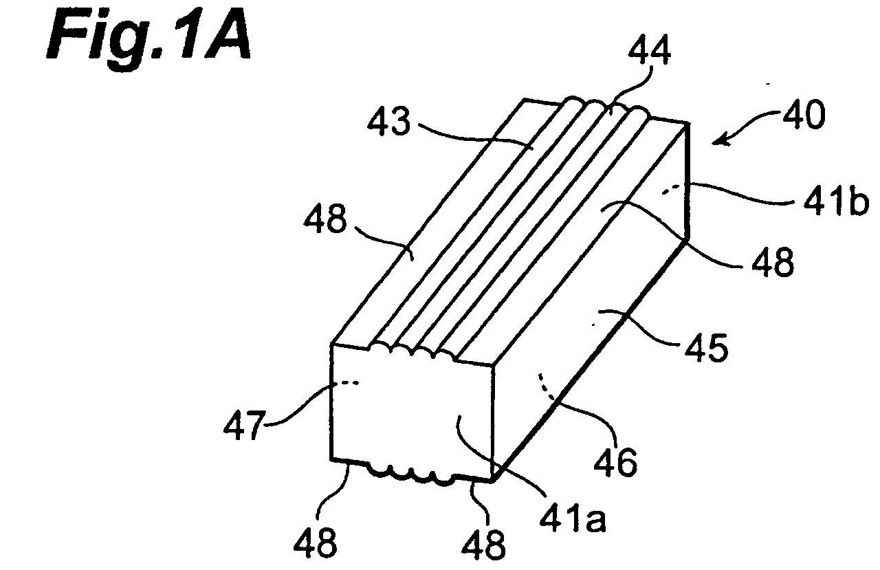
- the present invention provides an optical lens preform for drawing, the optical lens preform being constructed by a light-transparentmaterial into a columnar form comprising first to fourth side faces; at least one of the first side face and the third side face opposite from the first side face including a curved surface part formed parallel to a column axis, and a pair of flanges formed on both sides of the curved surface part.
- corner parts which are likely to deform under the influence of heating due to drawing are formed with a pair of flanges in such an optical lens preform, the pair of flanges are influencedby the heating, whereas each curved surface part acting as an optically effective part can be kept from being influenced.
- the "column axis of the columnar form” refers to a line segment passing the geometric center of gravity in each of the upper face 41a and bottom face 41b (see Fig. 1A) of the preform.
- the curved surface part may be constituted by a plurality of curved surface parts arranged in contact with each other.
- any cross section perpendicular to the column axis of the optical lens preform is oblong.
- the second and fourth side faces become parallel to each other, therebymaking it easier to carry out an optical lens arranging step which will be explained later.
- oblong refers to a form which is considered oblong if the first and third curved surfaces are assumed to be planar without taking account of the curved surface parts formed therein. For example, it encompasses the form indicated by the upper face 41a in Fig. 1A.
- the curved surface part may be formed as an aspheric surface.
- each flange has a projection protruded beyond the curved surface part.
- the optical lens preform when drawing the optical lens preform by a roller, the optical lens preform can stably be held by way of the projections of the pair of flanges, whereby the optical lens preform can be prevented from wobbling at the time of drawing.
- the optical lens made by drawing such an optical lens preform has projections corresponding to those of the preform, and thus can prevent curved surface parts from coming into direct contact with an arrangement surface on which the optical lens is disposed, side faces of members adjacent to the optical lens, and the like.
- curved surface parts acting on light are harder to damage and so forth, and performances of outgoing light are kept from lowering.
- At least one of the first and third side faces is formed into a convex surface.
- side faces thereof may be distorted so as to retract.
- Forming at least one of the first and third side faces into a convex surface can suppress the influence of distortion due to the drawing.
- the present invention provides a method of making an optical lens, the method comprising an optical lens preform producing step of producing the optical lens preform; a drawing step of drawing the optical lens preform produced by the optical lens preform producing step; and an optical lens producing step of producing an optical lens by cutting the optical lens preform drawn by the drawing step; wherein the curved surface part of the optical lens preform drawn by the drawing step functions as an optically effective part acting on incident light or outgoing light.
- the form of the optical lens in particular, can be determined in the stage of the preformbefore drawing, whereby the optically effective part can be processed in a sufficiently large size.
- “acting on light” refers to changing the angle of divergence or convergence of incident light and emitting thus changed light, or changing the optical path of the incident light.
- the optical lens producing step may include a flange cutting step of cutting off the pair of flanges from the optical lens produced by cutting the optical lens preform drawn by the drawing step. This realizes an optical lens having removed parts adversely affected by deformation and the like upon heating in the drawing step.
- the optical lens producing step may include an optical lens arranging step of preparing a plurality of optical lenses having the pair of flanges cut off by the flange cutting step, and arranging the optical lenses into an array by bonding the respective second and fourth side faces to each other. This realizes an optical lens comprising a number of curved surface parts. Also, since a pair of flanges are cut off from each of the individual optical lenses arranged, an optical lens having eliminated the adverse effects due to the heating in the drawing is realized.
- the drawing step carries out drawing by using heating means with an annular form surrounding the optical lens preform produced by the optical lens preform producing step, whereas the heating means comprises a ring form corresponding to a cross-sectional form in a cross section perpendicular to the column axis of the optical lens preform.
- the heating means comprises the ring form corresponding to the form of the optical lens preform, the heating temperature does not concentrate at corner parts of the optical lens preform.
- the "ring form corresponding to a cross-sectional form perpendicular to the column axis of the preform” refers to a form in which the distance from each side face of the preform to the heating means is the same as shown in Fig. 5B.
- optical lens in accordance with the present invention is produced by any of the above-mentioned methods of making an optical lens.
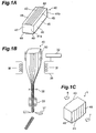
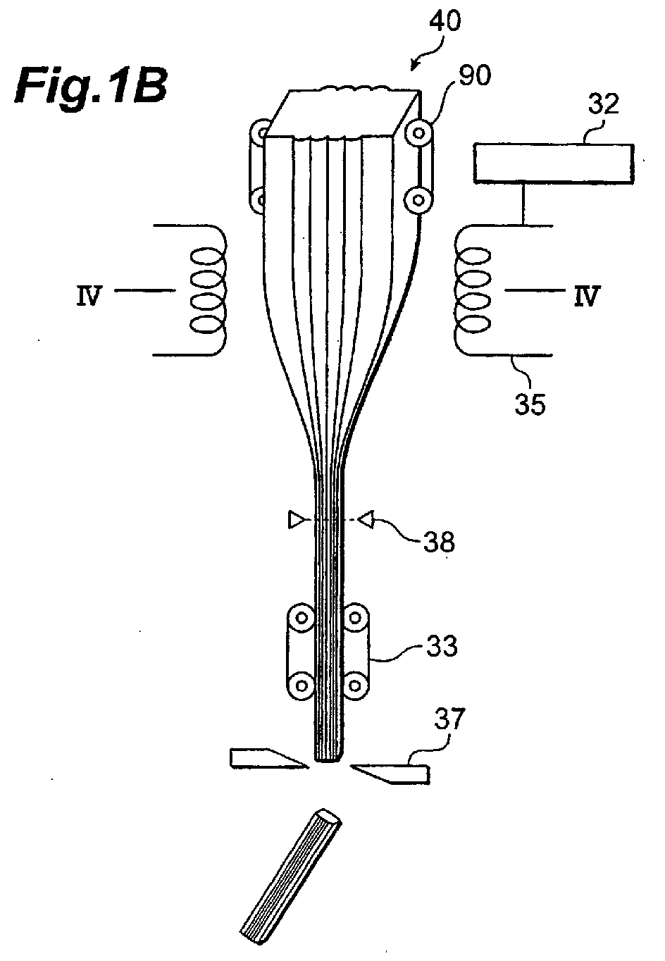
- Figs. 1A to 1C are schematic views showing respective steps in the method of making an optical lens in accordance with a first embodiment.
- an optical member made of a light-transparent glass material is initially prepared, and is shaped into a quadrangular prism comprising a first side face 44 to a fourth side face 47, thus forming an optical lens preform 40 (optical lens preform producing step).
- Any cross section perpendicular to the column axis of the optical lens preform 40 is in the same oblong form.
- first side face 44 and third side face 46 are parallel to each other
- second side face 45 and fourth side face 47 are parallel to each other
- first side face 44 and second side face 45 are at right angles
- third side face 46 and fourth side face 47 are at right angles.
- the first side face 44 and third side face 46 are formed with a plurality of curved surface parts 43, parallel to the column axis, in contact with each other.
- the plurality of curved surface parts 43 are convex surfaces, and function as an optically effective part acting on incident light or outgoing light after being drawn.
- the convex surfaces may be aspheric surfaces.
- Each of the first side face 44 and third side face 46 is further formed with a pair of flanges 48 on both sides of the plurality of curved surface parts 43 (at corner parts of the optical lens preform 40).
- the corner parts of the optical lens preform 40 are likely to deform and so forth under the influence of the heating in the drawing step, the plurality of curved surface parts 43 themselves are less likely to be influenced by the heating in the optical lens preform 40 in accordance with this embodiment, since the pair of flanges 48 are formed. This effect will be explained later.
- the form of an optical lens to be produced in particular, can be shaped in the stage of the optical lens preform 40 having a sufficiently large size (e.g., a width of 5 to 6 cm and a length of 20 cm), whereby these operations can be carried out in a simple and accurate manner.
- a sufficiently large size e.g., a width of 5 to 6 cm and a length of 20 cm
- Japanese Patent Publication No. HEI 7-15521 discloses a method of making a refractive index distribution type cylindrical lens (SELFOC lens) by drawing.
- This method employs, as a preform, a high-purity silica glass rod in which the fluorine dopant amount increases stepwise from the center to the radially outer side, so that the refractive index decreases stepwise accordingly, and does not use a preform formed with an optically effective part in terms of shape as in the present invention.
- the conventional method necessitates, as a step of producing a preform, a step of doping it with fluorine by outside plasma method or immersing it into a molten salt for a long time so as to effect ion exchange, thereby forming a refractive index distribution, such a step is unnecessary in the present invention.
- the conventional method is also different from the present invention in terms of the resulting optical lens 1 in that the light entrance and exit surfaces are not the curved surfaces of a cylindrical form and both end parts thereof are used.
- the optical lens preform 40 shaped by the optical lens preform producing step is melted upon heating by an electric furnace 35 or the like acting as heating means, and is drawn so as to attain a desirable diameter (drawing step).
- the electric furnace 35 has an annular form surrounding the optical lens preform 40, and evenly heats and melts the optical lens preform 40 from thereabout.
- a temperature regulator 32 is connected to the electric furnace 35, whereby the temperature of the electric furnace 35 can be changed so as to adjust the drawing temperature.
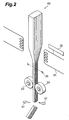
- Feeding rollers 90 and pulling rollers 33 are used for drawing and expanding the heated optical lens preform 40.
- the optical lens preform 40 can be prevented from twisting during drawing if the second side face 45 and fourth side face 47 are held by the feeding rollers 90 and pulling rollers 33.
- the optical lens preform 40 may be pulled by the pulling rollers 33 for drawing.
- the optical lens preform 40 is cut by a cutter 37 placed below the pulling rollers 33. This determination is carried out by a diameter meter 38 disposed upstream the pulling rollers 33.
- the diameter meter 38 comprises a laser section for emitting laser light, a light-receiving section for receiving the laser light transmitted through the optical lens preform 40, and an analyzing section for calculating the outer diameter of the optical lens preform 40 from the quantity of light received by the light-receiving section and the like.
- the optical lens formed by cutting with the cutter 37 has a rod shape with a length of 5 mm to 2000 mm, which may be in a size employed as an optical lens or a size in a stage before being cut or shaved into a desirable length (optical lens producing step).
- the optical lens is likely to break when too long, and is inconvenient for cutting and shaving when too short.
- the drawn product is wound about a drum or the like when making an optical fiber or the like, the making of an optical lens is characterized by cutting the drawn product as such.
- optical lens 1 has a cross-sectional form identical to that of the optical lens preform 40 because of characteristics of drawing.
- the optical lens the optically effective parts 43 constituted by a convex surface in particular, is not subjected to shaping except for cutting into a desirable length and grinding on the outer periphery, whereby the burden on manufacture can be alleviated.
- incident light 6 is collimated or converged by the optically effective parts 43 (curved surface parts 43 in the preform stage) formed on the light entrance side and light exit side, and thus collimated or converged light is emitted as outgoing light 7.
- the directions of the incident light 6 and outgoing light 7 may be reversed.
- optical lens 1 comprising four curved surfaces as the optically effective part 43 is formed in this embodiment, light beams emitted from a semiconductor laser array acting as a light-emitting device having four light-emitting parts arranged therein can be collimated or converged, for example, and thus collimated or converged light beams can be emitted.
- Figs. 3A and 3B are schematic views showing respective steps in the method of making an optical lens in accordance with a second embodiment. These steps follow those of Figs. 1A to 1C.
- the pair of flanges 48 are initially cut off from the optical lens 1 produced in Fig. 1C (flange cutting step), so as to yield an optical lens 21.
- the flanges 48 incur (or may incur) influences such as deformation upon heating in the drawing step. Therefore, cutting off such a pair of flanges 48 realizes an optical lens which is more compact than the optical lens 1 shown in Fig. 1C and free of adverse effects (such as deformation) upon heating.
- the optically effective part 43 comprises four convex surfaces 43, whereby respective light beams emitted from four light-emitting parts arranged in a light-emitting device can be converged or collimated, and thus converged or collimated light beams can be emitted.
- a plurality of optical lenses 21 each having cut off the pair of flanges 48 as shown in Fig. 3A may be prepared and arranged into an array by bonding their second side faces 45 and fourth side faces 47 to each other (optical lens arranging step). Since the flanges 48 have already been cut by the flange cutting step, an optical lens 31 having curved surfaces arranged with the same pitch width is formed by simply arranging the plurality of optical lenses 21 while bringing their side faces into contact with each other (and bonding them). Since the adverse effects (such as deformation) upon heating in the drawing step are eliminated at the point of the optical lens 21, thus formed optical lens 31 is also free of the adverse effects upon heating in the drawing step.
- Figs. 4A and 4B are views showing effects of the methods of making an optical lens in accordance with the first and second embodiments.
- Fig. 4A shows an optical lens preform 140 in accordance with a comparative example, and a cross section of an optical lens 101 produced by drawing from the optical lens preform 140.
- Fig. 4B shows the optical lens preform 40 in accordance with the embodiments, and a cross section of the optical lens 1 produced by drawing from the optical lens preform 40.
- the optical lens preform 140 in accordance with the comparative lens has no flange. Heating is likely to concentrate at corner parts 49 of the preform, thus yielding a high temperature. Therefore, upon drawing, the curved surface parts 43 located at the corner parts 49 are deformed under the influence of the heating temperature. Thus deformed curved surface parts 43 do not function as an optically effective part as intended in the designing stage.
- a pair of flanges 48 are formed on both sides of the plurality of curved surface parts 43, i.e., at corner parts 49 of the optical lens preform 40 in the methods of making an optical lens in accordance with the embodiments.
- the pair of flanges 48 deform under the influence of heating in the drawing step, whereby the form of curved surface parts 43 is kept even after the drawing.
- a pair of flanges 48 are provided, so as to receive adverse effects due to the heating at the time of the drawing step, thereby protecting the plurality of curved surface parts 43, which will function as optically effective parts after the drawing. Therefore, it is not necessary for the flanges 48 to have a flat form.
- curved surface parts 43 formed in excess may be employed as flanges 48 to be cut off when affected by the heating upon drawing.
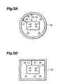
- Fig. 5A is a schematic sectional view of the drawing step in the method of making an optical lens in accordance with the first embodiment
- Fig. 5B is a schematic sectional view of the drawing step in the method of making an optical lens in accordance with a third embodiment
- Fig. 5A is also a sectional view taken along the line IV-IV of Fig. 1B.
- the electric furnace 35 acting as the heating means is formed like a ring surrounding the optical lens preform 40, and the ring is circular. Therefore, the distance 71 from each corner part 49 to the electric furnace 35 is shorter than the distance 70 from each curved surface part 43 to the electric furnace 35. Such a shorter distance to the electric furnace acting as a heat source may cause the corner parts 49 to attain a temperature higher than that of other parts, thereby deforming the corner parts 49 of the optical lens preform 40.
- the electric furnace 135 acting as the heating means has a form corresponding to the cross-sectional form of the optical lens preform 40, i.e., such a form that the side faces 44 to 47 of the optical lens preform 40 have the same distance to the electric furnace 135 at any parts, at the corners 49 inparticular (the distance in this case referring to the shortest distance to the electric furnace 135 without taking account of the curved surface parts 43 formed in the first side face 44 and third side face 46).
- the electric furnace 135 having such a form is further effective when the optical lens preform 40 has a horizontal size longer than the vertical size thereof.
- the present invention is specifically explained in the foregoing with reference to the first to third embodiments, the present invention is not limited to the embodiments, which merely illustrate the best modes for carrying out the invention, but includes all the alterations of the invention falling within the scope of claims of the invention and can be modified in terms of form, size, arrangement, and the like.
- single curved surfaces 343, 443, 543 may be provided.
- the flanges may have projections 348, 448 protruded from the curved surface parts 343, 443 as shown in Figs. 6A, 6B.
- the optical lens preforms 340, 440 can stably be held by the rollers 33 by way of a pair of projections 348, 448, and thus can be prevented from wobbling at the time of drawing.
- the rollers 33 and the curved surface parts can be kept from interfering with each other.
- the optical lenses 301, 401 made by drawing such optical lens preforms 340, 440 have protrusions corresponding to the projections 348, 448 of the preforms 340, 440, the curved surface parts 343, 443 can be prevented from coming into direct contact with an arrangement surface on which the optical lenses 301, 401 are disposed, side faces of members adjacent to the optical lenses 301, 401, and the like. This makes the curved surface parts 343, 443, which act on light, harder to damage and so forth, and prevents performances of outgoing light from deteriorating.
- the curved surface part 443 shown in Fig. 6B may be provided on one side alone.
- Figs. 6A to 6C show respective optical lenses 301, 401, 501 formed by drawing the optical lens preforms 340, 440, 540 shown on the left side.
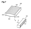
- each of the first side face 644 and third side face 646 as a whole may be formed into a convex surface.
- each of the first side face 644 and third side face 646 comprises a plurality of curved surface parts
- each of the first side face 644 and third side face 646 is considered to be in a convex surface form if a surface in contact with all of the plurality of curved surface parts is a convex surface.
- flat surface parts (first to fourth side faces) of an optical lens preform may deform to retract upon drawing, forming the first side face 644 and third side face 646 into a convex surface beforehand yields an optical lens 601 (on the right side of Fig. 7) having eliminated the distortion due to the drawing.
- the flanges of the optical lens preform shown in Fig. 7 also have projections 648 protruded from the curved surface parts. Therefore, when drawn as shown in Fig. 2, the rollers 33 can stably hold the optical lens preform 640 by way of a pair of projections 648, whereby the optical lens preform 640 can be prevented from wobbling at the time of drawing. Also, the rollers 33 and the curved surface parts can be prevented from interfering with each other.
- the optical lens 601 made by drawing such an optical lens preform 640 has projections corresponding to the projections 648 of the preform 640, and thus can prevent the curved surface parts from coming into direct contact with an arrangement surface on which the optical lens 601 is disposed, side faces of members adjacent to the optical lens 601, or the like. As a consequence, curved surface parts acting on light are harder to damage and so forth, and performances of outgoing light are kept from lowering.
- the form of the optical lens, the form of the optically effective part in particular can be determined in the stage of the preform before drawing, whereby the optically effective part can be processed in a sufficiently large size, and the form of the optical lens, the form of the optically effective part in particular, can easily be shaped.
- This realizes an optical lens having an optically effective part accurately acting on light. Also, the burden on manufacture can be alleviated.
- corner parts which are likely to be influenced by heating in the drawing step so as to deform and so forth are formed with flanges, whereby each curved surface part acting as an optically effective part can be kept from being influenced by heating. This realizes an optical lens whose optically effective part is not deformed by the drawing step.
Landscapes
- Physics & Mathematics (AREA)
- General Physics & Mathematics (AREA)
- Optics & Photonics (AREA)
- Chemical & Material Sciences (AREA)
- Engineering & Computer Science (AREA)
- Materials Engineering (AREA)
- Organic Chemistry (AREA)
- Manufacturing & Machinery (AREA)
- Eyeglasses (AREA)
- Re-Forming, After-Treatment, Cutting And Transporting Of Glass Products (AREA)
Abstract
Description
Claims (11)
- An optical lens preform for drawing, the optical lens preform being constructed by a light-transparent material into a columnar form comprising first to fourth side faces;
at least one of the first side face and the third side face opposite from the first side face including a curved surface part formed parallel to a column axis, and a pair of flanges formed on both sides of the curved surface part. - An optical lens preform according to claim 1, wherein the curved surface part is constituted by a plurality of curved surface parts arranged in contact with each other.
- An optical lens preform according to claim 1 or 2, wherein any cross section perpendicular to the column axis of the optical lens preform is oblong.
- An optical lens preform according to one of claims 1 to 3, wherein the curved surface part is formed as an aspheric surface.
- An optical lens preform according to one of claims 1 to 4, wherein the flange has a projection protruded beyond the curved surface part.
- An optical lens preform according to one of claims 1 to 5, wherein at least one of the first and third side faces is formed into a convex surface.
- A method of making an optical lens, the method comprising:wherein the curved surface part of the optical lens preform drawn by the drawing step functions as an optically effective part acting on incident light or outgoing light.an optical lens preform producing step of producing the optical lens preform according to one of claims 1 to 6;a drawing step of drawing the optical lens preform produced by the optical lens preform producing step; andan optical lens producing step of producing an optical lens by cutting the optical lens preform drawn by the drawing step;
- A method of making an optical lens according to claim 7, wherein the optical lens producing step includes a flange cutting step of cutting off the pair of flanges from the optical lens produced by cutting the optical lens preform drawn by the drawing step.
- A method of making an optical lens according to claim 8, wherein the optical lens producing step includes an optical lens arranging step of preparing a plurality of optical lenses having the pair of flanges cut off by the flange cutting step, and arranging the optical lenses into an array by bonding the respective second and fourth side faces to each other.
- A method of making an optical lens according to one of claims 7 to 9, wherein the drawing step carries out drawing by using heating means with an annular form surrounding the optical lens preform produced by the optical lens preform producing step, the heating means comprising a ring form corresponding to a cross-sectional form in a cross section perpendicular to the column axis of the optical lens preform.
- An optical lens produced by the method of making an optical lens according to one of claims 7 to 10.
Applications Claiming Priority (5)
| Application Number | Priority Date | Filing Date | Title |
|---|---|---|---|
| JP2001139220 | 2001-05-09 | ||
| JP2001139228 | 2001-05-09 | ||
| JP2001139220 | 2001-05-09 | ||
| JP2001139228 | 2001-05-09 | ||
| PCT/JP2002/004497 WO2002091037A1 (en) | 2001-05-09 | 2002-05-08 | Optical lens-use base material, optical lens, and method of producing optical lens |
Publications (3)
| Publication Number | Publication Date |
|---|---|
| EP1396735A1 true EP1396735A1 (en) | 2004-03-10 |
| EP1396735A4 EP1396735A4 (en) | 2007-05-23 |
| EP1396735B1 EP1396735B1 (en) | 2009-01-28 |
Family
ID=26614846
Family Applications (1)
| Application Number | Title | Priority Date | Filing Date |
|---|---|---|---|
| EP02769099A Expired - Lifetime EP1396735B1 (en) | 2001-05-09 | 2002-05-08 | Method of producing an optical lens |
Country Status (7)
| Country | Link |
|---|---|
| US (2) | US6947226B2 (en) |
| EP (1) | EP1396735B1 (en) |
| JP (1) | JP4197957B2 (en) |
| KR (1) | KR100906045B1 (en) |
| CN (2) | CN1789186B (en) |
| DE (1) | DE60231037D1 (en) |
| WO (1) | WO2002091037A1 (en) |
Cited By (1)
| Publication number | Priority date | Publication date | Assignee | Title |
|---|---|---|---|---|
| WO2006018167A1 (en) * | 2004-08-17 | 2006-02-23 | Hentze-Lissotschenko Patentverwaltungs Gmbh & Co. Kg | Device for homogenizing light and method for the production of said device |
Families Citing this family (10)
| Publication number | Priority date | Publication date | Assignee | Title |
|---|---|---|---|---|
| WO2002091037A1 (en) * | 2001-05-09 | 2002-11-14 | Hamamatsu Photonics K.K. | Optical lens-use base material, optical lens, and method of producing optical lens |
| US20040163420A1 (en) * | 2003-01-06 | 2004-08-26 | Dowd Edward Michael | Method of fusing and stretching a large diameter optical waveguide |
| JP5017798B2 (en) * | 2005-04-20 | 2012-09-05 | コニカミノルタアドバンストレイヤー株式会社 | Molding device for molding shaping element used for pickup optical system and shaping element manufactured by the device |
| JP2009294236A (en) * | 2006-09-28 | 2009-12-17 | Mitsubishi Electric Corp | Array type optical component, method for manufacturing the same and optical system for array type semiconductor laser |
| US8377249B2 (en) | 2009-04-03 | 2013-02-19 | The Procter & Gamble Company | Appraratus and method for providing a localized speed variance of an advancing substrate |
| PL224044B1 (en) * | 2011-07-13 | 2016-11-30 | Doros Teodora D A Glass | Method for obtaining a homogeneous beam of electromagnetic radiation of any geometrical shape and the mechanical-optical device to apply this method |
| US9144624B2 (en) | 2013-07-19 | 2015-09-29 | The Procter & Gamble Company | Method for providing a localized dwell in an advancing web |
| CN105044863B (en) * | 2014-02-10 | 2017-03-08 | 青岛海信宽带多媒体技术有限公司 | Optical assembly |
| JP6790620B2 (en) * | 2016-09-07 | 2020-11-25 | 富士ゼロックス株式会社 | Manufacturing method of molded products, manufacturing method of optical members |
| USD984532S1 (en) | 2021-02-03 | 2023-04-25 | One Five Three Enterprises Llc | Learning standing tower with reversible white and black board |
Family Cites Families (42)
| Publication number | Priority date | Publication date | Assignee | Title |
|---|---|---|---|---|
| JPS57145040A (en) | 1981-03-02 | 1982-09-07 | Nippon Telegr & Teleph Corp <Ntt> | Production of rod lens |
| JPS57169706A (en) | 1981-04-13 | 1982-10-19 | Nippon Telegr & Teleph Corp <Ntt> | Production of diffraction grating |
| JPS5938562B2 (en) | 1981-04-14 | 1984-09-18 | 日本電信電話株式会社 | optical fiber |
| JPS57175739A (en) | 1981-04-17 | 1982-10-28 | Nippon Telegr & Teleph Corp <Ntt> | Preparation of rod lens |
| JPS57181516A (en) | 1981-05-01 | 1982-11-09 | Agency Of Ind Science & Technol | Heterogeneous refractive index lens |
| JPS57183328A (en) | 1981-05-06 | 1982-11-11 | Nippon Telegr & Teleph Corp <Ntt> | Production of flat plate lens |
| GB2108483B (en) * | 1981-10-29 | 1985-05-30 | Standard Telephones Cables Ltd | Glass drawing |
| JPS58168026A (en) | 1982-03-29 | 1983-10-04 | Agency Of Ind Science & Technol | Embedded type spherical lens having distributed refractive index |
| JPS5992935A (en) | 1982-11-18 | 1984-05-29 | Hitachi Cable Ltd | Preparation of optical fiber having maintained plane of polarization |
| GB8606838D0 (en) * | 1986-03-19 | 1986-04-23 | Combined Optical Ind Ltd | Lens |
| DE3617363A1 (en) | 1986-05-23 | 1987-11-26 | Schott Glaswerke | METHOD FOR THE PRODUCTION OF CYLINDRICAL SYMMETRICAL BODIES WITH PRESET RADIAL FALLING PHYSICAL MATERIAL PROPERTIES AND APPLICATIONS |
| JPH0725565B2 (en) | 1986-06-27 | 1995-03-22 | 日本電信電話株式会社 | Optical fiber drawing device |
| US5004328A (en) | 1986-09-26 | 1991-04-02 | Canon Kabushiki Kaisha | Spherical lens and imaging device using the same |
| US5155631A (en) | 1990-10-01 | 1992-10-13 | The United States Of America As Represented By The Department Of Energy | Method for fabrication of cylindrical microlenses of selected shape |
| US5080706A (en) | 1990-10-01 | 1992-01-14 | The United States Of America As Represented By The Department Of Energy | Method for fabrication of cylindrical microlenses of selected shape |
| US5081639A (en) | 1990-10-01 | 1992-01-14 | The United States Of America As Represented By The United States Department Of Energy | Laser diode assembly including a cylindrical lens |
| US5293269A (en) * | 1991-05-03 | 1994-03-08 | Mcdonnell Douglas Corporation | Aspheric cylindrical lens and method of fabrication |
| FR2687920B1 (en) | 1992-02-27 | 1994-05-06 | Taylor Made Golf Cy Inc | IMPROVEMENT FOR GOLF CLUB HEAD AND METHODS FOR MAKING SAME. |
| JPH062311U (en) * | 1992-06-15 | 1994-01-14 | 株式会社三協精機製作所 | Lens mounting structure |
| JPH0742683B2 (en) | 1992-06-18 | 1995-05-10 | 信号器材株式会社 | New / recycled road marking application method and device |
| US5450244A (en) * | 1992-12-18 | 1995-09-12 | Polaroid Corporation | Cylindrical fiber coupling lens with biaspheric surfaces |
| US5513201A (en) | 1993-04-30 | 1996-04-30 | Nippon Steel Corporation | Optical path rotating device used with linear array laser diode and laser apparatus applied therewith |
| JP3071360B2 (en) | 1993-04-30 | 2000-07-31 | 新日本製鐵株式会社 | Optical path converter used for linear array laser diode, laser device using the same, and method of manufacturing the same |
| JPH0715521A (en) | 1993-06-23 | 1995-01-17 | Toshiba Corp | Phone system |
| JPH07287104A (en) | 1994-04-18 | 1995-10-31 | Nippon Steel Corp | Optical path changing device and optical path changing array |
| JPH07291651A (en) | 1994-04-26 | 1995-11-07 | Hoya Corp | Soluble core glass for microchannel plate manufacturing |
| US5596671A (en) * | 1994-04-28 | 1997-01-21 | Rockwell, Iii; Marshall A. | Optical waveguide display system |
| DE69616835T2 (en) | 1995-07-04 | 2002-04-11 | Hamamatsu Photonics K.K., Hamamatsu | Fiber optic plate |
| JP3692512B2 (en) | 1995-10-25 | 2005-09-07 | 日本電気硝子株式会社 | Crystalline glass stretch molding equipment |
| DE19610881B4 (en) | 1995-12-07 | 2008-01-10 | Limo Patentverwaltung Gmbh & Co. Kg | Microsystem module |
| JPH101321A (en) | 1996-06-18 | 1998-01-06 | Hooya Precision Kk | Optical element manufacturing method |
| US5790576A (en) | 1996-06-26 | 1998-08-04 | Sdl, Inc. | High brightness laser diode source |
| JP4019443B2 (en) | 1996-09-19 | 2007-12-12 | コニカミノルタホールディングス株式会社 | Inspection device and method for assembling inspection device |
| US5745519A (en) | 1996-11-12 | 1998-04-28 | Opto Power Corp. | Laser diode system |
| JPH10245236A (en) | 1996-12-26 | 1998-09-14 | Hoya Corp | Glass forming preform and method for manufacturing optical fiber fixing member using the same |
| US5867327A (en) | 1997-04-23 | 1999-02-02 | Blue Sky Research | Process for manufacturing cylindrical microlenses |
| DE19819333A1 (en) * | 1998-04-30 | 1999-11-04 | Lissotschenko Vitaly | Optical emitter array with collimation optics |
| JP4080608B2 (en) * | 1998-09-25 | 2008-04-23 | 浜松ホトニクス株式会社 | Semiconductor laser light source device |
| EP1006382B1 (en) | 1998-10-30 | 2002-09-18 | Lissotschenko, Vitalij | Apparatus and device for optically converting a light beam |
| AU1306901A (en) | 1999-11-10 | 2001-06-06 | Hamamatsu Photonics K.K. | Optical lens and optical system |
| CN100471804C (en) | 2001-05-09 | 2009-03-25 | 浜松光子学株式会社 | Base material for optical lens, and method for manufacturing optical lens |
| WO2002091037A1 (en) * | 2001-05-09 | 2002-11-14 | Hamamatsu Photonics K.K. | Optical lens-use base material, optical lens, and method of producing optical lens |
-
2002
- 2002-05-08 WO PCT/JP2002/004497 patent/WO2002091037A1/en not_active Ceased
- 2002-05-08 US US10/476,866 patent/US6947226B2/en not_active Expired - Lifetime
- 2002-05-08 EP EP02769099A patent/EP1396735B1/en not_active Expired - Lifetime
- 2002-05-08 KR KR1020037014409A patent/KR100906045B1/en not_active Expired - Fee Related
- 2002-05-08 DE DE60231037T patent/DE60231037D1/de not_active Expired - Lifetime
- 2002-05-08 JP JP2002588241A patent/JP4197957B2/en not_active Expired - Fee Related
- 2002-05-08 CN CN2005101247040A patent/CN1789186B/en not_active Expired - Fee Related
- 2002-05-08 CN CNB028094948A patent/CN1279372C/en not_active Expired - Fee Related
-
2005
- 2005-09-12 US US11/223,035 patent/US7110193B2/en not_active Expired - Lifetime
Cited By (4)
| Publication number | Priority date | Publication date | Assignee | Title |
|---|---|---|---|---|
| WO2006018167A1 (en) * | 2004-08-17 | 2006-02-23 | Hentze-Lissotschenko Patentverwaltungs Gmbh & Co. Kg | Device for homogenizing light and method for the production of said device |
| US7414789B2 (en) | 2004-08-17 | 2008-08-19 | Limo-Patentverwaltung Gmbh & Co. Kg | Apparatus for homogenizing light and method for producing the apparatus |
| RU2362193C2 (en) * | 2004-08-17 | 2009-07-20 | Лимо Патентфервальтунг Гмбх Унд Ко.Кг | Light homogenisation device and method of its fabrication |
| CN100516934C (en) * | 2004-08-17 | 2009-07-22 | Limo专利管理有限及两合公司 | Apparatus for homogenizing light and method for producing the apparatus |
Also Published As
| Publication number | Publication date |
|---|---|
| US7110193B2 (en) | 2006-09-19 |
| WO2002091037A1 (en) | 2002-11-14 |
| JPWO2002091037A1 (en) | 2004-08-26 |
| US6947226B2 (en) | 2005-09-20 |
| CN1507569A (en) | 2004-06-23 |
| CN1789186B (en) | 2010-11-17 |
| KR20030096352A (en) | 2003-12-24 |
| EP1396735B1 (en) | 2009-01-28 |
| KR100906045B1 (en) | 2009-07-03 |
| DE60231037D1 (en) | 2009-03-19 |
| US20040130791A1 (en) | 2004-07-08 |
| EP1396735A4 (en) | 2007-05-23 |
| JP4197957B2 (en) | 2008-12-17 |
| US20060007555A1 (en) | 2006-01-12 |
| CN1279372C (en) | 2006-10-11 |
| CN1789186A (en) | 2006-06-21 |
Similar Documents
| Publication | Publication Date | Title |
|---|---|---|
| US6947226B2 (en) | Optical lens-use base material, optical lens, and method of producing optical lens | |
| US20060045444A1 (en) | Fiber bundles and methods of making fiber bundles | |
| US6094515A (en) | Optical module | |
| TW201617659A (en) | Optical assembly and method for producing and using the same | |
| EP1386888B1 (en) | Production method for optical lens by drawing | |
| JP7197354B2 (en) | LENS UNIT AND METHOD OF MANUFACTURING LENS UNIT | |
| US7833089B2 (en) | Optical lens preform, optical lens, and method of making optical lens | |
| EP1394572B1 (en) | Method of producing optical lens, and optical lens | |
| JPH0854538A (en) | Manufacturing method of optical fiber terminal with microlens | |
| US11860377B2 (en) | Device for emitting light | |
| KR100902455B1 (en) | Manufacturing method of the optical lens | |
| JP4841742B2 (en) | Manufacturing method of optical lens |
Legal Events
| Date | Code | Title | Description |
|---|---|---|---|
| PUAI | Public reference made under article 153(3) epc to a published international application that has entered the european phase |
Free format text: ORIGINAL CODE: 0009012 |
|
| 17P | Request for examination filed |
Effective date: 20031201 |
|
| AK | Designated contracting states |
Kind code of ref document: A1 Designated state(s): AT BE CH CY DE DK ES FI FR GB GR IE IT LI LU MC NL PT SE TR |
|
| AX | Request for extension of the european patent |
Extension state: AL LT LV MK RO SI |
|
| A4 | Supplementary search report drawn up and despatched |
Effective date: 20070419 |
|
| 17Q | First examination report despatched |
Effective date: 20070709 |
|
| RTI1 | Title (correction) |
Free format text: METHOD OF PRODUCING AN OPTICAL LENS |
|
| GRAP | Despatch of communication of intention to grant a patent |
Free format text: ORIGINAL CODE: EPIDOSNIGR1 |
|
| GRAS | Grant fee paid |
Free format text: ORIGINAL CODE: EPIDOSNIGR3 |
|
| GRAA | (expected) grant |
Free format text: ORIGINAL CODE: 0009210 |
|
| AK | Designated contracting states |
Kind code of ref document: B1 Designated state(s): DE FR GB |
|
| REG | Reference to a national code |
Ref country code: GB Ref legal event code: FG4D |
|
| REF | Corresponds to: |
Ref document number: 60231037 Country of ref document: DE Date of ref document: 20090319 Kind code of ref document: P |
|
| PLBE | No opposition filed within time limit |
Free format text: ORIGINAL CODE: 0009261 |
|
| STAA | Information on the status of an ep patent application or granted ep patent |
Free format text: STATUS: NO OPPOSITION FILED WITHIN TIME LIMIT |
|
| 26N | No opposition filed |
Effective date: 20091029 |
|
| REG | Reference to a national code |
Ref country code: FR Ref legal event code: PLFP Year of fee payment: 15 |
|
| REG | Reference to a national code |
Ref country code: FR Ref legal event code: PLFP Year of fee payment: 16 |
|
| REG | Reference to a national code |
Ref country code: FR Ref legal event code: PLFP Year of fee payment: 17 |
|
| PGFP | Annual fee paid to national office [announced via postgrant information from national office to epo] |
Ref country code: DE Payment date: 20200428 Year of fee payment: 19 Ref country code: FR Payment date: 20200414 Year of fee payment: 19 |
|
| PGFP | Annual fee paid to national office [announced via postgrant information from national office to epo] |
Ref country code: GB Payment date: 20200430 Year of fee payment: 19 |
|
| REG | Reference to a national code |
Ref country code: DE Ref legal event code: R119 Ref document number: 60231037 Country of ref document: DE |
|
| GBPC | Gb: european patent ceased through non-payment of renewal fee |
Effective date: 20210508 |
|
| PG25 | Lapsed in a contracting state [announced via postgrant information from national office to epo] |
Ref country code: GB Free format text: LAPSE BECAUSE OF NON-PAYMENT OF DUE FEES Effective date: 20210508 Ref country code: DE Free format text: LAPSE BECAUSE OF NON-PAYMENT OF DUE FEES Effective date: 20211201 |
|
| PG25 | Lapsed in a contracting state [announced via postgrant information from national office to epo] |
Ref country code: FR Free format text: LAPSE BECAUSE OF NON-PAYMENT OF DUE FEES Effective date: 20210531 |