EP1396730B1 - Method, system and apparatus for detecting a position of a terminal in a network - Google Patents
Method, system and apparatus for detecting a position of a terminal in a network Download PDFInfo
- Publication number
- EP1396730B1 EP1396730B1 EP20030013374 EP03013374A EP1396730B1 EP 1396730 B1 EP1396730 B1 EP 1396730B1 EP 20030013374 EP20030013374 EP 20030013374 EP 03013374 A EP03013374 A EP 03013374A EP 1396730 B1 EP1396730 B1 EP 1396730B1
- Authority
- EP
- European Patent Office
- Prior art keywords
- base stations
- terminal
- clock
- base station
- server
- Prior art date
- Legal status (The legal status is an assumption and is not a legal conclusion. Google has not performed a legal analysis and makes no representation as to the accuracy of the status listed.)
- Expired - Lifetime
Links
- 238000000034 method Methods 0.000 title claims description 52
- 238000004891 communication Methods 0.000 claims description 64
- 230000005540 biological transmission Effects 0.000 claims description 41
- 238000012545 processing Methods 0.000 claims description 9
- 230000004044 response Effects 0.000 claims description 2
- 230000014509 gene expression Effects 0.000 description 49
- 230000006870 function Effects 0.000 description 30
- 238000005259 measurement Methods 0.000 description 29
- 238000012546 transfer Methods 0.000 description 13
- 238000010586 diagram Methods 0.000 description 5
- 230000008859 change Effects 0.000 description 4
- 230000001360 synchronised effect Effects 0.000 description 4
- 238000004364 calculation method Methods 0.000 description 3
- 238000001514 detection method Methods 0.000 description 3
- 238000012544 monitoring process Methods 0.000 description 3
- 108700026140 MAC combination Proteins 0.000 description 2
- 108010076504 Protein Sorting Signals Proteins 0.000 description 2
- 230000001934 delay Effects 0.000 description 2
- 230000003287 optical effect Effects 0.000 description 2
- 230000008569 process Effects 0.000 description 2
- 230000008054 signal transmission Effects 0.000 description 2
- 238000012935 Averaging Methods 0.000 description 1
- 238000005266 casting Methods 0.000 description 1
- 230000015556 catabolic process Effects 0.000 description 1
- 238000004590 computer program Methods 0.000 description 1
- 238000012937 correction Methods 0.000 description 1
- 238000013500 data storage Methods 0.000 description 1
- 238000006731 degradation reaction Methods 0.000 description 1
- 238000005516 engineering process Methods 0.000 description 1
- 239000000543 intermediate Substances 0.000 description 1
- 230000007246 mechanism Effects 0.000 description 1
- 238000012986 modification Methods 0.000 description 1
- 230000004048 modification Effects 0.000 description 1
- 238000001228 spectrum Methods 0.000 description 1
Images


Classifications
-
- H—ELECTRICITY
- H04—ELECTRIC COMMUNICATION TECHNIQUE
- H04W—WIRELESS COMMUNICATION NETWORKS
- H04W64/00—Locating users or terminals or network equipment for network management purposes, e.g. mobility management
-
- G—PHYSICS
- G01—MEASURING; TESTING
- G01S—RADIO DIRECTION-FINDING; RADIO NAVIGATION; DETERMINING DISTANCE OR VELOCITY BY USE OF RADIO WAVES; LOCATING OR PRESENCE-DETECTING BY USE OF THE REFLECTION OR RERADIATION OF RADIO WAVES; ANALOGOUS ARRANGEMENTS USING OTHER WAVES
- G01S5/00—Position-fixing by co-ordinating two or more direction or position line determinations; Position-fixing by co-ordinating two or more distance determinations
- G01S5/02—Position-fixing by co-ordinating two or more direction or position line determinations; Position-fixing by co-ordinating two or more distance determinations using radio waves
- G01S5/0205—Details
- G01S5/0221—Receivers
- G01S5/02213—Receivers arranged in a network for determining the position of a transmitter
- G01S5/02216—Timing or synchronisation of the receivers
-
- G—PHYSICS
- G01—MEASURING; TESTING
- G01S—RADIO DIRECTION-FINDING; RADIO NAVIGATION; DETERMINING DISTANCE OR VELOCITY BY USE OF RADIO WAVES; LOCATING OR PRESENCE-DETECTING BY USE OF THE REFLECTION OR RERADIATION OF RADIO WAVES; ANALOGOUS ARRANGEMENTS USING OTHER WAVES
- G01S5/00—Position-fixing by co-ordinating two or more direction or position line determinations; Position-fixing by co-ordinating two or more distance determinations
- G01S5/02—Position-fixing by co-ordinating two or more direction or position line determinations; Position-fixing by co-ordinating two or more distance determinations using radio waves
- G01S5/06—Position of source determined by co-ordinating a plurality of position lines defined by path-difference measurements
-
- G—PHYSICS
- G01—MEASURING; TESTING
- G01S—RADIO DIRECTION-FINDING; RADIO NAVIGATION; DETERMINING DISTANCE OR VELOCITY BY USE OF RADIO WAVES; LOCATING OR PRESENCE-DETECTING BY USE OF THE REFLECTION OR RERADIATION OF RADIO WAVES; ANALOGOUS ARRANGEMENTS USING OTHER WAVES
- G01S5/00—Position-fixing by co-ordinating two or more direction or position line determinations; Position-fixing by co-ordinating two or more distance determinations
- G01S5/0009—Transmission of position information to remote stations
- G01S5/0045—Transmission from base station to mobile station
- G01S5/0054—Transmission from base station to mobile station of actual mobile position, i.e. position calculation on base station
-
- G—PHYSICS
- G01—MEASURING; TESTING
- G01S—RADIO DIRECTION-FINDING; RADIO NAVIGATION; DETERMINING DISTANCE OR VELOCITY BY USE OF RADIO WAVES; LOCATING OR PRESENCE-DETECTING BY USE OF THE REFLECTION OR RERADIATION OF RADIO WAVES; ANALOGOUS ARRANGEMENTS USING OTHER WAVES
- G01S5/00—Position-fixing by co-ordinating two or more direction or position line determinations; Position-fixing by co-ordinating two or more distance determinations
- G01S5/0009—Transmission of position information to remote stations
- G01S5/0081—Transmission between base stations
-
- G—PHYSICS
- G01—MEASURING; TESTING
- G01S—RADIO DIRECTION-FINDING; RADIO NAVIGATION; DETERMINING DISTANCE OR VELOCITY BY USE OF RADIO WAVES; LOCATING OR PRESENCE-DETECTING BY USE OF THE REFLECTION OR RERADIATION OF RADIO WAVES; ANALOGOUS ARRANGEMENTS USING OTHER WAVES
- G01S5/00—Position-fixing by co-ordinating two or more direction or position line determinations; Position-fixing by co-ordinating two or more distance determinations
- G01S5/02—Position-fixing by co-ordinating two or more direction or position line determinations; Position-fixing by co-ordinating two or more distance determinations using radio waves
- G01S5/0205—Details
- G01S5/021—Calibration, monitoring or correction
Definitions
- the present invention generally relates to a position locating method employed for wireless communications and, more particularly, to a position locating method for wireless local area network (LAN) systems.
- LAN local area network
- the wireless LAN defined typically by the IEEE802.11 Standard is now employed widely in offices and public spaces such as hot spots due to its properties of compatibility with the Internet and fast data transfer with wide-ranged wireless media (semi-micro waves, semi-millimeter waves, infrared rays).
- JP-A No.264090/2001 discloses various positional information services such as "navigation services", "town guide information services", supplied in accordance with the positional information of terminals.
- JP-A No.156882/2000 discloses a method for locating positions of each terminal using global position system technology (GPS) and the self-station identity (CS-ID) of each base station.
- GPS global position system technology
- CS-ID self-station identity
- WO 02/41504 A2 discloses a method and an apparatus for identifying asset location in communication networks.
- the system may comprise time of arrival estimation devices in a network, whose clocks may be synchronized or calibrated for permitting proper calculations of time differences of arrivals. Varying delays may be caused by delays in receivers and cables.
- WO 01/15340 A1 discloses a method of providing synchronization between a plurality of base stations.
- a local base station uses the random access channel in the local cell to transmit a synchronization signal to neighbouring base stations.
- the time difference between received synchronization signals from neighbouring base station and the local synchronization signal are calculated.
- Each set of time differences is either used to autonomously synchronize the local base station or is centralized in a radio network controller and a set of corrections distributed from the RNC to the base stations.
- the present invention aims to provide a method for locating positions of a terminal of a wireless LAN system accurately without providing the terminal with a GPS receiver.
- one aspect of the invention resides in a wireless communication system where some base station detect clock time differences between some of them through mutual wireless communication and measure receiving times for each of them with respect to a signal received from the terminal, and then locate the terminal position according to the detected clock time differences, the measured receiving times, and the position of each base station.
- a wireless communication system of the related art may comprise: a first base station having a first clock and known coordinates; a second base station having a second clock and known coordinates; and a terminal.
- Each of the first and second base stations measures its receiving time of a first signal received from the terminal using its own clock while the second base station also measures its receiving time of a second signal received from the first base station using the second clock.
- the system detects a time difference between the first and second clocks according to the coordinates of the first and second base stations, the transmission timing of the second signal measured by the first clock, and the receiving time of the second signal measured by the second clock, and then locates the position of the terminal according to the receiving time of the first signal measured by the first signal, the receiving time of the first signal measured by the second clock, and the detected time difference.
- the wireless communication system may further comprise a third base station having a third clock and known coordinates, wherein: the third base station measures a receiving time of a first signal received from the terminal using the third clock; and the system detects a time difference between the first and third clocks according to the coordinates of the first and third base stations, the transmission timing of the second signal measured by the first clock, and the receiving time of the second signal measured by the third clock, and then locates the position of the terminal according to the receiving time of the first signal measured by the first clock, the receiving time of the first signal measured by the second clock, the receiving time of the first signal measured by the third clock, and the detected time difference.
- the third base station measures a receiving time of a first signal received from the terminal using the third clock
- the system detects a time difference between the first and third clocks according to the coordinates of the first and third base stations, the transmission timing of the second signal measured by the first clock, and the receiving time of the second signal measured by the third clock, and then locates the position of the terminal according to the receiving
- the system may be controlled such that the same communication channel is used among those first to third base stations before the position locating.
- the wireless communication system may comprise a plurality of base stations, a plurality of communication channels, and a terminal, wherein: the system sets a common communication channel at least for a first base station having a first clock and known coordinates, a second base station having a second clock and known coordinates, and a third base station having a third clock and known coordinates, the first to third base stations are included in the plurality of base stations mentioned above; each of the first to third base stations has a first measuring block for measuring a receiving time of a first signal received from the terminal using its own clock while each of the second and third base stations has a second measuring block for measuring a receiving time of a second signal received from the first base station using its own clock; and then the system locates the position of the terminal according to the coordinates of the first to third base stations, the transmission timing of the second signal measured by the first clock, the receiving time of the second signal measured by the second clock, the receiving time of the second signal measured by the third clock, the receiving time of the first signal measured by the first clock,
- the transmission power may be controlled in the base stations other than those for which a common communication channel is set if they use the same communication channel.
- a server may be provided for the wireless communication system comprising a plurality of base stations, a plurality of communication channels, and a terminal, wherein among the plurality of base stations in the system, each of the first base station having a first clock and known coordinates, the second base station having a second clock and known coordinates, and the third base station having a third clock and known coordinates measures its receiving time of a first signal received from the terminal using its own clock while each of the second and third base stations measures its receiving time of a second signal received from the first base station using its own clock; and wherein the server sets a common communication channel for the first to third base stations, and then locates the position of the terminal according to the coordinates of the first to third base stations, the transmission timing of the second signal measured by the first clock, the receiving time of the second signal measured by the second clock, the receiving time of the second signal measured by the third clock, the receiving time of the first signal measured by the first clock, the receiving time of the first signal measured by the second clock, the receiving time of the first signal measured by the second
- the invention may be modified such that measurement of the signal transmission timing said above is not performed. That is, the invention resides in the wireless communication system which comprises a first base station having known coordinates, a second base station having a second clock and known coordinates, a third base station having a third clock and known coordinates, and a terminal, wherein: each of the second and third base stations measures its receiving time of a first signal received from the terminal using its own clock while each of the second and third base stations measures its receiving time of the second signal received from the first base station using its own clock; and the system detects a time difference between the second and third clocks according to the coordinates of the first to third base stations, the receiving time of the second signal measured by the second clock, the receiving time of the second signal measured by the third clock; and then the system locates the position of the terminal according to the receiving time of the first signal measured by the second clock, the receiving time of the first signal measured by the third clock, and the detected time difference.
- the wireless communication system includes a fourth base station having a fourth clock and known coordinates; allows the fourth base station to measure its receiving time of the first signal received from the terminal using the fourth clock; detects a time difference between the second and fourth blocks according to the coordinates of the first, second, and fourth base stations, the receiving time of the second signal measured by the second clock, the receiving time of the second signal measured by the fourth clock; and then locates the position of the terminal according to the receiving time of the first signal measured by the second clock, the receiving time of the first signal measured by the third clock, the receiving time of the first signal measured by the fourth clock, and the detected time difference.
- the invention may be modified such that the system controls the first to fourth base stations in prior to the position locating such that the same communication channel is used for all of those first to fourth base stations.
- the invention resides in a server that locates a position of a terminal according to a receiving time of a signal received at each base station from another base station through mutual communication, a receiving time of a signal from the terminal at each base station, and a position of each base station.
- the invention resides in a server that locates a position of a terminal according to a signal received at each base station from another base station through mutual communication and a receiving time of the signal, a signal received at each base station from the terminal and the receiving time of the signal, and a position of each base station.
- the invention may be modified such that the server stores a delay time in the receiving processing at each base station and use the delay time to locate the position of the terminal.
- the invention may be modified such that the server decides both base station and frequency channel used to locate the position of the terminal according to the position of the base station that transfers the position locating request issued from the terminal. At this time, the server may control the transmission power in the frequency channel of each base station that is not used for the position locating, according to both of the base station and its frequency channel used for locating the position of the terminal.
- the invention resides in the base station which comprises a communication block, a storage block, a clock, a processing block, and a local area network interface (LAN I/F) block, wherein the base station identifies the receiving time of each wireless packet according to the baseband signal (I/Q) stored in the storage block and the storing operation time.
- LAN I/F local area network interface
- the invention may be modified such that the receiving time of the wireless packet is identified according to the cross-correlation between a received baseband signal (I/Q) stored in the storage block and a predetermined complex signal vector, as well as the storing operation time.
- I/Q received baseband signal
- the invention resides in an inter-base-station synchronizing method that allows the base stations in a wireless LAN system to synchronize with each other by detecting a clock time difference among those base stations through mutual wireless communication.
- each base station in the wireless LAN system may repeat the mutual wireless communication by a plurality of times to detect its clock time difference rate per unit time from others so that the base stations synchronize with each other.
- the invention resides in a wireless communication system which comprises a plurality of base stations, a plurality of communication channels, and a terminal; wherein the system sets a common communication channel for at least a first base station having known coordinates, a second base station having a second clock and known coordinates, a third base station having a third clock and known coordinates, and a fourth base station having a fourth clock and known coordinates, the first to fourth base stations being included in the plurality of base stations; wherein each of the second to fourth base stations has a first measuring block for measuring a receiving time of a first signal received from the terminal using its own clock; wherein each of the second to fourth base stations has a second measuring block for measuring a receiving time of a second signal received from the first base station using its own clock; and wherein the system locates the position of the terminal according to the coordinates of the first to fourth base stations, the receiving time of the second signal measured by the second clock, the receiving time of the second signal measured by the third clock, the receiving time of the second signal measured
- the invention resides in a server for a wireless communication system comprising a plurality of base stations, a plurality of communication channels, and a terminal; wherein among the plurality of base stations in the system, the first base station having known coordinates, the second base station having a second clock and known coordinates, the third base station having a third clock and known coordinates, and the fourth base station having a fourth clock and known coordinates measure their receiving times of a first signal received from the terminal using their own clocks while the second to fourth base stations measure their receiving times of a second signal received from the first base station using their own clocks; wherein the server sets a common communication channel for the first to fourth base stations and locates the position of the terminal according to the coordinates of the first to fourth base stations, the receiving time of the second signal measured by the second clock, the receiving time of the second signal measured by the third clock, the receiving time of the second signal measured by the fourth clock, the receiving time of the first signal measured by the second clock, the receiving time of the first signal measured by the third clock, and
- the invention encompasses other embodiments of a system, a method, an apparatus, and a computer-readable medium, which are configured as set forth above and with other features and alternatives.
- An invention for a method, system, and apparatus for detecting a position of a terminal in a network accurately without a GPS receiver is disclosed. Numerous specific details are set forth in order to provide a thorough understanding of the present invention. It will be understood, however, to one skilled in the art, that the present invention may be practiced without some or without all of these specific details.
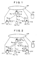
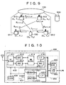
- FIG. 1 reference numerals are used as follows; 100 denotes a terminal, 110 to 112 denote base stations, 120 denotes a server, and 130 denotes a local area network (LAN).
- the terminal 100 has a function for sending a first wireless packet to each base station.
- Each of the base stations 110 to 112 has an internal clock and a function for measuring the receiving time of the first wireless packet received from the terminal 100.
- the reception timings measured by the clocks of the base stations 110 to 112 are defined as R pi_b0 , R p1_b1 , and R p1_b2 .
- the distance between the terminal and each base station is known from the time on which the base station receives a signal from the terminal 100.
- the coordinates (position) of the terminal is known from this known distance.
- each base station clock must be calibrated by detecting its clock time difference from the clocks of the other base stations.
- the base station 110 has a function for sending a second wireless packet to the base stations 111 and 112 respectively and a function for measuring the transmission timing of the packet.
- the transmission timing measured by the clock of the base station 110 is defined as T p2_b0 .
- the base station 110 transfers the reception timing R p1_b0 of the first wireless packet received from the terminal 100 and the transmission timing T p2_b0 of the second wireless packet from itself to the server 120.
- Each of the base stations 111 and 112 has a function for measuring the reception timing of the second wireless packet received from the base station 110.
- the reception timings measured by the clocks of the base stations 111 and 112 are defined as R p2_b1 and R p2_b2 .
- Each of the base stations 111 and 112 transfers the reception timing R p1_b1 /R p1_b2 of the first wireless packet received from the terminal 100 and the reception timing R p2_b1 /R p2/b2 of the second wireless packet received from the base station 110 to the server 120.
- the server 120 stores the coordinates (positions)(X 0 , Y 0 ), (X 1 , Y 1 ), and (X 2 , Y 2 ) of the base stations 110 to 112 beforehand and calculates the coordinates (X m , Y m ) of the terminal 100 according to the positions of the base stations 110 to 112 and the reception timings R p1_b0 , R p1_b1 , R p1_b2 , T p2_b0 , R p2_b1 , and R p2_b2 of the base stations.
- the distance between the base station 110 and each of the base stations 111 and 112 is already known, so the transfer time of the packet between the base stations is obtained by dividing the distance by light speed. Consequently, the reception timing at each of the base stations 111 and 112 (according to the clock of the base station 110) is obtained by adding the transfer time to the transmission timing from the base station 110.
- the clock time difference between base stations can thus be calibrated by detecting a difference between this reception timing and the reception timing measured by the clock of each of the base stations 111 and 112.
- An error of one ms will cause an error of 300m.
- E b ⁇ 0 _ bi R p ⁇ 2 _ bi - T p ⁇ 2 _ b ⁇ 0 - c - 1 ⁇ X 1 - X 0 2 + Y i - Y 0 2
- the clock error used in the past position measurement is used to calculate a clock error in the current position measurement. Consequently, the clock error comes to be detected more accurately.
- the clock error calculated by the expression 2 in the previous position measurement is defined as E b0_bi_N-1
- the clock error calculated by the expression in the position measurement performed before L times is defined as E b0_bi_N-L.
- E b ⁇ 0 _ bi t - R p ⁇ 2 _ bi _ N - 1 R p ⁇ 2 _ bi _ N - R p ⁇ 2 _ bi _ N - 1 ⁇ E b ⁇ 0 _ bi _ N + t - R p ⁇ 2 _ bi _ N R p ⁇ 2 _ bi _ N - 1 - R p ⁇ 2 _ bi _ N ⁇ E b ⁇ 0 _ bi _ N - 1
- E b ⁇ 0 _ bi _ N - k ⁇ m 0 m ⁇ k L t - E p ⁇ 2 _ bi _ N - m
- each base station is calibrated by detecting its time difference from each of other base stations in a period of time.
- the clock cycle differs among base stations due to the characteristics of the system itself and other conditions such as the ambient temperature, the clock difference among the base stations will change with time.
- each base station clock should be calibrated by detecting its clock difference at a suitable time.
- the terminal 100 has a function for sending a first wireless packet to respective base stations.
- Each of the base stations 210 to 212 has an internal clock and a function for measuring the reception timing of the first wireless packet received from the terminal 100.
- the reception timings of the wireless packet at the base stations 210 to 212 are defined as R p1_b0 , R p1_b1 , and R p1_b2 at this time.
- the base station 210 has a function for sending a second wireless packet to the base stations 211 and 212 respectively and a function for measuring the reception timing of the second wireless packet.
- the transmission timing of the second wireless packet measured by the clock of the base station 210 is defined as T p2_b0 .
- the base station 210 has a function for sending a third wireless packet to the base stations 211 and 212 respectively and a function for measuring the transmission timing of the packet.
- the transmission timing of the third wireless packet measured by the clock of the base station 210 is defined as T p3_b0 .
- the base station 210 transfers the reception timing R p1_b0 of the first wireless packet received from the terminal 100, the transmission timing T p2_b0 of the second wireless packet sent out from itself, and the transmission timing T p3_b0 of the third wireless packet sent out from itself to the server 220.
- the base station 210 may also send the second wireless packet earlier than the first wireless packet in this case.
- the base station 210 may also send the second and third wireless packets earlier than the third wireless packet.
- the base stations 211 and 212 have a function for measuring the reception timing of the second wireless packet received from the base station 210 respectively.
- the reception timings of the second wireless packet measured by the clocks of the base stations 211 and 212 are defined as R p2_b1 and R p2_b2 .
- Each of the base stations 211 and 212 has a function for measuring the reception timing of the third wireless packet received from the base station 210.
- the reception timings of the third wireless packet measured by the clocks of the base stations 211 and 212 are defined as R p3_b1 and R p3_b2 .
- the base stations 211 and 212 transfer the reception timings R p1_b1 and R p1_b2 of the first wireless packet received from the terminal 100, the reception timings R p2_b1 and R p2_b2 of the second wireless packet received from the base station 210, and the reception timings R p3_b1 and R p3_b2 of the third wireless packet received from the base station 210 to the server 220 respectively.
- the server 220 stores the positions (coordinates: (X 0 , Y 0 , (X 1 , Y 1 ), and (X 2 , Y 2 ) of the base stations 210 to 212 beforehand to calculate the position (X m , Y m ) of the terminal 100 according to the positions of those base stations and the reception timings R p1_b0 , R p1_b1 , R p1_b2 , T p2_b0 , R p2_b1 , R p2_b2 , T p3_b0 , R p3_b1 , and R p3_b2 obtained from the base stations 210 to 212.
- Each of the base stations 210 to 212 has its own clock.
- the clock accuracy is tolerated within ⁇ 25ppm, so that the error between base stations might increase by 50ms per second in maximum. A time error of 50ms will cause a distance error of 15000m.
- Multiplying the (R p2_bi -R p1_bi ) by (T p3_b0 -T p2_b0 )/(R p3_bi -R p2_bi ) can be compensated by the clock speed of the base station 210 to obtain a compensated value.
- the expression 3 is an expanded one from the expression 2. If the clock speed is the same between base stations (T p3_b0 -T p2_b0 )/(R p3_bi -R p2_bi ), the compensated value becomes 1, so that the expression 3 matches with the expression 2.
- E b ⁇ 0 _ bi E p ⁇ 1 _ bi + T p ⁇ 3 _ b ⁇ 0 - T p ⁇ 2 _ b ⁇ 0 R p ⁇ 3 _ bi - R p ⁇ 2 _ bi ⁇ R p ⁇ 2 _ bi - R p ⁇ 1 _ bi - T p ⁇ 2 _ b ⁇ 0 - c - 1 ⁇ X i - X 0 2 + Y i - Y 0 2
- the position (coordinates: X m , Y m ) of the terminal 100 is located by solving the expressions 1 and 3.
- the wireless LAN system in the third embodiment of the invention will be described with reference to FIG. 9 .
- at least one base station is provided with a function for measuring the transmission timing of each packet to detect a clock difference among base stations.
- no base station is provided with the function.
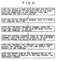
- the reference numerals are used as follows; 100 denotes a terminal, 910 to 913 denote base stations, 920 denotes a server, and 130 denotes a local area network (LAN).
- the terminal 100 has a function for sending a first wireless packet to respective base stations.
- Each of the base stations 911 to 913 has an internal clock and a function for measuring the reception timing of the first wireless packet received from the terminal 100.
- the reception timings of the wireless packet measured by the clocks of the base stations 911 to 913 are defined as R p1(i)_b1 , R p1(i)_b2 , and R p1(i)_b3 at this time.
- the base station 910 has a function for sending a second wireless packet to the base stations 911 and 913 respectively.
- the base station 910 may also have a function for sending the third wireless packet to those base stations.
- the base station 910 may also have a function for sending the second wireless packet earlier than the first wireless packet.
- the base station 910 may also send the second and third wireless packets earlier than the first wireless packet.
- Each of the base stations 911, 912, and 913 has a function for measuring the reception timing of the second wireless packet received from the base station 910.
- Each of the base stations 911 and 913 may also have a function for measuring the reception timing of the third wireless packet received from the base station 910.
- the server 920 stores the positions (coordinates: (X 0 , Y 0 , (X 1 , Y 1 ), (X 2 , Y 2 ) , and (X 3 , Y 3 ) of the base stations 910 to 913 beforehand to calculate the position (X m , Y m ) of the terminal 100 according to the positions of those base stations and the reception timings R p1(i)_b1 , R p1(i)_b2 , R p1(i)_b3 , R p2(j)_b1 , R p2(j)_b2 , R p2(j)_b3 obtained from the base stations 910 to 913.
- Each of the base stations 911 to 913 has its own clock.
- the clock error obtained by the expression 5 in the current position measurement and the clock errors obtained by the expression 5 in the position measurements performed L times in the past may be used to obtain the clock error E b1_bk to be used in the expression 4 just like in the first embodiment.
- the methods shown in the expressions 7 to 9 in the first embodiment may be used.
- the measurement results of the reception timings of the second, third, and g-th (g ⁇ 4) wireless packets may be used to find the error.
- the position (coordinates: X m , Y m ) of the terminal 100 is located by solving the expressions 4 and 5 or 4 and 6.
- three base stations are used to calculate the two-dimensional position of the terminal 100 to simplify the description.
- the number of base stations used for the calculation is not limited only to three; N base stations (N ⁇ 4) may be used.
- the equation in the expression 1 or 4 can be solved by, for example, the least square method.
- the "position calculating method and position calculating apparatus" disclosed in JP-A No.236163/2002 may also be used to calculate the position of the terminal 100 more accurately.
- the method for calculating the two-dimensional position of the terminal 100 is also included in the invention.
- the terminal requests detection of its position to the server through the connectable base station 310.
- the base station 310 is the nearest base station of the terminal.
- the server if the frequency channel used to detect the terminal position must be changed, instructs the terminal to change the channel. Thus, the terminal changes the frequency channel.
- the server instructs the base station 310 that has transferred the request from the terminal and the base stations 311 and 312 positioned near the base station 310 to monitor the frequency channel.
- the server which stores the positions of those base stations 310 to 312 beforehand, can identify the base stations (311 and 312) around one base station (310) easily.
- Each of the base stations instructed to monitor the frequency channel responds with a monitoring result.
- the server requests the terminal to send a first wireless packet to the frequency channel through the base station 310 that has transferred the request from the terminal.
- the terminal thus sends the first wireless packet to the frequency channel.
- Each of the base stations instructed to monitor the frequency channel measures its reception timing of the packet.
- the base station 310 after receiving the first wireless packet, sends a second wireless packet to the base stations 311 and 312 respectively through the frequency channel at a fixed interval.
- the base station measures the transmission timings.
- the base stations 311 and 312 measure the reception timing of the second wireless packet respectively.
- the base station 310 may send a third wireless packet to the base stations 311 and 312 respectively through the frequency channel at a fixed interval after sending the second wireless packet to them.
- the base station 310 measures its transmission timing while the base stations 311 and 312 measure their reception timing of the third wireless packet respectively.
- Each of the base stations 311 and 312 sends the measurement result of the wireless packet receiving or transmission timing to the server.
- the server calculates the position of the terminal using the method described above and reports the result to the terminal.
- each base station will be able to distinguish the first/second/third packet from others easily when in measuring of the reception timing.
- the terminal requests detection of its position to the server through the base station 310, which is the nearest to the terminal.
- the server instructs the base station 310 that has transferred the request from the terminal, as well as the base stations 311 and 312 around the base station 310 to monitor the frequency channel used for locating the terminal position.
- the server which stores the positions (coordinates) of those base stations beforehand, can find the base stations positioned around one base station easily.
- Each of the base stations 310 to 312 instructed to monitor the frequency channel returns the monitoring result to the server.
- the server requests the terminal to send a first wireless packet to the frequency channel through the base station 310.
- the base station 310 comes to send the packet to the frequency channel.
- This packet is assumed as the second wireless packet and the base station 310 measures its transmission timing.
- Each of the base stations 311 and 312 positioned around the base station 310 measures their reception timing of the second wireless packet.
- the terminal then sends the first wireless packet to the frequency channel.
- Each of the base stations 310 to 312 instructed to monitor the frequency channel thus measures its reception timing of the packet.
- the base station 310 may send a third wireless packet to the base stations 311 and 312 through the frequency channel at a fixed interval after receiving the first wireless packet.
- the base station 310 measures its transmission timing while the base stations 311 and 312 measure the third wireless packet reception timing respectively.
- Each of the base stations then sends the measured receiving or transmission timing to the server.
- the server calculates the position of the terminal using the method described above and reports the result to the terminal as the detected position.
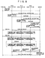
- the server instructs the base stations 911 to 913 to monitor the frequency channel used for locating the terminal position.
- Each of the base stations 911 to 913 instructed to monitor the frequency channel returns the monitoring result to the server.
- the server requests the terminal via the base station 910 to send a first wireless packet to the frequency channel.
- the base station 910 comes to send the packet to the frequency channel.
- This packet then becomes a second wireless packet.
- Each of the base stations 911 to 913 measures its reception timing of the second wireless packet.
- the terminal sends the first wireless packet to the frequency channel.
- Each of the base stations 911 to 913 instructed to monitor the frequency channel thus measures its reception timing of the first wireless packet. If the clock speed differs significantly among the base stations at this time, the server may further request the terminal to send the first wireless packet to the frequency channel again through the base station 910. In other words, the processings enclosed by a dotted line in FIG. 11 may be repeated. At this time, the base station 910 comes to send the wireless packet to the frequency channel again. This packet then becomes a third wireless packet. Each of the base stations 911 to 913 thus measures its reception timing of the third wireless packet. After the measurement, each base station sends the result to the server. The server then calculates the position of the terminal using the calculating method described above.
- the wireless LAN system usually uses a plurality of frequency channels. As described above, in order to realize multiple casting of a clock calibrating packet, a common frequency channel should be used among all the base stations related to the above-described terminal position locating.
- FIG. 5 shows a chart for describing the common frequency channel controlling method of the invention.
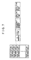
- FIG. 6 shows a flowchart of the frequency channel controlling method of the invention.
- reference numerals are used as follows; 5000 denotes a server, 5900 denotes a terminal, and 501* to 521* (*: any of 1 to 4) denote base stations.
- 5000 denotes a server
- 5900 denotes a terminal
- 501* to 521* (*: any of 1 to 4) denote base stations.
- four types of frequency channels are assigned to those base stations 501 to 521 and the last one digit of each base station number denotes the assigned frequency channel.
- No.1 frequency channel is assigned to the base station 5111 and No.4 frequency channel is assigned to the base station 5164.
- the terminal 5900 requests the server 5000 to detect its position through the base station 5111.
- the server 5000 selects four base stations 5063, 5102, 5122, and 5164 positioned around the base station 5111, so that a total of five base stations including the base station 5111 are used for the terminal position locating (step 601 in FIG. 6 ).
- the server 5000 decides the frequency channel used for the terminal position locating (step 602 in FIG. 6 ).
- the frequency channel deciding method may be, for example, a method for selecting the frequency channel (No.1 in FIG. 5 ) of the terminal that has requested the position locating as the frequency channel for locating the terminal position.
- the frequency channel (No.2 in FIG. 5 ) may be the most frequently assigned one among the selected base stations.
- the server 5000 instructs the base stations 5063, 5102, 5122, 5164, and 5111, as well as the terminal 5900 as needed, to use the decided frequency channel for the terminal position locating (step 603 in FIG. 6 ).
- the server 5000 may also instructs the base stations around the base stations 5063, 5102, 5122, 5164, and 5111 used for the position locating to stop the use of the frequency channel decided so as to suppress the interference from signals at the time of position locating; or that the server may also control so as to reduce the transmission power in the frequency channel (step 604 in FIG. 6 ). For example, if No.2 frequency channel is selected in FIG. 5 , the frequency channel is assigned to the base stations 5022 and 5202. Therefore, the server 5000 instructs those base stations 5022 and 5202 to stop the use of the frequency channel.
- the server 5000 locates the terminal position and reports the locating result to the terminal 5900 (step 605 in FIG. 6 ). After that, the server 5000 instructs the base stations 5063, 5102, 5122, 5164, and 5111 to restore their frequency channels. The server 5000 also cancels the instruction for controlling the transmission power in the frequency channel issued to the base stations 5022 and 5202 (step 606 in FIG. 6 ).
- the base station 400 is configured by a communication block 410, a storage block 420, a clock 430, a LAN I/F block 440, and a control block 450.
- the communication block 410 is configured by an RF block 411, a DAC (Digital to Analog Converter) 412, an ADC (Analog to Digital converter) 413, a BB block 414, a MAC block 415, and an I/F block 416.
- the RF block 411 converts the baseband signals inputted from the DAC 412 to high-frequency radio signals and outputs the converted signals to the antenna.
- the RF block 411 converts the high-frequency radio signals received from the antenna to baseband signals and outputs the converted signals to the ADC 413.
- the DAC 412 converts the digital baseband signals (I/Q) to analog baseband signals (I/Q) .
- the ADC 413 converts analog baseband signals (I/Q) to digital baseband signals (I/Q).
- the BB block 414 receives MPDU (MAC Protocol Data Units) from the MAC block 415 to generate baseband signals to be output to the DAC 412.
- the BB block 414 demodulates the baseband signals inputted from the ADC 413 to obtain the MPDU (MAC Protocol Data Units) to be output to the MAC block 415.
- the MAC block 415 controls the communications with other stations in accordance with the MAC (Media Access Control) protocol.
- the I/F block 416 sends/receives data to/from devices provided outside the communication block and enables the external devices to control the communication block 410.
- the storage block 420 is configured by a memory 421, a counter 422, and an I/F block 423.
- the memory 421 is instructed by the I/F block 423 to fetch the baseband signals (I/Q) received from the communication block 410 synchronously with the clock 430.
- the memory 421 is also instructed by the I/F block 423 to fetch the baseband signals (I/Q) received from the communication block 410 synchronously with the clock 430.
- the counter 422 counts the time (counter value) synchronously with the clock 430.
- the counter is instructed by the I/F block 423 to record the start or end of fetching each of the baseband signals written/read in/from the memory 421.
- the I/F block 423 enables devices provided outside the storage block 420 to read the memory/counter and to control the storage block 420.
- the clock 430 supplies a common clock to both of the communication block 410 and the storage block 420 so that both blocks synchronize with each other.
- the LAN I/F block 440 is an interface block used for a local area network.
- the control block 450 controls the communication block 410 and the LAN I/F block 440 and intermediates the communication between the terminal and the LAN.
- the control block 450 controls the LAN I/F 440 to communicate with the server.
- the control block 450 controls the communication block 410 and the storage block 420 to calculate the sending or reception timing of each wireless packet.
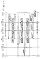
- the storage block 1020 is only a different item in the configuration shown in FIG. 10 ; all other items are equivalent to those in the configuration shown in FIG. 4 . Therefore, only the difference (storage block 1020) will be described here.
- the storage block 1020 is configured by a memory 1021, a counter 1022, and an I/F block 1023.
- the memory 1021 is instructed by the I/F block 1023 to fetch the baseband signals (I/Q) received from the communication block 410 synchronously with the clock 430.
- the counter 1022 counts the time (counter value) synchronously with the clock 430.
- the counter 1022 is instructed by the I/F block 1023 to record the start or end of fetching of each of the baseband signals written/read in/from the memory 1021.
- the I/F block 1023 enables devices provided outside the storage block 1020 to read the memory/counter and to control the storage block 1020.
- each wireless packet can be found by the peak position of a correlation value obtained from the cross correlation between each of the received baseband signals stored in the memory 421 or 1021 and a known signal sequence (ex., a preamble synchronization field pattern included in the received packet PLCP (Physical Layer Convergence Protocol) preamble), as well as a time (ex., fetching starting time) required for fetching a received baseband signal recorded in the counter 1022 422 or 1022.
- a processing delay between an input to the antenna end and an output from the ADC is included.
- the server may calculate the reception timing according to the received baseband signal fetched in the memory and the time required to fetch the signal transferred respectively thereto.
- the transmission timing of a wireless packet can be calculated, for example, according to a position at which the level of a transmit baseband signal stored in the memory 421 changes and a time (ex., a fetching starting time) required to fetch a transmit baseband signal recorded in the counter 422 easily.
- a time ex., a fetching starting time
- PLCP Physical Layer Convergence Protocol
- the transmission timing can be obtained more accurately if this delay time is estimated beforehand and this delay is compensated by the measured time.
- the server is not necessarily required to find the transmission timing of each wireless packet in each base station; the server may calculate the reception timing according to the transmit baseband signal fetched in the memory and the time required to fetch the signal, both of which are transferred to the server respectively.
- the "ranging and locating a position using a spectrum diffuse signal and an apparatus that employs the method" disclosed in JP-A No.14152/2002 can apply.
- a wireless LAN card can apply to a circuit 431 that includes the communication block 410 and a clock 430.
- a PC that includes the program included in the base station flowchart shown in FIG. 8 or 11 in itself can apply to the circuit 454 that includes the control block 450 and the LAN I/F 440.
- the server in this system can use a PC that includes a program used in the server flowchart shown in FIG. 3 or 8 or FIGS. 11 and 6 .
- the terminal in this system can use a notebook PC and/or PDA that includes a program shown in the terminal flowchart shown in FIG. 3 or 8 or 11 .
- FIG. 7 shows a data format of the information related each base station.
- the information is stored in the server.
- each of the base station information items 1,2, ..., n is an information unit related to one base station.
- the ID number described in each base station information identifies the base station that has the subject information.
- each base station information includes items of location, frequency channel number, sending delay time, and receiving delay time.
- the location denotes a position of a base station identified by an ID number with coordinates.
- the frequency channel number denotes a frequency channel number assigned to a base station identified by the ID number.
- Both sending and receiving delay times denote sending and receiving delay times of a base station identified by the ID number. These delay times are used to measure both sending and reception timings of a base station more accurately.
- a method for synchronizing base stations with each other in the above wireless LAN system is an application of the invention.
- wireless LAN signals have been used for ranging.
- the wireless LAN signals are used in wider ranges than the GPS signals.
- the bandwidth employed by the IEEE802.11b, which is one of the wireless LAN standards is 22MHz, which is wider than the GPS bandwidth 2MHz. Because of the wide bandwidth, the signal time resolution becomes high, thereby the terminal position can be located more accurately than the GPS signals.
- the terminal there is no need to provide the terminal with any device such as a GPS receiver to detect a position of the terminal, since the terminal uses only the already existing function for sending wireless packets.
- any device such as a GPS receiver to detect a position of the terminal
- the terminal uses only the already existing function for sending wireless packets.
- both cost and size of the terminal can be reduced.
- the method is required to include a function for measuring the reception timing of each wireless packet from the terminal and a function for synchronizing the base stations with each other.
- the invention realizes both of those functions with a common function for measuring the receiving or transmission timing of each wireless packet in each base station, so that both cost and size of the terminal are reduced due to the employed common function.
- the function for measuring the transmission timing of each wireless packet in each base station can be omitted, thereby the cost is more reduced. Because there is no need to synchronize base stations with each other actually and only a clock difference among the base stations is detected, there is no need to stop the operation of each base station for the synchronization.
- the second embodiment of the invention is effective to suppress the degradation of the locating accuracy to be caused by a clock error.
- both sending and receiving delay times in each base station are decided beforehand, both sending and reception timings of each wireless packet can be measured more accurately. If the transmission power in the frequency channel selected for position locating is controlled so as to be reduced in each of the base stations positioned around the base station selected for position locating, the interference by signals can be reduced, thereby the wireless packet reception timing measurement accuracy is more improved and the position locating accuracy is improved.
- a position of a terminal can be located very accurately without using any additional devices such as a GPS receiver in a wireless LAN system.
- FIG. 12 is a block of a server that may be used with terminal position locating methods of the present invention.
- the server includes components, each component being made up of software, hardware, or a combination thereof.
- a local area network interface (LAN I/F) 1202 is an interface that allows the server to communicate with LAN devices, including base stations, terminals, and other servers.
- a channel control instruction component 1204 may be configured to instruct base stations 911 to 913 to monitor the frequency channel used for locating the terminal position.
- a receiving response component 1206 may be configured to receive monitor results from the base stations instructed to monitor the frequency channel.
- a sending request component 1208 may be configured to send a request through the base station 910 to the terminal, requesting the terminal to send a first wireless packet.
- the sending request component may be further configured to send the request for the terminal to send the first wireless packet again as needed.
- a measurement result receiving component 1210 may be configured to receive a measurement result from each base station.
- a position calculation component 1212 may be configured to calculate the position of the terminal using the calculating method described above.
- the present invention includes a computer program product which is a storage medium (media) having instructions stored thereon/in which can be used to control, or cause, a computer to perform any of the processes of the present invention.
- the storage medium can include, but is not limited to, any type of disk including floppy disks, mini disks (MD's), optical disks, DVD, CD-ROMS, micro-drive, and magneto-optical disks, ROMs, RAMs, EPROMs, EEPROMs, DRAMs, VRAMs, flash memory devices (including flash cards), magnetic or optical cards, nanosystems (including molecular memory ICs), RAID devices, remote data storage/archive/warehousing, or any type of media or device suitable for storing instructions and/or data.
- the present invention includes software for controlling both the hardware of the general purpose/specialized computer or microprocessor, and for enabling the computer or microprocessor to interact with a human user or other mechanism utilizing the results of the present invention.
- software may include, but is not limited to, device drivers, operating systems, and user applications.
- computer readable media further includes software for performing the present invention, as described above.
- ⁇ Included in the programming (software) of the general/specialized computer or microprocessor are software modules for implementing the teachings of the present invention, including, but not limited to, calculating a position of a base station, detecting a clock time difference between the base station and another base station, measuring a reception timing of a signal received by the base station from the terminal, and locating the position of the terminal using at least the position of the base station, the clock time difference, and the reception timing, according to processes of the present invention.
- the present invention includes, but is not limited to, the following additional embodiments.
- a wireless communication system comprises a first base station having a first clock and known coordinates; and a second base station having a second clock and known coordinates, wherein the first and second base stations measure their reception timings of a first signal received from the terminal using their own clocks respectively, wherein the second base station measures its reception timing of a second signal received from the first base station using the second clock, wherein the system detects a clock time difference between the first and second clocks according to the coordinates of the first and second base stations, a transmission timing of the second signal measured by the first clock, and a reception timing of the second signal measured by the second clock, and wherein the system locates the position of the terminal according to the first signal reception timing measured by the first clock, the first signal reception timing measured by the second clock, and the detected time difference.
- the wireless communication system may further comprise a third base station having a third clock and known coordinates, wherein the third base station measures its reception timing of the first signal received from the terminal using the third clock, wherein the system detects a time difference between the first and third clocks according to the coordinates of the first and third base stations, a transmission timing of the second signal measured by the third clock, and a reception timing of the second signal measured by the third clock, wherein the system locates the position of the terminal according to the reception timing of the first signal measured by the first clock, the reception timing of the first signal measured by the second clock, the reception timing of the first signal measured by the third clock, and the detected time difference.
- the wireless communication system may be further configured to control at least the first to third base stations so that the same communication channel is used among the first to third base stations in prior to the locating of the terminal position.
- a base station is provided that is configured by a communication block, a storage block, a clock, a processing block, and a LAN I/F block, wherein a sending/reception timing of each wireless packet is detected according to a base band signal (I/Q) stored in the storage block and a time related to the storing operation.
- I/Q base band signal
- the base station may be further configured such that the reception timing of each wireless packet is detected according to a received base band signal (I/Q) stored in the storage block, a cross-correlation with a predetermined complex signal vector, and a storing operation-related time.
- a received base band signal I/Q
- a wireless communication system comprises a plurality of base stations, a plurality of communication channels, and a terminal, wherein the system sets a common communication channel for at least a first base station having a first clock and known coordinates, a second base station having a second clock and known coordinates, and a third base station having a third clock and known coordinates, the first to third base stations being included in the plurality of base stations, wherein each of the first to third base stations has a first measuring block for measuring a reception timing of a first signal received from the terminal using its own clock, wherein each of the second and third base stations has a second measuring block for measuring a reception timing of a second signal received from the first base station using its own clock, and wherein the system locates a position of the terminal according to the coordinates of the first to third base stations, the transmission timing of the second signal measured by the first clock, the reception timing of the second signal measured by the second clock, the reception timing of the second signal measured by the third clock, the reception timing of the first signal measured by the first clock
- the wireless communication system may be further configured to control the transmission power in each base station that uses the same communication channel, which are other than the base stations for which the common communication channel is set.
- a server for a system that comprises a plurality of base stations; a plurality of communication channels; and a terminal, wherein a first base station having a first clock and known coordinates, a second base station having a second clock and known coordinates, and a third base station having a third clock and known coordinates measure their reception timings of a first signal received from the terminal using their own clocks, the first to third base stations being included among the plurality of base stations, wherein the second and third base stations measure their reception timings of the second signal received from the first base station using their own clocks, wherein the server sets a common communication channel for the first to third base stations, and wherein the server locates a position of the terminal according to the coordinates of the first to third base stations, the transmission timing of the second signal measured by the first clock, the reception timing of the second signal measured by the second clock, the reception timing of the second signal measured by the third clock, the reception timing of the first signal measured by the first clock, the reception timing of the first signal measured by the second clock, and the reception
- a wireless communication system comprises a plurality of base stations; a plurality of communication channels; and a terminal, wherein the system sets a common communication channel for at least a first base station having known coordinates, a second base station having a second clock and known coordinates, a third base station having a third clock and known coordinates, and a fourth base station having a fourth clock and known coordinates, the first to fourth base stations being included in the plurality of base stations, wherein each of the second to fourth base stations has a first measuring block for measuring a reception timing of a first signal received from the terminal using its own clock, wherein each of the second to fourth base stations has a second measuring block for measuring a reception timing of a second signal received from the first base station using its own clock, and wherein the system locates the position of the terminal according to the coordinates of the first to fourth base stations, the reception timing of the second signal measured by the second clock, the reception timing of the second signal measured by the third clock, the reception timing of the second signal measured by the fourth clock, the reception timing
- a server for a system that comprises a plurality of base stations; a plurality of communication channels; and a terminal, wherein a first base station having known coordinates, a second base station having a second clock and known coordinates, a third base station having a third clock and known coordinates, and a fourth base station having a fourth clock and known coordinates measure their reception timings of a first signal received from the terminal using their own clocks, the first to fourth base stations being included in the plurality of base stations, wherein the second to fourth base stations measure their reception timings of a second signal received from the first base station using their own clocks, wherein the server sets a common communication channel for the first to fourth base stations and locates a position of the terminal according to the coordinates of the first to fourth base stations, the reception timing of the second signal measured by the second clock, the reception timing of the second signal measured by the third clock, the reception timing of the second signal measured by the fourth clock, the reception timing of the first signal measured by the second clock, the reception timing of the first signal measured by the second
Landscapes
- Engineering & Computer Science (AREA)
- Physics & Mathematics (AREA)
- General Physics & Mathematics (AREA)
- Radar, Positioning & Navigation (AREA)
- Remote Sensing (AREA)
- Computer Networks & Wireless Communication (AREA)
- Signal Processing (AREA)
- Mobile Radio Communication Systems (AREA)
- Position Fixing By Use Of Radio Waves (AREA)
Description
- The present invention generally relates to a position locating method employed for wireless communications and, more particularly, to a position locating method for wireless local area network (LAN) systems.
- The wireless LAN defined typically by the IEEE802.11 Standard is now employed widely in offices and public spaces such as hot spots due to its properties of compatibility with the Internet and fast data transfer with wide-ranged wireless media (semi-micro waves, semi-millimeter waves, infrared rays). In the wireless LAN, for example,
JP-A No.264090/2001 - On the other hand,
JP-A No.156882/2000 -
WO 02/41504 A2 -
WO 01/15340 A1 - Under the circumstances, the present invention according to
independent claims 1 and 9 aims to provide a method for locating positions of a terminal of a wireless LAN system accurately without providing the terminal with a GPS receiver. - In order to achieve the object, one aspect of the invention resides in a wireless communication system where some base station detect clock time differences between some of them through mutual wireless communication and measure receiving times for each of them with respect to a signal received from the terminal, and then locate the terminal position according to the detected clock time differences, the measured receiving times, and the position of each base station.
- Concretely, a wireless communication system of the related art may comprise: a first base station having a first clock and known coordinates; a second base station having a second clock and known coordinates; and a terminal. Each of the first and second base stations measures its receiving time of a first signal received from the terminal using its own clock while the second base station also measures its receiving time of a second signal received from the first base station using the second clock. The system then detects a time difference between the first and second clocks according to the coordinates of the first and second base stations, the transmission timing of the second signal measured by the first clock, and the receiving time of the second signal measured by the second clock, and then locates the position of the terminal according to the receiving time of the first signal measured by the first signal, the receiving time of the first signal measured by the second clock, and the detected time difference.
- In another aspect, the wireless communication system may further comprise a third base station having a third clock and known coordinates, wherein: the third base station measures a receiving time of a first signal received from the terminal using the third clock; and the system detects a time difference between the first and third clocks according to the coordinates of the first and third base stations, the transmission timing of the second signal measured by the first clock, and the receiving time of the second signal measured by the third clock, and then locates the position of the terminal according to the receiving time of the first signal measured by the first clock, the receiving time of the first signal measured by the second clock, the receiving time of the first signal measured by the third clock, and the detected time difference.
- Preferably, the system may be controlled such that the same communication channel is used among those first to third base stations before the position locating.
- In another aspect, the wireless communication system may comprise a plurality of base stations, a plurality of communication channels, and a terminal, wherein: the system sets a common communication channel at least for a first base station having a first clock and known coordinates, a second base station having a second clock and known coordinates, and a third base station having a third clock and known coordinates, the first to third base stations are included in the plurality of base stations mentioned above; each of the first to third base stations has a first measuring block for measuring a receiving time of a first signal received from the terminal using its own clock while each of the second and third base stations has a second measuring block for measuring a receiving time of a second signal received from the first base station using its own clock; and then the system locates the position of the terminal according to the coordinates of the first to third base stations, the transmission timing of the second signal measured by the first clock, the receiving time of the second signal measured by the second clock, the receiving time of the second signal measured by the third clock, the receiving time of the first signal measured by the first clock, the receiving time of the first signal measured by the second clock, and the receiving time of the first signal measured by the third clock.
- At this time, the transmission power may be controlled in the base stations other than those for which a common communication channel is set if they use the same communication channel.
- In another aspect, a server may be provided for the wireless communication system comprising a plurality of base stations, a plurality of communication channels, and a terminal, wherein among the plurality of base stations in the system, each of the first base station having a first clock and known coordinates, the second base station having a second clock and known coordinates, and the third base station having a third clock and known coordinates measures its receiving time of a first signal received from the terminal using its own clock while each of the second and third base stations measures its receiving time of a second signal received from the first base station using its own clock; and wherein the server sets a common communication channel for the first to third base stations, and then locates the position of the terminal according to the coordinates of the first to third base stations, the transmission timing of the second signal measured by the first clock, the receiving time of the second signal measured by the second clock, the receiving time of the second signal measured by the third clock, the receiving time of the first signal measured by the first clock, the receiving time of the first signal measured by the second clock, the receiving time of the first signal measured by the third clock.
- While a description has been made for measurement of a signal transmission timing, the invention may be modified such that measurement of the signal transmission timing said above is not performed. That is, the invention resides in the wireless communication system which comprises a first base station having known coordinates, a second base station having a second clock and known coordinates, a third base station having a third clock and known coordinates, and a terminal, wherein: each of the second and third base stations measures its receiving time of a first signal received from the terminal using its own clock while each of the second and third base stations measures its receiving time of the second signal received from the first base station using its own clock; and the system detects a time difference between the second and third clocks according to the coordinates of the first to third base stations, the receiving time of the second signal measured by the second clock, the receiving time of the second signal measured by the third clock; and then the system locates the position of the terminal according to the receiving time of the first signal measured by the second clock, the receiving time of the first signal measured by the third clock, and the detected time difference.
- Further, the invention may be modified such that: the wireless communication system includes a fourth base station having a fourth clock and known coordinates; allows the fourth base station to measure its receiving time of the first signal received from the terminal using the fourth clock; detects a time difference between the second and fourth blocks according to the coordinates of the first, second, and fourth base stations, the receiving time of the second signal measured by the second clock, the receiving time of the second signal measured by the fourth clock; and then locates the position of the terminal according to the receiving time of the first signal measured by the second clock, the receiving time of the first signal measured by the third clock, the receiving time of the first signal measured by the fourth clock, and the detected time difference.
- Further, the invention may be modified such that the system controls the first to fourth base stations in prior to the position locating such that the same communication channel is used for all of those first to fourth base stations.
- In another aspect, the invention resides in a server that locates a position of a terminal according to a receiving time of a signal received at each base station from another base station through mutual communication, a receiving time of a signal from the terminal at each base station, and a position of each base station.
- In another aspect, the invention resides in a server that locates a position of a terminal according to a signal received at each base station from another base station through mutual communication and a receiving time of the signal, a signal received at each base station from the terminal and the receiving time of the signal, and a position of each base station.
- Further, the invention may be modified such that the server stores a delay time in the receiving processing at each base station and use the delay time to locate the position of the terminal.
- Further, the invention may be modified such that the server decides both base station and frequency channel used to locate the position of the terminal according to the position of the base station that transfers the position locating request issued from the terminal. At this time, the server may control the transmission power in the frequency channel of each base station that is not used for the position locating, according to both of the base station and its frequency channel used for locating the position of the terminal.
- In another aspect, the invention resides in the base station which comprises a communication block, a storage block, a clock, a processing block, and a local area network interface (LAN I/F) block, wherein the base station identifies the receiving time of each wireless packet according to the baseband signal (I/Q) stored in the storage block and the storing operation time.
- Further, the invention may be modified such that the receiving time of the wireless packet is identified according to the cross-correlation between a received baseband signal (I/Q) stored in the storage block and a predetermined complex signal vector, as well as the storing operation time.
- In another aspect, the invention resides in an inter-base-station synchronizing method that allows the base stations in a wireless LAN system to synchronize with each other by detecting a clock time difference among those base stations through mutual wireless communication. At this time, each base station in the wireless LAN system may repeat the mutual wireless communication by a plurality of times to detect its clock time difference rate per unit time from others so that the base stations synchronize with each other.
- In another aspect, the invention resides in a wireless communication system which comprises a plurality of base stations, a plurality of communication channels, and a terminal; wherein the system sets a common communication channel for at least a first base station having known coordinates, a second base station having a second clock and known coordinates, a third base station having a third clock and known coordinates, and a fourth base station having a fourth clock and known coordinates, the first to fourth base stations being included in the plurality of base stations; wherein each of the second to fourth base stations has a first measuring block for measuring a receiving time of a first signal received from the terminal using its own clock; wherein each of the second to fourth base stations has a second measuring block for measuring a receiving time of a second signal received from the first base station using its own clock; and wherein the system locates the position of the terminal according to the coordinates of the first to fourth base stations, the receiving time of the second signal measured by the second clock, the receiving time of the second signal measured by the third clock, the receiving time of the second signal measured by the fourth clock, the receiving time of the first signal measured by the second clock, the receiving time of the first signal measured by the third clock, and the receiving time of the first signal measured by the fourth clock. At this time, the transmission power in the base stations other than those for which the common communication channel is set may be controlled if they use the same communication channel.
- In another aspect, the invention resides in a server for a wireless communication system comprising a plurality of base stations, a plurality of communication channels, and a terminal; wherein among the plurality of base stations in the system, the first base station having known coordinates, the second base station having a second clock and known coordinates, the third base station having a third clock and known coordinates, and the fourth base station having a fourth clock and known coordinates measure their receiving times of a first signal received from the terminal using their own clocks while the second to fourth base stations measure their receiving times of a second signal received from the first base station using their own clocks; wherein the server sets a common communication channel for the first to fourth base stations and locates the position of the terminal according to the coordinates of the first to fourth base stations, the receiving time of the second signal measured by the second clock, the receiving time of the second signal measured by the third clock, the receiving time of the second signal measured by the fourth clock, the receiving time of the first signal measured by the second clock, the receiving time of the first signal measured by the third clock, and the receiving time of the first signal measured by the fourth clock.
- The invention encompasses other embodiments of a system, a method, an apparatus, and a computer-readable medium, which are configured as set forth above and with other features and alternatives.
- The present invention will be readily understood by the following detailed description in conjunction with the accompanying drawings. To facilitate this description, like reference numerals designate like structural elements.
-
FIG. 1 is a block diagram of a wireless LAN system in the first embodiment of the invention; -
FIG. 2 is a block diagram of a wireless LAN system in the second embodiment of the invention; -
FIG. 3 is a system flowchart of position locating according to the invention; -
FIG. 4 is a block diagram of a base station of the invention; -
FIG. 5 is a flat view for describing a method for controlling a frequency channel according to the invention; -
FIG. 6 is a flowchart of the processings by the frequency channel controlling method of the invention; -
FIG. 7 is a data format of base station information to be stored in a server according to the invention; -
FIG. 8 is a system flowchart for position locating according to the invention; -
FIG. 9 is a block diagram of a wireless LAN system in the third embodiment of the invention; -
FIG. 10 is another block diagram of the base station of the invention; and -
FIG. 11 is another system flowchart for position locating according to the invention. -
FIG. 12 is a block of a server that may be used with position locating methods of the present invention. - An invention for a method, system, and apparatus for detecting a position of a terminal in a network accurately without a GPS receiver is disclosed. Numerous specific details are set forth in order to provide a thorough understanding of the present invention. It will be understood, however, to one skilled in the art, that the present invention may be practiced without some or without all of these specific details.
- Hereunder, a preferred embodiment of a wireless LAN system of the related art will be described with reference to
FIG. 1 . InFIG. 1 , reference numerals are used as follows; 100 denotes a terminal, 110 to 112 denote base stations, 120 denotes a server, and 130 denotes a local area network (LAN). The terminal 100 has a function for sending a first wireless packet to each base station. Each of thebase stations 110 to 112 has an internal clock and a function for measuring the receiving time of the first wireless packet received from the terminal 100. The reception timings measured by the clocks of thebase stations 110 to 112 are defined as Rpi_b0, Rp1_b1, and Rp1_b2. The distance between the terminal and each base station is known from the time on which the base station receives a signal from the terminal 100. The coordinates (position) of the terminal is known from this known distance. However, because the reception timings Rp1_b0, Rp1_b1, and Rp1_b2 are measured in accordance with the clock specific to each of the base stations and the synchronization among the clocks of those base stations is not assured, each base station clock must be calibrated by detecting its clock time difference from the clocks of the other base stations. - The
base station 110 has a function for sending a second wireless packet to thebase stations base station 110 is defined as Tp2_b0. Thebase station 110 transfers the reception timing Rp1_b0 of the first wireless packet received from the terminal 100 and the transmission timing Tp2_b0 of the second wireless packet from itself to theserver 120. Each of thebase stations base station 110. The reception timings measured by the clocks of thebase stations base stations base station 110 to theserver 120. Theserver 120 stores the coordinates (positions)(X0, Y0), (X1, Y1), and (X2, Y2) of thebase stations 110 to 112 beforehand and calculates the coordinates (Xm, Ym) of the terminal 100 according to the positions of thebase stations 110 to 112 and the reception timings Rp1_b0, Rp1_b1, Rp1_b2, Tp2_b0, Rp2_b1, and Rp2_b2 of the base stations. - The distance between the
base station 110 and each of thebase stations base stations 111 and 112 (according to the clock of the base station 110) is obtained by adding the transfer time to the transmission timing from thebase station 110. The clock time difference between base stations can thus be calibrated by detecting a difference between this reception timing and the reception timing measured by the clock of each of thebase stations - Next, a description will be made for a method for calculating the coordinates (position) of the terminal 100 in the server. Each of the
base stations 110 to 112 has a clock. The coordinates (Xm, Ym (position)) of the terminal are obtained by solving the equation (i = 1,2) shown in theexpression 1. In the equation, "c" denotes the light speed, " Eb0_b1 (i= 1, 2)" denotes a clock error of each of thebase stations base station 110.
- Here, the position of the terminal will not be calculated if the clock of each of the
base stations base station 110. An error of one ms will cause an error of 300m. However, those errors can be found by the expression 2 (i= 1, 2) according to the measurement result of the second wireless packet sending/reception timing. In the expression 2 (i= 1, 2), the right side (Rp2_bi = Tp2_b0) denotes an error of the second wireless packet reception timing in the base station 11(i= 1, 2) with respect to the second wireless packet transmission timing in thebase station 110. The third part of the right side denotes a transfer time between thebase stations 110 and 11i (i= 1, 2).
- By solving the
expressions - When positions of the terminal 100 are measured continuously, for example, in a navigation service, the clock error used in the past position measurement is used to calculate a clock error in the current position measurement. Consequently, the clock error comes to be detected more accurately. Hereinafter, the clock error calculated by
Expression 2 in the current position measurement is defined as Eb0_bi_N (i=1,2), the clock error calculated by theexpression 2 in the previous position measurement is defined as Eb0_bi_N-1, and the clock error calculated by the expression in the position measurement performed before L times is defined as Eb0_bi_N-L. In the current position measurement, the time on which the base station 11i(i=1,2) receives the second wireless packet is defined as Rp2_bi_N and the time on which the base station 11i(i=1,2) receives the second wireless packet in the previous position measurement is defined as Rp2_Bi_N-1, and the time on which the base station 11i(i=1,2) receives the second wireless packet in the position measurement before L times is defined as Rp2_bi_L-N. - For example, a clock error of L=1, that is, the clock errors in the current and last position measurements are used, the clock error Eb0_bi(i=1,2) needed in the
expression 1 can be obtained by substituting t=Rp1_bt for the expression 7.
- Generally, if the clock errors in the current position measurement and the position measurements performed by L times in the past are used, the clock error Eb0_bi(i=1,2) needed in the
expression 1 can be obtained by substituting t=Rp1_bi for the L-order polynomial expression shown, for example, in the expression 8.
- In addition, if the clock errors in the current position measurement and the position measurements performed L times in the past are used, the clock error Eb0_bi(i=1,2) needed in the
expression 1 can be obtained by substituting t=Rp1_bi for the approximation of a regression line shown in the expression 9.


- Next, the wireless LAN system in the second embodiment of the related art will be described with reference to
FIG. 2 . As described above, in the first embodiment shown inFIG. 1 , the clock in each base station is calibrated by detecting its time difference from each of other base stations in a period of time. However, if the clock cycle differs among base stations due to the characteristics of the system itself and other conditions such as the ambient temperature, the clock difference among the base stations will change with time. In such a case, each base station clock should be calibrated by detecting its clock difference at a suitable time. - In
FIG. 2 , reference numerals are used as follows; 100 denotes a terminal, 210 to 212 denote base stations, 220 denotes a server, and 130 denotes a local area network (LAN). The terminal 100 has a function for sending a first wireless packet to respective base stations. Each of thebase stations 210 to 212 has an internal clock and a function for measuring the reception timing of the first wireless packet received from the terminal 100. The reception timings of the wireless packet at thebase stations 210 to 212 are defined as Rp1_b0, Rp1_b1, and Rp1_b2 at this time. - The
base station 210 has a function for sending a second wireless packet to thebase stations base station 210 is defined as Tp2_b0. Thebase station 210 has a function for sending a third wireless packet to thebase stations base station 210 is defined as Tp3_b0. Thebase station 210 transfers the reception timing Rp1_b0 of the first wireless packet received from the terminal 100, the transmission timing Tp2_b0 of the second wireless packet sent out from itself, and the transmission timing Tp3_b0 of the third wireless packet sent out from itself to theserver 220. Thebase station 210 may also send the second wireless packet earlier than the first wireless packet in this case. Thebase station 210 may also send the second and third wireless packets earlier than the third wireless packet. - The
base stations base station 210 respectively. The reception timings of the second wireless packet measured by the clocks of thebase stations base stations base station 210. The reception timings of the third wireless packet measured by the clocks of thebase stations base stations base station 210, and the reception timings Rp3_b1 and Rp3_b2 of the third wireless packet received from thebase station 210 to theserver 220 respectively. - The
server 220 stores the positions (coordinates: (X0, Y0, (X1, Y1), and (X2, Y2) of thebase stations 210 to 212 beforehand to calculate the position (Xm, Ym) of the terminal 100 according to the positions of those base stations and the reception timings Rp1_b0, Rp1_b1, Rp1_b2, Tp2_b0, Rp2_b1, Rp2_b2, Tp3_b0, Rp3_b1, and Rp3_b2 obtained from thebase stations 210 to 212. - Next, a method for calculating a position of the terminal 100 employed for the
server 220 will be described. - Each of the
base stations 210 to 212 has its own clock. The position (coordinates: Xm, Ym) of the terminal 100 is obtained by solving the equation (i= 1, 2) shown as theexpression 1. Here, Eb0_bi (i= 1, 2) denotes an error of the clock of each of thebase station base station 210. If the clock speed varies among thebase stations 210 to 212, the error Eb0_bi (i= 1, 2) of each of thebase stations base station 210 will change with time. Actually, in the case of the wireless LAN standard IEEE802.11, the clock accuracy is tolerated within ±25ppm, so that the error between base stations might increase by 50ms per second in maximum. A time error of 50ms will cause a distance error of 15000m. However, the error can be found by the expression 3 (i= 1,2) according to the measurement results of the sending and reception timings of the second and third wireless packets. In the expression 3 (i= 1,2), the (Tp3_b0-Tp2_b0)/(Rp3_bi-Rp2_bi) enclosed by the parentheses of the right side denotes a ratio of the clock speed of thebase station 210 to the clock speed of the base station 21i (i= 1,2). The (Rp2_bi-Rp1_bi) of the right side denotes an error of the reception timing of the second wireless packet with respect to the reception timing of the first wireless packet in the base station 21i (i= 1,2). Multiplying the (Rp2_bi-Rp1_bi) by (Tp3_b0-Tp2_b0)/(Rp3_bi-Rp2_bi), the error of the second wireless packet reception timing with respect to the first wireless packet reception timing in the base station 21i (i= 1,2) can be compensated by the clock speed of thebase station 210 to obtain a compensated value. Consequently, the value enclosed by the parentheses of the right side takes a value obtained by compensating the second wireless packet reception timing in the base station 21i (i= 1,2) by the clock speed of thebase station 210. Theexpression 3 is an expanded one from theexpression 2. If the clock speed is the same between base stations (Tp3_b0-Tp2_b0)/(Rp3_bi-Rp2_bi), the compensated value becomes 1, so that theexpression 3 matches with theexpression 2.
- Consequently, the position (coordinates: Xm, Ym) of the terminal 100 is located by solving the
expressions - Next, the wireless LAN system in the third embodiment of the invention will be described with reference to
FIG. 9 . In the embodiments shown inFIGS. 1 and 2 , at least one base station is provided with a function for measuring the transmission timing of each packet to detect a clock difference among base stations. In this third embodiment, however, no base station is provided with the function. - In
FIG. 9 , the reference numerals are used as follows; 100 denotes a terminal, 910 to 913 denote base stations, 920 denotes a server, and 130 denotes a local area network (LAN). The terminal 100 has a function for sending a first wireless packet to respective base stations. Each of thebase stations 911 to 913 has an internal clock and a function for measuring the reception timing of the first wireless packet received from the terminal 100. The reception timings of the wireless packet measured by the clocks of thebase stations 911 to 913 are defined as Rp1(i)_b1, Rp1(i)_b2, and Rp1(i)_b3 at this time. - The
base station 910 has a function for sending a second wireless packet to thebase stations base station 910 may also have a function for sending the third wireless packet to those base stations. Thebase station 910 may also have a function for sending the second wireless packet earlier than the first wireless packet. Thebase station 910 may also send the second and third wireless packets earlier than the first wireless packet. - Each of the
base stations base station 910. The reception timings of the second wireless packet measured by the clocks of thebase stations base stations base station 910. The reception timings of the third wireless packet measured by the clocks of thebase stations base stations base station 910 respectively, and further the reception timings Rp2(j)_b1, Rp2(j)_b2, and Rp2(j)_b3 (j=3) of the third wireless packet received from thebase station 210 as needed to theserver 920 respectively. - The
server 920 stores the positions (coordinates: (X0, Y0, (X1, Y1), (X2, Y2) , and (X3, Y3) of thebase stations 910 to 913 beforehand to calculate the position (Xm, Ym) of the terminal 100 according to the positions of those base stations and the reception timings Rp1(i)_b1, Rp1(i)_b2, Rp1(i)_b3, Rp2(j)_b1, Rp2(j)_b2, Rp2(j)_b3 obtained from thebase stations 910 to 913. - Next, a method for calculating the position of the terminal 100 employed for the
server 920 will be described. Each of thebase stations 911 to 913 has its own clock. The position (coordinates: Xm, Ym) of the terminal 100 is obtained by solving the equation (k= 2,3) shown in the expression 4. Here, Eb1_bk (k= 2,3) denotes an error of the clock of each of thebase station base station 911. However, the error can be found by the expression 5 (k= 2,3, j=2) according to the measurement results of the reception timings of the second wireless packet.

- Also in this embodiment, the clock error obtained by the expression 5 in the current position measurement and the clock errors obtained by the expression 5 in the position measurements performed L times in the past may be used to obtain the clock error Eb1_bk to be used in the expression 4 just like in the first embodiment. Concretely, the methods shown in the expressions 7 to 9 in the first embodiment may be used.
- In the case where the clock speed varies among the
base stations 911 to 913 and the error Eb1_bk (k=2,3) of the clock of each of thebase stations base station 911, the measurement result of the reception timing of the third wireless packet may be used to find the error using the expression 6 (k= 2,3, j=2, h=3).
- In the expression 6 (k=2,3, j=2, h=3), the (Rp2(h)_b1-Rp2(j)_b1)/(Rp2(h)_bk-Rp2(j)_bk) enclosed by the parentheses of the right side denotes a ratio of the clock speed of the
base station 911 to the clock speed of the base station 91k (k=2,3). The expression 6 is an expanded one from the expression 5. When the clock error Eb1_bk (k=2,3) does not change with time, that is, when the clock speed ratio is 1, the expression 6 matches with the expression 5. At this time, the measurement results of the reception timings of the second and third wireless packets are insufficient to find the clock error Eb1_bk (k=2,3). In such a case, the measurement results of the reception timings of the second, third, and g-th (g≥4) wireless packets may be used to find the error. In this connection, the Ebi_bk (k=2,3) may be decided according to a plurality of clock errors obtained by the expression 6 (k= 2,3, j=e, h=f, e≠f, e≥2, f≥3), for example, by averaging the plurality of clock errors obtained by the expression 6. - Consequently, the position (coordinates: Xm, Ym) of the terminal 100 is located by solving the expressions 4 and 5 or 4 and 6.
- In this third embodiment, three base stations are used to calculate the two-dimensional position of the terminal 100 to simplify the description. However, the number of base stations used for the calculation is not limited only to three; N base stations (N≥4) may be used. In this connection,
expressions 1 to 3 may be used as (i=1,2,... N-1). Expressions 4 to 6 may be used as (k=1,2,... N). The equation in theexpression 1 or 4 can be solved by, for example, the least square method. The "position calculating method and position calculating apparatus" disclosed inJP-A No.236163/2002 expressions 1 to 3 with respect to the N base stations (N≥4) to form the expressions as (i=1,2, ..., N-1) or the z coordinate is added to the expressions 4 to 6 to form the expressions as (k=1,2,...,N) . - Next, a description will be made for a system flowchart for detecting a position of the terminal with reference to
FIG. 3 . At first, the terminal requests detection of its position to the server through theconnectable base station 310. Usually, thebase station 310 is the nearest base station of the terminal. The server, if the frequency channel used to detect the terminal position must be changed, instructs the terminal to change the channel. Thus, the terminal changes the frequency channel. After that, the server instructs thebase station 310 that has transferred the request from the terminal and thebase stations base station 310 to monitor the frequency channel. The server, which stores the positions of thosebase stations 310 to 312 beforehand, can identify the base stations (311 and 312) around one base station (310) easily. Each of the base stations instructed to monitor the frequency channel responds with a monitoring result. The server then requests the terminal to send a first wireless packet to the frequency channel through thebase station 310 that has transferred the request from the terminal. The terminal thus sends the first wireless packet to the frequency channel. Each of the base stations instructed to monitor the frequency channel measures its reception timing of the packet. Thebase station 310, after receiving the first wireless packet, sends a second wireless packet to thebase stations base stations base station 310 may send a third wireless packet to thebase stations base station 310 measures its transmission timing while thebase stations base stations - If a unique code is set in each of the first to third wireless packets, each base station will be able to distinguish the first/second/third packet from others easily when in measuring of the reception timing.
- Next, a description will be made for another system flowchart for detecting a position of the terminal with reference to
FIG. 8 . At first, the terminal requests detection of its position to the server through thebase station 310, which is the nearest to the terminal. The server then instructs thebase station 310 that has transferred the request from the terminal, as well as thebase stations base station 310 to monitor the frequency channel used for locating the terminal position. The server, which stores the positions (coordinates) of those base stations beforehand, can find the base stations positioned around one base station easily. Each of thebase stations 310 to 312 instructed to monitor the frequency channel returns the monitoring result to the server. After that, the server requests the terminal to send a first wireless packet to the frequency channel through thebase station 310. At this time, thebase station 310 comes to send the packet to the frequency channel. This packet is assumed as the second wireless packet and thebase station 310 measures its transmission timing. Each of thebase stations base station 310 measures their reception timing of the second wireless packet. The terminal then sends the first wireless packet to the frequency channel. Each of thebase stations 310 to 312 instructed to monitor the frequency channel thus measures its reception timing of the packet. If the clock speed differs significantly among the base stations at this time, thebase station 310 may send a third wireless packet to thebase stations base station 310 measures its transmission timing while thebase stations - Next, a description will be made for a system flowchart for locating a position of the terminal by a server in the wireless LAN system shown in
FIG. 9 with reference toFIG. 11 . At first, the server instructs thebase stations 911 to 913 to monitor the frequency channel used for locating the terminal position. Each of thebase stations 911 to 913 instructed to monitor the frequency channel returns the monitoring result to the server. The server then requests the terminal via thebase station 910 to send a first wireless packet to the frequency channel. At this time, thebase station 910 comes to send the packet to the frequency channel. This packet then becomes a second wireless packet. Each of thebase stations 911 to 913 measures its reception timing of the second wireless packet. After that, the terminal sends the first wireless packet to the frequency channel. Each of thebase stations 911 to 913 instructed to monitor the frequency channel thus measures its reception timing of the first wireless packet. If the clock speed differs significantly among the base stations at this time, the server may further request the terminal to send the first wireless packet to the frequency channel again through thebase station 910. In other words, the processings enclosed by a dotted line inFIG. 11 may be repeated. At this time, thebase station 910 comes to send the wireless packet to the frequency channel again. This packet then becomes a third wireless packet. Each of thebase stations 911 to 913 thus measures its reception timing of the third wireless packet. After the measurement, each base station sends the result to the server. The server then calculates the position of the terminal using the calculating method described above. - In this case, it is also possible to add processings performed by the terminal to request the server to detect its position through the
base station 910 first and the server to report the detection result to the terminal finally as shown in the flowcharts inFIGS. 3 and8 . - Next, a description will be made for a method for controlling a frequency channel in the wireless LAN system of the invention with reference to
FIGS. 5 and6 . The wireless LAN system usually uses a plurality of frequency channels. As described above, in order to realize multiple casting of a clock calibrating packet, a common frequency channel should be used among all the base stations related to the above-described terminal position locating. -
FIG. 5 shows a chart for describing the common frequency channel controlling method of the invention.FIG. 6 shows a flowchart of the frequency channel controlling method of the invention. InFIG. 5 , reference numerals are used as follows; 5000 denotes a server, 5900 denotes a terminal, and 501* to 521* (*: any of 1 to 4) denote base stations. In the example shown inFIG. 5 , four types of frequency channels are assigned to those base stations 501 to 521 and the last one digit of each base station number denotes the assigned frequency channel. For example, No.1 frequency channel is assigned to thebase station 5111 and No.4 frequency channel is assigned to thebase station 5164. - Assume that the terminal 5900 requests the
server 5000 to detect its position through thebase station 5111. Theserver 5000 then selects fourbase stations base station 5111, so that a total of five base stations including thebase station 5111 are used for the terminal position locating (step 601 inFIG. 6 ). - After that, the
server 5000 decides the frequency channel used for the terminal position locating (step 602 inFIG. 6 ). The frequency channel deciding method may be, for example, a method for selecting the frequency channel (No.1 inFIG. 5 ) of the terminal that has requested the position locating as the frequency channel for locating the terminal position. The frequency channel (No.2 inFIG. 5 ) may be the most frequently assigned one among the selected base stations. - The
server 5000 instructs thebase stations FIG. 6 ). Note that theserver 5000 may also instructs the base stations around thebase stations FIG. 6 ). For example, if No.2 frequency channel is selected inFIG. 5 , the frequency channel is assigned to thebase stations server 5000 instructs thosebase stations - The
server 5000 then locates the terminal position and reports the locating result to the terminal 5900 (step 605 inFIG. 6 ). After that, theserver 5000 instructs thebase stations server 5000 also cancels the instruction for controlling the transmission power in the frequency channel issued to thebase stations 5022 and 5202 (step 606 inFIG. 6 ). - Next, a description will be made for a configuration of the base station employed for the LAN system of the invention with reference to
FIG. 4 . InFIG. 4 , thebase station 400 is configured by acommunication block 410, astorage block 420, aclock 430, a LAN I/F block 440, and acontrol block 450. - The
communication block 410 is configured by anRF block 411, a DAC (Digital to Analog Converter) 412, an ADC (Analog to Digital converter) 413, aBB block 414, aMAC block 415, and an I/F block 416. TheRF block 411 converts the baseband signals inputted from theDAC 412 to high-frequency radio signals and outputs the converted signals to the antenna. TheRF block 411 converts the high-frequency radio signals received from the antenna to baseband signals and outputs the converted signals to theADC 413. TheDAC 412 converts the digital baseband signals (I/Q) to analog baseband signals (I/Q) . - The
ADC 413 converts analog baseband signals (I/Q) to digital baseband signals (I/Q). TheBB block 414 receives MPDU (MAC Protocol Data Units) from the MAC block 415 to generate baseband signals to be output to theDAC 412. TheBB block 414 demodulates the baseband signals inputted from theADC 413 to obtain the MPDU (MAC Protocol Data Units) to be output to theMAC block 415. TheMAC block 415 controls the communications with other stations in accordance with the MAC (Media Access Control) protocol. The I/F block 416 sends/receives data to/from devices provided outside the communication block and enables the external devices to control thecommunication block 410. - The
storage block 420 is configured by amemory 421, acounter 422, and an I/F block 423. Thememory 421 is instructed by the I/F block 423 to fetch the baseband signals (I/Q) received from thecommunication block 410 synchronously with theclock 430. Thememory 421 is also instructed by the I/F block 423 to fetch the baseband signals (I/Q) received from thecommunication block 410 synchronously with theclock 430. Thecounter 422 counts the time (counter value) synchronously with theclock 430. In addition, the counter is instructed by the I/F block 423 to record the start or end of fetching each of the baseband signals written/read in/from thememory 421. The I/F block 423 enables devices provided outside thestorage block 420 to read the memory/counter and to control thestorage block 420. - The
clock 430 supplies a common clock to both of thecommunication block 410 and thestorage block 420 so that both blocks synchronize with each other. - The LAN I/F block 440 is an interface block used for a local area network.
- The
control block 450 controls thecommunication block 410 and the LAN I/F block 440 and intermediates the communication between the terminal and the LAN. Thecontrol block 450 controls the LAN I/F 440 to communicate with the server. In addition, the control block 450 controls thecommunication block 410 and thestorage block 420 to calculate the sending or reception timing of each wireless packet. - Next, a description will be made for a configuration of the base station employed in the third embodiment of the wireless LAN system shown in
FIG. 9 with reference toFIG. 10 . Thestorage block 1020 is only a different item in the configuration shown inFIG. 10 ; all other items are equivalent to those in the configuration shown inFIG. 4 . Therefore, only the difference (storage block 1020) will be described here. - The
storage block 1020 is configured by amemory 1021, acounter 1022, and an I/F block 1023. Thememory 1021 is instructed by the I/F block 1023 to fetch the baseband signals (I/Q) received from thecommunication block 410 synchronously with theclock 430. Thecounter 1022 counts the time (counter value) synchronously with theclock 430. In addition, thecounter 1022 is instructed by the I/F block 1023 to record the start or end of fetching of each of the baseband signals written/read in/from thememory 1021. The I/F block 1023 enables devices provided outside thestorage block 1020 to read the memory/counter and to control thestorage block 1020. - Unlike the base station configuration shown in
FIG. 4 , the function for measuring the transmission timing of each packet is omitted from the configuration in this embodiment. The reception timing of each wireless packet can be found by the peak position of a correlation value obtained from the cross correlation between each of the received baseband signals stored in thememory counter 1022 422 or 1022. At this time, a processing delay between an input to the antenna end and an output from the ADC is included. Therefore, if this delay time is measured beforehand and compensated according to the measurement result, the reception timing will become more accurate. In this case, however, it is not necessarily required to find the reception timing of each wireless packet in each base station; the server may calculate the reception timing according to the received baseband signal fetched in the memory and the time required to fetch the signal transferred respectively thereto. - The transmission timing of a wireless packet can be calculated, for example, according to a position at which the level of a transmit baseband signal stored in the
memory 421 changes and a time (ex., a fetching starting time) required to fetch a transmit baseband signal recorded in thecounter 422 easily. In addition, just like the reception timing, it is possible to calculate the transmission timing according to the peak position of a correlation value obtained from a cross correlation between a transmit baseband signal stored in thememory 421 and a known signal sequence (ex., a preamble synchronization field pattern included in the transmit packet PLCP (Physical Layer Convergence Protocol) preamble) and a time required to fetch a transmit baseband recorded in thecounter 422. In any case, because a processing delay between an input to the DAC and an output from the antenna end is not included, the transmission timing can be obtained more accurately if this delay time is estimated beforehand and this delay is compensated by the measured time. In this connection, however, the server is not necessarily required to find the transmission timing of each wireless packet in each base station; the server may calculate the reception timing according to the transmit baseband signal fetched in the memory and the time required to fetch the signal, both of which are transferred to the server respectively. - To calculate the receiving or transmission timing of the above wireless packet, for example, the "ranging and locating a position using a spectrum diffuse signal and an apparatus that employs the method" disclosed in
JP-A No.14152/2002 - In the
base station 400, a wireless LAN card can apply to acircuit 431 that includes thecommunication block 410 and aclock 430. A PC that includes the program included in the base station flowchart shown inFIG. 8 or11 in itself can apply to thecircuit 454 that includes thecontrol block 450 and the LAN I/F 440. - The server in this system can use a PC that includes a program used in the server flowchart shown in
FIG. 3 or8 orFIGS. 11 and6 . The terminal in this system can use a notebook PC and/or PDA that includes a program shown in the terminal flowchart shown inFIG. 3 or8 or 11 . -
FIG. 7 shows a data format of the information related each base station. The information is stored in the server. InFIG. 7 , each of the basestation information items - A method for synchronizing base stations with each other in the above wireless LAN system is an application of the invention.
- For example, in the embodiment of the wireless LAN system shown in
FIG. 1 , if theserver 120 transfers a clock error Eb0_bi (i=1,2) calculated in theexpression 2 to thebase stations base stations base stations base station 110 respectively. - Furthermore, in the embodiment of the wireless LAN system shown in
FIG. 2 , thebase stations base station 210 if theserver 220 transfers the clock error Ep0_bi(i=1,2) calculated in theexpression 3 and the ratio (Tp3_b0-Tp2_b0)/(Rp3_bi-Rp2_bi) (i=1, 2) of the clock speed of thebase station 210 to the clock of each of thebase stations expression 3 and the each of thebase stations - Similarly, in the embodiment of the wireless LAN system shown in
FIG. 9 , thebase stations base station 911 if theserver 920 transfers the clock error Eb1_bk(k=2,3) calculated in the expression 6, as well as the ratio (Rp2(h)_b1-Rp2(i)_b1)/(Rp2(h)_bk-Rp2(j)_bk) (k=2,3, j=2, h=3) of the clock speed of thebase station 911 to the clock of each of thebase stations base stations - In the above-described embodiments of the invention, wireless LAN signals have been used for ranging. The wireless LAN signals are used in wider ranges than the GPS signals. For example, the bandwidth employed by the IEEE802.11b, which is one of the wireless LAN standards, is 22MHz, which is wider than the GPS bandwidth 2MHz. Because of the wide bandwidth, the signal time resolution becomes high, thereby the terminal position can be located more accurately than the GPS signals.
- According to the embodiments of the invention, therefore, there is no need to provide the terminal with any device such as a GPS receiver to detect a position of the terminal, since the terminal uses only the already existing function for sending wireless packets. Thus, both cost and size of the terminal can be reduced.
- In the case of the position locating method that employs the TDOA (Time Difference Of Arrival) in the embodiments of the invention, the method is required to include a function for measuring the reception timing of each wireless packet from the terminal and a function for synchronizing the base stations with each other. However, the invention realizes both of those functions with a common function for measuring the receiving or transmission timing of each wireless packet in each base station, so that both cost and size of the terminal are reduced due to the employed common function. In addition, according to the method described in the third embodiment of the invention, the function for measuring the transmission timing of each wireless packet in each base station can be omitted, thereby the cost is more reduced. Because there is no need to synchronize base stations with each other actually and only a clock difference among the base stations is detected, there is no need to stop the operation of each base station for the synchronization.
- Even when the clock accuracy varies among base stations and the clock error changes with time in those base stations, the second embodiment of the invention is effective to suppress the degradation of the locating accuracy to be caused by a clock error.
- If both sending and receiving delay times in each base station are decided beforehand, both sending and reception timings of each wireless packet can be measured more accurately. If the transmission power in the frequency channel selected for position locating is controlled so as to be reduced in each of the base stations positioned around the base station selected for position locating, the interference by signals can be reduced, thereby the wireless packet reception timing measurement accuracy is more improved and the position locating accuracy is improved.
- Furthermore, according to the embodiments of the invention, it is possible to synchronize base stations with each other at a time accuracy equally to the position locating accuracy.
- According to the invention, therefore, a position of a terminal can be located very accurately without using any additional devices such as a GPS receiver in a wireless LAN system.
- Portions of the present invention may be conveniently implemented using a conventional general purpose or a specialized digital computer or microprocessor programmed according to the teachings of the present disclosure, as will be apparent to those skilled in the computer art.
- Appropriate software coding can readily be prepared by skilled programmers based on the teachings of the present disclosure, as will be apparent to those skilled in the software art. The invention may also be implemented by the preparation of application specific integrated circuits or by interconnecting an appropriate network of conventional component circuits, as will be readily apparent to those skilled in the art.
-
FIG. 12 is a block of a server that may be used with terminal position locating methods of the present invention. The server includes components, each component being made up of software, hardware, or a combination thereof. - For explanatory purposes, consider the server of
FIG. 12 in the context of the method discussed above with reference toFIG. 11 . Note that the server ofFIG. 12 is not limited to the method ofFIG. 11 , and other position location methods may be used with the server. In accordance withFIG. 11 , a local area network interface (LAN I/F) 1202 is an interface that allows the server to communicate with LAN devices, including base stations, terminals, and other servers. A channelcontrol instruction component 1204 may be configured to instructbase stations 911 to 913 to monitor the frequency channel used for locating the terminal position. A receivingresponse component 1206 may be configured to receive monitor results from the base stations instructed to monitor the frequency channel. A sendingrequest component 1208 may be configured to send a request through thebase station 910 to the terminal, requesting the terminal to send a first wireless packet. The sending request component may be further configured to send the request for the terminal to send the first wireless packet again as needed. A measurementresult receiving component 1210 may be configured to receive a measurement result from each base station. Aposition calculation component 1212 may be configured to calculate the position of the terminal using the calculating method described above. - The present invention includes a computer program product which is a storage medium (media) having instructions stored thereon/in which can be used to control, or cause, a computer to perform any of the processes of the present invention. The storage medium can include, but is not limited to, any type of disk including floppy disks, mini disks (MD's), optical disks, DVD, CD-ROMS, micro-drive, and magneto-optical disks, ROMs, RAMs, EPROMs, EEPROMs, DRAMs, VRAMs, flash memory devices (including flash cards), magnetic or optical cards, nanosystems (including molecular memory ICs), RAID devices, remote data storage/archive/warehousing, or any type of media or device suitable for storing instructions and/or data.
- Stored on any one of the computer readable medium (media), the present invention includes software for controlling both the hardware of the general purpose/specialized computer or microprocessor, and for enabling the computer or microprocessor to interact with a human user or other mechanism utilizing the results of the present invention. Such software may include, but is not limited to, device drivers, operating systems, and user applications. Ultimately, such computer readable media further includes software for performing the present invention, as described above.
- Included in the programming (software) of the general/specialized computer or microprocessor are software modules for implementing the teachings of the present invention, including, but not limited to, calculating a position of a base station, detecting a clock time difference between the base station and another base station, measuring a reception timing of a signal received by the base station from the terminal, and locating the position of the terminal using at least the position of the base station, the clock time difference, and the reception timing, according to processes of the present invention.
- The present invention includes, but is not limited to, the following additional embodiments.
- A wireless communication system is provided that comprises a first base station having a first clock and known coordinates; and a second base station having a second clock and known coordinates, wherein the first and second base stations measure their reception timings of a first signal received from the terminal using their own clocks respectively, wherein the second base station measures its reception timing of a second signal received from the first base station using the second clock, wherein the system detects a clock time difference between the first and second clocks according to the coordinates of the first and second base stations, a transmission timing of the second signal measured by the first clock, and a reception timing of the second signal measured by the second clock, and wherein the system locates the position of the terminal according to the first signal reception timing measured by the first clock, the first signal reception timing measured by the second clock, and the detected time difference.
- The wireless communication system may further comprise a third base station having a third clock and known coordinates, wherein the third base station measures its reception timing of the first signal received from the terminal using the third clock, wherein the system detects a time difference between the first and third clocks according to the coordinates of the first and third base stations, a transmission timing of the second signal measured by the third clock, and a reception timing of the second signal measured by the third clock, wherein the system locates the position of the terminal according to the reception timing of the first signal measured by the first clock, the reception timing of the first signal measured by the second clock, the reception timing of the first signal measured by the third clock, and the detected time difference.
- The wireless communication system may be further configured to control at least the first to third base stations so that the same communication channel is used among the first to third base stations in prior to the locating of the terminal position.
- A base station is provided that is configured by a communication block, a storage block, a clock, a processing block, and a LAN I/F block, wherein a sending/reception timing of each wireless packet is detected according to a base band signal (I/Q) stored in the storage block and a time related to the storing operation.
- The base station may be further configured such that the reception timing of each wireless packet is detected according to a received base band signal (I/Q) stored in the storage block, a cross-correlation with a predetermined complex signal vector, and a storing operation-related time.
- A wireless communication system is provided that comprises a plurality of base stations, a plurality of communication channels, and a terminal, wherein the system sets a common communication channel for at least a first base station having a first clock and known coordinates, a second base station having a second clock and known coordinates, and a third base station having a third clock and known coordinates, the first to third base stations being included in the plurality of base stations, wherein each of the first to third base stations has a first measuring block for measuring a reception timing of a first signal received from the terminal using its own clock, wherein each of the second and third base stations has a second measuring block for measuring a reception timing of a second signal received from the first base station using its own clock, and wherein the system locates a position of the terminal according to the coordinates of the first to third base stations, the transmission timing of the second signal measured by the first clock, the reception timing of the second signal measured by the second clock, the reception timing of the second signal measured by the third clock, the reception timing of the first signal measured by the first clock, the reception timing of the first signal measured by the second clock, and the reception timing of the first signal measured by the third clock.
- The wireless communication system may be further configured to control the transmission power in each base station that uses the same communication channel, which are other than the base stations for which the common communication channel is set.
- A server is provided for a system that comprises a plurality of base stations; a plurality of communication channels; and a terminal, wherein a first base station having a first clock and known coordinates, a second base station having a second clock and known coordinates, and a third base station having a third clock and known coordinates measure their reception timings of a first signal received from the terminal using their own clocks, the first to third base stations being included among the plurality of base stations, wherein the second and third base stations measure their reception timings of the second signal received from the first base station using their own clocks, wherein the server sets a common communication channel for the first to third base stations, and wherein the server locates a position of the terminal according to the coordinates of the first to third base stations, the transmission timing of the second signal measured by the first clock, the reception timing of the second signal measured by the second clock, the reception timing of the second signal measured by the third clock, the reception timing of the first signal measured by the first clock, the reception timing of the first signal measured by the second clock, and the reception timing of the first signal measured by the third clock.
- A wireless communication system is provided that comprises a plurality of base stations; a plurality of communication channels; and a terminal, wherein the system sets a common communication channel for at least a first base station having known coordinates, a second base station having a second clock and known coordinates, a third base station having a third clock and known coordinates, and a fourth base station having a fourth clock and known coordinates, the first to fourth base stations being included in the plurality of base stations, wherein each of the second to fourth base stations has a first measuring block for measuring a reception timing of a first signal received from the terminal using its own clock, wherein each of the second to fourth base stations has a second measuring block for measuring a reception timing of a second signal received from the first base station using its own clock, and wherein the system locates the position of the terminal according to the coordinates of the first to fourth base stations, the reception timing of the second signal measured by the second clock, the reception timing of the second signal measured by the third clock, the reception timing of the second signal measured by the fourth clock, the reception timing of the first signal measured by the second clock, the reception timing of the first signal measured by the third clock, and the reception timing of the first signal measured by the fourth clock.
- A server is provided for a system that comprises a plurality of base stations; a plurality of communication channels; and a terminal, wherein a first base station having known coordinates, a second base station having a second clock and known coordinates, a third base station having a third clock and known coordinates, and a fourth base station having a fourth clock and known coordinates measure their reception timings of a first signal received from the terminal using their own clocks, the first to fourth base stations being included in the plurality of base stations, wherein the second to fourth base stations measure their reception timings of a second signal received from the first base station using their own clocks, wherein the server sets a common communication channel for the first to fourth base stations and locates a position of the terminal according to the coordinates of the first to fourth base stations, the reception timing of the second signal measured by the second clock, the reception timing of the second signal measured by the third clock, the reception timing of the second signal measured by the fourth clock, the reception timing of the first signal measured by the second clock, the reception timing of the first signal measured by the third clock, and the reception timing of the first signal measured by the fourth clock.
- In the foregoing specification, the invention has been described with reference to specific embodiments thereof. It will, however, be evident that various modifications and changes may be made thereto without departing from the scope of the invention. The specification and drawings are, accordingly, to be regarded in an illustrative rather than a restrictive sense.
Claims (14)
- A method for locating a terminal (100), the method comprising:repeating wireless communications from a first base station (910) to second base stations (911-913) fordetecting clock errors between one of said second base stations (911) and the other of said second base stations (912, 913);measuring at said second base stations (911-913) reception times of a signal transmitted from the terminal; andlocating the terminal using at least the position of said first (910) and second base stations (911-913), said detected clock errors and said measured reception times,characterised in thatthe step of detecting clock errors comprises detecting a ratio of a clock speed of said one of said second base stations (911) to a clock speed of one of the other of said second base stations (912, 913), andthe step of locating the terminal further comprises the use of said ratio for determining the position of the terminal.
- The method of Claim 1, wherein the first base station (910) is configured in the same way as said second base stations (911-913).
- The method of Claim 1, wherein a frequency channel is used to measure the reception times of the signal transmitted from the terminal and to detect the clock errors between said one of the second base stations (911) and said other of the second base stations (912, 913).
- The method of Claim 3, further comprising a step of instructing the first and second base stations (910-913), by a server (920), to monitor the frequency channel.
- A method of claim 1, wherein the signal transmitted from the terminal is a wireless signal.
- The method of Claim 5, wherein the step of detecting clock errors is carried out in a wireless local area network (LAN) through communications between the first and second base stations.
- The method of Claim 5, wherein the terminal is adapted to sending said signal in response to reception, at the terminal, of another wireless signal transmitted from the first base station (910), which is sent out to detect the clock errors between said one of the second base stations and said other of the second base stations.
- The method of Claim 5, wherein a synchronization field pattern of a preamble of the signal transmitted from the terminal is used for measuring the reception times thereof.
- A server (120, 5000) for locating a terminal (100), comprising:means for receiving, from second base stations (911-913), respective reception times of a signal sent out from a first base station (910), which are respectively measured at said second base stations (911-913) using their own clocks,means for detecting clock errors between one of said second base stations (911) and the other of said second base stations (912, 913),means for receiving, from the second base stations (911-913), respective reception times of another signal sent out from the terminal (100), which are respectively measured at the second base stations using their own clocks, andmeans for locating the terminal (100) according to at least said detected clock errors, said measured reception times of said another signal sent out from the terminal and the positions of the first and second base stations,characterized in thatthe means for detecting clock errors comprises detecting a ratio of a clock speed of said one of the second base stations (911) to a clock speed of one of said other of the second base stations (912, 913), andthe means for locating the terminal further comprises the use of said ratio for determining the position of the terminal.
- The server of Claim 9, wherein the first base station (910) is configured in the same way as said second base stations (911-913).
- The server of Claim 9, wherein each means of the server is made up of at least one of software and hardware.
- The server of Claim 9, wherein delay times of reception processing at each of said second base stations are accumulated, wherein the means for locating the terminal is further configured to use said accumulated delay times in calculating the position of the terminal.
- The server of Claim 9, wherein the first and second base stations and a frequency channel are chosen according to a position of an initial base station that relays a position location request issued from the terminal.
- The server of Claim 13, wherein the server controls transmission power, for the frequency channel, of other base stations not used for locating the terminal, according to the first and second base stations used for locating the terminal and the frequency channel.
Applications Claiming Priority (2)
| Application Number | Priority Date | Filing Date | Title |
|---|---|---|---|
| JP2002260772A JP3801123B2 (en) | 2002-09-06 | 2002-09-06 | Wireless system, server and base station |
| JP2002260772 | 2002-09-06 |
Publications (2)
| Publication Number | Publication Date |
|---|---|
| EP1396730A1 EP1396730A1 (en) | 2004-03-10 |
| EP1396730B1 true EP1396730B1 (en) | 2012-05-30 |
Family
ID=31712333
Family Applications (1)
| Application Number | Title | Priority Date | Filing Date |
|---|---|---|---|
| EP20030013374 Expired - Lifetime EP1396730B1 (en) | 2002-09-06 | 2003-06-17 | Method, system and apparatus for detecting a position of a terminal in a network |
Country Status (4)
| Country | Link |
|---|---|
| US (2) | US7167712B2 (en) |
| EP (1) | EP1396730B1 (en) |
| JP (1) | JP3801123B2 (en) |
| CN (1) | CN1480873B (en) |
Families Citing this family (107)
| Publication number | Priority date | Publication date | Assignee | Title |
|---|---|---|---|---|
| CN1313897C (en) * | 2000-05-19 | 2007-05-02 | 网景通信公司 | Adaptive multi-tier authentication system |
| JP3543769B2 (en) * | 2001-02-19 | 2004-07-21 | 株式会社日立製作所 | Device for measuring the position of mobile terminals |
| JP3801123B2 (en) * | 2002-09-06 | 2006-07-26 | 株式会社日立製作所 | Wireless system, server and base station |
| US8483717B2 (en) | 2003-06-27 | 2013-07-09 | Qualcomm Incorporated | Local area network assisted positioning |
| JP2005123833A (en) * | 2003-10-16 | 2005-05-12 | Hitachi Ltd | Method of controlling position detecting system |
| GB0401767D0 (en) * | 2004-01-27 | 2004-03-03 | Koninkl Philips Electronics Nv | Positioning systems |
| CN100340088C (en) * | 2004-03-25 | 2007-09-26 | 联想(北京)有限公司 | Method for positioning terminal of radio local area network |
| JP4367233B2 (en) | 2004-05-21 | 2009-11-18 | 株式会社日立製作所 | Position detection method, position detection system, and position detection server device |
| GB2416635A (en) * | 2004-07-23 | 2006-02-01 | Hewlett Packard Development Co | Positioning system |
| WO2006015211A2 (en) * | 2004-07-28 | 2006-02-09 | Meshnetworks, Inc. | System and method for locating persons or assets using centralized computing of node location and displaying the node locations |
| CN100458465C (en) * | 2004-09-20 | 2009-02-04 | 英业达股份有限公司 | Target follow up mechanism and target tracking system using said device and method |
| JP4400395B2 (en) | 2004-09-27 | 2010-01-20 | 株式会社日立製作所 | Position calculation method and program thereof |
| JP4747559B2 (en) | 2004-11-12 | 2011-08-17 | 株式会社日立製作所 | Wireless position detection system and its server, base station and terminal |
| JP4693405B2 (en) * | 2004-12-17 | 2011-06-01 | 株式会社日立製作所 | NODE POSITIONING SYSTEM, WIRELESS BASE STATION, AND POSITION MEASURING METHOD |
| US7751833B2 (en) * | 2005-03-15 | 2010-07-06 | Nextel Communications Inc. | System and method for determining a base transceiver station location |
| JP4713911B2 (en) * | 2005-03-29 | 2011-06-29 | 株式会社コナミデジタルエンタテインメント | POSITION ESTIMATION DEVICE, POSITION ESTIMATION METHOD, AND PROGRAM |
| JP2006295664A (en) * | 2005-04-13 | 2006-10-26 | Hitachi Ltd | Method for selecting connection destination base station |
| EP1725061A3 (en) * | 2005-05-19 | 2007-01-24 | Alogics Co., LTD. | Method and apparatus for positioning a portable subscriber station in a WiBro (Wireless Broadband) network, and repeater having the same |
| JP4568641B2 (en) * | 2005-05-27 | 2010-10-27 | 株式会社日立製作所 | Wireless communication system, node position calculation method, and node |
| US8798638B2 (en) * | 2005-07-20 | 2014-08-05 | Qualcomm Incorporated | Methods and apparatus for providing base station position information and using position information to support timing and/or frequency corrections |
| US7991362B2 (en) * | 2005-07-20 | 2011-08-02 | Qualcomm Incorporated | Methods and apparatus for supporting timing and/or frequency corrections in a wireless communications system |
| JP4609231B2 (en) * | 2005-08-05 | 2011-01-12 | 株式会社日立製作所 | Wireless position detection method and system |
| JP4829571B2 (en) * | 2005-09-09 | 2011-12-07 | 株式会社日立製作所 | Receiver and positioning distance measuring system |
| JP4881610B2 (en) | 2005-11-30 | 2012-02-22 | 株式会社日立製作所 | MEASUREMENT SYSTEM, MANAGEMENT DEVICE, AND PROCESS DISTRIBUTION METHOD THEREOF |
| JP2007212424A (en) * | 2006-01-10 | 2007-08-23 | Rcs:Kk | Position detecting device and position detection program |
| JP2007187639A (en) * | 2006-01-16 | 2007-07-26 | Fujitsu Ltd | Radio positioning system |
| JP4689480B2 (en) * | 2006-01-27 | 2011-05-25 | 三菱電機株式会社 | Positioning terminal and positioning system |
| US9274207B2 (en) | 2006-02-01 | 2016-03-01 | Zih Corp. | System and method for determining signal source location in wireless local area network |
| CN101375174B (en) * | 2006-02-15 | 2011-12-14 | 艾利森电话股份有限公司 | Precision estimation for assisting GPS orientation |
| US7477191B2 (en) * | 2006-03-03 | 2009-01-13 | Cisco Technology, Inc. | System and method for performing time difference of arrival location without requiring a common time base or clock calibration |
| KR100766476B1 (en) | 2006-03-14 | 2007-10-12 | 주식회사 엠티아이 | System and mtehod for location acquisition of terminal in OFDM mobile telecommunication system |
| JP2007248362A (en) * | 2006-03-17 | 2007-09-27 | Hitachi Ltd | Terminal positioning system and position measuring method |
| TW200801570A (en) * | 2006-06-12 | 2008-01-01 | Mitac Int Corp | Group global positioning system |
| JP2008002888A (en) * | 2006-06-21 | 2008-01-10 | Fujitsu Ltd | Wireless positioning system |
| US7570962B2 (en) * | 2006-07-12 | 2009-08-04 | Intel Corporation | Wireless access network base station and method for determining location information for a mobile station using uplink time-difference of arrival |
| US8576829B2 (en) * | 2006-08-08 | 2013-11-05 | Aeroscout, Ltd. | Multi-channel TDOA system |
| JP2008039738A (en) * | 2006-08-10 | 2008-02-21 | Fujitsu Ltd | Positioning method |
| JP4750660B2 (en) * | 2006-09-27 | 2011-08-17 | 株式会社日立製作所 | Receiving device, positioning system, and positioning method |
| JP4853218B2 (en) * | 2006-10-13 | 2012-01-11 | 株式会社日立製作所 | Positioning system |
| WO2008059861A1 (en) * | 2006-11-14 | 2008-05-22 | Nec Corporation | Contents delivery system with use of wireless mobile terminal device and delivery method |
| US7969930B2 (en) * | 2006-11-30 | 2011-06-28 | Kyocera Corporation | Apparatus, system and method for managing wireless local area network service based on a location of a multi-mode portable communication device |
| US9532399B2 (en) * | 2006-11-30 | 2016-12-27 | Kyocera Corporation | Apparatus, system and method for managing wireless local area network service to a multi-mode portable communication device |
| US7978667B2 (en) * | 2006-11-30 | 2011-07-12 | Kyocera Corporation | Management of WLAN and WWAN communication services to a multi-mode wireless communication device |
| US8102825B2 (en) | 2006-11-30 | 2012-01-24 | Kyocera Corporation | Detection of a multi-mode portable communication device at a mesh network |
| US7920875B2 (en) * | 2006-12-01 | 2011-04-05 | Trueposition, Inc. | Subscriptionless location of wireless devices |
| US7797000B2 (en) * | 2006-12-01 | 2010-09-14 | Trueposition, Inc. | System for automatically determining cell transmitter parameters to facilitate the location of wireless devices |
| WO2008073347A1 (en) | 2006-12-07 | 2008-06-19 | Venture Ad Astra, Llc | Space-time calibration system and method |
| US8421675B2 (en) | 2006-12-07 | 2013-04-16 | Digimarc Corporation | Systems and methods for locating a mobile device within a cellular system |
| US8451763B2 (en) | 2006-12-07 | 2013-05-28 | Digimarc Corporation | Wireless local area network-based position locating systems and methods |
| JP2008228163A (en) * | 2007-03-15 | 2008-09-25 | Nec Corp | Position notification system of search object using three-dimensional coordinates, method thereof and program therefor |
| US8103285B2 (en) * | 2007-04-19 | 2012-01-24 | Kyocera Corporation | Apparatus, system and method for determining a geographical location of a portable communication device |
| JP5135946B2 (en) * | 2007-08-14 | 2013-02-06 | 富士通株式会社 | Wireless positioning system |
| JP2008054351A (en) * | 2007-10-25 | 2008-03-06 | Hitachi Ltd | Wireless position detecting system, its server, its base station, and its terminal |
| CN101453695B (en) * | 2007-11-30 | 2011-04-20 | 华为技术有限公司 | Positioning measurement method, system and apparatus |
| US7969963B2 (en) * | 2007-12-19 | 2011-06-28 | Mitsubishi Electric Research Laboratories, Inc. | Method for estimating relative clock frequency offsets to improve radio ranging errors |
| JP2009174964A (en) * | 2008-01-23 | 2009-08-06 | Sumitomo Electric Ind Ltd | Apparatus and system for specifying position |
| US8233433B2 (en) | 2008-02-26 | 2012-07-31 | Kyocera Corporation | Apparatus, system and method for initiating WLAN service using beacon signals |
| JP5031682B2 (en) | 2008-06-25 | 2012-09-19 | キヤノン株式会社 | Data control apparatus, data control method, and program |
| DE102008032749A1 (en) * | 2008-07-11 | 2010-05-06 | Siemens Aktiengesellschaft | Method and device for location determination |
| JP4735689B2 (en) * | 2008-09-12 | 2011-07-27 | 株式会社日立製作所 | Wireless system, server and base station |
| US8614975B2 (en) | 2008-09-19 | 2013-12-24 | Qualcomm Incorporated | Synchronizing a base station in a wireless communication system |
| JP2010078526A (en) * | 2008-09-26 | 2010-04-08 | Brother Ind Ltd | Mobile station positioning system |
| US9037155B2 (en) | 2008-10-28 | 2015-05-19 | Sven Fischer | Time of arrival (TOA) estimation for positioning in a wireless communication network |
| KR101210604B1 (en) | 2008-12-03 | 2012-12-11 | 한국전자통신연구원 | Apparatus and method for determinating position terminal |
| US20100136999A1 (en) * | 2008-12-03 | 2010-06-03 | Electronics And Telecommunications Research Institute | Apparatus and method for determining position of terminal |
| US8982851B2 (en) * | 2009-01-06 | 2015-03-17 | Qualcomm Incorporated | Hearability improvements for reference signals |
| US7983185B2 (en) * | 2009-02-12 | 2011-07-19 | Zulutime, Llc | Systems and methods for space-time determinations with reduced network traffic |
| US8165577B2 (en) * | 2009-03-19 | 2012-04-24 | Kyocera Corporation | Pilot signal transmission management |
| US8688139B2 (en) | 2009-09-10 | 2014-04-01 | Qualcomm Incorporated | Concurrent wireless transmitter mapping and mobile station positioning |
| CA2777142C (en) * | 2009-10-14 | 2016-12-06 | Arthur Korn | Wireless control of power network switching devices |
| KR101162727B1 (en) | 2009-11-06 | 2012-07-05 | 최옥재 | Reference signal sending method and system for mearsuring location, location mearsuring method, apparatus and system using it, time synchronization method and apparatus using it |
| WO2011069552A1 (en) * | 2009-12-10 | 2011-06-16 | Nortel Networks Limited | Method, arrangement and computer program product for clocking |
| US8630657B2 (en) | 2010-06-11 | 2014-01-14 | Skyhook Wireless, Inc. | Systems for and methods of determining likelihood of reference point identity duplication in a positioning system |
| US9091746B2 (en) | 2010-07-01 | 2015-07-28 | Qualcomm Incorporated | Determination of positions of wireless transceivers to be added to a wireless communication network |
| US8463290B2 (en) | 2010-07-09 | 2013-06-11 | Digimarc Corporation | Mobile device positioning in dynamic groupings of communication devices |
| US20120120874A1 (en) * | 2010-11-15 | 2012-05-17 | Decawave Limited | Wireless access point clock synchronization system |
| WO2012059903A2 (en) * | 2010-11-06 | 2012-05-10 | Decawave Ltd. | A wireless access point clock synchronization system |
| US9197989B2 (en) * | 2010-12-14 | 2015-11-24 | Ok-Jae Choi | Reference signal transmission method and system for location measurement, location measurement method, device, and system using the same, and time synchronization method and device using the same |
| JP5121969B2 (en) * | 2011-04-28 | 2013-01-16 | 株式会社日立製作所 | Receiver and positioning distance measuring system |
| US8909244B2 (en) * | 2011-06-28 | 2014-12-09 | Qualcomm Incorporated | Distributed positioning mechanism for wireless communication devices |
| CN102869089B (en) * | 2011-07-05 | 2015-11-25 | 北京惠盈科技有限公司 | mobile terminal locating method and system |
| US8521181B2 (en) | 2011-09-19 | 2013-08-27 | Qualcomm Incorporated | Time of arrival based positioning system |
| CN103329603A (en) * | 2011-11-15 | 2013-09-25 | 戴卡维夫有限公司 | A wireless access point clock synchronization system |
| WO2013100970A1 (en) * | 2011-12-28 | 2013-07-04 | Intel Corporation | Transmitter precoding for optimizing positioning performance |
| US9282471B2 (en) | 2012-03-21 | 2016-03-08 | Digimarc Corporation | Positioning systems for wireless networks |
| US8626419B2 (en) * | 2012-04-27 | 2014-01-07 | Fleetmatics Irl Limited | System and method for automated identification of frequent stop locations for vehicle fleets |
| US9514469B2 (en) | 2013-04-21 | 2016-12-06 | International Business Machines Corporation | Identification of consumers based on a unique device ID |
| JP6033174B2 (en) * | 2013-07-04 | 2016-11-30 | Kddi株式会社 | Distance estimation system |
| WO2015012767A1 (en) * | 2013-07-26 | 2015-01-29 | Agency For Science, Technology And Research | Method and positioning device for localization of a mobile communication device |
| US10111252B2 (en) * | 2014-02-10 | 2018-10-23 | Telefonaktiebolaget Lm Ericsson (Publ) | Methods and devices for random access preamble shifting |
| JP6396664B2 (en) * | 2014-03-26 | 2018-09-26 | 株式会社Soken | Position estimation device |
| CN105683774B (en) * | 2014-07-22 | 2018-08-14 | 华为技术有限公司 | Access point, terminal and Wireless Fidelity WiFi indoor orientation methods |
| WO2016119234A1 (en) * | 2015-01-30 | 2016-08-04 | 华为技术有限公司 | Indoor positioning device and method based on wifi system |
| JP6592912B2 (en) * | 2015-02-13 | 2019-10-23 | 株式会社国際電気通信基礎技術研究所 | Communication system, receiving device, server, signal processing method, wave source position calculating method, and program |
| JP2016184861A (en) * | 2015-03-26 | 2016-10-20 | 京セラ株式会社 | Radio communication system, base station, management server, and terminal position estimation method |
| JP6584825B2 (en) * | 2015-05-18 | 2019-10-02 | 株式会社東芝 | Multistatic radar system and synchronous monitoring method |
| US10621214B2 (en) | 2015-10-15 | 2020-04-14 | Verizon Patent And Licensing Inc. | Systems and methods for database geocoding |
| WO2018023700A1 (en) * | 2016-08-05 | 2018-02-08 | Honeywell International Inc. | System including base stations that provide information from which a mobile station can determine its position |
| WO2018113997A1 (en) * | 2016-12-23 | 2018-06-28 | Huawei Technologies Co., Ltd. | Method for obtaining relatively accurate timings for location measurement |
| CN107483136A (en) * | 2017-08-09 | 2017-12-15 | 北京纳飞时空信息技术有限公司 | A kind of clock synchronizing method between fixed communication apparatus |
| CN113228760B (en) | 2018-10-19 | 2024-05-14 | 诺基亚技术有限公司 | Positioning with multiple access points |
| CN109459724B (en) * | 2018-12-03 | 2023-10-27 | 江苏云巅电子科技有限公司 | One-key real-time calibration system and method based on-site ranging information |
| JP7503563B2 (en) * | 2019-02-24 | 2024-06-20 | ザイナー, インコーポレイテッド | System and method for precise radio frequency location using time-swept time difference of arrival - Patents.com |
| CN109799479B (en) * | 2019-03-06 | 2020-12-08 | 珠海格力电器股份有限公司 | Clock positioning method, device, storage medium and communication system |
| CN110784822B (en) * | 2019-10-31 | 2021-06-15 | 广东博智林机器人有限公司 | Base station, base station positioning method and corresponding equipment |
| JP2021099289A (en) | 2019-12-23 | 2021-07-01 | 株式会社Soken | Communication device for vehicle |
| CN114071692B (en) * | 2020-08-07 | 2023-08-01 | 大唐移动通信设备有限公司 | Correction method, device and storage medium for transmission channel delay |
Citations (1)
| Publication number | Priority date | Publication date | Assignee | Title |
|---|---|---|---|---|
| WO2001015340A1 (en) * | 1999-08-24 | 2001-03-01 | Roke Manor Research Limited | Method for synchronizing base stations in a mobile communication system |
Family Cites Families (20)
| Publication number | Priority date | Publication date | Assignee | Title |
|---|---|---|---|---|
| JPH01235881A (en) | 1988-02-20 | 1989-09-20 | Scient Dev Inc | Positioning system and method |
| CA2080024A1 (en) | 1990-04-06 | 1991-10-07 | Vick Russell | Integral modulation |
| JP2818077B2 (en) | 1992-06-02 | 1998-10-30 | キャメリク ヘラー アラン | Target location system and location method |
| JP3393417B2 (en) | 1993-12-22 | 2003-04-07 | ソニー株式会社 | Positioning system |
| JPH08146110A (en) | 1994-11-16 | 1996-06-07 | Clarion Co Ltd | Location measuring unit |
| US5613205A (en) * | 1995-03-31 | 1997-03-18 | Telefonaktiebolaget Lm Ericsson | System and method of locating a mobile terminal within the service area of a cellular telecommunication system |
| FI101445B (en) * | 1995-10-03 | 1998-06-15 | Nokia Mobile Phones Ltd | Mobile location system |
| AUPN733395A0 (en) * | 1995-12-22 | 1996-01-25 | University Of Technology, Sydney | Location and tracking system |
| ES2203802T3 (en) * | 1997-05-09 | 2004-04-16 | Nokia Corporation | METHOD FOR DETERMINING TIME DIFFERENCES BETWEEN RADIOCOMMUNICATIONS TRANSMITTERS, RADIOCOMMUNICATIONS NETWORK THAT USES SUCH METHOD AND CORRESPONDING MOBILE STATION. |
| JP2000156882A (en) | 1998-11-19 | 2000-06-06 | Nippon Telegr & Teleph Corp <Ntt> | Phs terminal position information system, position information acquiring device and phs terminal |
| US6493539B1 (en) * | 1999-07-28 | 2002-12-10 | Lucent Technologies Inc. | Providing an accurate timing source for locating the geographical position of a mobile |
| CN1282692A (en) * | 2000-01-25 | 2001-02-07 | 庄大川 | User terminal of combined multifunctional positioning communication system |
| JP2001264090A (en) | 2000-03-21 | 2001-09-26 | Nippon Telegr & Teleph Corp <Ntt> | Information guide system using position |
| JP3673700B2 (en) | 2000-06-27 | 2005-07-20 | 株式会社日立製作所 | Ranging and position measuring method using spread spectrum signal and apparatus for performing the method |
| KR100346223B1 (en) * | 2000-09-25 | 2002-08-01 | 삼성전자 주식회사 | Method for automatic creating of home-zone list in mobile telecommunication system |
| EP1336310B1 (en) * | 2000-11-14 | 2010-02-10 | Symbol Technologies, Inc. | Methods and apparatus for identifying asset location in mobile communication networks |
| US7046657B2 (en) | 2000-12-20 | 2006-05-16 | Wherenet Corp | Wireless local area network system with mobile access point station determination |
| JP3461167B2 (en) | 2001-02-07 | 2003-10-27 | 株式会社日立製作所 | Position calculation method and position calculation device |
| JP3801123B2 (en) * | 2002-09-06 | 2006-07-26 | 株式会社日立製作所 | Wireless system, server and base station |
| JP2005006287A (en) * | 2003-05-20 | 2005-01-06 | Hitachi Ltd | Pilot signal transmitting/receiving method, base station device and terminal device |
-
2002
- 2002-09-06 JP JP2002260772A patent/JP3801123B2/en not_active Expired - Fee Related
-
2003
- 2003-06-17 EP EP20030013374 patent/EP1396730B1/en not_active Expired - Lifetime
- 2003-06-18 CN CN031491308A patent/CN1480873B/en not_active Expired - Fee Related
- 2003-06-18 US US10/463,608 patent/US7167712B2/en not_active Expired - Fee Related
-
2006
- 2006-12-04 US US11/633,127 patent/US7353032B2/en not_active Expired - Fee Related
Patent Citations (1)
| Publication number | Priority date | Publication date | Assignee | Title |
|---|---|---|---|---|
| WO2001015340A1 (en) * | 1999-08-24 | 2001-03-01 | Roke Manor Research Limited | Method for synchronizing base stations in a mobile communication system |
Also Published As
| Publication number | Publication date |
|---|---|
| US7353032B2 (en) | 2008-04-01 |
| EP1396730A1 (en) | 2004-03-10 |
| US20070087760A1 (en) | 2007-04-19 |
| CN1480873A (en) | 2004-03-10 |
| US20040046693A1 (en) | 2004-03-11 |
| CN1480873B (en) | 2012-01-04 |
| JP3801123B2 (en) | 2006-07-26 |
| US7167712B2 (en) | 2007-01-23 |
| JP2004101254A (en) | 2004-04-02 |
Similar Documents
| Publication | Publication Date | Title |
|---|---|---|
| EP1396730B1 (en) | Method, system and apparatus for detecting a position of a terminal in a network | |
| US6665540B2 (en) | Method and system for locating a mobile terminal in a cellular radio network | |
| EP1334578B1 (en) | Method and system for locating a mobile device | |
| US6470185B2 (en) | Making time of arrival measurements | |
| EP1632057B1 (en) | Mac protocol for accurately computing the position of wireless devices inside buildings | |
| EP1093318B1 (en) | Locating a mobile unit in a wireless time division multiple access system | |
| KR100734998B1 (en) | Transponder subsystem for supporting location awareness in wireless networks | |
| US8543132B2 (en) | Method of estimating position of mobile node in wireless sensor network | |
| US20090257426A1 (en) | Inserting time of departure information in frames to support multi-channel location techniques | |
| CN108235427A (en) | A kind of method for measuring Tof and Toda | |
| JP4239961B2 (en) | Wireless system, server and base station | |
| EP1074100A1 (en) | Absolute time synchronization for mobile positioning in a cellular communications system | |
| CN113038364A (en) | Underground two-dimensional positioning method based on combination of TDOA and DS _ TWR of UWB technology | |
| JP4735689B2 (en) | Wireless system, server and base station | |
| EP1301054A1 (en) | On the coordination of a reference time in a cellular terminal or a base station | |
| CN117331025A (en) | Method for position estimation in a positioning system |
Legal Events
| Date | Code | Title | Description |
|---|---|---|---|
| PUAI | Public reference made under article 153(3) epc to a published international application that has entered the european phase |
Free format text: ORIGINAL CODE: 0009012 |
|
| AK | Designated contracting states |
Kind code of ref document: A1 Designated state(s): AT BE BG CH CY CZ DE DK EE ES FI FR GB GR HU IE IT LI LU MC NL PT RO SE SI SK TR |
|
| AX | Request for extension of the european patent |
Extension state: AL LT LV MK |
|
| 17P | Request for examination filed |
Effective date: 20040701 |
|
| 17Q | First examination report despatched |
Effective date: 20040902 |
|
| AKX | Designation fees paid |
Designated state(s): DE FR GB |
|
| 17Q | First examination report despatched |
Effective date: 20040902 |
|
| REG | Reference to a national code |
Ref country code: DE Ref legal event code: R079 Ref document number: 60341054 Country of ref document: DE Free format text: PREVIOUS MAIN CLASS: G01S0001020000 Ipc: G01S0005060000 |
|
| RIC1 | Information provided on ipc code assigned before grant |
Ipc: G01S 5/00 20060101ALI20110930BHEP Ipc: G01S 5/14 20060101ALI20110930BHEP Ipc: G01S 5/06 20060101AFI20110930BHEP Ipc: G01S 1/02 20100101ALI20110930BHEP Ipc: H04W 64/00 20090101ALI20110930BHEP |
|
| GRAP | Despatch of communication of intention to grant a patent |
Free format text: ORIGINAL CODE: EPIDOSNIGR1 |
|
| RAP1 | Party data changed (applicant data changed or rights of an application transferred) |
Owner name: HITACHI, LTD. |
|
| RIN1 | Information on inventor provided before grant (corrected) |
Inventor name: OGINO, ATSUSHI,H Inventor name: YANO, TAKAHASHI,H Inventor name: DOI, NOBUKAZU,HITACHI KOKUSAI ELECTRIC INC., Inventor name: YAMASAKI, RYOTA,H Inventor name: SUZUKI, HIDEYA,H Inventor name: SHIDA, MASAAKI,H Inventor name: TSUNEHARA, KATSUHIKO,H |
|
| GRAS | Grant fee paid |
Free format text: ORIGINAL CODE: EPIDOSNIGR3 |
|
| GRAA | (expected) grant |
Free format text: ORIGINAL CODE: 0009210 |
|
| AK | Designated contracting states |
Kind code of ref document: B1 Designated state(s): DE FR GB |
|
| RAP1 | Party data changed (applicant data changed or rights of an application transferred) |
Owner name: HITACHI, LTD. |
|
| REG | Reference to a national code |
Ref country code: GB Ref legal event code: FG4D |
|
| RIN1 | Information on inventor provided before grant (corrected) |
Inventor name: SUZUKI, HIDEYA, C/O HITACHI, LTD., INTELLECTUAL PR Inventor name: SHIDA, MASAAKI, C/O HITACHI, LTD., INTELLECTUAL PR Inventor name: YAMASAKI, RYOTA, C/O HITACHI, LTD., INTELLECTUAL P Inventor name: DOI, NOBUKAZU, HITACHI KOKUSAI ELECTRIC INC., Inventor name: OGINO, ATSUSHI Inventor name: TSUNEHARA, KATSUHIKO, C/O HITACHI, LTD., INTELLECT Inventor name: YANO, TAKAHASHI, C/O HITACHI, LTD., INTELLECTUAL P |
|
| RIN2 | Information on inventor provided after grant (corrected) |
Inventor name: YAMASAKI, RYOTA, C/O HITACHI, LTD., INTELLECTUAL P Inventor name: TSUNEHARA, KATSUHIKO, C/O HITACHI, LTD., INTELLECT Inventor name: DOI, NOBUKAZU, HITACHI KOKUSAI ELECTRIC INC., Inventor name: OGINO, ATSUSHI Inventor name: SHIDA, MASAAKI, C/O HITACHI, LTD., INTELLECTUAL PR Inventor name: YANO, TAKAHASHI, C/O HITACHI, LTD., INTELLECTUAL P Inventor name: SUZUKI, HIDEYA, C/O HITACHI, LTD., INTELLECTUAL PR |
|
| REG | Reference to a national code |
Ref country code: DE Ref legal event code: R096 Ref document number: 60341054 Country of ref document: DE Effective date: 20120802 |
|
| PLBE | No opposition filed within time limit |
Free format text: ORIGINAL CODE: 0009261 |
|
| STAA | Information on the status of an ep patent application or granted ep patent |
Free format text: STATUS: NO OPPOSITION FILED WITHIN TIME LIMIT |
|
| GBPC | Gb: european patent ceased through non-payment of renewal fee |
Effective date: 20120830 |
|
| 26N | No opposition filed |
Effective date: 20130301 |
|
| REG | Reference to a national code |
Ref country code: DE Ref legal event code: R097 Ref document number: 60341054 Country of ref document: DE Effective date: 20130301 |
|
| PG25 | Lapsed in a contracting state [announced via postgrant information from national office to epo] |
Ref country code: GB Free format text: LAPSE BECAUSE OF NON-PAYMENT OF DUE FEES Effective date: 20120830 |
|
| PGFP | Annual fee paid to national office [announced via postgrant information from national office to epo] |
Ref country code: DE Payment date: 20140630 Year of fee payment: 12 |
|
| PGFP | Annual fee paid to national office [announced via postgrant information from national office to epo] |
Ref country code: FR Payment date: 20140630 Year of fee payment: 12 |
|
| REG | Reference to a national code |
Ref country code: DE Ref legal event code: R119 Ref document number: 60341054 Country of ref document: DE |
|
| REG | Reference to a national code |
Ref country code: FR Ref legal event code: ST Effective date: 20160229 |
|
| PG25 | Lapsed in a contracting state [announced via postgrant information from national office to epo] |
Ref country code: DE Free format text: LAPSE BECAUSE OF NON-PAYMENT OF DUE FEES Effective date: 20160101 |
|
| PG25 | Lapsed in a contracting state [announced via postgrant information from national office to epo] |
Ref country code: FR Free format text: LAPSE BECAUSE OF NON-PAYMENT OF DUE FEES Effective date: 20150630 |