JP4568641B2 - Wireless communication system, node position calculation method, and node - Google Patents

Wireless communication system, node position calculation method, and node Download PDF

Info

Publication number
JP4568641B2
JP4568641B2 JP2005155194A JP2005155194A JP4568641B2 JP 4568641 B2 JP4568641 B2 JP 4568641B2 JP 2005155194 A JP2005155194 A JP 2005155194A JP 2005155194 A JP2005155194 A JP 2005155194A JP 4568641 B2 JP4568641 B2 JP 4568641B2
Authority
JP
Japan
Prior art keywords
node
server
positioning
nodes
synchronization signal
Prior art date
Legal status (The legal status is an assumption and is not a legal conclusion. Google has not performed a legal analysis and makes no representation as to the accuracy of the status listed.)
Expired - Fee Related
Application number
JP2005155194A
Other languages
Japanese (ja)
Other versions
JP2006329854A (en
JP2006329854A5 (en
Inventor
剛 玉木
Current Assignee (The listed assignees may be inaccurate. Google has not performed a legal analysis and makes no representation or warranty as to the accuracy of the list.)
Hitachi Ltd
Original Assignee
Hitachi Ltd
Priority date (The priority date is an assumption and is not a legal conclusion. Google has not performed a legal analysis and makes no representation as to the accuracy of the date listed.)
Filing date
Publication date
Application filed by Hitachi Ltd filed Critical Hitachi Ltd
Priority to JP2005155194A priority Critical patent/JP4568641B2/en
Priority to US11/287,403 priority patent/US7474646B2/en
Publication of JP2006329854A publication Critical patent/JP2006329854A/en
Publication of JP2006329854A5 publication Critical patent/JP2006329854A5/ja
Application granted granted Critical
Publication of JP4568641B2 publication Critical patent/JP4568641B2/en
Expired - Fee Related legal-status Critical Current
Anticipated expiration legal-status Critical

Links

Images

Classifications

    • HELECTRICITY
    • H04ELECTRIC COMMUNICATION TECHNIQUE
    • H04WWIRELESS COMMUNICATION NETWORKS
    • H04W64/00Locating users or terminals or network equipment for network management purposes, e.g. mobility management
    • GPHYSICS
    • G01MEASURING; TESTING
    • G01SRADIO DIRECTION-FINDING; RADIO NAVIGATION; DETERMINING DISTANCE OR VELOCITY BY USE OF RADIO WAVES; LOCATING OR PRESENCE-DETECTING BY USE OF THE REFLECTION OR RERADIATION OF RADIO WAVES; ANALOGOUS ARRANGEMENTS USING OTHER WAVES
    • G01S5/00Position-fixing by co-ordinating two or more direction or position line determinations; Position-fixing by co-ordinating two or more distance determinations
    • G01S5/02Position-fixing by co-ordinating two or more direction or position line determinations; Position-fixing by co-ordinating two or more distance determinations using radio waves
    • G01S5/0284Relative positioning
    • G01S5/0289Relative positioning of multiple transceivers, e.g. in ad hoc networks
    • HELECTRICITY
    • H04ELECTRIC COMMUNICATION TECHNIQUE
    • H04WWIRELESS COMMUNICATION NETWORKS
    • H04W52/00Power management, e.g. TPC [Transmission Power Control], power saving or power classes
    • H04W52/02Power saving arrangements
    • H04W52/0209Power saving arrangements in terminal devices
    • H04W52/0212Power saving arrangements in terminal devices managed by the network, e.g. network or access point is master and terminal is slave
    • H04W52/0219Power saving arrangements in terminal devices managed by the network, e.g. network or access point is master and terminal is slave where the power saving management affects multiple terminals
    • HELECTRICITY
    • H04ELECTRIC COMMUNICATION TECHNIQUE
    • H04WWIRELESS COMMUNICATION NETWORKS
    • H04W52/00Power management, e.g. TPC [Transmission Power Control], power saving or power classes
    • H04W52/02Power saving arrangements
    • H04W52/0209Power saving arrangements in terminal devices
    • H04W52/0251Power saving arrangements in terminal devices using monitoring of local events, e.g. events related to user activity
    • H04W52/0254Power saving arrangements in terminal devices using monitoring of local events, e.g. events related to user activity detecting a user operation or a tactile contact or a motion of the device
    • HELECTRICITY
    • H04ELECTRIC COMMUNICATION TECHNIQUE
    • H04WWIRELESS COMMUNICATION NETWORKS
    • H04W52/00Power management, e.g. TPC [Transmission Power Control], power saving or power classes
    • H04W52/02Power saving arrangements
    • H04W52/0209Power saving arrangements in terminal devices
    • H04W52/0261Power saving arrangements in terminal devices managing power supply demand, e.g. depending on battery level
    • YGENERAL TAGGING OF NEW TECHNOLOGICAL DEVELOPMENTS; GENERAL TAGGING OF CROSS-SECTIONAL TECHNOLOGIES SPANNING OVER SEVERAL SECTIONS OF THE IPC; TECHNICAL SUBJECTS COVERED BY FORMER USPC CROSS-REFERENCE ART COLLECTIONS [XRACs] AND DIGESTS
    • Y02TECHNOLOGIES OR APPLICATIONS FOR MITIGATION OR ADAPTATION AGAINST CLIMATE CHANGE
    • Y02DCLIMATE CHANGE MITIGATION TECHNOLOGIES IN INFORMATION AND COMMUNICATION TECHNOLOGIES [ICT], I.E. INFORMATION AND COMMUNICATION TECHNOLOGIES AIMING AT THE REDUCTION OF THEIR OWN ENERGY USE
    • Y02D30/00Reducing energy consumption in communication networks
    • Y02D30/70Reducing energy consumption in communication networks in wireless communication networks

Description

本発明は、多数のノードで構成される無線通信システムに関し、特に、ノードの位置を求める技術に関する。   The present invention relates to a wireless communication system including a large number of nodes, and more particularly to a technique for determining the position of a node.

多数のノードで構成される無線通信システムにおける、ノードの位置を求める方法(測位方法)が複数知られている(例えば、非特許文献1及び2参照。)。ノードは、ユーザが使用する端末又はセンサノード等を含む。センサノードは、周囲の環境を測定するセンサを搭載した端末である。   A plurality of methods (positioning methods) for determining the position of a node in a wireless communication system composed of a large number of nodes are known (for example, see Non-Patent Documents 1 and 2). The node includes a terminal or a sensor node used by the user. The sensor node is a terminal equipped with a sensor that measures the surrounding environment.

以下、代表的なノードの測位方法について説明する。   A typical node positioning method will be described below.

無線通信システムは、ノード間の信号の受信信号強度(RSS:Received Signal Strength)に基づいて、ノード間の距離を求める。そして、求めたノード間の距離を三辺測量することによって、ノードの位置を求める。   The wireless communication system obtains a distance between nodes based on a received signal strength (RSS) of a signal between nodes. Then, the position of the node is obtained by triangulating the obtained distance between the nodes.

他にも、無線通信システムは、ノード間の信号の到達時間(ToA:Time of Arrival)又は到達時間差(TDoA:Time Difference of Arrival)に基づいて、ノード間の距離を求める。そして、求めたノード間の距離を三辺測量することによって、ノードの位置を求める。   In addition, the wireless communication system obtains a distance between nodes based on a signal arrival time (ToA: Time of Arrival) or a time difference of arrival (TDoA) between the nodes. Then, the position of the node is obtained by triangulating the obtained distance between the nodes.

他にも、無線通信システムは、ノード間の信号の到来角度(AoA:Angle of Arrival)を測定する。そして、測定した到来角度を用いて三角測量することによって、ノードの位置を求める。   In addition, the wireless communication system measures an angle of arrival (AoA) of signals between nodes. And the position of a node is calculated | required by triangulating using the measured arrival angle.

他にも、無線通信システムは、受信信号強度とノードの位置との関係を示すマップと照合することによって、ノードの位置を求める。   In addition, the wireless communication system obtains the position of the node by collating with a map indicating the relationship between the received signal strength and the position of the node.

他にも、屋外における測位方法として、GPS(Global Positioning System)が知られている。GPSは、衛星からの電波を利用して求めた到達時間差に基づいて、ノードの位置を求める。   In addition, GPS (Global Positioning System) is known as an outdoor positioning method. The GPS obtains the position of the node based on the arrival time difference obtained using radio waves from the satellite.

他にも、無線LAN(Local Area Network)の電波を利用して求めた到達時間差による三辺測量システムが知られている。   In addition, a trilateral survey system based on arrival time differences obtained using radio waves of a wireless LAN (Local Area Network) is known.

他にも、ノード間の信号の受信信号強度とノードの位置との関係を示すマップによって、ノードの位置を求めるマップ照合システムが知られている。   In addition, there is known a map matching system that obtains the position of a node by using a map that shows the relationship between the received signal strength of a signal between nodes and the position of the node.

他にも、ノード間の超音波信号の到達時間による三辺測量システムが知られている。   In addition, a triangulation system based on arrival times of ultrasonic signals between nodes is known.

また、複数のノードを多段に接続する無線通信システムが知られている。この無線通信システムでは、上位のノードから順に、位置を求める。そして、上位のノードの位置を用いて、下位のノードの位置を求める。
荻野敦、他5名、「無線LAN統合アクセスシステム(1)位置検出システムの検討」、2003年総合大会講演論文集、電子情報通信学会、B−5−203、p.662 A.Savvides,C.C.Han,M.B.Srivastava,「Dynamic Fine-Grained Localization in Ad-Hoc Wireless Sensor Networks」,in the proceedings of the International Conference on Mobile Computing and Networking (MobiCom) 2001,Rome,Italy,July 2001
A wireless communication system that connects a plurality of nodes in multiple stages is also known. In this wireless communication system, the position is obtained in order from the upper node. Then, the position of the lower node is obtained using the position of the upper node.
Satoshi Sugano and five others, “Study on Wireless LAN Integrated Access System (1) Location Detection System”, Proceedings of the 2003 General Conference, IEICE, B-5-203, p. 662 A. Savvides, CCHan, MBSrivastava, “Dynamic Fine-Grained Localization in Ad-Hoc Wireless Sensor Networks”, in the proceedings of the International Conference on Mobile Computing and Networking (MobiCom) 2001, Rome, Italy, July 2001

複数のノードを多段に接続する無線通信システムは、一つのノードのバッテリが切れてしまうと、当該ノードの位置を求めることができない。更に、バッテリが切れたノードの下位に存在するノードの位置を連鎖的に求めることができなくなってしまうという問題があった。   A wireless communication system in which a plurality of nodes are connected in multiple stages cannot determine the position of a node when the battery of one node is exhausted. Furthermore, there is a problem that it becomes impossible to obtain the position of the node existing below the node whose battery has run out in a chained manner.

また、従来の無線通信システムは、同一の測位方法を用いて、すべてのノードの位置を求める。そのため、従来の無線通信システムは、測位対象のノードの特性及び状態に応じて、測位方法を変更できないという問題があった。ノードの特性は、例えば、バッテリの持続時間を重視するノード、測定精度を重視するノード、測位時間を重視するノード等である。ノードの状態は、ノードのバッテリの残量及び出力電圧等を含む。   The conventional wireless communication system obtains the positions of all nodes using the same positioning method. Therefore, the conventional wireless communication system has a problem that the positioning method cannot be changed according to the characteristics and state of the positioning target node. The node characteristics include, for example, a node that places importance on battery duration, a node that places importance on measurement accuracy, a node that places importance on positioning time, and the like. The state of the node includes the remaining battery level and output voltage of the node.

本発明は、前記の問題点に鑑みてなされたものであって、適切な測位方法を用いてノードを測位する無線通信システムを提供することを目的とする。   The present invention has been made in view of the above-described problems, and an object of the present invention is to provide a radio communication system that positions a node using an appropriate positioning method.

本発明は、互いに通信する複数のノードと、前記ノード間の通信を用いて前記ノードを測位するサーバと、を備える無線通信システムにおいて、前記ノードは、電力を供給するバッテリを有し、前記バッテリの状態を測定し、前記ノード間での時刻の同期に用いられる同期信号を受信すると、当該同期信号の受信電力を測定し、前記測定したバッテリの状態及び前記同期信号の受信電力をサーバに通知し、前記サーバは、前記ノードから通知された受信電力に基づいて、前記ノード間の距離の測定に用いられる観測信号の送信出力を決定し、前記決定した送信出力を前記ノードに通知し、前記ノードから通知されたバッテリの状態に基づいて、当該ノードの測位方法を決定し、前記決定した測位方法によって、当該ノードの位置を算出することを特徴とする。 The present invention provides a wireless communication system comprising a plurality of nodes that communicate with each other and a server that positions the nodes using communication between the nodes, wherein the nodes include a battery that supplies power, and the battery When the synchronization signal used for time synchronization between the nodes is received, the received power of the synchronization signal is measured, and the measured battery status and the received power of the synchronization signal are notified to the server. The server determines the transmission output of the observation signal used for measuring the distance between the nodes based on the received power notified from the node, notifies the determined transmission output to the node, Based on the state of the battery notified from the node, the positioning method of the node is determined, and the position of the node is calculated by the determined positioning method. The features.

本発明によれば、無線通信システムは、適切な測位方法を用いてノードを測位できる。更に、ノードのバッテリの消費量を低減できる。   According to the present invention, the wireless communication system can position a node using an appropriate positioning method. Furthermore, the battery consumption of the node can be reduced.

以下、本発明の実施の形態について図面を参照して説明する。   Hereinafter, embodiments of the present invention will be described with reference to the drawings.

(第1の実施の形態)
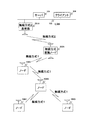
図1は、本発明の第1の実施の形態の単一の無線方式で通信する位置検出システムのブロック図である。
(First embodiment)
FIG. 1 is a block diagram of a position detection system that performs communication by a single wireless system according to a first embodiment of this invention.

単一の無線方式で通信する位置検出システムは、サーバ101、クライアント104、無線方式1の基地局107及びノード108A、108B、108C、108Dを備える。   A position detection system that communicates by a single wireless system includes a server 101, a client 104, a base station 107 of wireless system 1, and nodes 108A, 108B, 108C, and 108D.

無線方式1の基地局107は、一つを図示しているが、複数備えられていてもよい。また、ノード108A等は、4つを図示しているが、いくつ備えられていてもよい。   Although one base station 107 of the wireless system 1 is illustrated, a plurality of base stations 107 may be provided. Further, although four nodes 108A and the like are illustrated, any number may be provided.

ノード108A等は、無線方式1を用いて、互いに通信する。また、無線方式1の基地局107と当該基地局107の通信範囲に存在するノード108Aとは、無線方式1を用いて、互いに通信する。つまり、本説明図において、ノード108Aは、単一の無線方式1を用いて、他のノード108B等及び無線方式1の基地局107と通信する。   The nodes 108A and the like communicate with each other using the wireless method 1. Further, the base station 107 of the wireless system 1 and the node 108A existing in the communication range of the base station 107 communicate with each other using the wireless system 1. That is, in this explanatory diagram, the node 108 </ b> A communicates with the other nodes 108 </ b> B and the base station 107 of the wireless method 1 using a single wireless method 1.

無線方式1の基地局107、サーバ101及びクライアント104は、LAN106を介して、互いに接続されている。   The wireless system 1 base station 107, server 101, and client 104 are connected to each other via a LAN 106.

ノード108A等は、図3で後述するが、センサを用いて、各種情報を測定する。そして、ノード108A等は、測定した情報を、他のノード108A等及び無線方式1の基地局107を介して、サーバ101に送信する。   As will be described later with reference to FIG. 3, the node 108A and the like measure various information using sensors. Then, the node 108A or the like transmits the measured information to the server 101 via the other node 108A or the like and the base station 107 of the wireless system 1.

例えば、ノード108Dは、ノード108B、ノード108A、無線方式1の基地局107を介して、サーバ101に情報を送信する。   For example, the node 108D transmits information to the server 101 via the node 108B, the node 108A, and the base station 107 of the wireless system 1.

無線方式1の基地局107は、ノード108A等から受信した情報を、サーバ101に転送する。   The base station 107 of the wireless system 1 transfers information received from the node 108A or the like to the server 101.

サーバ101は、図6で後述するが、ノード位置情報データ102及びセンサデータ103を管理する。具体的には、サーバ101は、後述する方法によって、ノード108A等の位置を求める。そして、求めたノード108A等の位置を、ノード位置情報データ102に格納する。また、サーバ101は、ノード108A等がセンサを用いて測定した情報を受信する。そして、受信した情報をセンサデータ103に格納する。   As will be described later with reference to FIG. 6, the server 101 manages the node position information data 102 and the sensor data 103. Specifically, the server 101 obtains the position of the node 108A or the like by a method described later. Then, the obtained position of the node 108A or the like is stored in the node position information data 102. In addition, the server 101 receives information measured by the node 108A or the like using a sensor. The received information is stored in the sensor data 103.

サーバ101は、ノード位置情報データ102及びセンサデータ103を併せて管理することによって、ノード108A等で測定された情報とノード108A等の位置との連携を図ることができる。   The server 101 can manage the node position information data 102 and the sensor data 103 together to link information measured by the node 108A and the position of the node 108A and the like.

更に、サーバ101は、ノード108A等のバッテリの状態を監視する。そして、監視したバッテリの状態に応じて、ノード108Aの位置を求める際に用いる測位方法を決定する。   Furthermore, the server 101 monitors the state of a battery such as the node 108A. And the positioning method used when calculating | requiring the position of node 108A is determined according to the state of the monitored battery.

クライアント104は、ノード位置情報データ102及びセンサデータ103をサーバ101から取得する。そして、取得したノード位置情報データ102及びセンサデータ103を用いて、センサデータ利用アプリケーション105を実行する。   The client 104 acquires node position information data 102 and sensor data 103 from the server 101. Then, the sensor data utilization application 105 is executed using the acquired node position information data 102 and sensor data 103.

図2は、本発明の第1の実施の形態の複数の無線方式で通信する位置検出システムのブロック図である。   FIG. 2 is a block diagram of a position detection system that performs communication using a plurality of wireless systems according to the first embodiment of this invention.

複数の無線方式で通信する位置検出システムは、サーバ101、クライアント104、無線方式2の基地局201A、無線方式変換ノード202A及びノード108A、108B、108C、108Dを含む。   The position detection system that communicates with a plurality of wireless systems includes a server 101, a client 104, a wireless system 2 base station 201A, a wireless system conversion node 202A, and nodes 108A, 108B, 108C, and 108D.

サーバ101、クライアント104及びノード108A等は、単一の無線方式で通信する位置検出システム(図1)の構成と同一である。よって、同一の構成には同一の番号を付し、説明を省略する。   The server 101, the client 104, the node 108A, and the like have the same configuration as the position detection system (FIG. 1) that communicates using a single wireless method. Therefore, the same number is attached | subjected to the same structure and description is abbreviate | omitted.

無線方式2の基地局201A及び無線方式変換ノード202Aは、それぞれ一つを図示しているが、複数備えられていてもよい。また、ノード108A等は、4つを図示しているが、いくつ備えられていてもよい。   One base station 201A and two wireless system conversion nodes 202A in the wireless system 2 are illustrated, but a plurality of base stations 201A and wireless system conversion nodes 202A may be provided. Further, although four nodes 108A and the like are illustrated, any number may be provided.

ノード108A等は、無線方式1を用いて、互いに通信する。また、無線方式変換ノード202Aと当該無線方式変換ノード202Aの通信範囲に存在するノード108Aとは、無線方式1を用いて、互いに通信する。無線方式2の基地局201Aと無線方式変換ノード202Aとは、無線方式2を用いて、互いに通信する。   The nodes 108A and the like communicate with each other using the wireless method 1. Further, the wireless method conversion node 202A and the node 108A existing in the communication range of the wireless method conversion node 202A communicate with each other using the wireless method 1. The radio system 2 base station 201 </ b> A and the radio system conversion node 202 </ b> A communicate with each other using the radio system 2.

無線方式2の基地局201A、サーバ101及びクライアント104は、LAN106を介して、互いに接続されている。   The base station 201 </ b> A, the server 101, and the client 104 of the wireless system 2 are connected to each other via the LAN 106.

無線方式変換ノード202Aは、図4で後述するが、ノード108A等から受信した無線方式1の情報を、無線方式2に変換する。そして、変換した情報を、無線方式2の基地局202Aに送信する。   As will be described later with reference to FIG. 4, the wireless system conversion node 202A converts the wireless system 1 information received from the node 108A or the like into the wireless system 2. Then, the converted information is transmitted to the base station 202A of the wireless system 2.

無線方式2の基地局201Aは、図5で後述するが、無線方式変換ノード202Aから受信した情報をサーバ101に送信する。   As will be described later with reference to FIG. 5, the base station 201A of the wireless system 2 transmits information received from the wireless system conversion node 202A to the server 101.

無線方式変換ノード202Aと無線方式2の基地局201Aとは、無線方式1より通信距離の長い無線方式2で、互いに通信する。そのため、複数の無線方式で通信する位置検出システムは、ノード108A等からサーバ101へ情報を送信する際に経由するノード108A等の数を減らすことができる。よって、複数の無線方式で通信する位置検出システムは、広いエリアに適用する場合に特に有効である。   Radio system conversion node 202A and radio system 2 base station 201A communicate with each other using radio system 2 having a longer communication distance than radio system 1. Therefore, a position detection system that communicates with a plurality of wireless systems can reduce the number of nodes 108A and the like that are routed when information is transmitted from the nodes 108A and the like to the server 101. Therefore, a position detection system that communicates with a plurality of wireless systems is particularly effective when applied to a wide area.

以下、複数の無線方式で通信する位置検出システム(図2)を例として、第1の実施の形態を説明する。但し、無線方式2の基地局201Aを無線方式1の基地局107に置き換え、更に、無線方式変換ノード202Aをノード108A等に置き換えれば、単一の無線方式で通信する位置検出システム(図1)に対しても第1の実施の形態を適用できる。   Hereinafter, the first embodiment will be described by taking a position detection system (FIG. 2) that performs communication by a plurality of wireless systems as an example. However, if the base station 201A of the wireless system 2 is replaced with the base station 107 of the wireless system 1, and the wireless system conversion node 202A is replaced with the node 108A or the like, a position detection system that performs communication by a single wireless system (FIG. 1) The first embodiment can also be applied to.

図3に、本発明の第1の実施の形態のノード108Aのブロック図である。   FIG. 3 is a block diagram of the node 108A according to the first embodiment of this invention.

ノード108Aは、アンテナ2301、無線方式1の送信部2302、無線方式1の受信部2303、受信電力測定部2304、制御部2305、バッテリ状態測定部2306、バッテリ2307、センサ情報測定部2308、センサ2309、送信出力制御部2310、観測信号送信部2311及び観測信号受信部2312を備える。   The node 108A includes an antenna 2301, a wireless system 1 transmitting unit 2302, a wireless system 1 receiving unit 2303, a received power measuring unit 2304, a control unit 2305, a battery state measuring unit 2306, a battery 2307, a sensor information measuring unit 2308, and a sensor 2309. , A transmission output control unit 2310, an observation signal transmission unit 2311, and an observation signal reception unit 2312.

アンテナ2301は、無線方式1のアナログ信号を送受信する。   The antenna 2301 transmits and receives an analog signal of the wireless method 1.

無線方式1の送信部2302は、無線方式1の符号化処理及び無線方式1の変調処理を行なった後、変調されたデジタル信号を無線方式1のアナログ信号に変換する。   The wireless system 1 transmission unit 2302 performs wireless system 1 encoding processing and wireless system 1 modulation processing, and then converts the modulated digital signal into a wireless system 1 analog signal.

無線方式1の受信部2303は、アンテナ2301から受信した無線方式1のアナログ信号をデジタル信号に変換して、無線方式1の復調処理及び無線方式1の復号処理を行うことによって、送信された信号を復元する。   The reception unit 2303 of the wireless system 1 converts the analog signal of the wireless system 1 received from the antenna 2301 into a digital signal, and performs the demodulation process of the wireless system 1 and the decoding process of the wireless system 1 to transmit the transmitted signal To restore.

受信電力測定部2304は、アンテナ2301から受信した無線方式1の信号の受信電力を測定する。なお、受信電力測定部2304は、第2の実施の形態で使用される構成であり、本実施の形態では省略できる。   The received power measuring unit 2304 measures the received power of the radio system 1 signal received from the antenna 2301. The received power measuring unit 2304 has the configuration used in the second embodiment, and can be omitted in this embodiment.

バッテリ2307は、ノード108Aに電力を供給する。なお、ノード108Aは、バッテリ2307の代わりに、電源回路が備えられていてもよい。電源回路は、ノード108Aの外部の電源と有線によって接続し、外部の電源から入力された電力をノード108Aに供給する。   The battery 2307 supplies power to the node 108A. Note that the node 108A may include a power supply circuit instead of the battery 2307. The power supply circuit is connected to a power supply external to the node 108A by a wire, and supplies power input from the external power supply to the node 108A.

バッテリ状態測定部2306は、バッテリ2307の状態を測定する。バッテリ2307の状態には、バッテリ2307の出力電圧、バッテリ2307の交換日及び/又はバッテリ2307の累積消費量等が含まれる。   The battery state measurement unit 2306 measures the state of the battery 2307. The state of the battery 2307 includes an output voltage of the battery 2307, a replacement date of the battery 2307, and / or a cumulative consumption amount of the battery 2307.

センサ2309は、ノード108Aの周辺の情報を測定する。センサ情報測定部2308は、センサ2309が測定した情報を加工処理する。加工処理では、例えば、時間平均や移動平均、閾値判定による測定情報の取捨選択などを行う。   The sensor 2309 measures information around the node 108A. A sensor information measuring unit 2308 processes information measured by the sensor 2309. In the processing, for example, selection of measurement information by time average, moving average, or threshold determination is performed.

制御部2305は、ノード108Aの全体を制御する。例えば、制御部2305は、サーバ101との通信のプロトコル処理等を行う。   The control unit 2305 controls the entire node 108A. For example, the control unit 2305 performs protocol processing for communication with the server 101.

観測信号送信部2311は、ノード108Aの外部に観測信号を送信する。なお、観測信号は、ノード108A等の測位に用いる信号である。送信出力制御部2310は、観測信号送信部2311が送信する観測信号の送信出力を制御する。   The observation signal transmission unit 2311 transmits an observation signal to the outside of the node 108A. The observation signal is a signal used for positioning of the node 108A and the like. The transmission output control unit 2310 controls the transmission output of the observation signal transmitted by the observation signal transmission unit 2311.

観測信号受信部2312は、ノード108Aの外部から観測信号を受信する。   The observation signal receiving unit 2312 receives an observation signal from the outside of the node 108A.

なお、他のノード108B等の構成も、ノード108Aと同一である。よって、説明を省略する。   The configuration of the other node 108B and the like is the same as that of the node 108A. Therefore, the description is omitted.

図4は、本発明の第1の実施の形態の無線方式変換ノード202Aのブロック図である。   FIG. 4 is a block diagram of the radio system conversion node 202A according to the first embodiment of this invention.

無線方式変換ノード202Aは、アンテナ2401、切替スイッチ2402、無線方式1の送信部2403、無線方式1の受信部2404、受信電力測定部2405、無線方式2の送信部2406、無線方式2の受信部2407、制御部2408、バッテリ状態測定部2409、バッテリ2410、送信出力制御部2411、観測信号送信部2412及び観測信号受信部2413を備える。   The radio system conversion node 202A includes an antenna 2401, a changeover switch 2402, a radio system 1 transmission unit 2403, a radio system 1 reception unit 2404, a received power measurement unit 2405, a radio system 2 transmission unit 2406, and a radio system 2 reception unit. 2407, a control unit 2408, a battery state measurement unit 2409, a battery 2410, a transmission output control unit 2411, an observation signal transmission unit 2412, and an observation signal reception unit 2413.

アンテナ2401は、無線方式1のアナログ信号及び無線方式2のアナログ信号を送受信する。   The antenna 2401 transmits and receives an analog signal of the wireless system 1 and an analog signal of the wireless system 2.

切替スイッチ2402は、無線方式1のアナログ信号と無線方式2のアナログ信号とを切り替える。   The change-over switch 2402 switches between a wireless method 1 analog signal and a wireless method 2 analog signal.

切替スイッチ2402は、例えば、無線方式1と無線方式2が同一の周波数帯域を利用する場合は、時間でスイッチを切替える。異なる周波数帯域を利用する場合はフィルタによって分離する。   For example, when the wireless system 1 and the wireless system 2 use the same frequency band, the changeover switch 2402 switches the switch over time. If different frequency bands are used, they are separated by a filter.

また、アンテナ2401を無線方式1用のアンテナと、無線方式2用のアンテナを別々に持つことによって、切替スイッチ2402を不要とする構成でもよい。   Alternatively, the antenna 2401 may have a wireless system 1 antenna and a wireless system 2 antenna separately, thereby eliminating the need for the changeover switch 2402.

無線方式1の送信部2403は、無線方式1の符号化処理及び無線方式1の変調処理を行った後、変調されたデジタル信号を無線方式1のアナログ信号に変換する。   The wireless system 1 transmitter 2403 performs the wireless system 1 encoding process and the wireless system 1 modulation process, and then converts the modulated digital signal into the wireless system 1 analog signal.

無線方式1の受信部2404は、アンテナ2401から受信した無線方式1のアナログ信号をデジタル信号に変換して、無線方式1の復調処理及び無線方式1の復号処理を行うことによって、送信された信号を復元する。   The reception unit 2404 of the wireless system 1 converts the analog signal of the wireless system 1 received from the antenna 2401 into a digital signal and performs the demodulation process of the wireless system 1 and the decoding process of the wireless system 1 to transmit the transmitted signal To restore.

受信電力測定部2405は、アンテナ2401から受信した無線方式1の信号の受信電力を測定する。なお、受信電力測定部2405は、第2の実施の形態で使用される構成であり、本実施の形態では省略できる。   A received power measurement unit 2405 measures the received power of the wireless method 1 signal received from the antenna 2401. The received power measurement unit 2405 is a configuration used in the second embodiment, and can be omitted in this embodiment.

無線方式2の送信部2406は、無線方式2の符号化処理及び無線方式2の変調処理を行った後、変調されたデジタル信号を無線方式2のアナログ信号に変換する。   The wireless system 2 transmission unit 2406 performs wireless system 2 encoding processing and wireless system 2 modulation processing, and then converts the modulated digital signal into a wireless system 2 analog signal.

無線方式2の受信部2407は、アンテナ2401から受信した無線方式2のアナログ信号をデジタル信号に変換して、無線方式2の復調処理及び無線方式2の復号処理を行うことによって、送信された信号を復元する。   The radio system 2 receiving unit 2407 converts the radio system 2 analog signal received from the antenna 2401 into a digital signal, performs radio system 2 demodulation processing and radio system 2 decoding processing, and transmits the transmitted signal. To restore.

バッテリ2410は、無線方式変換ノード202Aに電力を供給する。なお、無線方式変換ノード202Aは、バッテリ2410の代わりに、電源回路が備えられていてもよい。電源回路は、無線方式変換ノード202Aの外部の電源と有線によって接続し、外部の電源から入力された電力を無線方式変換ノード202Aに供給する。   The battery 2410 supplies power to the wireless system conversion node 202A. Note that the wireless system conversion node 202A may include a power supply circuit instead of the battery 2410. The power supply circuit is connected to a power supply external to the wireless system conversion node 202A by wire, and supplies power input from the external power supply to the wireless system conversion node 202A.

バッテリ状態測定部2409は、バッテリ2410の状態を測定する。なお、バッテリ2410の状態は、バッテリ2410の出力電圧、バッテリ2410の交換日及び/又はバッテリ2410の累積消費量等を含む。   The battery state measurement unit 2409 measures the state of the battery 2410. Note that the state of the battery 2410 includes an output voltage of the battery 2410, a replacement date of the battery 2410, and / or a cumulative consumption amount of the battery 2410.

観測信号送信部2412は、無線方式変換ノード202Aの外部に観測信号を送信する。送信出力制御部2411は、観測信号送信部2412が送信する観測信号の送信出力を制御する。   The observation signal transmission unit 2412 transmits an observation signal to the outside of the radio system conversion node 202A. The transmission output control unit 2411 controls the transmission output of the observation signal transmitted by the observation signal transmission unit 2412.

観測信号受信部2413は、無線方式変換ノード202Aの外部から観測信号を受信する。   The observation signal receiving unit 2413 receives an observation signal from the outside of the radio system conversion node 202A.

制御部2408は、無線方式変換ノード202Aの全体を制御する。例えば、制御部2408は、サーバ101との通信のプロトコル処理を行う。また、制御部2408は、無線方式2の受信部2407から受けたデジタル信号を無線方式1の信号フォーマットに変換してから、無線方式1の送信部2403に転送する。同様に、無線方式1の受信部2404から受けたデジタル信号を無線方式2の信号フォーマットに変換してから、無線方式2の送信部2406に転送する。   The control unit 2408 controls the entire radio system conversion node 202A. For example, the control unit 2408 performs protocol processing for communication with the server 101. Further, the control unit 2408 converts the digital signal received from the reception unit 2407 of the wireless method 2 into a signal format of the wireless method 1 and then transfers the digital signal to the transmission unit 2403 of the wireless method 1. Similarly, the digital signal received from the wireless system 1 receiving unit 2404 is converted into the wireless system 2 signal format, and then transferred to the wireless system 2 transmitting unit 2406.

なお、他の無線方式変換ノード202B等の構成も、無線方式変換ノード202Aと同一である。よって、説明を省略する。   The configuration of the other radio system conversion node 202B and the like is the same as that of the radio system conversion node 202A. Therefore, the description is omitted.

図5は、本発明の第1の実施の形態の無線方式2の基地局201Aのブロック図である。   FIG. 5 is a block diagram of the base station 201A of the wireless system 2 according to the first embodiment of this invention.

無線方式2の基地局201Aは、アンテナ2501、無線方式2の送信部2502、無線方式2の受信部2503、受信電力測定部2504、制御部2505、電源回路2506、有線送信部2507、有線受信部2508、送信出力制御部2509、観測信号送信部2510及び観測信号受信部2511を備える。   The wireless system 2 base station 201A includes an antenna 2501, a wireless system 2 transmission unit 2502, a wireless system 2 reception unit 2503, a received power measurement unit 2504, a control unit 2505, a power supply circuit 2506, a wired transmission unit 2507, and a wired reception unit. 2508, a transmission output control unit 2509, an observation signal transmission unit 2510, and an observation signal reception unit 2511.

アンテナ2501は、無線方式2のアナログ信号を送受信する。   The antenna 2501 transmits and receives an analog signal of the wireless method 2.

無線方式2の送信部2502は、無線方式2の符号化処理及び無線方式2の変調処理を行った後、変調されたデジタル信号を無線方式2のアナログ信号に変換する。   The wireless system 2 transmission unit 2502 performs wireless system 2 encoding processing and wireless system 2 modulation processing, and then converts the modulated digital signal into a wireless system 2 analog signal.

無線方式2の受信部2503は、アンテナ2501から受信した無線方式2のアナログ信号をデジタル信号に変換して、無線方式2の復調処理及び無線方式2の復号処理を行うことによって、送信された信号を復元する。   The radio system 2 receiving unit 2503 converts the radio system 2 analog signal received from the antenna 2501 into a digital signal, performs radio system 2 demodulation processing and radio system 2 decoding processing, and transmits the transmitted signal. To restore.

受信電力測定部2504は、アンテナ2501から受信した無線方式2の信号の受信電力を測定する。なお、受信電力測定部2504は、第2の実施の形態で使用される構成であり、本実施の形態では省略できる。   The received power measurement unit 2504 measures the received power of the radio system 2 signal received from the antenna 2501. The received power measurement unit 2504 is a configuration used in the second embodiment, and can be omitted in this embodiment.

制御部2505は、無線方式2の基地局201Aの全体を制御する。例えば、制御部2505は、サーバ101との通信のプロトコル処理を行う。   The control unit 2505 controls the entire base station 201A of the wireless system 2. For example, the control unit 2505 performs protocol processing for communication with the server 101.

電源回路2506は、無線方式2の基地局201Aの外部の電源と有線によって接続し、外部の電源から入力された電力を無線方式2の基地局201Aに供給する。なお、無線方式2の基地局201Aは、電源回路2506の代わりに、バッテリが備えられていてもよい。   The power supply circuit 2506 is connected to an external power source of the base station 201A of the wireless system 2 by wire, and supplies power input from the external power source to the base station 201A of the wireless system 2. Note that the radio system 2 base station 201 </ b> A may include a battery instead of the power supply circuit 2506.

有線送信部2507は、LAN106を介して、サーバ101等に情報を送信する。有線受信部2508は、LAN106を介して、サーバ101等から情報を受信する。   A wired transmission unit 2507 transmits information to the server 101 or the like via the LAN 106. A wired receiving unit 2508 receives information from the server 101 or the like via the LAN 106.

観測信号送信部2510は、無線方式2の基地局201Aの外部に観測信号を送信する。送信出力制御部2509は、観測信号送信部2510が送信する観測信号の送信出力を制御する。   The observation signal transmission unit 2510 transmits an observation signal to the outside of the radio system 2 base station 201A. The transmission output control unit 2509 controls the transmission output of the observation signal transmitted by the observation signal transmission unit 2510.

観測信号受信部2511は、無線方式2の基地局201Aの外部から観測信号を受信する。   The observation signal receiving unit 2511 receives an observation signal from the outside of the base station 201A of the wireless method 2.

なお、他の無線方式2の基地局201B等の構成も、無線方式2の基地局201Aと同一である。よって説明を省略する。   The configuration of the other radio system 2 base station 201B and the like is the same as that of the radio system 2 base station 201A. Therefore, the description is omitted.

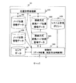
図6は、本発明の第1の実施の形態のサーバ101のブロック図である。   FIG. 6 is a block diagram of the server 101 according to the first embodiment of this invention.

サーバ101は、制御部1306、位置計算処理部1401及び記憶部を備える。   The server 101 includes a control unit 1306, a position calculation processing unit 1401, and a storage unit.

記憶部は、ノード位置情報データ102、センサデータ103、無線方式変換ノード位置情報データ1402、システム管理ポリシー1403、ノード状態管理データ1404及び無線方式変換ノード状態管理データ1405をデータベースとして記憶している。   The storage unit stores node position information data 102, sensor data 103, wireless system conversion node position information data 1402, system management policy 1403, node state management data 1404, and wireless system conversion node state management data 1405 as a database.

ノード位置情報データ102には、ノード108A等の測位の結果が格納される。ノード状態管理データ1404には、ノード108A等の状態に関する情報が格納される。ノード108A等の状態は、ノード108A等のバッテリ2307の状態を含む。   The node position information data 102 stores the positioning result of the node 108A and the like. The node state management data 1404 stores information related to the state of the node 108A and the like. The state of the node 108A and the like includes the state of the battery 2307 such as the node 108A.

センサデータ103には、ノード108A等のセンサ2309によって測定された情報が格納される。   The sensor data 103 stores information measured by the sensor 2309 such as the node 108A.

無線方式変換ノード位置情報データ1402には、無線方式変換ノード202A等の測位の結果が格納される。   The wireless system conversion node position information data 1402 stores the positioning results of the wireless system conversion node 202A and the like.

無線方式変換ノード状態管理データ1405には、無線方式変換ノード202A等の状態に関する情報が格納される。無線方式変換ノード202A等の状態には、無線方式変換ノード202A等のバッテリ2410の状態を含む。   The wireless system conversion node state management data 1405 stores information on the state of the wireless system conversion node 202A and the like. The state of the wireless system conversion node 202A and the like includes the state of the battery 2410 of the wireless system conversion node 202A and the like.

システム管理ポリシー1403には、ノード108A等及び無線方式変換ノード202A等の測位方法を決定する方針が格納される。   The system management policy 1403 stores a policy for determining positioning methods such as the node 108A and the radio system conversion node 202A.

制御部1406は、サーバ101の全体を制御する。例えば、制御部1406は、ノード108A等、無線方式変換ノード202A等及び無線方式2の基地局201A等との通信のプロトコル処理を行う。また、制御部1406は、ノード108A等、無線方式変換ノード202A等及び無線方式2の基地局201Aから受信した情報を記憶部に格納する。また、制御部1406は、システム管理ポリシー1403に基づいて、ノード108A等及び無線方式変換ノード202A等の測位方法を決定する。   The control unit 1406 controls the entire server 101. For example, the control unit 1406 performs protocol processing for communication with the node 108A and the like, the radio system conversion node 202A and the like, and the radio system 2 base station 201A and the like. Also, the control unit 1406 stores information received from the node 108A, the radio system conversion node 202A, etc., and the radio system 2 base station 201A in the storage unit. Further, the control unit 1406 determines positioning methods such as the node 108A and the radio system conversion node 202A based on the system management policy 1403.

位置計算処理部1401は、ノード108A等及び無線方式変換ノード202A等から受信した情報に基づいて、ノード108A等の位置を算出する。同様に、位置計算処理部1401は、無線方式変換ノード202A等及び無線方式2の基地局201A等から受信した情報に基づいて、無線方式変換ノード202A等の位置を算出する。   The position calculation processing unit 1401 calculates the position of the node 108A or the like based on the information received from the node 108A or the like and the radio system conversion node 202A or the like. Similarly, the position calculation processing unit 1401 calculates the position of the radio system conversion node 202A or the like based on information received from the radio system conversion node 202A or the like and the base station 201A or the like of the radio system 2 or the like.

以下、無線方式変換ノード202A等及びノード108A等の位置を算出する方法について説明する。   Hereinafter, a method for calculating the positions of the wireless system conversion node 202A and the like and the node 108A and the like will be described.

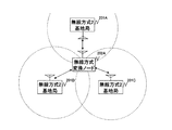
図7Aは、本発明の第1の実施の形態の位置算出方法1の説明図である。   FIG. 7A is an explanatory diagram of the position calculation method 1 according to the first embodiment of this invention.

サーバ101は、位置算出方法1を用いて、無線方式変換ノード202A等の位置を算出する。   The server 101 uses the position calculation method 1 to calculate the position of the wireless method conversion node 202A and the like.

本説明図は、無線方式変換ノード202Aを測位対象とする場合である。   This explanatory diagram is a case where the radio system conversion node 202A is a positioning target.

まず、サーバ101は、無線方式変換ノード202Aの測位方法(図11〜15で後述する。)を決定する。次に、決定した測位方法によって、無線方式変換ノード202Aと無線方式2の基地局201A、201B及び201Cとの距離をそれぞれ測定する。   First, the server 101 determines a positioning method (described later in FIGS. 11 to 15) of the wireless method conversion node 202A. Next, the distance between the radio system conversion node 202A and the radio system 2 base stations 201A, 201B, and 201C is measured by the determined positioning method.

次に、測定した距離に三辺測量の原理を用いることによって、無線方式変換ノード202Aの位置を算出する。   Next, the position of the radio system conversion node 202A is calculated by using the principle of triangulation for the measured distance.

但し、サーバ101は、無線方式2の基地局201A等の位置を予め記憶している。無線方式2の基地局201A等は、設置時に測位されてもよいし、GPS等によって所定のタイミングで測位されてもよい。   However, the server 101 stores the position of the base station 201A of the wireless system 2 in advance. The base station 201A or the like of the wireless system 2 may be positioned at the time of installation, or may be positioned at a predetermined timing by GPS or the like.

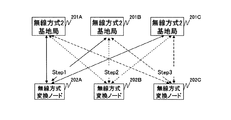
図7Bは、本発明の第1の実施の形態の位置算出方法1の説明図である。   FIG. 7B is an explanatory diagram of the position calculation method 1 according to the first embodiment of this invention.

本説明図は、無線方式変換ノード202A、202B及び202Cを測位対象とする場合である。   This explanatory diagram is a case where the radio system conversion nodes 202A, 202B and 202C are targeted for positioning.

まず、サーバ101は、無線方式変換ノード202Aと無線方式2の基地局201A、201B及び201Cとの距離をそれぞれ測定する。次に、測定した距離に三辺測量の原理を用いることによって、無線方式変換ノード202Aの位置を算出する(ステップ1)。   First, the server 101 measures the distances between the radio system conversion node 202A and the radio system 2 base stations 201A, 201B, and 201C, respectively. Next, the position of the radio system conversion node 202A is calculated by using the principle of triangulation for the measured distance (step 1).

同様に、無線方式変換ノード202Bと無線方式2の基地局201A、201B及び201Cとの距離をそれぞれ測定する。次に、測定した距離に三辺測量の原理を用いることによって、無線方式変換ノード202Bの位置を算出する(ステップ2)。   Similarly, the distances between the wireless system conversion node 202B and the wireless system 2 base stations 201A, 201B, and 201C are measured. Next, the position of the wireless system conversion node 202B is calculated by using the principle of triangulation for the measured distance (step 2).

更に、無線方式変換ノード202Cと無線方式2の基地局201A、201B及び201Cとの距離をそれぞれ測定する。次に、測定した距離に三辺測量の原理を用いることによって、無線方式変換ノード202Cの位置を算出する(ステップ3)。   Further, the distances between the radio system conversion node 202C and the radio system 2 base stations 201A, 201B, and 201C are measured. Next, the position of the radio system conversion node 202C is calculated by using the principle of triangulation for the measured distance (step 3).

サーバ101は、このような処理を繰り返すことによって、すべての無線方式変換ノード202A等の位置を算出できる。   The server 101 can calculate the positions of all the wireless system conversion nodes 202A and the like by repeating such processing.

位置算出方法1では、測位対象の無線方式変換ノード202A等が三台以上の無線方式2の基地局201A等と常に通信可能でなければならない。よって、位置算出方法1は、無線方式2の通信距離が長い場合に有効である。   In the position calculation method 1, the radio system conversion node 202A and the like to be positioned must always be able to communicate with three or more radio system 2 base stations 201A and the like. Therefore, the position calculation method 1 is effective when the communication distance of the wireless method 2 is long.

なお、サーバ101は、位置算出方法1を用いて、ノード108A等の位置を算出することもできる。この場合、無線方式2の基地局201A等を無線方式変換ノード202A等に置き換え、更に、無線方式変換ノード202A等をノード108A等に置き換える。   The server 101 can also use the position calculation method 1 to calculate the position of the node 108A or the like. In this case, the wireless system 2 base station 201A and the like are replaced with a wireless system conversion node 202A and the wireless system conversion node 202A and the like are further replaced with a node 108A and the like.

図8Aは、本発明の第1の実施の形態の位置算出方法2の説明図である。   FIG. 8A is an explanatory diagram of the position calculation method 2 according to the first embodiment of this invention.

サーバ101は、位置算出方法2を用いて、ノード108A等の位置を算出する。   The server 101 uses the position calculation method 2 to calculate the position of the node 108A and the like.

本説明図は、ノード108Aを測位対象とする場合である。   This explanatory diagram is a case where the node 108A is a positioning target.

まず、サーバ101は、ノード108Aの測位方法(図11〜15で後述する。)を決定する。次に、決定した測位方法によって、ノード108Aと無線方式変換ノード202A、202B及び202Cとの距離をそれぞれ測定する。   First, the server 101 determines a positioning method (described later in FIGS. 11 to 15) of the node 108A. Next, the distance between the node 108A and the radio system conversion nodes 202A, 202B, and 202C is measured by the determined positioning method.

次に、測定した距離に三辺測量の原理を用いることによって、ノード108Aの位置を算出する。   Next, the position of the node 108A is calculated by using the principle of triangulation for the measured distance.

但し、サーバ101は、前述した位置算出方法1によって、無線方式変換ノード202A等の位置を予め測定している。   However, the server 101 measures the position of the wireless system conversion node 202A or the like in advance by the position calculation method 1 described above.

図8Bは、本発明の第1の実施の形態の位置算出方法2の説明図である。   FIG. 8B is an explanatory diagram of the position calculation method 2 according to the first embodiment of this invention.

まず、サーバ101は、ノード108Aと無線方式変換ノード202A、202B及び202Cとの距離をそれぞれ測定する。次に、測定した距離に三辺測量の原理を用いることによって、ノード108Aの位置を算出する(ステップ4)。   First, the server 101 measures the distance between the node 108A and the radio system conversion nodes 202A, 202B, and 202C. Next, the position of the node 108A is calculated by using the principle of triangulation for the measured distance (step 4).

次に、ノード108Bとノード108A、無線方式変換ノード202A及び202Cとの距離をそれぞれ測定する。次に、測定した距離に三辺測量の原理を用いることによって、ノード108Bの位置を算出する(ステップ5)。なお、サーバ101は、ステップ4でノード108Aの位置を算出しているので、ノード108Bの位置を算出できる。   Next, the distances between the node 108B, the node 108A, and the radio system conversion nodes 202A and 202C are measured. Next, the position of the node 108B is calculated by using the principle of triangulation for the measured distance (step 5). Since the server 101 calculates the position of the node 108A in step 4, it can calculate the position of the node 108B.

次に、ノード108Cとノード108A、108B及び無線方式変換ノード202Cとの距離をそれぞれ測定する。次に、測定した距離に三辺測量の原理を用いることによって、ノード108Cの位置を算出する(ステップ6)。なお、サーバ101は、ステップ4でノード108Aの位置及びステップ5でノード108Bの位置を算出しているので、ノード108Cの位置を算出できる。   Next, the distances between the node 108C and the nodes 108A and 108B and the radio system conversion node 202C are measured. Next, the position of the node 108C is calculated by using the principle of triangulation for the measured distance (step 6). Since the server 101 calculates the position of the node 108A in step 4 and the position of the node 108B in step 5, the server 101 can calculate the position of the node 108C.

サーバ101は、このような処理を繰り返すことによって、すべてのノード108A等の位置を算出できる。   The server 101 can calculate the positions of all the nodes 108A and the like by repeating such processing.

具体的には、サーバ101は、三台以上の無線方式変換ノード202A等と通信可能なノード108A等の位置を算出する。そして、算出したノード108A等の位置を利用して、すべてのノード108A等の位置を算出する。   Specifically, the server 101 calculates the position of the node 108A and the like that can communicate with three or more wireless method conversion nodes 202A and the like. Then, using the calculated positions of the nodes 108A and the like, the positions of all the nodes 108A and the like are calculated.

位置算出方法2では、ノード108A等が三台以上の無線方式変換ノード202A等と通信可能でなくてもよい。よって、位置算出方法2は、無線方式1の通信距離が短い場合に有効である。   In the position calculation method 2, the node 108A and the like may not be able to communicate with three or more wireless method conversion nodes 202A and the like. Therefore, the position calculation method 2 is effective when the communication distance of the wireless method 1 is short.

なお、サーバ101は、位置算出方法2を用いて、無線方式変換ノード202A等の位置を算出することもできる。この場合、無線方式変換ノード202A等を無線方式2の基地局201A等に置き換え、更に、ノード108A等を無線方式変換ノード202A等に置き換える。   The server 101 can also calculate the position of the wireless system conversion node 202A or the like using the position calculation method 2. In this case, the wireless system conversion node 202A or the like is replaced with a wireless system 2 base station 201A or the like, and the node 108A or the like is replaced with a wireless system conversion node 202A or the like.

図9は、本発明の実施の形態のサーバ101のノード位置算出処理のフローチャートである。   FIG. 9 is a flowchart of node position calculation processing of the server 101 according to the embodiment of this invention.

まず、サーバ101は、前述した位置算出方法1によって、無線方式変換ノード202Aの位置を算出する(ステップ1)。同様に、位置算出方法1によって、無線方式変換ノード202Bの位置を算出する(ステップ2)。同様に、位置算出方法1によって、無線方式変換ノード202Cの位置を算出する(ステップ3)。   First, the server 101 calculates the position of the wireless method conversion node 202A by the position calculation method 1 described above (step 1). Similarly, the position calculation method 1 calculates the position of the radio system conversion node 202B (step 2). Similarly, the position calculation method 1 calculates the position of the wireless method conversion node 202C (step 3).

そして、サーバ101は、ステップ1からステップ3までの処理を所定の回数(例えば、N回)繰り返す。   Then, the server 101 repeats the processing from step 1 to step 3 a predetermined number of times (for example, N times).

サーバ101は、N回の処理で算出した位置に基づいて、それぞれの無線方式変換ノード202A等の位置を求める。例えば、N回の処理で算出した位置の平均値を、それぞれの無線方式変換ノード202A等の位置とする。   The server 101 obtains the position of each wireless method conversion node 202A or the like based on the position calculated by N processes. For example, the average value of the positions calculated by N processes is set as the position of each wireless method conversion node 202A or the like.

次に、前述した位置算出方法2によって、ノード108Aの位置を算出する(ステップ4)。このとき、算出した無線方式変換ノード202A等の位置を利用する。次に、位置算出方法2によって、ノード108Bの位置を算出する(ステップ5)。次に、位置算出方法2によって、ノード108Cの位置を算出する(ステップ6)。   Next, the position of the node 108A is calculated by the position calculation method 2 described above (step 4). At this time, the calculated position of the wireless system conversion node 202A or the like is used. Next, the position of the node 108B is calculated by the position calculation method 2 (step 5). Next, the position of the node 108C is calculated by the position calculation method 2 (step 6).

そして、サーバ101は、ステップ4からステップ6までの処理を所定の回数(例えば、M回)繰り返す。   Then, the server 101 repeats the processing from step 4 to step 6 a predetermined number of times (for example, M times).

サーバ101は、M回の処理で算出した位置に基づいて、それぞれのノード108A等の位置を求める。例えば、M回の処理で算出した位置の平均値を、それぞれのノード108A等の位置とする。   The server 101 obtains the position of each node 108A and the like based on the position calculated by the M times of processing. For example, the average value of the positions calculated by the M times of processing is set as the position of each node 108A or the like.

サーバ101は、以上のようにして、すべての無線方式変換ノード202A等及びすべてのノード108A等の位置を算出する。   As described above, the server 101 calculates the positions of all the wireless system conversion nodes 202A and the like and all the nodes 108A and the like.

しかし、サーバ101は、ノード108A等又は無線方式変換ノード202Aのいずれか一つでも位置を算出できないと、その他のノード108A等の位置も算出できなくなる。この理由を、図10で説明する。   However, if the server 101 cannot calculate the position of any one of the node 108A or the like or the wireless system conversion node 202A, the position of the other node 108A or the like cannot be calculated. The reason for this will be described with reference to FIG.

図10は、本発明の第1の実施の形態のサーバ101のノード位置算出処理の問題点の説明図である。   FIG. 10 is an explanatory diagram of a problem in the node position calculation process of the server 101 according to the first embodiment of this invention.

例えば、無線方式変換ノード202Aのバッテリ2410の出力電圧が、動作に必要な電圧を下回った場合を説明する。この場合、サーバ101は、無線方式変換ノード202Aの位置を算出できない。   For example, the case where the output voltage of the battery 2410 of the wireless system conversion node 202A is lower than the voltage necessary for the operation will be described. In this case, the server 101 cannot calculate the position of the wireless method conversion node 202A.

すると、サーバ101は、無線方式変換ノード202Aの位置が分からないので、ノード108Aの位置も算出できない。更に、サーバ101は、無線方式変換ノード202A及びノード108Aの位置が分からないので、ノード108B、108C及び108Dの位置も連鎖的に算出できなくなる。   Then, the server 101 cannot calculate the position of the node 108A because it does not know the position of the wireless method conversion node 202A. Furthermore, since the server 101 does not know the positions of the wireless system conversion node 202A and the node 108A, the positions of the nodes 108B, 108C, and 108D cannot be calculated in a chained manner.

このように、無線方式変換ノード202Aのバッテリ2410の残量が閾値を下回ると、サーバ101は、当該無線方式変換ノード202Aの位置だけでなく、ノード108A等の位置も算出できなくなってしまう。   As described above, when the remaining amount of the battery 2410 of the wireless system conversion node 202A falls below the threshold value, the server 101 cannot calculate not only the position of the wireless system conversion node 202A but also the position of the node 108A and the like.

次に、ノード108Bのバッテリ2307の出力電圧が、動作に必要な所要電圧を下回った場合を説明する。この場合、サーバ101は、ノード108Bの位置を算出できない。   Next, a case where the output voltage of the battery 2307 at the node 108B is lower than a required voltage necessary for the operation will be described. In this case, the server 101 cannot calculate the position of the node 108B.

すると、サーバ101は、ノード108Bの位置が分からないので、ノード108C及び108D位置も算出できない。   Then, since the server 101 does not know the position of the node 108B, the positions of the nodes 108C and 108D cannot be calculated.

このように、ノード108Bのバッテリ2307の残量が閾値を下回ると、サーバ101は、当該ノード108Bの位置だけでなく、当該ノード108Bの下位に位置するノード108C及び108Dの位置も算出できなくなってしまう。   Thus, when the remaining amount of the battery 2307 of the node 108B falls below the threshold value, the server 101 cannot calculate not only the position of the node 108B but also the positions of the nodes 108C and 108D positioned below the node 108B. End up.

なお、無線方式変換ノード202Aのバッテリ2410及びノード108A等のバッテリ2307の消費量は、測位方法によって異なる。   Note that the consumption of the battery 2410 of the wireless system conversion node 202A and the battery 2307 such as the node 108A varies depending on the positioning method.

以下、五つの測位方法を説明する。ここでは、無線方式変換ノード202Aを測位対象とする場合を例として説明する。しかし、無線方式2の基地局201A等を無線方式変換ノード202A等に置き換え、更に、無線方式変換ノード202Aをノード108Aに置き換えることによって、サーバ101は、ノード108Aを測位できる。   Hereinafter, five positioning methods will be described. Here, a case where the radio system conversion node 202A is a positioning target will be described as an example. However, the server 101 can measure the position of the node 108A by replacing the base station 201A or the like of the wireless system 2 with the wireless system conversion node 202A or the like and further replacing the wireless system conversion node 202A with the node 108A.

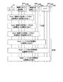
図11Aは、本発明の第1の実施の形態の測位方法1の説明図である。図11Bは、本発明の第1の実施の形態の測位方法1のシーケンス図である。   FIG. 11A is an explanatory diagram of the positioning method 1 according to the first embodiment of this invention. FIG. 11B is a sequence diagram of the positioning method 1 according to the first embodiment of this invention.

まず、サーバ101は、無線方式2の基地局201Aに、測位指示710を送信する。   First, the server 101 transmits a positioning instruction 710 to the base station 201A of the wireless system 2.

無線方式2の基地局201Aは、測位指示710を受信すると、同期信号711を送信する。このとき、無線方式2の基地局201Aは、同期信号711の送信時刻を調べ、記憶する。なお、同期信号711は、無線方式2の信号であり、送信元の一意な識別子を含む。   When receiving the positioning instruction 710, the base station 201A of the wireless system 2 transmits a synchronization signal 711. At this time, the base station 201A of the wireless system 2 checks and stores the transmission time of the synchronization signal 711. The synchronization signal 711 is a radio system 2 signal and includes a unique identifier of the transmission source.

すると、無線方式2の基地局201B、201C及び無線方式変換ノード202Aは、無線方式2の基地局201Aから、同期信号711を受信する。このとき、無線方式2の基地局201B及び201Cは、同期信号711の受信時刻を調べ、記憶する。   Then, the radio system 2 base stations 201B and 201C and the radio system conversion node 202A receive the synchronization signal 711 from the radio system 2 base station 201A. At this time, the base stations 201 </ b> B and 201 </ b> C of the wireless system 2 check and store the reception time of the synchronization signal 711.

一方、無線方式変換ノード202Aは、同期信号711を受信すると、観測信号712を送信する。観測信号712は、無線信号、音波信号又は超音波信号等であり、送信元の一意な識別子を含む。   On the other hand, upon receiving the synchronization signal 711, the wireless method conversion node 202A transmits an observation signal 712. The observation signal 712 is a wireless signal, a sound wave signal, an ultrasonic signal, or the like, and includes a unique identifier of the transmission source.

すると、無線方式2の基地局201A、201B及び201Cは、観測信号712を受信する。そして、観測信号712の受信時刻を調べ、記憶する。   Then, the base stations 201A, 201B, and 201C of the wireless system 2 receive the observation signal 712. Then, the reception time of the observation signal 712 is checked and stored.

次に、無線方式2の基地局201Aは、記憶している観測信号712の受信時刻から同期信号711の送信時刻を減算することによって、同期信号711と観測信号712の時間差を求める。また、無線方式2の基地局201B及び201Cは、記憶している観測信号712の受信時刻から同期信号711の受信時刻を減算することによって、同期信号711と観測信号712との時間差を求める。   Next, the base station 201A of the wireless system 2 obtains a time difference between the synchronization signal 711 and the observation signal 712 by subtracting the transmission time of the synchronization signal 711 from the stored reception time of the observation signal 712. Further, the base stations 201B and 201C of the wireless system 2 obtain the time difference between the synchronization signal 711 and the observation signal 712 by subtracting the reception time of the synchronization signal 711 from the stored reception time of the observation signal 712.

そして、無線方式2の基地局201A、201B及び201Cは、求めた同期信号711と観測信号712との時間差を測定情報713として、サーバ101に送信する。   Then, the base stations 201A, 201B, and 201C of the wireless system 2 transmit the obtained time difference between the synchronization signal 711 and the observation signal 712 to the server 101 as the measurement information 713.

サーバ101は、無線方式2の基地局201A、201B及び201Cから測定情報713を受信する。そして、受信した測定情報713に基づいて、無線方式変換ノード202Aの位置を算出する(701)。   The server 101 receives the measurement information 713 from the base stations 201A, 201B, and 201C of the wireless system 2. Based on the received measurement information 713, the position of the wireless method conversion node 202A is calculated (701).

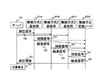
図12Aは、本発明の第1の実施の形態の測位方法2の説明図である。図12Bは、本発明の第1の実施の形態の測位方法2のシーケンス図である。   FIG. 12A is an explanatory diagram of the positioning method 2 according to the first embodiment of this invention. FIG. 12B is a sequence diagram of the positioning method 2 according to the first embodiment of this invention.

まず、サーバ101は、無線方式基地局201Aを介して、無線方式変換ノード202Aに測位指示720を送信する。   First, the server 101 transmits a positioning instruction 720 to the radio system conversion node 202A via the radio system base station 201A.

無線方式変換ノード202Aは、測位指示720を受信すると、同期信号721及び観測信号722を同時に送信する。なお、同期信号721は、無線方式2の信号であり、送信元の一意な識別子を含む。また、観測信号722は、無線信号、音波信号又は超音波信号等であり、送信元の一意な識別子を含む。   When receiving the positioning instruction 720, the wireless communication conversion node 202A transmits the synchronization signal 721 and the observation signal 722 simultaneously. The synchronization signal 721 is a radio system 2 signal and includes a unique identifier of the transmission source. The observation signal 722 is a wireless signal, a sound wave signal, an ultrasonic signal, or the like, and includes a unique identifier of the transmission source.

すると、無線方式2の基地局201A、201B及び201Cは、同期信号721及び観測信号722を受信する。このとき、無線方式2の基地局201A、201B及び201Cは、同期信号721の受信時刻及び観測信号722の受信時刻を調べ、記憶する。   Then, the base stations 201A, 201B, and 201C of the wireless system 2 receive the synchronization signal 721 and the observation signal 722. At this time, the base stations 201A, 201B, and 201C of the wireless system 2 check and store the reception time of the synchronization signal 721 and the reception time of the observation signal 722.

次に、無線方式2の基地局201A、201B及び201Cは、記憶している観測信号722の受信時刻から同期信号721の受信時刻を減算することによって、同期信号721と観測信号722との時間差を求める。そして、求めた同期信号721と観測信号722との時間差を測定情報723として、サーバ101に送信する。   Next, the base stations 201A, 201B, and 201C of the wireless system 2 subtract the reception time of the synchronization signal 721 from the stored reception time of the observation signal 722, thereby reducing the time difference between the synchronization signal 721 and the observation signal 722 Ask. Then, the obtained time difference between the synchronization signal 721 and the observation signal 722 is transmitted to the server 101 as measurement information 723.

サーバ101は、無線方式2の基地局201A、201B及び201Cから測定情報723を受信する。そして、受信した測定情報723に基づいて、無線方式変換ノード202Aの位置を算出する(701)。   The server 101 receives the measurement information 723 from the base stations 201A, 201B, and 201C of the wireless system 2. Based on the received measurement information 723, the position of the wireless method conversion node 202A is calculated (701).

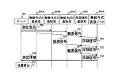
図13Aは、本発明の第1の実施の形態の測位方法3の説明図である。図13Bは、本発明の第1の実施の形態の測位方法3のシーケンス図である。   FIG. 13A is an explanatory diagram of the positioning method 3 according to the first embodiment of this invention. FIG. 13B is a sequence diagram of the positioning method 3 according to the first embodiment of this invention.

まず、サーバ101は、無線方式2の基地局201A、201B及び201Cに測位指示730を送信する。測位指示730は、同期信号731及び観測信号732の送信タイミングを含む。送信タイミングは、すべての基地局201A、201B及び201Cで同じタイミングであってもよいし。それぞれの基地局201A、201B又は201Cごとに異なるタイミングであってもよい。   First, the server 101 transmits a positioning instruction 730 to the base stations 201A, 201B, and 201C of the wireless method 2. The positioning instruction 730 includes the transmission timing of the synchronization signal 731 and the observation signal 732. The transmission timing may be the same for all base stations 201A, 201B, and 201C. The timing may be different for each base station 201A, 201B or 201C.

無線方式2の基地局201A、201B及び201Cは、測位指示730に含まれる送信タイミングで、同期信号731及び観測信号732を同時に送信する。なお、同期信号731は、無線方式2の信号であり、送信元の一意な識別子を含む。また、観測信号732は、無線信号、音波信号又は超音波信号等であり、送信元の一意な識別子を含む。   The base stations 201A, 201B, and 201C of the wireless system 2 transmit the synchronization signal 731 and the observation signal 732 at the transmission timing included in the positioning instruction 730 at the same time. The synchronization signal 731 is a radio system 2 signal and includes a unique identifier of the transmission source. The observation signal 732 is a wireless signal, a sound wave signal, an ultrasonic signal, or the like, and includes a unique identifier of the transmission source.

無線方式変換ノード202Aは、無線方式2の基地局201A、201B及び201Cから、同期信号731及び観測信号732を受信する。このとき、無線方式変換ノード202Aは、同期信号731の受信時刻及び観測信号732の受信時刻を調べ、記憶する。   The radio system conversion node 202A receives the synchronization signal 731 and the observation signal 732 from the radio system 2 base stations 201A, 201B, and 201C. At this time, the radio system conversion node 202A examines and stores the reception time of the synchronization signal 731 and the reception time of the observation signal 732.

次に、無線方式変換ノード202Aは、記憶している観測信号732の受信時刻から同期信号731の受信時刻を減算することによって、同期信号731と観測信号732との時間差を求める。なお、無線方式変換ノード202Aは、無線方式2の基地局201A、201B及び201Cのそれぞれに対して、時間差を求める。   Next, radio system conversion node 202 </ b> A obtains the time difference between synchronization signal 731 and observation signal 732 by subtracting the reception time of synchronization signal 731 from the stored reception time of observation signal 732. The radio system conversion node 202A obtains a time difference for each of the base stations 201A, 201B, and 201C of the radio system 2.

そして、無線方式変換ノード202Aは、求めた同期信号731と観測信号732との時間差を測定情報733として、サーバ101に送信する。   Then, the wireless system conversion node 202A transmits the obtained time difference between the synchronization signal 731 and the observation signal 732 as measurement information 733 to the server 101.

サーバ101は、無線方式変換ノード202Aから測定情報733を受信する。そして、受信した測定情報733に基づいて、無線方式変換ノード202Aの位置を算出する(701)。   The server 101 receives the measurement information 733 from the wireless system conversion node 202A. Based on the received measurement information 733, the position of the wireless method conversion node 202A is calculated (701).

図14Aは、本発明の第1の実施の形態の測位方法4の説明図である。図14Bは、本発明の第1の実施の形態の測位方法4のシーケンス図である。   FIG. 14A is an explanatory diagram of the positioning method 4 according to the first embodiment of this invention. FIG. 14B is a sequence diagram of the positioning method 4 according to the first embodiment of this invention.

なお、サーバ101が測位方法4を実行する場合、本実施の形態の位置検出システム(図1)は、同期信号基準局1001を備える必要がある。同期信号基準局1001は、観測信号を受信すると、同期信号を送信する。   When the server 101 executes the positioning method 4, the position detection system (FIG. 1) according to the present embodiment needs to include the synchronization signal reference station 1001. When receiving the observation signal, the synchronization signal reference station 1001 transmits a synchronization signal.

以下、測位方法4の処理を説明する。   Hereinafter, the process of the positioning method 4 will be described.

まず、無線方式変換ノード202Aは、予め設定された周期で観測信号741を送信する。なお、観測信号741は、無線信号、音波信号又は超音波信号等であり、送信元の一意な識別子を含む。   First, the radio system conversion node 202A transmits the observation signal 741 at a preset cycle. Note that the observation signal 741 is a radio signal, a sound wave signal, an ultrasonic signal, or the like, and includes a unique identifier of the transmission source.

すると、無線方式2の基地局201A、201B、201C及び同期信号基準局1001は、観測信号741を受信する。このとき、無線方式2の基地局201A、201B及び201Cは、観測信号741の受信時刻を調べ、記憶する。一方、同期信号基準局1001は、観測信号741を受信すると、同期信号742を送信する。なお、同期信号742は、無線方式2の信号であり、送信元の一意な識別子を含む。   Then, the base stations 201A, 201B, 201C and the synchronization signal reference station 1001 of the wireless system 2 receive the observation signal 741. At this time, the base stations 201A, 201B, and 201C of the wireless system 2 check and store the reception time of the observation signal 741. On the other hand, when receiving the observation signal 741, the synchronization signal reference station 1001 transmits a synchronization signal 742. The synchronization signal 742 is a radio system 2 signal and includes a unique identifier of the transmission source.

すると、無線方式2の基地局201A、201B及び201Cは、同期信号基準局1001から同期信号742を受信する。このとき、無線方式2の基地局201A、201B及び201Cは、同期信号742の受信時刻を調べ、記憶する。   Then, the base stations 201A, 201B, and 201C of the wireless system 2 receive the synchronization signal 742 from the synchronization signal reference station 1001. At this time, the base stations 201A, 201B, and 201C of the wireless method 2 check and store the reception time of the synchronization signal 742.

次に、無線方式2の基地局201A、201B及び201Cは、記憶している同期信号742の受信時刻から観測信号741の受信時刻を減算することによって、同期信号742と観測信号741との時間差を求める。そして、求めた同期信号742と観測信号741との時間差を測定情報743として、サーバ101に送信する。   Next, the base stations 201A, 201B and 201C in the wireless system 2 subtract the reception time of the observation signal 741 from the reception time of the stored synchronization signal 742, thereby reducing the time difference between the synchronization signal 742 and the observation signal 741. Ask. Then, the obtained time difference between the synchronization signal 742 and the observation signal 741 is transmitted to the server 101 as measurement information 743.

サーバ101は、無線方式2の基地局201A、201B及び201Cから測定情報743を受信する。そして、受信した測定情報743に基づいて、無線方式変換ノード202Aの位置を算出する(701)。   The server 101 receives the measurement information 743 from the base stations 201A, 201B, and 201C of the wireless system 2. Based on the received measurement information 743, the position of the wireless method conversion node 202A is calculated (701).

図15Aは、本発明の第1の実施の形態の測位方法5の説明図である。図15Bは、本発明の第1の実施の形態の測位方法5のシーケンス図である。   FIG. 15A is an explanatory diagram of the positioning method 5 according to the first embodiment of this invention. FIG. 15B is a sequence diagram of the positioning method 5 according to the first embodiment of this invention.

なお、サーバ101が測位方法5を実行する場合、本実施の形態の位置検出システム(図1)は、同期信号基準局1001を備える必要がある。   When the server 101 executes the positioning method 5, the position detection system (FIG. 1) of the present embodiment needs to include the synchronization signal reference station 1001.

以下、測位方法5の処理を説明する。   Hereinafter, the process of the positioning method 5 will be described.

まず、サーバ101は、無線方式2の基地局201A、201B及び201Cに測位指示750を送信する。測位指示750には、観測信号751の送信タイミングを含む。送信タイミングは、すべての基地局201A、201B及び201Cで同じタイミングであってもよいし。それぞれの基地局201A、201B又は201Cごとに異なるタイミングであってもよい。   First, the server 101 transmits a positioning instruction 750 to the base stations 201A, 201B, and 201C of the wireless method 2. The positioning instruction 750 includes the transmission timing of the observation signal 751. The transmission timing may be the same for all base stations 201A, 201B, and 201C. The timing may be different for each base station 201A, 201B or 201C.

無線方式2の基地局201A、201B及び201Cは、測位指示750に含まれる送信タイミングで、観測信号751を送信する。なお、観測信号751は、無線信号、音波信号又は超音波信号等であり、送信元の一意な識別子を含む。   The base stations 201A, 201B, and 201C of the wireless system 2 transmit the observation signal 751 at the transmission timing included in the positioning instruction 750. Note that the observation signal 751 is a radio signal, a sound wave signal, an ultrasonic signal, or the like, and includes a unique identifier of the transmission source.

無線方式変換ノード202A及び同期信号基準局1001は、無線方式2の基地局201A、201B及び201Cから、観測信号751を受信する。このとき、無線方式変換ノード202Aは、観測信号751の受信時刻を調べ、記憶する。一方、同期信号基準局1001は、観測信号751を受信すると、同期信号752を送信する。なお、同期信号752は、無線方式2の信号であり、送信元の一意な識別子を含む。   The radio system conversion node 202A and the synchronization signal reference station 1001 receive the observation signal 751 from the radio system 2 base stations 201A, 201B, and 201C. At this time, radio system conversion node 202A checks and stores the reception time of observation signal 751. On the other hand, when receiving the observation signal 751, the synchronization signal reference station 1001 transmits a synchronization signal 752. The synchronization signal 752 is a radio system 2 signal and includes a unique identifier of the transmission source.

すると、無線方式変換ノード202Aは、同期信号基準局1001から同期信号752を受信する。このとき、無線方式変換ノード202Aは、同期信号752の受信時刻を調べ、記憶する。   Then, the radio system conversion node 202A receives the synchronization signal 752 from the synchronization signal reference station 1001. At this time, radio system conversion node 202A checks and stores the reception time of synchronization signal 752.

無線方式変換ノード202Aは、記憶している同期信号752の受信時刻から観測信号751の受信時刻を減算することによって、同期信号752と観測信号751との時間差を求める。なお、無線方式変換ノード202Aは、無線方式2の基地局201A、201B及び201Cのそれぞれに対して、時間差を求める。   Radio system conversion node 202A calculates the time difference between synchronization signal 752 and observation signal 751 by subtracting the reception time of observation signal 751 from the stored reception time of synchronization signal 752. The radio system conversion node 202A obtains a time difference for each of the base stations 201A, 201B, and 201C of the radio system 2.

そして、無線方式変換ノード202Aは、求めた同期信号752と観測信号751との時間差を測定情報753として、サーバ101に送信する。   Then, the wireless communication conversion node 202A transmits the obtained time difference between the synchronization signal 752 and the observation signal 751 as measurement information 753 to the server 101.

サーバ101は、無線方式変換ノード202Aから測定情報753を受信する。そして、受信した測定情報753に基づいて、無線方式変換ノード202Aの位置を算出する(701)。   The server 101 receives the measurement information 753 from the radio system conversion node 202A. Based on the received measurement information 753, the position of the wireless method conversion node 202A is calculated (701).

次に、測位方法1〜5の特徴を説明する。   Next, features of the positioning methods 1 to 5 will be described.

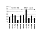
図16は、本発明の第1の実施の形態の無線方式変換ノード202A等の消費電力のグラフである。   FIG. 16 is a graph of power consumption of the wireless system conversion node 202A and the like according to the first embodiment of this invention.

本グラフは、測位対象の無線方式変換ノード202A等の単位時間当たりの消費電力(mA/sec)を示す。なお、測位対象のノード108A等の単位時間当たりの消費電力(mA/sec)も同様のグラフとなる。   This graph shows the power consumption (mA / sec) per unit time of the radio system conversion node 202A or the like to be positioned. Note that the power consumption per unit time (mA / sec) of the positioning target node 108A or the like is a similar graph.

本グラフは、以下の条件の場合である。同期信号を無線信号とし、観測信号を無線信号又は超音波信号とする。また、測位対象の無線方式変換ノード202A等は、無線信号の送信時又は無線信号の受信時に20mAの電力を消費する。また、測位対象の無線方式変換ノード202A等は、超音波信号の送信時に40mAの電力を消費し、超音波信号の受信時に10mAの電力を消費する。   This graph is for the following conditions. The synchronization signal is a radio signal, and the observation signal is a radio signal or an ultrasonic signal. Further, the radio system conversion node 202A or the like to be positioned consumes 20 mA of power when transmitting a radio signal or receiving a radio signal. Further, the wireless conversion node 202A or the like to be positioned consumes 40 mA of power when transmitting an ultrasonic signal and consumes 10 mA of power when receiving an ultrasonic signal.

本グラフによると、観測信号が無線信号である場合、測位方法4の消費電力が最も小さい。一方、観測信号が超音波信号であると、測位方法3及び測位方法5の消費電力が最も小さい。   According to this graph, when the observation signal is a radio signal, the power consumption of the positioning method 4 is the smallest. On the other hand, when the observation signal is an ultrasonic signal, the power consumption of the positioning method 3 and the positioning method 5 is the smallest.

観測信号の種類によって消費電力が異なるのは、超音波信号の送信時の消費電力が大きいことが原因である。つまり、観測信号が超音波信号の場合、測位される無線方式変換ノード202A等が超音波信号を送信しない測位方法(測位方法3及び測位方法5)の消費電力が小さい。   The reason why the power consumption differs depending on the type of observation signal is that the power consumption during transmission of the ultrasonic signal is large. That is, when the observation signal is an ultrasonic signal, the power consumption of the positioning method (positioning method 3 and positioning method 5) in which the wireless conversion node 202A or the like to be measured does not transmit the ultrasonic signal is small.

次に、サーバ101が測位指示を送信してから位置を算出するまでの時間(測位時間)を比較する。すると、測位方法3及び測位方法5は、他の測位方法の3倍以上の測位時間を要する。   Next, the time (positioning time) from when the server 101 transmits a positioning instruction until the position is calculated is compared. Then, the positioning method 3 and the positioning method 5 require a positioning time three times or more that of other positioning methods.

測位方法1、測位方法2及び測位方法4では、無線方式2の基地局201A等は、無線方式変換ノード202Aから観測信号を受信する度に、測定情報をサーバ101に送信する。一方、測位方法3及び測位方法5では、測位対象の無線方式変換ノード202Aは、周囲に存在するすべての無線方式2の基地局201A等から観測信号を受信してから、測定情報をサーバ101に送信する。このため、測位双方3及び測位方法5は、他の測位方法に比べ、測位時間を要する。   In the positioning method 1, the positioning method 2, and the positioning method 4, the base station 201A or the like of the wireless system 2 transmits measurement information to the server 101 every time it receives an observation signal from the wireless system conversion node 202A. On the other hand, in the positioning method 3 and the positioning method 5, the radio system conversion node 202A to be positioned receives observation signals from all the base stations 201A and the like of the radio system 2 existing in the surroundings, and then sends the measurement information to the server 101 Send. For this reason, both positioning 3 and positioning method 5 require positioning time compared with other positioning methods.

次に、サーバ101が算出した無線方式変換ノード202A等の位置の誤差(測定精度)を比較する。観測信号が超音波信号であると、測定精度は1〜30cmである。一方、観測信号が無線信号であると、測定精度は1〜3mである。   Next, the position error (measurement accuracy) of the wireless method conversion node 202A calculated by the server 101 is compared. When the observation signal is an ultrasonic signal, the measurement accuracy is 1 to 30 cm. On the other hand, when the observation signal is a radio signal, the measurement accuracy is 1 to 3 m.

測定精度の違いは、伝播速度の違いから生じる。無線信号の伝播速度は、超音波信号の伝播速度と比較すると、10の6乗程度速い。そのため、無線信号は、信号の受信時刻等を含む測定時間の誤差による測定精度への影響が超音波信号より大きくなる。   Differences in measurement accuracy arise from differences in propagation speed. The propagation speed of the radio signal is about 10 to the sixth power faster than the propagation speed of the ultrasonic signal. For this reason, the radio signal has a greater influence on the measurement accuracy due to an error in measurement time including the reception time of the signal than the ultrasonic signal.

以上のように、消費電力、測位時間及び測定精度等を含む特性は、測位方法と観測信号の種類との組み合わせ(測位手法)によって異なる。本実施の形態では、サーバ101は、それぞれの測位手法の特性を考慮して、無線方式変換ノード202A等又はノード108A等の測位手法を決定する。   As described above, characteristics including power consumption, positioning time, measurement accuracy, and the like vary depending on the combination of the positioning method and the type of observation signal (positioning method). In the present embodiment, the server 101 determines a positioning method such as the wireless method conversion node 202A or the node 108A or the like in consideration of the characteristics of each positioning method.

図17は、本発明の第1の実施の形態の位置検出システムの位置算出処理のシーケンス図である。   FIG. 17 is a sequence diagram of position calculation processing of the position detection system according to the first embodiment of this invention.

まず、無線方式変換ノード202A等及びノード108A等は、バッテリの状態を含む状態通知をサーバ101に送信する。なお、バッテリの状態は、バッテリの出力電圧、バッテリの交換日及び/又はバッテリの累積消費量等を含む。   First, the wireless system conversion node 202A and the like and the node 108A and the like transmit a state notification including the battery state to the server 101. The state of the battery includes a battery output voltage, a battery replacement date, and / or a cumulative battery consumption.

サーバ101は、無線方式変換ノード202A等及びノード108A等から状態通知を受信する。次に、サーバ101は、受信した状態通知に基づいて、測位手法を決定する(1301)。なお、測位手法決定処理1301については、図21で詳細を後述する。   The server 101 receives status notifications from the wireless system conversion node 202A and the like and the node 108A and the like. Next, the server 101 determines a positioning method based on the received status notification (1301). Details of the positioning method determination processing 1301 will be described later with reference to FIG.

次に、サーバ101は、決定した測位手法を、無線方式変換ノード202A等及びノード108A等に通知する。   Next, the server 101 notifies the determined positioning method to the wireless system conversion node 202A and the like and the node 108A and the like.

すると、無線方式変換ノード202A等及びノード108A等は、通知された測位手法に対応する処理を行う。そして、サーバ101は、通知した測位手法によって、無線方式変換ノード202A等又はノード108A等の位置を算出する。   Then, the radio system conversion node 202A and the like and the node 108A and the like perform processing corresponding to the notified positioning method. Then, the server 101 calculates the position of the wireless system conversion node 202A or the like or the node 108A or the like by the notified positioning method.

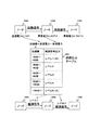
図18は、本発明の第1の実施の形態にサーバ101が備えるシステム管理ポリシー1403の説明図である。   FIG. 18 is an explanatory diagram of the system management policy 1403 included in the server 101 according to the first embodiment of this invention.

システム管理ポリシー1403は、要求目標テーブル1510及び要求重みテーブル1520を含む。   The system management policy 1403 includes a request target table 1510 and a request weight table 1520.

要求目標テーブル1510は、ノード名1511、要求測定精度1512、要求測位時間1513及びバッテリ交換要求日1514を含む。   The requested target table 1510 includes a node name 1511, requested measurement accuracy 1512, requested positioning time 1513, and battery replacement request date 1514.

ノード名1511は、無線方式変換ノード202A等又はノード108A等の一意な識別子である。   The node name 1511 is a unique identifier of the wireless system conversion node 202A or the like or the node 108A or the like.

要求測定精度1512は、当該無線方式変換ノード202A等又は当該ノード108A等の測定精度の要求目標値である。なお、測定精度は、サーバ101が算出した無線方式変換ノード202A等の位置又はノード108A等の位置の誤差である。要求測定精度1512は、予め設定された固定値であってもよいし、ユーザによって変更できてもよい。   The required measurement accuracy 1512 is a required target value of the measurement accuracy of the radio system conversion node 202A or the like or the node 108A or the like. Note that the measurement accuracy is an error in the position of the wireless system conversion node 202A or the like calculated by the server 101 or the position of the node 108A or the like. The required measurement accuracy 1512 may be a fixed value set in advance or may be changed by the user.

要求測位時間1513は、当該無線方式変換ノード202A等又は当該ノード108A等の測位時間の要求目標値である。なお、要求測位時間1513は、予め設定された固定値であってもよいし、ユーザによって変更できてもよい。   The requested positioning time 1513 is a requested target value of the positioning time of the radio system conversion node 202A or the like or the node 108A or the like. The requested positioning time 1513 may be a preset fixed value or may be changed by the user.

バッテリ交換要求日1514は、当該無線方式変換ノード202A等又は当該ノード108A等のバッテリの交換予定日の要求目標値である。なお、無線方式変換ノード202A等又はノード108A等のバッテリの交換予定日をできるだけ遅くしたい場合、バッテリ交換要求日1514には、「寿命最長」が格納される。   The battery replacement request date 1514 is a requested target value for the scheduled replacement date of the battery of the wireless system conversion node 202A or the like or the node 108A or the like. When it is desired to make the replacement date of the battery of the wireless system conversion node 202A or the like or the node 108A as late as possible, the battery replacement request date 1514 stores “longest life”.

また、交換予定日の単位は日にちに限らず、予定日の何時何分何秒までの秒単位までの時刻情報であってもよい。   Moreover, the unit of the scheduled replacement date is not limited to the date, and may be time information up to the second unit up to what hour, minute, and second on the scheduled date.

要求重みテーブル1520は、ノード名1521、測定精度の重み1522、測位時間の重み1523及びバッテリ交換予想日の重み1524を含む。   The request weight table 1520 includes a node name 1521, a measurement accuracy weight 1522, a positioning time weight 1523, and a battery replacement expected date weight 1524.

ノード名1521は、無線方式変換ノード202A等又はノード108A等の一意な識別子である。   The node name 1521 is a unique identifier of the wireless system conversion node 202A or the like or the node 108A or the like.

測定精度の重み1522は、当該無線方式変換ノード202A等又は当該ノード108A等の測定精度の要求目標値の重要度である。   The measurement accuracy weight 1522 is the importance of the required target value of the measurement accuracy of the radio system conversion node 202A or the like or the node 108A or the like.

測位時間の重み1523は、当該無線方式変換ノード202A等又は当該ノード108A等の測位時間の要求目標値の重要度である。   The positioning time weight 1523 is the importance of the required target value of the positioning time of the radio system conversion node 202A or the like or the node 108A or the like.

バッテリ交換予想日の重み1524は、当該無線方式変換ノード202A等又は当該ノード108A等のバッテリの交換予定日の要求目標値の重要度である。   The weight 1524 of the expected battery replacement date is the importance of the requested target value on the scheduled replacement date of the battery of the wireless system conversion node 202A or the like or the node 108A or the like.

なお、システム管理ポリシー1403は、更に、要求測定精度マップ1501及び要求測位時間マップ1513を含んでいてもよい。   The system management policy 1403 may further include a required measurement accuracy map 1501 and a required positioning time map 1513.

要求測定時間マップ1501は、無線方式変換ノード202A等又はノード108A等の位置と測定精度の要求目標値との対応関係を示す。   The required measurement time map 1501 shows the correspondence between the position of the wireless system conversion node 202A or the like or the node 108A and the required target value of the measurement accuracy.

サーバ101は、ノード位置情報データ102を参照して、ノード108A等の位置を判定する。次に、サーバ101は、判定したノード108A等の位置と要求測定精度マップ1501とを比較することによって、当該ノード108A等の測定精度の要求目標値を求める。そして、サーバ101は、求めた要求目標値を、要求目標テーブル1510の要求測定精度1512に格納する。   The server 101 refers to the node position information data 102 and determines the position of the node 108A and the like. Next, the server 101 compares the determined position of the node 108A or the like with the required measurement accuracy map 1501 to obtain the required target value of the measurement accuracy of the node 108A or the like. Then, the server 101 stores the calculated required target value in the required measurement accuracy 1512 of the required target table 1510.

同様に、サーバ101は、無線方式変換ノード位置情報データ1402を参照して、無線方式変換ノード202A等の位置を判定する。次に、サーバ101は、判定した無線方式変換ノード202A等の位置と要求測定精度マップ1501とを比較することによって、当該無線方式変換ノード202A等の測定精度の要求目標値を求める。そして、サーバ101は、求めた要求目標値を、要求目標テーブル1510の要求測定精度1512に格納する。   Similarly, the server 101 refers to the wireless system conversion node position information data 1402 to determine the position of the wireless system conversion node 202A and the like. Next, the server 101 compares the determined position of the wireless method conversion node 202A and the like with the required measurement accuracy map 1501 to obtain a required target value of measurement accuracy of the wireless method conversion node 202A and the like. Then, the server 101 stores the calculated required target value in the required measurement accuracy 1512 of the required target table 1510.

これによって、サーバ101は、ノード108A等の位置又は無線方式変換ノード202A等の位置に応じて、要求目標テーブル1510の要求測定精度1512を変更できる。   Accordingly, the server 101 can change the required measurement accuracy 1512 of the required target table 1510 according to the position of the node 108A or the like or the position of the wireless system conversion node 202A or the like.

要求測位時間マップ1513は、無線方式変換ノード202A等又はノード108A等の位置と測位時間の要求目標値との対応関係を示す。   The required positioning time map 1513 shows the correspondence between the position of the wireless system conversion node 202A or the like or the node 108A and the required target value of the positioning time.

サーバ101は、ノード位置情報データ102を参照して、ノード108A等の位置を判定する。次に、サーバ101は、判定したノード108A等の位置と要求測位時間マップ1502とを比較することによって、当該ノード108A等の測位時間の要求目標値を求める。そして、サーバ101は、求めた要求目標値を、要求目標テーブル1510の要求測位時間1513に格納する。   The server 101 refers to the node position information data 102 and determines the position of the node 108A and the like. Next, the server 101 compares the determined position of the node 108A or the like with the requested positioning time map 1502 to obtain the requested target value of the positioning time of the node 108A or the like. Then, the server 101 stores the obtained requested target value in the requested positioning time 1513 of the requested target table 1510.

同様に、サーバ101は、無線方式変換ノード位置情報データ1402を参照して、無線方式変換ノード202A等の位置を判定する。次に、サーバ101は、判定した無線方式変換ノード202A等の位置と要求測位時間マップ1502とを比較することによって、当該無線方式変換ノード202A等の測位時間の要求目標値を求める。そして、サーバ101は、求めた要求目標値を、要求目標テーブル1510の要求測位時間1513に格納する。   Similarly, the server 101 refers to the wireless system conversion node position information data 1402 to determine the position of the wireless system conversion node 202A and the like. Next, the server 101 compares the determined position of the wireless method conversion node 202A and the like with the required positioning time map 1502 to obtain the required target value of the positioning time of the wireless method conversion node 202A and the like. Then, the server 101 stores the obtained requested target value in the requested positioning time 1513 of the requested target table 1510.

これによって、サーバ101は、ノード108A等の位置又は無線方式変換ノード202A等の位置に応じて、要求目標テーブル1510の要求測位時間1513を変更できる。   Accordingly, the server 101 can change the requested positioning time 1513 of the requested target table 1510 according to the position of the node 108A or the like or the position of the wireless system conversion node 202A or the like.

次に、サーバ101が備える無線方式変換ノード状態管理データ1405について説明する。無線方式変換ノード状態管理データ1405は、実測状態テーブル、測位手法選択テーブル及び予測リストテーブルを含む。   Next, the wireless system conversion node state management data 1405 included in the server 101 will be described. The wireless system conversion node state management data 1405 includes an actual measurement state table, a positioning method selection table, and a prediction list table.

図19Aは、本発明の第1の実施の形態の無線方式変換ノード状態管理データ1405の実測状態テーブル1600の構成図である。   FIG. 19A is a configuration diagram of the actual measurement state table 1600 of the wireless system conversion node state management data 1405 according to the first embodiment of this invention.

実測状態テーブル1600は、無線方式変換ノード名1601、バッテリ出力1602、バッテリ交換日1603、累積消費量1604、測定精度1605及び測位時間1606を含む。   The actual measurement state table 1600 includes a wireless system conversion node name 1601, a battery output 1602, a battery replacement date 1603, a cumulative consumption 1604, a measurement accuracy 1605, and a positioning time 1606.

無線方式変換ノード名1601は、無線方式変換ノード202A等の一意な識別子である。   The radio system conversion node name 1601 is a unique identifier such as the radio system conversion node 202A.

バッテリ出力1602は、当該無線方式変換ノード202A等のバッテリ2410の出力電圧である。   The battery output 1602 is an output voltage of the battery 2410 such as the wireless system conversion node 202A.

バッテリ交換日1603は、当該無線方式変換ノード202A等のバッテリ2410が前回交換された日である。   The battery replacement date 1603 is a date on which the battery 2410 such as the wireless system conversion node 202A is replaced last time.

累積消費量1604は、当該無線方式変換ノード202A等のバッテリ2410の消費量の累積値である。   The cumulative consumption 1604 is a cumulative value of the consumption of the battery 2410 such as the wireless system conversion node 202A.

測定精度1605は、当該無線方式変換ノード202A等の前回算出された位置の誤差である。測位時間1606は、当該無線方式変換ノード202A等が前回測位された際の測位時間である。なお、測位時間は、サーバ101が測位指示を送信してから位置を算出するまでの時間である。   The measurement accuracy 1605 is an error of the previously calculated position of the wireless system conversion node 202A or the like. The positioning time 1606 is a positioning time when the wireless system conversion node 202A or the like has been positioned last time. The positioning time is the time from when the server 101 transmits a positioning instruction until the position is calculated.

サーバ101は、無線方式変換ノード202A等から、状態通知を受信すると、無線方式変換ノード状態管理データ1405の実測状態テーブル1600を更新する。   When the server 101 receives the status notification from the wireless system conversion node 202A or the like, the server 101 updates the measured state table 1600 of the wireless system conversion node state management data 1405.

具体的には、状態通知を受信した無線方式変換ノード202Aの識別子と実測状態テーブル1600の無線方式変換ノード名1601とが一致するレコードを、実測状態テーブル1600から選択する。   Specifically, a record in which the identifier of the wireless method conversion node 202A that has received the state notification matches the wireless method conversion node name 1601 of the actual state table 1600 is selected from the actual state table 1600.

次に、受信した状態通知に含まれるバッテリ2410の出力電圧を、選択したレコードのバッテリ出力1602に格納する。次に、受信した状態通知に含まれる前回のバッテリ2410の交換日を、選択したレコードのバッテリ交換日1603に格納する。次に、受信した状態通知に含まれるバッテリ2410の累積消費量を、選択したレコードの累積消費量1604に格納する。   Next, the output voltage of the battery 2410 included in the received state notification is stored in the battery output 1602 of the selected record. Next, the previous replacement date of the battery 2410 included in the received status notification is stored in the battery replacement date 1603 of the selected record. Next, the cumulative consumption amount of the battery 2410 included in the received status notification is stored in the cumulative consumption amount 1604 of the selected record.

また、サーバ101は、無線方式変換ノード202A等の位置を算出すると、無線方式変換ノード状態管理データ1405の実測状態テーブル1600を更新する。   Further, when the server 101 calculates the position of the wireless system conversion node 202A or the like, the server 101 updates the measured state table 1600 of the wireless system conversion node state management data 1405.

具体的には、位置を算出した無線方式変換ノード202Aの識別子と実測状態テーブル1600の無線方式変換ノード名1601とが一致するレコードを、実測状態テーブル1600から選択する。   Specifically, a record in which the identifier of the wireless system conversion node 202A whose position has been calculated and the wireless system conversion node name 1601 in the actual measurement state table 1600 matches is selected from the actual state table 1600.

次に、サーバ101は、求めた測定精度を、選択したレコードの測定精度1605に格納する。次に、サーバ101は、測位指示を送信してから位置を算出するまでの時間(測位時間)を求める。そして、求めた測位時間を、選択したレコードの測位時間1606に格納する。   Next, the server 101 stores the obtained measurement accuracy in the measurement accuracy 1605 of the selected record. Next, the server 101 obtains a time (positioning time) from when the positioning instruction is transmitted until the position is calculated. Then, the obtained positioning time is stored in the positioning time 1606 of the selected record.

なお、サーバ101は、無線方式変換ノード202A等の位置を算出する際に、測定精度を併せて算出する。   The server 101 also calculates the measurement accuracy when calculating the position of the wireless system conversion node 202A or the like.

また、サーバ101は、測位手法と測定精度との関係を示すテーブルを備えることによって、測位手法に対応する測定精度を求めてもよい。なお、当該テーブルに格納される測定精度は、無線方式変換ノード202A等の周囲に存在する無線方式2の基地局201A等の数等を考慮して、シミュレーションで予測した値である。   Further, the server 101 may obtain a measurement accuracy corresponding to the positioning method by providing a table indicating a relationship between the positioning method and the measurement accuracy. Note that the measurement accuracy stored in the table is a value predicted by simulation in consideration of the number of wireless system 2 base stations 201A and the like existing around the wireless system conversion node 202A and the like.

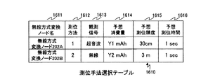
図19Bは、本発明の第1の実施の形態の無線方式変換ノード状態管理データ1405の測位手法選択テーブル1610の構成図である。   FIG. 19B is a configuration diagram of the positioning technique selection table 1610 of the wireless system conversion node state management data 1405 according to the first embodiment of this invention.

測位手法選択テーブル1610は、無線方式変換ノード名1611、測位方法1612、観測信号1613、予想消費量1614、予想測位精度1615及び予想測位時間1616を含む。   The positioning technique selection table 1610 includes a wireless system conversion node name 1611, a positioning method 1612, an observation signal 1613, an expected consumption 1614, an expected positioning accuracy 1615, and an expected positioning time 1616.

無線方式変換ノード名1611は、無線方式変換ノード202A等の一意な識別子である。   The wireless system conversion node name 1611 is a unique identifier such as the wireless system conversion node 202A.

測位方法1612は、当該無線方式変換ノード202A等の次回の測位に用いられる測位方法の識別子である。   The positioning method 1612 is an identifier of a positioning method used for the next positioning of the wireless system conversion node 202A or the like.

観測信号1613は、当該無線方式変換ノード202A等の次回の測位に用いられる観測信号の種類である。例えば、観測信号1613には、「超音波」又は「無線」が格納される。   The observation signal 1613 is the type of the observation signal used for the next positioning of the radio system conversion node 202A or the like. For example, the observation signal 1613 stores “ultrasound” or “wireless”.

予想消費量1614は、当該無線方式変換ノード202A等が次回に測位される際の消費量の予想値である。   The expected consumption 1614 is an expected value of consumption when the radio system conversion node 202A or the like is positioned next time.

予想測位精度1615は、当該無線方式変換ノード202A等が次回に測位される際の測位精度の予想値である。例えば、予想測位精度1615は、当該無線方式変換ノード202A等が次回に測位される際に使用される観測信号の種類によって、一意に決まる。なお、測位精度1615は、サーバ101が三辺測量で求めた無線方式変換ノード202A位置の誤差である。   The predicted positioning accuracy 1615 is an expected value of the positioning accuracy when the wireless system conversion node 202A or the like is positioned next time. For example, the predicted positioning accuracy 1615 is uniquely determined by the type of observation signal used when the radio system conversion node 202A or the like is positioned next time. The positioning accuracy 1615 is an error in the position of the wireless method conversion node 202A obtained by the server 101 through triangulation.

予想測位時間1616は、当該無線方式変換ノード202A等が次回に測位される際の測位時間の予想値である。   The expected positioning time 1616 is an expected value of the positioning time when the radio system conversion node 202A or the like is positioned next time.

サーバ101は、測位手法決定処理(図21)によって無線方式変換ノード202A等の測位手法を決定すると、測位手法選択テーブル1610を更新する。   When the server 101 determines a positioning method such as the wireless method conversion node 202A by the positioning method determination process (FIG. 21), the server 101 updates the positioning method selection table 1610.

具体的には、測位手法を決定した無線方式変換ノード202Aの識別子と測位手法選択テーブル1610の無線方式変換ノード名1611とが一致するレコードを、測位手法選択テーブル1610から選択する。   Specifically, a record in which the identifier of the radio system conversion node 202A that has determined the positioning method matches the radio system conversion node name 1611 of the positioning method selection table 1610 is selected from the positioning method selection table 1610.

次に、決定した測位手法の測位方法を、選択したレコードの測位方法1612に格納する。次に、決定した測位手法の観測信号の種類を、選択したレコードの観測信号1613に格納する。   Next, the positioning method of the determined positioning method is stored in the positioning method 1612 of the selected record. Next, the type of the observation signal of the determined positioning method is stored in the observation signal 1613 of the selected record.

次に、サーバ101は、決定した測位手法に基づいて、無線方式変換ノード202A等の予想消費量、予想測位精度及び予想測位時間等を求める。例えば、サーバ101は、これらの情報と測位手法との対応を示すテーブルを備えることによって、無線方式変換ノード202A等の予想消費量、予想測位精度及び予想測位時間等を一意に求めることができる。   Next, the server 101 obtains an expected consumption amount, an expected positioning accuracy, an expected positioning time, and the like of the wireless system conversion node 202A and the like based on the determined positioning method. For example, the server 101 can uniquely determine the expected consumption, the expected positioning accuracy, the expected positioning time, and the like of the wireless system conversion node 202A and the like by providing a table indicating correspondence between these pieces of information and the positioning method.

次に、求めた無線方式変換ノード202A等の予想消費量を、選択したレコードの予想消費量1614に格納する。次に、求めた無線方式変換ノード202A等の予想測位精度を、選択したレコードの予想測位精度1615に格納する。次に、求めた無線方式変換ノード202A等の予想測位時間を、選択したレコードの予想測位時間1616に格納する。   Next, the calculated expected consumption amount of the wireless system conversion node 202A or the like is stored in the expected consumption amount 1614 of the selected record. Next, the predicted positioning accuracy of the obtained wireless method conversion node 202A or the like is stored in the predicted positioning accuracy 1615 of the selected record. Next, the calculated expected positioning time of the wireless system conversion node 202A or the like is stored in the expected positioning time 1616 of the selected record.

図19Cは、本発明の第1の実施の形態の無線方式変換ノード状態管理データ1405の予測リストテーブル1620の構成図である。   FIG. 19C is a configuration diagram of the prediction list table 1620 of the wireless system conversion node state management data 1405 according to the first embodiment of this invention.

予測リスト1620は、無線方式変換ノード名1621、バッテリ交換予想日1622、予想測定精度1623及び予想測位時間1624を含む。   The prediction list 1620 includes a wireless system conversion node name 1621, an expected battery replacement date 1622, an expected measurement accuracy 1623, and an expected positioning time 1624.

無線方式変換ノード名1621は、無線方式変換ノード202A等の一意な識別子である。   The wireless system conversion node name 1621 is a unique identifier such as the wireless system conversion node 202A.

バッテリ交換予想日1622は、当該無線方式変換ノード202A等のバッテリ2410の次回の交換が予想される日である。なお、バッテリ交換予想日1622は、当該無線方式変換ノード202A等の次回の測位手法を継続した場合の予想日である。   The expected battery replacement date 1622 is a date on which the next replacement of the battery 2410 such as the wireless system conversion node 202A is expected. The expected battery replacement date 1622 is an expected date when the next positioning method such as the wireless system conversion node 202A is continued.

また、バッテリ交換予想日1622の単位は、日にちのみならず、何時何分何秒の時刻情報で秒の単位であってもよい。   The unit of the expected battery replacement date 1622 may be not only the date but also the time unit of the hour, the minute, and the second.

予想測定精度1623は、当該無線方式変換ノード202A等の次回に測位される位置の誤差の予想値である。予想測位時間1624は、当該無線方式変換ノード202A等が次回に測位される際の測位時間の予想値である。   The expected measurement accuracy 1623 is an expected value of an error in the position where the radio system conversion node 202A or the like is positioned next time. The expected positioning time 1624 is an expected value of the positioning time when the radio system conversion node 202A or the like is positioned next time.

サーバ101は、測位手法決定処理(図21)において、予測リストテーブル1620を作成する。   The server 101 creates the prediction list table 1620 in the positioning method determination process (FIG. 21).

具体的には、リストを作成する無線方式変換ノード202A等の識別子と予測リストテーブル1620の無線方式変換ノード名1621とが一致するレコードを、予測リストテーブル1620から選択する。   Specifically, a record in which the identifier of the radio system conversion node 202A or the like that creates the list matches the radio system conversion node name 1621 of the prediction list table 1620 is selected from the prediction list table 1620.

次に、リストを作成する無線方式変換ノード202A等の次回の測位手法に基づいて、当該無線方式変換ノード202A等のバッテリ2410の持続予想時間を算出する。   Next, based on the next positioning method of the radio system conversion node 202A or the like that creates the list, the expected duration of the battery 2410 of the radio system conversion node 202A or the like is calculated.

例えば、サーバ101は、以下の数式1で、無線方式変換ノード202A等のバッテリ2410の持続予想時間T(hour)を算出する。   For example, the server 101 calculates the expected duration T (hour) of the battery 2410 such as the wireless system conversion node 202A using the following formula 1.

Figure 0004568641
Figure 0004568641

なお、X(mAh)は、無線方式変換ノード202A等のバッテリ2410の容量である。また、Y(%)は、無線方式変換ノード202A等のバッテリ2410の動作効率である。また、Z(mAh)は、無線方式変換ノード202A等のバッテリ2410の累積消費量である。また、W(mA)は、無線方式変換ノード202A等のバッテリ2410の測位時の消費電流である。また、s(hour)は、無線方式変換ノード202A等の測位時間である。また、t(hour)は、無線方式変換ノード202A等の測位におけるインターバルである。I(mA)、無線方式変換ノード202A等のバッテリ2410のインターバル時の消費電流である。   X (mAh) is the capacity of the battery 2410 such as the wireless system conversion node 202A. Y (%) is the operating efficiency of the battery 2410 such as the wireless system conversion node 202A. Z (mAh) is the cumulative consumption of the battery 2410 such as the wireless system conversion node 202A. W (mA) is a current consumption during positioning of the battery 2410 such as the wireless system conversion node 202A. Further, s (hour) is a positioning time of the wireless system conversion node 202A or the like. Further, t (hour) is an interval in positioning of the radio system conversion node 202A or the like. I (mA), current consumption during the interval of the battery 2410 such as the wireless system conversion node 202A.

次に、サーバ101は、算出した持続予想時間Tに、現在の日時を足すことによって、バッテリ2410の交換予想日を求める。そして、求めた交換予想日を、予測リストテーブル1620から選択したレコードのバッテリ交換予想日1622に格納する。   Next, the server 101 calculates the expected replacement date of the battery 2410 by adding the current date and time to the calculated expected duration T. The calculated replacement date is stored in the estimated battery replacement date 1622 of the record selected from the prediction list table 1620.

他にも、サーバ101は、バッテリ2410の出力電圧の変化に基づいて、バッテリ交換予想日1622を求めてもよい。   In addition, the server 101 may obtain the expected battery replacement date 1622 based on the change in the output voltage of the battery 2410.

具体的には、サーバ101は、バッテリ2410の出力電圧と持続予想時間との関係を示すバッテリ特性テーブルを、平均消費量ごとに保持する。   Specifically, the server 101 holds a battery characteristic table indicating the relationship between the output voltage of the battery 2410 and the expected duration time for each average consumption amount.

そして、バッテリ2410の出力電圧が閾値を越えている場合、バッテリ2410の平均的な持続時間を、前回のバッテリ交換日時に足すことによって、バッテリ交換予想日1622を求める。   If the output voltage of the battery 2410 exceeds the threshold value, the expected battery replacement date 1622 is obtained by adding the average duration of the battery 2410 to the previous battery replacement date and time.

一方、バッテリ2410の出力電圧が閾値を下回ると、バッテリ特性テーブルに基づいて、バッテリ2410の持続予想時間を求める。そして、求めた持続予想時間に、現在の日時を足すことによって、バッテリ交換予想日1622を求める。   On the other hand, when the output voltage of the battery 2410 falls below the threshold, the expected duration of the battery 2410 is obtained based on the battery characteristic table. Then, the expected battery replacement date 1622 is obtained by adding the current date and time to the obtained expected duration time.

次に、サーバ101は、リストを作成する無線方式変換ノード202A等の識別子と測位手法選択テーブル1610の無線方式変換ノード名1611とが一致するレコードを、測位手法選択テーブル1610から選択する。次に、選択したレコードから、予想測位精度1615を抽出する。   Next, the server 101 selects, from the positioning method selection table 1610, a record in which the identifier of the wireless method conversion node 202A or the like that creates the list matches the wireless method conversion node name 1611 of the positioning method selection table 1610. Next, the predicted positioning accuracy 1615 is extracted from the selected record.

次に、リストを作成する無線方式変換ノード202A等の周囲に存在する無線方式2の基地局201A等の数を求める。そして、抽出した予想測位精度1615及び求めた無線方式2の基地局201A等の数に基づいて、当該無線方式変換ノード202Aの位置の誤差(測定精度)を求める。   Next, the number of radio system 2 base stations 201A and the like existing around the radio system conversion node 202A and the like for creating the list is obtained. Then, based on the extracted predicted positioning accuracy 1615 and the obtained number of base stations 201A of the wireless system 2 and the like, the position error (measurement accuracy) of the wireless system conversion node 202A is determined.

そして、求めた測定精度を、予測リストテーブル1620から選択したレコードの予想測定精度1623に格納する。   The obtained measurement accuracy is stored in the expected measurement accuracy 1623 of the record selected from the prediction list table 1620.

次に、サーバ101は、リストを作成する無線方式変換ノード202A等の前回の測位手法と次回の測位手法とが同じであるかを判定する。   Next, the server 101 determines whether the previous positioning method and the next positioning method, such as the wireless method conversion node 202A that creates the list, are the same.

測位手法が同じであると、リストを更新する無線方式変換ノード202A等の識別子と実測状態テーブル1600の無線方式変換ノード名1601とが一致するレコードを、実測状態テーブル1600から選択する。次に、選択したレコードから測位時間1606を抽出する。そして、抽出した測位時間1606を、予測リストテーブル1620から選択したレコードの予想測位時間1624に格納する。   If the positioning method is the same, a record in which the identifier of the wireless method conversion node 202A or the like whose list is to be updated matches the wireless method conversion node name 1601 of the actual state table 1600 is selected from the actual state table 1600. Next, the positioning time 1606 is extracted from the selected record. Then, the extracted positioning time 1606 is stored in the predicted positioning time 1624 of the record selected from the prediction list table 1620.

一方、測位手法が異なると、実測状態テーブル1600の情報を使うことができない。よって、リストを作成する無線方式変換ノード202A等の識別子と測位手法選択テーブル1610の無線方式変換ノード名1611とが一致するレコードを、測位手法選択テーブル1610から選択する。次に、選択したレコードから、予想測位時間1616を抽出する。そして、抽出した予想測位時間1616を、予測リストテーブル1620から選択したレコードの予想測位時間1624に格納する。   On the other hand, if the positioning method is different, the information in the actual measurement state table 1600 cannot be used. Therefore, a record in which the identifier of the radio system conversion node 202A or the like that creates the list matches the radio system conversion node name 1611 of the positioning method selection table 1610 is selected from the positioning method selection table 1610. Next, the expected positioning time 1616 is extracted from the selected record. Then, the extracted predicted positioning time 1616 is stored in the predicted positioning time 1624 of the record selected from the prediction list table 1620.

以上のように、サーバ101は、予測リストテーブル1620を作成する。   As described above, the server 101 creates the prediction list table 1620.

次に、サーバ101が備えるノード状態管理データ1404について説明する。ノード状態管理データ1404は、前述した無線方式変換ノード状態管理データ1405と同様に、実測状態テーブル、測位手法選択テーブル及び予測リストテーブルを含む。   Next, the node state management data 1404 included in the server 101 will be described. The node state management data 1404 includes an actual measurement state table, a positioning method selection table, and a prediction list table, similarly to the wireless system conversion node state management data 1405 described above.

図20Aは、本発明の第1の実施の形態のノード状態管理データ1404の実測状態テーブル1650の構成図である。   FIG. 20A is a configuration diagram of the actual measurement state table 1650 of the node state management data 1404 according to the first embodiment of this invention.

実測状態テーブル1650は、ノード名1651、バッテリ出力1652、バッテリ交換日1653、累積消費量1654、測定精度1655及び測位時間1656を含む。   The actual measurement state table 1650 includes a node name 1651, a battery output 1652, a battery replacement date 1653, an accumulated consumption 1654, a measurement accuracy 1655, and a positioning time 1656.

ノード名1651は、ノード108A等の一意な識別子である。   The node name 1651 is a unique identifier such as the node 108A.

バッテリ出力1652は、当該ノード108A等のバッテリ2307の出力電圧である。   The battery output 1652 is an output voltage of the battery 2307 such as the node 108A.

バッテリ交換日1653は、当該ノード108A等のバッテリ2307が前回交換された日である。   The battery replacement date 1653 is the date when the battery 2307 such as the node 108A was replaced last time.

累積消費量1654は、当該ノード108A等のバッテリ2307の消費量の累積値である。   The cumulative consumption 1654 is a cumulative value of the consumption of the battery 2307 such as the node 108A.

測定精度1655は、当該ノード108A等の前回算出された位置の誤差である。   The measurement accuracy 1655 is an error of the previously calculated position of the node 108A or the like.

測位時間1656は、当該ノード108A等が前回測位された際の測位時間である。なお、測位時間は、サーバ101が測位指示を送信してから位置を算出するまでの時間である。   The positioning time 1656 is a positioning time when the node 108A or the like has been positioned last time. The positioning time is the time from when the server 101 transmits a positioning instruction until the position is calculated.

サーバ101は、ノード108A等から、状態通知を受信すると、実測状態テーブル1650を更新する。なお、ノード状態管理データ1404の実測状態テーブル1650の更新の処理は、無線方式変換ノード状態管理データ1405の実測状態テーブル1600(図19A)の更新の処理と同様なので、説明を省略する。   When the server 101 receives the status notification from the node 108A or the like, the server 101 updates the actual measurement status table 1650. The update process of the actual state table 1650 of the node state management data 1404 is the same as the update process of the actual state table 1600 (FIG. 19A) of the wireless system conversion node state management data 1405, and thus the description thereof is omitted.

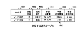
図20Bは、本発明の第1の実施の形態のノード状態管理データ1404の測位手法選択テーブル1660の構成図である。   FIG. 20B is a configuration diagram of the positioning method selection table 1660 of the node state management data 1404 according to the first embodiment of this invention.

測位手法選択テーブル1660は、ノード名1661、測位方法1662、観測信号1663、予想消費量1664、予想測位精度1665及び予想測位時間1666を含む。   The positioning method selection table 1660 includes a node name 1661, a positioning method 1662, an observation signal 1663, an expected consumption 1664, an expected positioning accuracy 1665, and an expected positioning time 1666.

ノード名1661は、ノード108A等の一意な識別子である。   The node name 1661 is a unique identifier such as the node 108A.

測位方法1662は、当該ノード108A等の次回の測位に用いられる測位方法の識別子である。観測信号1663は、当該ノード108A等の次回の測位に用いられる観測信号の種類である。例えば、観測信号1663には、「超音波」又は「無線」が格納される。   The positioning method 1662 is an identifier of a positioning method used for the next positioning of the node 108A or the like. The observation signal 1663 is the type of the observation signal used for the next positioning of the node 108A or the like. For example, the observation signal 1663 stores “ultrasound” or “wireless”.

予想消費量1664は、当該ノード108A等が次回に測位される際の消費量の予想値である。   The expected consumption 1664 is an expected value of consumption when the node 108A and the like are positioned next time.

予想測位精度1665は、当該ノード108A等が次回に測位される際の測位精度の予想値である。例えば、予想測位精度1665は、当該ノード108A等が次回に測位される際に使用される観測信号の種類によって、一意に決まる。   The predicted positioning accuracy 1665 is an expected value of the positioning accuracy when the node 108A or the like is positioned next time. For example, the predicted positioning accuracy 1665 is uniquely determined by the type of observation signal used when the node 108A or the like is positioned next time.

予想測位時間1666は、当該ノード108A等が次回に測位される際の測位時間の予想値である。   The expected positioning time 1666 is an expected value of the positioning time when the node 108A or the like is positioned next time.

サーバ101は、測位手法決定処理(図21)によってノード108A等の測位手法を決定すると、測位手法選択テーブル1660を更新する。なお、ノード状態管理データ1404の測位手法選択テーブル1660の更新の処理は、無線方式変換ノード状態管理データ1405の測位手法選択テーブル1610(図19B)の更新の処理と同様なので、説明を省略する。   When the server 101 determines the positioning method such as the node 108A by the positioning method determination process (FIG. 21), the server 101 updates the positioning method selection table 1660. Note that the update processing of the positioning method selection table 1660 of the node state management data 1404 is the same as the update processing of the positioning method selection table 1610 (FIG. 19B) of the wireless system conversion node state management data 1405, and thus the description thereof is omitted.

図20Cは、本発明の第1の実施の形態のノード状態管理データ1404の予測リストテーブル1670の構成図である。   FIG. 20C is a configuration diagram of the prediction list table 1670 of the node state management data 1404 according to the first embodiment of this invention.

予測リスト1670は、ノード名1671、バッテリ交換予想日1672、予想測定精度1673及び予想測位時間1674を含む。   The prediction list 1670 includes a node name 1671, an expected battery replacement date 1672, an expected measurement accuracy 1673, and an expected positioning time 1673.

ノード名1671は、ノード108A等の一意な識別子である。   The node name 1671 is a unique identifier such as the node 108A.

バッテリ交換予想日1672は、当該ノード108A等のバッテリ2307の次回の交換が予想される日である。なお、バッテリ交換予想日1672は、当該ノード108A等の次回の測位手法を継続した場合の予想日である。   The expected battery replacement date 1672 is a date when the next replacement of the battery 2307 such as the node 108A is expected. The expected battery replacement date 1672 is an expected date when the next positioning method for the node 108A or the like is continued.

また、バッテリ交換予想日1672の単位は、日にちのみならず、何時何分何秒の時刻情報で秒の単位であってもよい。   Further, the unit of the expected battery replacement date 1672 may be not only the date, but also the time unit of the hour, the minute, and the second.

予想測定精度1673は、当該ノード108A等の次回に測位される位置の誤差の予想値である。予想測位時間1674は、当該ノード108A等が次回に測位される際の測位時間の予想値である。   The expected measurement accuracy 1673 is an expected value of the error of the position where the node 108A or the like is positioned next time. The expected positioning time 1673 is an expected value of the positioning time when the node 108A or the like is positioned next time.

サーバ101は、測位手法決定処理(図21)において、予測リストテーブル1670を更新する。なお、ノード状態管理データ1404の予測リストテーブル1670の更新の処理は、無線方式変換ノード状態管理データ1405の測位手法選択テーブル1620(図19C)の更新の処理と同様なので、説明を省略する。   The server 101 updates the prediction list table 1670 in the positioning method determination process (FIG. 21). The update process of the prediction list table 1670 of the node state management data 1404 is the same as the update process of the positioning method selection table 1620 (FIG. 19C) of the wireless system conversion node state management data 1405, and thus the description thereof is omitted.

図21は、本発明の第1の実施の形態におけるサーバ101の測位手法決定処理のフローチャートである。   FIG. 21 is a flowchart of the positioning method determination process of the server 101 according to the first embodiment of this invention.

以下、ノード108A等の測位手法を決定する場合を例として説明するが、無線方式変換ノード202Aの測位手法を決定する場合も同様の処理である。   Hereinafter, the case where the positioning method of the node 108A or the like is determined will be described as an example, but the same processing is performed when the positioning method of the wireless method conversion node 202A is determined.

まず、サーバ101は、ノード108A等を一つずつ順に選択する(1701)。   First, the server 101 sequentially selects the nodes 108A and the like one by one (1701).

次に、選択したノード108A等に関する要求目標及び要求重みを、システム管理ポリシー1403(図18)から抽出する。   Next, the request target and request weight regarding the selected node 108A and the like are extracted from the system management policy 1403 (FIG. 18).

具体的には、選択したノード108A等の識別子とシステム管理ポリシー1403に含まれる要求目標テーブル1510のノード名1511とが一致するレコードを、要求目標テーブル1510から選択する。そして、選択したレコードから、要求測定精度1512、要求測位時間1513及びバッテリ交換要求日1514を抽出する。   Specifically, a record in which the identifier of the selected node 108A or the like matches the node name 1511 of the request target table 1510 included in the system management policy 1403 is selected from the request target table 1510. Then, the required measurement accuracy 1512, the required positioning time 1513, and the battery replacement request date 1514 are extracted from the selected record.

次に、選択したノード108A等の識別子とシステム管理ポリシー1403に含まれる要求重みテーブル1520のノード名1521とが一致するレコードを、要求重みテーブル1520から選択する。そして、選択したレコードから、測定精度重み1522、測位時間重み1523及びバッテリ交換予想日重み1524を抽出する(1702)。   Next, a record is selected from the request weight table 1520 where the identifier such as the selected node 108A matches the node name 1521 of the request weight table 1520 included in the system management policy 1403. Then, the measurement accuracy weight 1522, the positioning time weight 1523, and the expected battery replacement date weight 1524 are extracted from the selected record (1702).

次に、測位手法を一つずつ順に選択する。次に、図20Cで前述した方法によって、実測状態テーブル1650及び測位手法選択テーブル1660に基づいて、予測リストテーブル1670を作成する(1703)。   Next, positioning methods are selected one by one in order. Next, a prediction list table 1670 is created based on the actual measurement state table 1650 and the positioning method selection table 1660 by the method described above with reference to FIG. 20C (1703).

そして、作成した予測リストテーブル1670から、バッテリ交換予想日1672、予想測定精度1673及び予想測位時間1674を抽出する。   Then, the predicted battery replacement date 1672, the predicted measurement accuracy 1673, and the predicted positioning time 1647 are extracted from the generated prediction list table 1670.

次に、要求目標テーブル1510から抽出した値と予測リストテーブル1670から抽出した値との差分を算出する(1704)。   Next, the difference between the value extracted from the request target table 1510 and the value extracted from the prediction list table 1670 is calculated (1704).

具体的には、測定精度差、測位時間差及びバッテリ余裕時間を算出する。   Specifically, a measurement accuracy difference, a positioning time difference, and a battery margin time are calculated.

まず、サーバ101は、数式2を用いて、測定精度差Aを算出する。   First, the server 101 calculates the measurement accuracy difference A using Equation 2.

Figure 0004568641
Figure 0004568641

なお、Afは、予測リストテーブル1670から抽出した予想測定精度1673である。また、Arは、要求目標テーブル1510から抽出した要求測定精度1512である。   Af is the predicted measurement accuracy 1673 extracted from the predicted list table 1670. Ar is the required measurement accuracy 1512 extracted from the required target table 1510.

次に、サーバ101は、数式3を用いて、測位時間差Bを算出する。   Next, the server 101 calculates the positioning time difference B using Equation 3.

Figure 0004568641
Figure 0004568641

なお、Bfは、予測リストテーブル1670から抽出した予想測位時間1674である。また、Brは、要求目標テーブル1510から抽出した要求測位時間1513である。   Bf is the expected positioning time 1673 extracted from the prediction list table 1670. Further, Br is the requested positioning time 1513 extracted from the requested target table 1510.

次に、サーバ101は、数式4を用いて、バッテリ余裕時間Cを算出する。   Next, the server 101 calculates the battery margin time C using Equation 4.

Figure 0004568641
Figure 0004568641

なお、Cfは、予測リストテーブル1670から抽出したバッテリ交換予想日1672である。また、Crは、要求目標テーブル1510から抽出したバッテリ交換要求日1514である。ただし、バッテリ交換要求日1514が「寿命最長」の場合、Crは、現在の日にちとする。バッテリ交換予想日1672とバッテリ交換要求日1514が、日にちと時刻情報を含む場合で、バッテリ交換要求日1514が「寿命最長」の場合、Crは、現在の日にちと時刻情報とする。   Cf is the expected battery replacement date 1672 extracted from the prediction list table 1670. Cr is the battery replacement request date 1514 extracted from the request target table 1510. However, if the battery replacement request date 1514 is “longest life”, Cr is the current date. When the expected battery replacement date 1672 and the battery replacement request date 1514 include date and time information and the battery replacement request date 1514 is “longest life”, Cr is the current date and time information.

次に、サーバ101は、数式5を用いて、目的関数Fを算出する(1705)。   Next, the server 101 calculates the objective function F using Formula 5 (1705).

Figure 0004568641
Figure 0004568641

なお、αは、要求重みテーブル1520から抽出した測定精度重み1522である。また、βは、要求重みテーブル1520から抽出した測位時間重み1523である。また、γは、要求重みテーブル1520から抽出したバッテリ交換予想日重み1524である。   Α is the measurement accuracy weight 1522 extracted from the request weight table 1520. Β is a positioning time weight 1523 extracted from the request weight table 1520. Further, γ is the expected battery replacement date weight 1524 extracted from the request weight table 1520.

次に、サーバ101は、算出した目的関数Fの値が記憶している最大値を上回ると、当該算出した値を最大値として記憶する。更に、ステップ1703で選択した測位手法及び予測リストテーブル1670から抽出したバッテリ交換予想日1672を記憶する(1706)。   Next, when the calculated value of the objective function F exceeds the stored maximum value, the server 101 stores the calculated value as the maximum value. Further, the positioning method selected in step 1703 and the expected battery replacement date 1672 extracted from the prediction list table 1670 are stored (1706).

一方、算出した目的関数Fの値が記憶している最大値以下であると、そのままステップ1707に進む。   On the other hand, if the calculated value of the objective function F is equal to or less than the stored maximum value, the process proceeds to step 1707 as it is.

次に、ステップ1703において測位手法をすべて選択した否かを判定する(1707)。   Next, it is determined whether or not all the positioning methods have been selected in step 1703 (1707).

すべての測位手法を選択していない場合、選択していない測位手法の目的関数Fを算出するためにステップ1703に戻る。   If all the positioning methods have not been selected, the process returns to step 1703 to calculate the objective function F of the positioning method that has not been selected.

一方、すべての測位手法を選択した場合、記憶したバッテリ交換予想日1672から現在の日にちを減算する。バッテリ交換予想日1672が日にちと時刻情報を含む場合は、現在の日にちと時刻情報を減算して時間差を求める。そして、減算した値が閾値より大きいか否かを判定する(1708)。   On the other hand, when all the positioning methods are selected, the current date is subtracted from the stored battery replacement expected date 1672. If the expected battery replacement date 1672 includes date and time information, the current date and time information are subtracted to determine the time difference. Then, it is determined whether or not the subtracted value is larger than the threshold (1708).

閾値より大きい場合、ステップ1706で記憶した測位手法を、ステップ1701で選択したノード108A等の測位手法に決定する(1709)。そして、ステップ1711に進む。   If it is larger than the threshold, the positioning method stored in step 1706 is determined as the positioning method such as the node 108A selected in step 1701 (1709). Then, the process proceeds to Step 1711.

一方、閾値以下である場合、ステップ1701で選択したノード108A等を測位し続けると、当該ノード108A等のバッテリ2307が所定の時間持たない。よって、当該ノード108A等を測位しないと決定する(1710)。   On the other hand, if it is below the threshold, if the positioning of the node 108A selected at step 1701 is continued, the battery 2307 of the node 108A does not have a predetermined time. Therefore, it is determined not to position the node 108A or the like (1710).

次に、ステップ1701においてすべてのノード108A等を選択したか否かを判定する(1711)。   Next, it is determined whether all nodes 108A etc. have been selected in step 1701 (1711).

すべてのノード108A等を選択していない場合、選択しないノード108A等の測位手法を決定するために、ステップ1701に戻る。   If all the nodes 108A and the like have not been selected, the process returns to step 1701 in order to determine a positioning method for the nodes 108A and the like that are not selected.

一方、すべてのノード108A等を選択した場合、すべてのノード108A等の測位手法を決定したので、測位手法決定処理を終了する。   On the other hand, when all the nodes 108A and the like are selected, since the positioning methods for all the nodes 108A and the like have been determined, the positioning method determination process ends.

例えば、γが1で、α及びβが0の場合の測位手法決定処理を説明する。ここでは、ステップ1703において、測位方法2及び測位方法3のみを選択する。   For example, a positioning method determination process when γ is 1 and α and β are 0 will be described. Here, in step 1703, only positioning method 2 and positioning method 3 are selected.

この場合、サーバ101は、ノード108A等に対して、観測信号が超音波信号且つ測位方法が測位方法3の測位手法を決定する。なぜなら、測位方法3は、測位方法2より単位時間あたりの消費電流が小さいからである。   In this case, the server 101 determines, for the node 108A and the like, a positioning method in which the observation signal is an ultrasonic signal and the positioning method is the positioning method 3. This is because the positioning method 3 consumes less current per unit time than the positioning method 2.

また、γが0.8で、βが0.2で、αが0の場合を説明する。ここでは、ステップ1703において、測位方法2及び測位方法3のみを選択する。   A case where γ is 0.8, β is 0.2, and α is 0 will be described. Here, in step 1703, only positioning method 2 and positioning method 3 are selected.

この場合、サーバ101は、バッテリ2307にある程度の余裕があるノード108A等に対しては、観測信号が超音波信号且つ測位方法が測位方法2の測位手法を決定する。なぜなら、測位方法2は、測位方法3より測位時間が短いからである。   In this case, the server 101 determines a positioning method in which the observation signal is an ultrasonic signal and the positioning method is the positioning method 2 for the node 108A or the like where the battery 2307 has a certain margin. This is because the positioning method 2 has a shorter positioning time than the positioning method 3.

一方、サーバ101は、バッテリ2307に余裕がないノード108A等に対しては、観測信号が超音波信号且つ測位方法が測位方法3の測位手法を決定する。なぜなら、測位方法3は、測位方法2より単位時間あたりの消費電流が小さいからである。   On the other hand, the server 101 determines a positioning method in which the observation signal is an ultrasonic signal and the positioning method is the positioning method 3 for the node 108A or the like where the battery 2307 has no room. This is because the positioning method 3 consumes less current per unit time than the positioning method 2.

このように、サーバ101は、要求重みテーブル1520に格納されている重みに応じて、ノード108A等の測位手法を決定する。   As described above, the server 101 determines a positioning method such as the node 108A according to the weight stored in the request weight table 1520.

本実施の形態によれば、サーバ101は、ノード108A等の状態(例えば、バッテリ2307の状態)に応じた測位手法を用いて、ノード108A等の位置を算出できる。例えば、サーバ101は、ノード108A等のバッテリ2307の寿命が短くなると、消費電力の小さい測位手法を用いる。   According to the present embodiment, the server 101 can calculate the position of the node 108A or the like using a positioning method according to the state of the node 108A or the like (for example, the state of the battery 2307). For example, the server 101 uses a positioning method with low power consumption when the life of the battery 2307 such as the node 108A becomes short.

また、サーバ101は、ノード108A等ごとに異なる測位手法を用いて、ノード108A等の位置を算出できる。よって、それぞれのノード108A等の特性に応じた測位手法を用いることができる。例えば、精度の高い測位が必要とされるノード108A等に対しては、消費電力が大きくても測定精度が高い測位手法を用いる。また、精度の高い測位が必要とされないノード108A等に対しては、測定精度が低くても消費電力が小さい測位手法を用いる。   Further, the server 101 can calculate the position of the node 108A or the like using a different positioning method for each node 108A or the like. Therefore, a positioning method according to the characteristics of each node 108A and the like can be used. For example, for a node 108A or the like that requires high-precision positioning, a positioning method with high measurement accuracy is used even if power consumption is large. For the node 108A and the like that do not require highly accurate positioning, a positioning method that consumes less power is used even if the measurement accuracy is low.

(第2の実施の形態)
本発明の第2の実施の形態では、ノード108A等及び無線方式変換ノード202A等が、同期信号及び/又は観測信号の送信出力を制御する。
(Second Embodiment)
In the second embodiment of the present invention, the node 108A and the radio system conversion node 202A and the like control the transmission output of the synchronization signal and / or the observation signal.

なお、第2の実施の形態の位置検出システムの構成は、第1の実施の形態(図1)と同一である。また、第2の実施の形態の位置検出システムの処理は、ノード108A等及び無線方式変換ノード202A等が送信出力を制御する点を除き、第1の実施の形態(図17及び図21等)と同一である。同一の構成及び同一の処理は、説明を省略する。   The configuration of the position detection system of the second embodiment is the same as that of the first embodiment (FIG. 1). The processing of the position detection system of the second embodiment is the same as that of the first embodiment (FIGS. 17 and 21, etc.) except that the node 108A and the radio system conversion node 202A and the like control the transmission output. Is the same. The description of the same configuration and the same processing is omitted.

図22は、本発明の第2の実施の形態のノード108A等の送信出力制御の説明図である。   FIG. 22 is an explanatory diagram of transmission output control of the node 108A and the like according to the second embodiment of this invention.

本説明図では、ノード108A等の送信出力制御を例として説明するが、無線方式変換ノード202A等の送信出力制御も同様である。   In this explanatory diagram, transmission output control of the node 108A and the like will be described as an example, but transmission output control of the radio system conversion node 202A and the like is the same.

まず、ノード108Aは、送信電力S_TXP1の出力で同期信号を無線送信する。   First, the node 108A wirelessly transmits a synchronization signal with the output of the transmission power S_TXP1.

すると、ノード108B及び108Cは、ノード108Aから同期信号を受信する。そして、ノード108Bは、受信した同期信号の受信電力S_RXP12を測定する。同様に、ノード108Cは、受信した同期信号の受信電力S_RXP13を測定する。   Then, the nodes 108B and 108C receive the synchronization signal from the node 108A. Then, the node 108B measures the received power S_RXP12 of the received synchronization signal. Similarly, the node 108C measures the received power S_RXP13 of the received synchronization signal.

サーバ101は、数式6を用いて、ノード108Aとノード108Bとの間の無線伝播路の伝播損P12を求める。   The server 101 obtains the propagation loss P12 of the wireless propagation path between the node 108A and the node 108B using Expression 6.

Figure 0004568641
Figure 0004568641

同様に、ノード108Aとノード108Cとの間の無線伝播路の伝播損P13を求める。   Similarly, the propagation loss P13 of the wireless propagation path between the node 108A and the node 108C is obtained.

次に、サーバ101は、送信出力テーブル1801を参照することによって、観測信号の送信出力レベルを決定する。   Next, the server 101 determines the transmission output level of the observation signal by referring to the transmission output table 1801.

送信出力テーブル1801は、ノード108A等間の伝播損と観測信号の送信出力レベルとの対応を示す。例えば、送信出力テーブル1801では、ノード108A等間の伝播損が小さいほど観測信号の送信出力レベルが小さく設定されている。また、ノード108A等間の伝播損が大きいほど観測信号の送信出力レベルが大きく設定されている。   The transmission output table 1801 shows the correspondence between the propagation loss between the nodes 108A and the like and the transmission output level of the observation signal. For example, in the transmission output table 1801, the transmission output level of the observation signal is set to be smaller as the propagation loss between the nodes 108A and the like is smaller. Further, the transmission output level of the observation signal is set higher as the propagation loss between the nodes 108A and the like is larger.

なお、サーバ101は、送信出力テーブル1801を参照せずに、ノード108A等間の伝播損と観測信号の送信出力レベルとの関係式を用いて、観測信号の送信出力レベルを決定してもよい。   The server 101 may determine the transmission output level of the observation signal using the relational expression between the propagation loss between the nodes 108A and the like and the transmission output level of the observation signal without referring to the transmission output table 1801. .

例えば、サーバ101は、ノード108Bに対する観測信号の送信出力レベルをレベル1と決定する。また、ノード108Cに対する観測信号の送信出力レベルをレベル3と決定する。   For example, the server 101 determines that the transmission output level of the observation signal for the node 108B is level 1. Further, the transmission output level of the observation signal for the node 108C is determined to be level 3.

そして、サーバ101は、決定した送信出力レベルをノード108Aに通知する。   Then, the server 101 notifies the determined transmission output level to the node 108A.

すると、ノード108Aは、通知された送信出力レベルで観測信号を送信する。つまり、ノード108Aは、レベル1の送信出力レベルで観測信号をノード108Bに送信する。更に、ノード108Aは、レベル3の送信出力レベルで観測信号をノード108Cに送信する。   Then, the node 108A transmits the observation signal at the notified transmission output level. That is, the node 108A transmits the observation signal to the node 108B at the transmission output level of level 1. Further, the node 108A transmits the observation signal to the node 108C at the transmission output level of level 3.

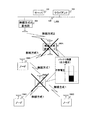
図23は、本発明の第2の実施の形態の測位方法2における送信出力制御の説明図である。   FIG. 23 is an explanatory diagram of transmission output control in the positioning method 2 according to the second embodiment of this invention.

本説明図では、サーバ101が、ノード108Aを測位する。   In this explanatory diagram, the server 101 positions the node 108A.

ノード108Aは、送信出力レベルを変えながら、同期信号及び観測信号を送信する。ここでは、ノード108Aは、低出力レベル又は高出力レベルのいずれかの送信出力レベルで、同期信号及び観測信号を送信する。   The node 108A transmits the synchronization signal and the observation signal while changing the transmission output level. Here, the node 108A transmits the synchronization signal and the observation signal at a transmission output level of either a low output level or a high output level.

例えば、ノード108Aが、低出力レベルで同期信号及び観測信号を送信する。すると、低出力レベルの動作範囲内に存在するノード108B、108C、108D及び108Eが、同期信号及び観測信号をノード108Aから受信する。なお、低出力レベルの動作範囲は、ノード108Aが低出力レベルで送信した同期信号及び観測信号を受信できる範囲である。   For example, the node 108A transmits the synchronization signal and the observation signal at a low output level. Then, the nodes 108B, 108C, 108D, and 108E existing within the operation range of the low output level receive the synchronization signal and the observation signal from the node 108A. The operation range of the low output level is a range in which the synchronization signal and the observation signal transmitted by the node 108A at the low output level can be received.

また、ノード108Aが、高出力レベルで同期信号及び観測信号を送信する。すると、高出力レベルの動作範囲内に存在するノード108B、108C、108D、108E、108F、108G、108H及び108Iが、同期信号及び観測信号をノード108Aから受信する。なお、高出力レベルの動作範囲は、ノード108Aが高出力レベルで送信した同期信号及び観測信号を受信できる範囲である。   Further, the node 108A transmits the synchronization signal and the observation signal at a high output level. Then, the nodes 108B, 108C, 108D, 108E, 108F, 108G, 108H, and 108I existing within the high output level operating range receive the synchronization signal and the observation signal from the node 108A. Note that the operation range of the high output level is a range in which the synchronization signal and the observation signal transmitted by the node 108A at the high output level can be received.

つまり、ノード108Aは、近くのノード108B、108C及び108Dに対しては、低い送信出力レベルで同期信号及び観測信号を送信する。また、ノード108Aは、遠くのノード108E、108F、108G及び108Hに対しては、高い送信出力レベルで同期信号及び観測信号を送信する。   That is, the node 108A transmits the synchronization signal and the observation signal to the nearby nodes 108B, 108C, and 108D at a low transmission output level. Further, the node 108A transmits the synchronization signal and the observation signal to the distant nodes 108E, 108F, 108G, and 108H at a high transmission output level.

ノード108Aが高出力レベルで同期信号及び観測信号を送信すると、当該同期信号及び観測信号を受信する周辺のノード108B等の数が多くなる。よって、サーバ101は、多くの周辺ノード108B等から測定情報を受信するので、ノード108Aの位置を高精度で算出できる。しかし、ノード108A等は、高出力レベルで同期信号及び観測信号を送信するので、消費電力が大きいという問題がある。   When the node 108A transmits a synchronization signal and an observation signal at a high output level, the number of peripheral nodes 108B and the like that receive the synchronization signal and the observation signal increases. Therefore, since the server 101 receives measurement information from many peripheral nodes 108B and the like, the position of the node 108A can be calculated with high accuracy. However, since the node 108A and the like transmit the synchronization signal and the observation signal at a high output level, there is a problem that the power consumption is large.

そこで、ノード108Aは、低出力レベルで同期信号及び観測信号を送信する。すると、サーバ101が算出するノード108Aの位置の精度は落ちるが、ノード108Aの消費電力を小さくできる。   Therefore, the node 108A transmits the synchronization signal and the observation signal at a low output level. Then, although the accuracy of the position of the node 108A calculated by the server 101 is lowered, the power consumption of the node 108A can be reduced.

図24は、本発明の第2の実施の形態の測位方法2における送信出力制御のシーケンス図である。   FIG. 24 is a sequence diagram of transmission output control in the positioning method 2 according to the second embodiment of this invention.

まず、サーバ101は、無線方式2の基地局201A等及び無線方式変換ノード202A等を介して、測位対象のノード108Aに測位指示を送信する。   First, the server 101 transmits a positioning instruction to the positioning target node 108A via the wireless system 2 base station 201A and the wireless system conversion node 202A and the like.

ノード108Aは、測位指示を受信すると、高出力レベルで同期信号及び観測信号を送信する。   When the node 108A receives the positioning instruction, the node 108A transmits the synchronization signal and the observation signal at a high output level.

すると、高出力レベルの動作範囲内に存在するノード108B、108C、108D、108E、108F、108G、108H及び108Iが、同期信号及び観測信号をノード108Aから受信する。このとき、高出力レベルの動作範囲内に存在するノード108B等は、受信した同期信号の受信電力を測定する。更に、同期信号の受信時刻及び観測信号の受信時刻を調べ、記憶する。   Then, the nodes 108B, 108C, 108D, 108E, 108F, 108G, 108H, and 108I existing within the high output level operating range receive the synchronization signal and the observation signal from the node 108A. At this time, the node 108B or the like existing in the high output level operating range measures the received power of the received synchronization signal. Further, the reception time of the synchronization signal and the reception time of the observation signal are checked and stored.

次に、高出力レベルの動作範囲内に存在するノード108B等は、記憶している観測信号の受信時刻から同期信号の受信時刻を減算することによって、同期信号と観測信号との時間差を求める。そして、求めた同期信号と観測信号との時間差を測定情報とする。   Next, the node 108B or the like existing within the operating range of the high output level obtains the time difference between the synchronization signal and the observation signal by subtracting the reception time of the synchronization signal from the stored reception time of the observation signal. Then, the obtained time difference between the synchronization signal and the observation signal is used as measurement information.

次に、求めた測定情報及び測定した受信電力情報をサーバ101に送信する。   Next, the obtained measurement information and the measured received power information are transmitted to the server 101.

サーバ101は、高出力レベルの動作範囲内に存在するノード108B等から、測定情報及び受信電力情報を受信する。そして、受信した測定情報に基づいて、ノード108Aの位置を算出する(2001)。   The server 101 receives measurement information and received power information from the node 108B or the like existing within the high power level operation range. Based on the received measurement information, the position of the node 108A is calculated (2001).

サーバ101及びノード108A等は、このような高出力レベル動作を所定の回数(例えば、N回)繰り返す。   The server 101, the node 108A, and the like repeat such a high output level operation a predetermined number of times (for example, N times).

次に、サーバ101は、受信した受信電力情報に基づいて、同期信号及び観測信号の送信出力レベルを決定する(2002)。   Next, the server 101 determines the transmission output level of the synchronization signal and the observation signal based on the received reception power information (2002).

具体的には、サーバ101は、ノード108Aの測位に最低限必要なノード108B等を特定する。そして、特定したノード108B等の中から、同期信号の受信電力が最も小さいノード108B等を選択する。次に、サーバ101は、測位対象のノード108Aの同期信号の送信電力から、選択したノード108Bの同期信号の受信電力を減算する。これによって、サーバ101は、同期信号の受信電力が最も小さいノード108Bと測位対象のノード108Aとの伝播損を求める。なお、サーバ101は、ノード108Aの同期信号の送信電力を予め記憶していてもよいし、ノード108Aから通知されてもよい。   Specifically, the server 101 specifies a node 108B and the like that are minimum required for positioning of the node 108A. Then, the node 108B or the like having the smallest received power of the synchronization signal is selected from the identified nodes 108B and the like. Next, the server 101 subtracts the received power of the synchronization signal of the selected node 108B from the transmission power of the synchronization signal of the positioning target node 108A. As a result, the server 101 obtains a propagation loss between the node 108B having the smallest received power of the synchronization signal and the node 108A for positioning. Note that the server 101 may store the transmission power of the synchronization signal of the node 108A in advance, or may be notified from the node 108A.

次に、サーバ101は、図22で説明したように、ノード108A等間の伝播損に基づいて、同期信号及び観測信号の送信出力レベルを決定する。   Next, as described with reference to FIG. 22, the server 101 determines the transmission output levels of the synchronization signal and the observation signal based on the propagation loss between the nodes 108A and the like.

そして、サーバ101は、決定した送信出力レベルをノード108Aに通知する。   Then, the server 101 notifies the determined transmission output level to the node 108A.

ノード108Aは、送信出力レベルの通知を受けると、通知された送信出力レベルで同期信号及び観測信号を送信する。ここでは、ノード108Aは、低出力レベルで同期信号及び観測信号を送信する。   Upon receiving the notification of the transmission output level, the node 108A transmits the synchronization signal and the observation signal at the notified transmission output level. Here, the node 108A transmits the synchronization signal and the observation signal at a low output level.

すると、低出力レベルの動作範囲内に存在するノード108B、108C、108D及び108Eが、同期信号及び観測信号をノード108Aから受信する。このとき、低出力レベルの動作範囲内に存在するノード108B等は、低出力レベルの動作範囲内に存在するノード108B等は、同期信号の受信時刻及び観測信号の受信時刻を調べ、記憶する。   Then, the nodes 108B, 108C, 108D, and 108E existing within the operation range of the low output level receive the synchronization signal and the observation signal from the node 108A. At this time, the node 108B and the like existing in the low output level operation range check and store the reception time of the synchronization signal and the observation signal of the node 108B and the like existing in the low output level operation range.

次に、低出力レベルの動作範囲内に存在するノード108B等は、記憶している観測信号の受信時刻から同期信号の受信時刻を減算することによって、同期信号と観測信号との時間差を求める。そして、求めた同期信号と観測信号との時間差を測定情報とし、サーバ101に送信する。   Next, the node 108B or the like existing in the operation range of the low output level obtains a time difference between the synchronization signal and the observation signal by subtracting the reception time of the synchronization signal from the stored reception time of the observation signal. Then, the obtained time difference between the synchronization signal and the observation signal is used as measurement information and transmitted to the server 101.

サーバ101は、低出力レベルの動作範囲内に存在するノード108B等から、測定情報を受信する。そして、受信した測定情報に基づいて、ノード108Aの位置を算出する(2001)。なお、サーバ101は、高出力レベル動作時にノード108F、108G、108H及び108Iから受信した測定情報も用いて、ノード108Aの位置を算出してもよい。   The server 101 receives measurement information from the node 108B or the like existing in the operation range of the low output level. Based on the received measurement information, the position of the node 108A is calculated (2001). Note that the server 101 may calculate the position of the node 108A using also the measurement information received from the nodes 108F, 108G, 108H, and 108I during the high power level operation.

サーバ101及びノード108A等は、このような低出力レベル動作を所定の回数(例えば、M回)繰り返す。   The server 101, the node 108A, and the like repeat such a low output level operation a predetermined number of times (for example, M times).

以上のように、サーバ101は、測位方法2においてノード108等の送信出力を制御しながら、ノード108Aを測位できる。   As described above, the server 101 can position the node 108A while controlling the transmission output of the node 108 and the like in the positioning method 2.

図25は、本発明の第2の実施の形態の測位方法3における送信出力制御の説明図である。   FIG. 25 is an explanatory diagram of transmission output control in the positioning method 3 according to the second embodiment of this invention.

本説明図では、サーバ101が、ノード108Aを測位する。   In this explanatory diagram, the server 101 positions the node 108A.

ノード108Aの周囲に存在するノード108B、108C、108D、108E、108F、108G、108H及び108Iは、それぞれ異なる送信出力レベルで同期信号及び観測信号を送信する。   The nodes 108B, 108C, 108D, 108E, 108F, 108G, 108H and 108I existing around the node 108A transmit the synchronization signal and the observation signal at different transmission output levels.

例えば、高出力レベル動作時において、高出力レベルの動作範囲内に存在するノード108B、108C、108D、108E、108F、108G、108H及び108Iは、高出力レベルで同期信号及び観測信号を送信する。   For example, at the time of high output level operation, the nodes 108B, 108C, 108D, 108E, 108F, 108G, 108H, and 108I existing in the high output level operation range transmit the synchronization signal and the observation signal at the high output level.

また、低出力レベル動作時において、低出力レベルの動作範囲内に存在するノード108B、108C、108D及び108Eは、低出力レベルで同期信号及び観測信号を送信する。   Further, during the low output level operation, the nodes 108B, 108C, 108D, and 108E existing in the operation range of the low output level transmit the synchronization signal and the observation signal at the low output level.

図26は、本発明の第2の実施の形態の測位方法3における送信出力制御のシーケンス図である。   FIG. 26 is a sequence diagram of transmission output control in the positioning method 3 according to the second embodiment of this invention.

まず、サーバ101は、無線方式2の基地局201A等及び無線方式変換ノード202A等を介して、高出力レベルの動作範囲内に存在するノード108B、108C、108D、108E、108F、108G、108H及び108Iに測位指示を送信する。   First, the server 101 receives the nodes 108B, 108C, 108D, 108E, 108F, 108G, 108H, and the like that exist within the high power level operation range via the wireless system 2 base station 201A and the wireless system conversion node 202A. A positioning instruction is transmitted to 108I.

すると、高出力レベルの動作範囲内に存在するノード108B等は、測位指示に含まれる送信タイミングで、同期信号及び観測信号を送信する。   Then, the node 108B and the like existing within the operation range of the high output level transmit the synchronization signal and the observation signal at the transmission timing included in the positioning instruction.

ノード108Aは、高出力レベルの動作範囲内に存在するノード108B等から、同期信号及び観測信号を受信する。このとき、ノード108Aは、受信した同期信号の受信電力を測定する。なお、ノード108Aは、高出力レベルの動作範囲内に存在するすべてのノード108B等の同期信号の受信電力を測定する。更に、ノード108Aは、同期信号の受信時刻及び観測信号の受信時刻を調べ、記憶する。   The node 108A receives the synchronization signal and the observation signal from the node 108B and the like existing in the high output level operation range. At this time, the node 108A measures the received power of the received synchronization signal. Note that the node 108 </ b> A measures the reception power of the synchronization signal of all the nodes 108 </ b> B and the like existing within the high output level operation range. Further, the node 108A checks and stores the reception time of the synchronization signal and the reception time of the observation signal.

次に、ノード108Aは、記憶している観測信号の受信時刻から同期信号の受信時刻を減算することによって、同期信号と観測信号との時間差を求める。なお、ノード108Aは、高出力レベルの動作範囲内に存在するすべてのノード108B等に対して、時間差を求める。そして、求めた同期信号と観測信号との時間差を測定情報とする。   Next, the node 108A obtains a time difference between the synchronization signal and the observation signal by subtracting the reception time of the synchronization signal from the stored reception time of the observation signal. Note that the node 108A obtains a time difference with respect to all the nodes 108B and the like existing in the operation range of the high output level. Then, the obtained time difference between the synchronization signal and the observation signal is used as measurement information.

次に、ノード108Aは、求めた測定情報及び測定した受信電力情報をサーバ101に送信する。   Next, the node 108 </ b> A transmits the obtained measurement information and the measured received power information to the server 101.

サーバ101は、ノード108A等から、測定情報及び受信電力情報を受信する。そして、受信した測定情報に基づいて、ノード108Aの位置を算出する(2201)。   The server 101 receives measurement information and received power information from the node 108A and the like. Based on the received measurement information, the position of the node 108A is calculated (2201).

サーバ101及びノード108A等は、このような高出力レベル動作を所定の回数(例えば、N回)繰り返す。   The server 101, the node 108A, and the like repeat such a high output level operation a predetermined number of times (for example, N times).

次に、サーバ101は、受信した受信電力情報に基づいて、同期信号及び観測信号の送信出力レベルを決定する(2202)。   Next, the server 101 determines the transmission output level of the synchronization signal and the observation signal based on the received reception power information (2202).

具体的には、サーバ101は、測位対象のノード108Aの測位に最低限必要なノード108B等を特定する。そして、特定したノード108B等の中から、ノード108Aが受信した受信電力が最も小さい同期信号を送信したノード108B等を選択する。次に、サーバ101は、選択したノード108B等の同期信号の送信電力から、選択したノード108Bの同期信号の受信電力を減算する。これによって、サーバ101は、選択したノード108B等と測位対象のノード108Aとの伝播損を求める。なお、サーバ101は、ノード108B等の同期信号の送信電力を予め記憶していてもよいし、ノード108B等から通知されてもよい。   Specifically, the server 101 specifies the minimum node 108B and the like necessary for positioning of the positioning target node 108A. Then, the node 108B or the like that has transmitted the synchronization signal with the smallest received power received by the node 108A is selected from the identified nodes 108B and the like. Next, the server 101 subtracts the received power of the synchronization signal of the selected node 108B from the transmission power of the synchronization signal of the selected node 108B or the like. As a result, the server 101 obtains a propagation loss between the selected node 108B and the like and the positioning target node 108A. The server 101 may store the transmission power of the synchronization signal of the node 108B or the like in advance, or may be notified from the node 108B or the like.

そして、サーバ101は、決定した送信出力レベルを、低出力レベルの動作範囲内に存在するノード108B、108C、108D及び108Eに通知する。   Then, the server 101 notifies the determined transmission output level to the nodes 108B, 108C, 108D, and 108E existing in the operation range of the low output level.

低出力レベルの動作範囲内に存在するノード108B等は、送信出力レベルの通知を受けると、通知された送信出力レベルで同期信号及び観測信号を送信する。ここでは、低出力レベルの動作範囲内に存在するノード108B等は、低出力レベルで同期信号及び観測信号を送信する。   Upon receiving the notification of the transmission output level, the node 108B and the like existing within the operation range of the low output level transmits the synchronization signal and the observation signal at the notified transmission output level. Here, the node 108B and the like existing within the operation range of the low output level transmit the synchronization signal and the observation signal at the low output level.

ノード108Aは、低出力レベルの動作範囲内に存在するノード108B等から、同期信号及び観測信号を受信する。このとき、ノード108Aは、同期信号の受信時刻及び観測信号の受信時刻を調べ、記憶する。次に、ノード108Aは、記憶している観測信号の受信時刻から同期信号の受信時刻を減算することによって、同期信号と観測信号との時間差を求める。なお、ノード108Aは、低出力レベルの動作範囲内に存在するすべてのノード108B等に対して、時間差を求める。そして、求めた同期信号と観測信号との時間差を測定情報とする。   The node 108A receives the synchronization signal and the observation signal from the node 108B and the like existing in the operation range of the low output level. At this time, the node 108A checks and stores the reception time of the synchronization signal and the reception time of the observation signal. Next, the node 108A obtains a time difference between the synchronization signal and the observation signal by subtracting the reception time of the synchronization signal from the stored reception time of the observation signal. Note that the node 108A calculates a time difference with respect to all the nodes 108B and the like existing in the operation range of the low output level. Then, the obtained time difference between the synchronization signal and the observation signal is used as measurement information.

次に、ノード108Aは、求めた測定情報をサーバ101に送信する。   Next, the node 108A transmits the obtained measurement information to the server 101.

サーバ101は、ノード108A等から、測定情報を受信する。そして、受信した測定情報に基づいて、ノード108Aの位置を算出する(2203)。なお、サーバ101は、高出力レベル動作時にノード108F、108G、108H及び108Iから受信した測定情報も用いて、ノード108Aの位置を算出してもよい。   The server 101 receives measurement information from the node 108A or the like. Based on the received measurement information, the position of the node 108A is calculated (2203). Note that the server 101 may calculate the position of the node 108A using also the measurement information received from the nodes 108F, 108G, 108H, and 108I during the high power level operation.

サーバ101及びノード108A等は、このような低出力レベル動作を所定の回数(例えば、M回)繰り返す。   The server 101, the node 108A, and the like repeat such a low output level operation a predetermined number of times (for example, M times).

以上のように、サーバ101は、測位方法3においてノード108等の送信出力を制御しながら、ノード108Aを測位できる。   As described above, the server 101 can position the node 108A while controlling the transmission output of the node 108 and the like in the positioning method 3.

本実施の形態では、測位方法2及び測位方法3における送信出力制御を説明した。同様に、測位方法1、測位方法4及び測位方法5においても、サーバ101は、ノード108A等の送信出力を制御できる。   In the present embodiment, transmission output control in the positioning method 2 and the positioning method 3 has been described. Similarly, also in the positioning method 1, the positioning method 4, and the positioning method 5, the server 101 can control the transmission output of the node 108A and the like.

第2の実施の形態によれば、ノード108A等は、消費電力を更に低減できる。   According to the second embodiment, the node 108A and the like can further reduce power consumption.

本発明は、ノードの位置を算出する無線通信システムに適用できる。   The present invention can be applied to a wireless communication system that calculates the position of a node.

本発明の第1の実施の形態の単一の無線方式で通信する位置検出システムのブロック図である。It is a block diagram of the position detection system which communicates by the single radio | wireless system of the 1st Embodiment of this invention. 本発明の第1の実施の形態の複数の無線方式で通信する位置検出システムのブロック図である。It is a block diagram of the position detection system which communicates with the some radio | wireless system of the 1st Embodiment of this invention. 本発明の第1の実施の形態のノードのブロック図である。It is a block diagram of the node of the 1st Embodiment of this invention. 本発明の第1の実施の形態の無線方式変換ノードのブロック図である。It is a block diagram of the radio | wireless system conversion node of the 1st Embodiment of this invention. 本発明の第1の実施の形態の無線方式2の基地局のブロック図である。It is a block diagram of the base station of the radio | wireless system 2 of the 1st Embodiment of this invention. 本発明の第1の実施の形態のサーバのブロック図である。It is a block diagram of a server of a 1st embodiment of the present invention. 本発明の第1の実施の形態の位置算出方法1の説明図である。It is explanatory drawing of the position calculation method 1 of the 1st Embodiment of this invention. 本発明の第1の実施の形態の位置算出方法1の説明図である。It is explanatory drawing of the position calculation method 1 of the 1st Embodiment of this invention. 本発明の第1の実施の形態の位置算出方法2の説明図である。It is explanatory drawing of the position calculation method 2 of the 1st Embodiment of this invention. 本発明の第1の実施の形態の位置算出方法2の説明図である。It is explanatory drawing of the position calculation method 2 of the 1st Embodiment of this invention. 本発明の実施の形態のサーバのノード位置算出処理のフローチャートである。It is a flowchart of the node position calculation process of the server of embodiment of this invention. 本発明の第1の実施の形態のサーバのノード位置算出処理の問題点の説明図である。It is explanatory drawing of the problem of the node position calculation process of the server of the 1st Embodiment of this invention. 本発明の第1の実施の形態の測位方法1の説明図である。It is explanatory drawing of the positioning method 1 of the 1st Embodiment of this invention. 本発明の第1の実施の形態の測位方法1のシーケンス図である。It is a sequence diagram of the positioning method 1 of the 1st Embodiment of this invention. 本発明の第1の実施の形態の測位方法2の説明図である。It is explanatory drawing of the positioning method 2 of the 1st Embodiment of this invention. 本発明の第1の実施の形態の測位方法2のシーケンス図である。It is a sequence diagram of the positioning method 2 of the 1st Embodiment of this invention. 本発明の第1の実施の形態の測位方法3の説明図である。It is explanatory drawing of the positioning method 3 of the 1st Embodiment of this invention. 本発明の第1の実施の形態の測位方法3のシーケンス図である。It is a sequence diagram of the positioning method 3 of the 1st Embodiment of this invention. 本発明の第1の実施の形態の測位方法4の説明図である。It is explanatory drawing of the positioning method 4 of the 1st Embodiment of this invention. 本発明の第1の実施の形態の測位方法4のシーケンス図である。It is a sequence diagram of the positioning method 4 of the 1st Embodiment of this invention. 本発明の第1の実施の形態の測位方法5の説明図である。It is explanatory drawing of the positioning method 5 of the 1st Embodiment of this invention. 本発明の第1の実施の形態の測位方法5のシーケンス図である。It is a sequence diagram of the positioning method 5 of the 1st Embodiment of this invention. 本発明の第1の実施の形態の無線方式変換ノードの消費電力のグラフである。It is a graph of the power consumption of the radio | wireless system conversion node of the 1st Embodiment of this invention. 本発明の第1の実施の形態の位置検出システムの位置算出処理のシーケンス図である。It is a sequence diagram of the position calculation process of the position detection system of the 1st Embodiment of this invention. 本発明の第1の実施の形態にサーバが備えるシステム管理ポリシーの説明図である。It is explanatory drawing of the system management policy with which a server is provided in the 1st Embodiment of this invention. 本発明の第1の実施の形態の無線方式変換ノード状態管理データの実測状態テーブルの構成図である。It is a block diagram of the measurement state table of the radio | wireless system conversion node state management data of the 1st Embodiment of this invention. 本発明の第1の実施の形態の無線方式変換ノード状態管理データの測位手法選択テーブルの構成図である。It is a block diagram of the positioning method selection table of the radio | wireless system conversion node state management data of the 1st Embodiment of this invention. 本発明の第1の実施の形態の無線方式変換ノード状態管理データの予測リストテーブルの構成図である。It is a block diagram of the prediction list table of the radio | wireless system conversion node state management data of the 1st Embodiment of this invention. 本発明の第1の実施の形態のノード状態管理データの実測状態テーブルの構成図である。It is a block diagram of the measurement state table of the node state management data according to the first embodiment of this invention. 本発明の第1の実施の形態のノード状態管理データの測位手法選択テーブルの構成図である。It is a block diagram of the positioning method selection table of the node state management data according to the first embodiment of this invention. 本発明の第1の実施の形態のノード状態管理データの予測リストテーブルの構成図である。FIG. 3 is a configuration diagram of a prediction list table of node state management data according to the first embodiment of this invention. 本発明の第1の実施の形態におけるサーバの測位手法決定処理のフローチャートである。It is a flowchart of the positioning method determination process of the server in the 1st Embodiment of this invention. 本発明の第2の実施の形態のノードの送信出力制御の説明図である。It is explanatory drawing of the transmission output control of the node of the 2nd Embodiment of this invention. 本発明の第2の実施の形態の測位方法2における送信出力制御の説明図である。It is explanatory drawing of the transmission output control in the positioning method 2 of the 2nd Embodiment of this invention. 本発明の第2の実施の形態の測位方法2における送信出力制御のシーケンス図である。It is a sequence diagram of transmission output control in the positioning method 2 of the 2nd Embodiment of this invention. 本発明の第2の実施の形態の測位方法3における送信出力制御の説明図である。It is explanatory drawing of the transmission output control in the positioning method 3 of the 2nd Embodiment of this invention. 本発明の第2の実施の形態の測位方法3における送信出力制御のシーケンス図である。It is a sequence diagram of transmission output control in the positioning method 3 of the 2nd Embodiment of this invention.

符号の説明Explanation of symbols

101 サーバ
102 ノード位置情報データ
103 センサデータ
104 クライアント
105 センサデータ利用アプリケーション
106 LAN
107 無線方式1の基地局
108A、108B、108C、108D、108E、108F、108G、108H、108I ノード
201A、201B、201C 無線方式2の基地局
202A、202B、202C 無線方式変換ノード
1001 同期信号基準局
1401 位置計算処理部
1402 無線方式変換ノード位置情報データ
1403 システム管理ポリシー
1404 ノード状態管理データ
1405 無線方式変換ノード状態管理データ
1406 制御部
1501 要求測位精度マップ
1502 要求測位時間マップ
1801 送信出力テーブル
2301 アンテナ
2302 無線方式1の送信部
2303 無線方式1の受信部
2304 受信電力測定部
2305 制御部
2306 バッテリ状態測定部
2307 バッテリ
2308 センサ情報測定部
2309 センサ
2310 送信出力制御部
2311 観測信号送信部
2312 観測信号受信部
2401 アンテナ
2402 切替スイッチ
2403 無線方式1の送信部
2404 無線方式1の受信部
2405 受信電力測定部
2406 無線方式2の送信部
2407 無線方式2の受信部
2408 制御部
2409 バッテリ状態測定部
2410 バッテリ
2411 送信出力制御部
2412 観測信号送信部
2413 観測信号受信部
2501 アンテナ
2502 無線方式2の送信部
2503 無線方式2の受信部
2504 受信電力測定部
2505 制御部
2506 電源回路
2507 有線送信部
2508 有線受信部
2509 送信出力制御部
2510 観測信号送信部
2511 観測信号受信部
101 Server 102 Node position information data 103 Sensor data 104 Client 105 Sensor data utilization application 106 LAN
107 base station 108A, 108B, 108C, 108D, 108E, 108F, 108G, 108H, 108I node 201A, 201B, 201C base station 202A, 202B, 202C of radio system 2 radio system conversion node 1001 synchronization signal reference station 1401 Position calculation processing unit 1402 Wireless system conversion node position information data 1403 System management policy 1404 Node state management data 1405 Wireless system conversion node state management data 1406 Control unit 1501 Requested positioning accuracy map 1502 Requested positioning time map 1801 Transmission output table 2301 Antenna 2302 Wireless Transmission unit 2303 of system 1 Reception unit 2304 of wireless system 1 Received power measurement unit 2305 Control unit 2306 Battery state measurement unit 2307 Battery 2308 Sensor information measurement unit 2 309 sensor 2310 transmission output control unit 2311 observation signal transmission unit 2312 observation signal reception unit 2401 antenna 2402 changeover switch 2403 wireless system 1 transmission unit 2404 wireless system 1 reception unit 2405 reception power measurement unit 2406 wireless system 2 transmission unit 2407 wireless System 2 reception unit 2408 Control unit 2409 Battery state measurement unit 2410 Battery 2411 Transmission output control unit 2412 Observation signal transmission unit 2413 Observation signal reception unit 2501 Antenna 2502 Radio system 2 transmission unit 2503 Radio system 2 reception unit 2504 Reception power measurement Unit 2505 control unit 2506 power supply circuit 2507 wired transmission unit 2508 wired reception unit 2509 transmission output control unit 2510 observation signal transmission unit 2511 observation signal reception unit

Claims (10)

互いに通信する複数のノードと、前記ノード間の通信を用いて前記ノードを測位するサーバと、を備える無線通信システムにおいて、
前記ノードは、
電力を供給するバッテリを有し、
前記バッテリの状態を測定し、
前記ノード間での時刻の同期に用いられる同期信号を受信すると、当該同期信号の受信電力を測定し、
前記測定したバッテリの状態及び前記同期信号の受信電力をサーバに通知し、
前記サーバは、
前記ノードから通知された受信電力に基づいて、前記ノード間の距離の測定に用いられる観測信号の送信出力を決定し、
前記決定した送信出力を前記ノードに通知し、
前記ノードから通知されたバッテリの状態に基づいて、当該ノードの測位方法を決定し、
前記決定した測位方法によって、当該ノードの位置を算出することを特徴とする無線通信システム。
In a wireless communication system comprising a plurality of nodes that communicate with each other, and a server that positions the nodes using communication between the nodes,
The node is
Having a battery to supply power,
Measuring the state of the battery;
Upon receiving a synchronization signal used for time synchronization between the nodes, measure the received power of the synchronization signal,
Notifying the server of the measured battery status and the received power of the synchronization signal ,
The server
Based on the received power notified from the node, determine the transmission power of the observation signal used for measuring the distance between the nodes,
Notifying the node of the determined transmission output,
Based on the state of the battery notified from the node, determine the positioning method of the node,
A wireless communication system, wherein the position of the node is calculated by the determined positioning method.
前記サーバが決定しうる測位方法は、
測位対象の前記ノードが、前記ノード間での時刻の同期に用いられる同期信号及び前記ノード間の距離の測定に用いられる観測信号を送信し、
測位対象でない前記ノードが、
同期信号及び観測信号を前記測位対象のノードから受信し、
前記サーバが、前記測位対象でないノードが前記同期信号を受信した時刻と当該ノードが前記観測信号を受信した時刻との差に基づいて、前記ノードの位置を算出することを特徴とする請求項1に記載の無線通信システム。
The positioning method that can be determined by the server is:
The node to be measured transmits a synchronization signal used for time synchronization between the nodes and an observation signal used for measuring a distance between the nodes,
The node that is not a positioning target is
Receiving a synchronization signal and an observation signal from the positioning target node;
2. The server calculates the position of the node based on a difference between a time when the node that is not a positioning target receives the synchronization signal and a time when the node receives the observation signal. The wireless communication system according to 1.
前記ノード間での時刻の同期に用いられる同期信号を送信する同期信号基準局を備え、
前記サーバが決定しうる測位方法は、
測位対象の前記ノードが、前記ノード間の距離の測定に用いられる観測信号を送信し、
前記同期信号基準局は、前記観測信号を前記測位対象のノードから受信すると、前記同期信号を送信し、
測位対象でない前記ノードが、
前記観測信号を前記測位対象のノードから受信し、
前記同期信号を前記同期信号基準局から受信し、
前記サーバが、前記測位対象でないノードが前記同期信号を受信した時刻と当該ノードが前記観測信号を受信した時刻との差に基づいて、前記ノードの位置を算出することを特徴とする請求項1に記載の無線通信システム。
A synchronization signal reference station for transmitting a synchronization signal used for time synchronization between the nodes;
The positioning method that can be determined by the server is:
The node to be measured transmits an observation signal used for measuring a distance between the nodes,
When the synchronization signal reference station receives the observation signal from the positioning target node, it transmits the synchronization signal,
The node that is not a positioning target is
Receiving the observation signal from the positioning target node;
Receiving the synchronization signal from the synchronization signal reference station;
2. The server calculates the position of the node based on a difference between a time when the node that is not a positioning target receives the synchronization signal and a time when the node receives the observation signal. The wireless communication system according to 1.
前記サーバは、
前記ノードから通知されたバッテリの状態及び前記ノードのバッテリの消費量に基づいて、バッテリの交換時期を測位方法ごとに推定し、
推定したバッテリの交換時期に基づいて、前記ノードの測位方法を決定することを特徴とする請求項1に記載の無線通信システム。
The server
Based on the state of the battery notified from the node and the battery consumption of the node, estimate the battery replacement time for each positioning method,
The wireless communication system according to claim 1, wherein a positioning method of the node is determined based on the estimated battery replacement time.
前記ノードは、前記サーバからの通知に基づいて、観測信号の送信出力を制御することを特徴とする請求項1に記載の無線通信システム。The wireless communication system according to claim 1, wherein the node controls the transmission output of the observation signal based on a notification from the server. 前記ノードは、バッテリの消費量が異なる複数の通信部を有することを特徴とする請求項1に記載の無線通信システム。The wireless communication system according to claim 1, wherein the node includes a plurality of communication units having different battery consumption amounts. 複数のノード間の通信を用いて前記ノードを測位するサーバにおけるノード位置算出方法であって、A node position calculation method in a server for positioning the node using communication between a plurality of nodes,
前記ノードのバッテリの状態、及び、前記ノードが他の前記ノードから受信した、前記ノード間での時刻の同期に用いられる同期信号の受信電力を取得し、  Obtaining the received power of the synchronization signal used for synchronizing the time between the nodes, the state of the battery of the node, and the node received from the other node;
前記取得した受信電力に基づいて、前記ノード間の距離の測定に用いられる観測信号の送信出力を決定し、  Based on the acquired received power, determine the transmission power of the observation signal used to measure the distance between the nodes,
前記決定した送信出力を前記ノードに通知し、  Notifying the node of the determined transmission output,
前記取得したバッテリの状態に基づいて、当該ノードの測位方法を決定し、  Based on the obtained battery state, determine a positioning method of the node,
前記決定した測位方法によって、当該ノードの位置を算出することを特徴とするノード位置算出方法。  A node position calculation method, wherein the position of the node is calculated by the determined positioning method.
互いに通信する複数のノードと、前記ノード間の通信を用いて前記ノードを測位するサーバと、を備える無線通信システムにおけるノードであって、A node in a wireless communication system comprising a plurality of nodes communicating with each other and a server for positioning the node using communication between the nodes,
電力を供給するバッテリを有し、  Having a battery to supply power,
前記バッテリの状態を測定し、  Measuring the state of the battery;
前記ノード間での時刻の同期に用いられる同期信号を受信すると、当該同期信号の受信電力を測定し、  Upon receiving a synchronization signal used for time synchronization between the nodes, measure the received power of the synchronization signal,
前記測定したバッテリの状態及び前記同期信号の受信電力をサーバに通知し、  Notifying the server of the measured battery status and the received power of the synchronization signal,
前記サーバから測位方法を通知されると、前記通知された測位方法に対応する処理を実行することを特徴とするノード。  A node that, when notified of a positioning method from the server, executes a process corresponding to the notified positioning method.
バッテリの消費量が異なる複数の通信部を有することを特徴とする請求項8に記載のノード。The node according to claim 8, comprising a plurality of communication units having different battery consumption amounts. 通知された受信電力に基づいて決定される前記ノード間の距離の測定に用いられる観測信号の送信出力を前記サーバから受信し、前記受信した送信出力に基づいて観測信号を制御することを特徴とする請求項8に記載のノード。Receiving the transmission output of the observation signal used for measuring the distance between the nodes determined based on the notified received power from the server, and controlling the observation signal based on the received transmission output, The node according to claim 8.
JP2005155194A 2005-05-27 2005-05-27 Wireless communication system, node position calculation method, and node Expired - Fee Related JP4568641B2 (en)

Priority Applications (2)

Application Number Priority Date Filing Date Title
JP2005155194A JP4568641B2 (en) 2005-05-27 2005-05-27 Wireless communication system, node position calculation method, and node
US11/287,403 US7474646B2 (en) 2005-05-27 2005-11-28 Wireless communication system, node position calculation method and node

Applications Claiming Priority (1)

Application Number Priority Date Filing Date Title
JP2005155194A JP4568641B2 (en) 2005-05-27 2005-05-27 Wireless communication system, node position calculation method, and node

Publications (3)

Publication Number Publication Date
JP2006329854A JP2006329854A (en) 2006-12-07
JP2006329854A5 JP2006329854A5 (en) 2008-01-31
JP4568641B2 true JP4568641B2 (en) 2010-10-27

Family

ID=37463245

Family Applications (1)

Application Number Title Priority Date Filing Date
JP2005155194A Expired - Fee Related JP4568641B2 (en) 2005-05-27 2005-05-27 Wireless communication system, node position calculation method, and node

Country Status (2)

Country Link
US (1) US7474646B2 (en)
JP (1) JP4568641B2 (en)

Families Citing this family (25)

* Cited by examiner, † Cited by third party
Publication number Priority date Publication date Assignee Title
JP4824993B2 (en) * 2005-11-16 2011-11-30 株式会社エヌ・ティ・ティ・ドコモ Positioning system and positioning method
US7835754B2 (en) 2006-05-08 2010-11-16 Skyhook Wireless, Inc. Estimation of speed and direction of travel in a WLAN positioning system
US7515578B2 (en) * 2006-05-08 2009-04-07 Skyhook Wireless, Inc. Estimation of position using WLAN access point radio propagation characteristics in a WLAN positioning system
US7551929B2 (en) * 2006-05-08 2009-06-23 Skyhook Wireless, Inc. Estimation of speed and direction of travel in a WLAN positioning system using multiple position estimations
US7551579B2 (en) * 2006-05-08 2009-06-23 Skyhook Wireless, Inc. Calculation of quality of wlan access point characterization for use in a wlan positioning system
US7856234B2 (en) 2006-11-07 2010-12-21 Skyhook Wireless, Inc. System and method for estimating positioning error within a WLAN-based positioning system
US8340699B2 (en) * 2006-12-19 2012-12-25 Sap Ag Method and system for monitoring high availability support system
WO2008135331A2 (en) * 2007-05-03 2008-11-13 Telefonaktiebolaget L M Ericsson (Publ) Method and system for trigger negotiation in supl
US8213954B2 (en) * 2007-08-28 2012-07-03 Motorola Solutions, Inc. Method for addressing user location errors in a cognitive radio system
US8803737B2 (en) * 2008-02-29 2014-08-12 Apple Inc. Location determination
US8213389B2 (en) * 2008-04-15 2012-07-03 Apple Inc. Location determination using formula
DE102008021701A1 (en) * 2008-04-28 2009-10-29 Fraunhofer-Gesellschaft zur Förderung der angewandten Forschung e.V. Method and device for localization of at least one object
US20100259444A1 (en) * 2009-04-08 2010-10-14 Andrei Kosolobov Method and system for dynamic wireless node capture for a lbs server, client, and reference database
WO2010122791A1 (en) * 2009-04-24 2010-10-28 パナソニック株式会社 Wireless ultrasonic diagnostic device, wireless ultrasonic probe, and probe certification method
JP5207400B2 (en) * 2009-07-13 2013-06-12 株式会社日立製作所 POSITION INFORMATION PROVIDING SYSTEM, POSITION INFORMATION PROVIDING METHOD, AND POSITIONING INTEGRATION DEVICE
US8874710B2 (en) * 2010-04-27 2014-10-28 Nokia Corporation Access network discovery
CN103140865A (en) * 2010-07-30 2013-06-05 Abb研究有限公司 A method and a system for localization in industrial wireless sensor network
ITTO20110284A1 (en) * 2011-03-29 2011-06-28 Sisvel Technology Srl COOPERATIVE LOCATION PROCEDURE AND ITS APPARATUSES
US8549010B2 (en) * 2011-05-13 2013-10-01 Nokia Corporation Method and apparatus for providing distributed key range management
US8787944B2 (en) * 2011-08-18 2014-07-22 Rivada Research, Llc Method and system for providing enhanced location based information for wireless handsets
GB2509350B (en) * 2011-10-13 2016-11-02 Omron Tateisi Electronics Co Network system, node device group and sensor device group
US8755331B2 (en) 2011-12-13 2014-06-17 International Business Machines Corporation Determining a physical location of a wireless mobile device
JP6241036B2 (en) * 2013-01-08 2017-12-06 株式会社リコー Communication terminal, position management system, and communication method
JP6510988B2 (en) * 2016-01-20 2019-05-08 日本電信電話株式会社 Positioning system and positioning method
JP6847782B2 (en) * 2017-07-07 2021-03-24 日本電信電話株式会社 Distance judgment system and distance judgment method

Citations (11)

* Cited by examiner, † Cited by third party
Publication number Priority date Publication date Assignee Title
JPH02102477A (en) * 1988-10-08 1990-04-16 Honda Motor Co Ltd Ultrasonic distance measuring instrument
WO2001061373A1 (en) * 2000-02-18 2001-08-23 Ericsson Inc. Handoff between external and internal positioning systems
JP2002267734A (en) * 2001-03-07 2002-09-18 Casio Comput Co Ltd Positioning device, method of setting positioning interval, and method of notifying operation period
JP2003032327A (en) * 2001-07-13 2003-01-31 Kyocera Corp Telephone terminal, communication controller, and method for calculating replacement period of battery
JP2003050272A (en) * 2001-08-06 2003-02-21 Mitsubishi Heavy Ind Ltd Position measuring system of moving body and control station for position measurement
JP2003518261A (en) * 1999-12-22 2003-06-03 イノベイティブ テクノロジー ライセンシング エルエルシー Position confirmation system for tracking with relay assist
JP2003207556A (en) * 2002-01-10 2003-07-25 Hitachi Ltd Terminal and server device in terminal position information system
JP2004040171A (en) * 2002-06-28 2004-02-05 Seiko Epson Corp Portable terminal and positioning method switching system for portable terminal
JP2004101254A (en) * 2002-09-06 2004-04-02 Hitachi Ltd Wireless system, its server, and its base station
JP2005086579A (en) * 2003-09-09 2005-03-31 Advanced Inst Of Wearable Environmental Information Networks System and method for detecting location of mobile object by short range radio communication
JP2005283236A (en) * 2004-03-29 2005-10-13 Seiko Epson Corp Positioning apparatus, control method for positioning apparatus, control program of positioning apparatus, and computer readable recording medium storing its control program

Family Cites Families (6)

* Cited by examiner, † Cited by third party
Publication number Priority date Publication date Assignee Title
US6314281B1 (en) * 1998-07-14 2001-11-06 Lucent Technologies Inc. Method and apparatus for precisely locating a mobile unit
US6751455B1 (en) * 1999-09-17 2004-06-15 The Regents Of The University Of California Power- and bandwidth-adaptive in-home wireless communications system with power-grid-powered agents and battery-powered clients
EP1496370A1 (en) * 2000-02-02 2005-01-12 Nokia Corporation Position Acquisition
US7006453B1 (en) * 2000-03-14 2006-02-28 Lucent Technologies Inc. Location based routing for mobile ad-hoc networks
US6735448B1 (en) * 2000-11-07 2004-05-11 Hrl Laboratories, Llc Power management for throughput enhancement in wireless ad-hoc networks
US6473038B2 (en) * 2001-01-05 2002-10-29 Motorola, Inc. Method and apparatus for location estimation

Patent Citations (11)

* Cited by examiner, † Cited by third party
Publication number Priority date Publication date Assignee Title
JPH02102477A (en) * 1988-10-08 1990-04-16 Honda Motor Co Ltd Ultrasonic distance measuring instrument
JP2003518261A (en) * 1999-12-22 2003-06-03 イノベイティブ テクノロジー ライセンシング エルエルシー Position confirmation system for tracking with relay assist
WO2001061373A1 (en) * 2000-02-18 2001-08-23 Ericsson Inc. Handoff between external and internal positioning systems
JP2002267734A (en) * 2001-03-07 2002-09-18 Casio Comput Co Ltd Positioning device, method of setting positioning interval, and method of notifying operation period
JP2003032327A (en) * 2001-07-13 2003-01-31 Kyocera Corp Telephone terminal, communication controller, and method for calculating replacement period of battery
JP2003050272A (en) * 2001-08-06 2003-02-21 Mitsubishi Heavy Ind Ltd Position measuring system of moving body and control station for position measurement
JP2003207556A (en) * 2002-01-10 2003-07-25 Hitachi Ltd Terminal and server device in terminal position information system
JP2004040171A (en) * 2002-06-28 2004-02-05 Seiko Epson Corp Portable terminal and positioning method switching system for portable terminal
JP2004101254A (en) * 2002-09-06 2004-04-02 Hitachi Ltd Wireless system, its server, and its base station
JP2005086579A (en) * 2003-09-09 2005-03-31 Advanced Inst Of Wearable Environmental Information Networks System and method for detecting location of mobile object by short range radio communication
JP2005283236A (en) * 2004-03-29 2005-10-13 Seiko Epson Corp Positioning apparatus, control method for positioning apparatus, control program of positioning apparatus, and computer readable recording medium storing its control program

Also Published As

Publication number Publication date
JP2006329854A (en) 2006-12-07
US20060268795A1 (en) 2006-11-30
US7474646B2 (en) 2009-01-06

Similar Documents

Publication Publication Date Title
JP4568641B2 (en) Wireless communication system, node position calculation method, and node
Čabarkapa et al. Comparative analysis of the bluetooth low-energy indoor positioning systems
EP1355283B1 (en) Positional information management system and method
CN107192980B (en) Adaptive passive scanning and/or active probing techniques for mobile device positioning
CN108370551B (en) Positioning method based on arrival time difference, user equipment and network equipment
EP2360973B1 (en) A method and system for location-based dynamic radio selection
JP6087556B2 (en) Wireless communication terminal, wireless communication device, wireless communication system, frequency band switching method
EP2567250B1 (en) Signal phase-based location of network nodes
JP2008167440A (en) Positioning method and apparatus in wireless multihop network
JP2006352810A (en) Radio control chip set with positioning function, radio communication card with positioning function, radio terminal, and position measuring network system
US10976403B2 (en) Position detection system and receiver
EP4014610B1 (en) Positioning
JP2016522403A (en) Method and apparatus for characterizing and influencing the accuracy and / or uncertainty of mobile device locations
KR20140040839A (en) Method and apparatus for geo-locating mobile station
TWI484206B (en) Spatial arrangement of a majority of communication devices and the method for determining the spatial location of a device
EP2507646B1 (en) Message-based location of mobile network nodes
JP5460587B2 (en) Method and configuration for location measurement in mobile communication networks
EP4147502A1 (en) User equipment, network node and methods in a radio communications network
JP2015102461A (en) Mobile terminal, device, control method, and program
JP5089626B2 (en) POSITION ESTIMATION METHOD, MOBILE TERMINAL AND PROGRAM USING EVALUATION VALUE FOR ESTIMATED POSITION
JP4584299B2 (en) Position management system, position management method, and management apparatus
WO2019086098A1 (en) Network access node and methods thereof
KR20120038296A (en) Posotioning system and method of mobile terminal
CN103826262A (en) Wireless communication system, wireless communication method, transmitting terminal, and receiving terminal
Kirci et al. Wireless sensor networks and efficient localisation

Legal Events

Date Code Title Description
A521 Written amendment

Free format text: JAPANESE INTERMEDIATE CODE: A523

Effective date: 20071205

A621 Written request for application examination

Free format text: JAPANESE INTERMEDIATE CODE: A621

Effective date: 20071205

A977 Report on retrieval

Free format text: JAPANESE INTERMEDIATE CODE: A971007

Effective date: 20100416

A131 Notification of reasons for refusal

Free format text: JAPANESE INTERMEDIATE CODE: A131

Effective date: 20100427

A521 Written amendment

Free format text: JAPANESE INTERMEDIATE CODE: A523

Effective date: 20100628

TRDD Decision of grant or rejection written
A01 Written decision to grant a patent or to grant a registration (utility model)

Free format text: JAPANESE INTERMEDIATE CODE: A01

Effective date: 20100713

A01 Written decision to grant a patent or to grant a registration (utility model)

Free format text: JAPANESE INTERMEDIATE CODE: A01

A61 First payment of annual fees (during grant procedure)

Free format text: JAPANESE INTERMEDIATE CODE: A61

Effective date: 20100809

R150 Certificate of patent or registration of utility model

Free format text: JAPANESE INTERMEDIATE CODE: R150

FPAY Renewal fee payment (event date is renewal date of database)

Free format text: PAYMENT UNTIL: 20130813

Year of fee payment: 3

LAPS Cancellation because of no payment of annual fees