EP1396326B1 - Connector between a fluid conduit and the opening of a resin container - Google Patents
Connector between a fluid conduit and the opening of a resin container Download PDFInfo
- Publication number
- EP1396326B1 EP1396326B1 EP20030011989 EP03011989A EP1396326B1 EP 1396326 B1 EP1396326 B1 EP 1396326B1 EP 20030011989 EP20030011989 EP 20030011989 EP 03011989 A EP03011989 A EP 03011989A EP 1396326 B1 EP1396326 B1 EP 1396326B1
- Authority
- EP
- European Patent Office
- Prior art keywords
- component
- structural member
- container
- annular groove
- tubular
- Prior art date
- Legal status (The legal status is an assumption and is not a legal conclusion. Google has not performed a legal analysis and makes no representation as to the accuracy of the status listed.)
- Expired - Lifetime
Links
Images


Classifications
-
- B—PERFORMING OPERATIONS; TRANSPORTING
- B60—VEHICLES IN GENERAL
- B60K—ARRANGEMENT OR MOUNTING OF PROPULSION UNITS OR OF TRANSMISSIONS IN VEHICLES; ARRANGEMENT OR MOUNTING OF PLURAL DIVERSE PRIME-MOVERS IN VEHICLES; AUXILIARY DRIVES FOR VEHICLES; INSTRUMENTATION OR DASHBOARDS FOR VEHICLES; ARRANGEMENTS IN CONNECTION WITH COOLING, AIR INTAKE, GAS EXHAUST OR FUEL SUPPLY OF PROPULSION UNITS IN VEHICLES
- B60K15/00—Arrangement in connection with fuel supply of combustion engines or other fuel consuming energy converters, e.g. fuel cells; Mounting or construction of fuel tanks
- B60K15/03—Fuel tanks
- B60K15/035—Fuel tanks characterised by venting means
- B60K15/03519—Valve arrangements in the vent line
-
- B—PERFORMING OPERATIONS; TRANSPORTING
- B29—WORKING OF PLASTICS; WORKING OF SUBSTANCES IN A PLASTIC STATE IN GENERAL
- B29C—SHAPING OR JOINING OF PLASTICS; SHAPING OF MATERIAL IN A PLASTIC STATE, NOT OTHERWISE PROVIDED FOR; AFTER-TREATMENT OF THE SHAPED PRODUCTS, e.g. REPAIRING
- B29C45/00—Injection moulding, i.e. forcing the required volume of moulding material through a nozzle into a closed mould; Apparatus therefor
- B29C45/16—Making multilayered or multicoloured articles
- B29C45/1642—Making multilayered or multicoloured articles having a "sandwich" structure
- B29C45/1643—Making multilayered or multicoloured articles having a "sandwich" structure from at least three different materials or with at least four layers
-
- B—PERFORMING OPERATIONS; TRANSPORTING
- B29—WORKING OF PLASTICS; WORKING OF SUBSTANCES IN A PLASTIC STATE IN GENERAL
- B29C—SHAPING OR JOINING OF PLASTICS; SHAPING OF MATERIAL IN A PLASTIC STATE, NOT OTHERWISE PROVIDED FOR; AFTER-TREATMENT OF THE SHAPED PRODUCTS, e.g. REPAIRING
- B29C65/00—Joining or sealing of preformed parts, e.g. welding of plastics materials; Apparatus therefor
- B29C65/02—Joining or sealing of preformed parts, e.g. welding of plastics materials; Apparatus therefor by heating, with or without pressure
-
- B—PERFORMING OPERATIONS; TRANSPORTING
- B29—WORKING OF PLASTICS; WORKING OF SUBSTANCES IN A PLASTIC STATE IN GENERAL
- B29C—SHAPING OR JOINING OF PLASTICS; SHAPING OF MATERIAL IN A PLASTIC STATE, NOT OTHERWISE PROVIDED FOR; AFTER-TREATMENT OF THE SHAPED PRODUCTS, e.g. REPAIRING
- B29C66/00—General aspects of processes or apparatus for joining preformed parts
- B29C66/01—General aspects dealing with the joint area or with the area to be joined
- B29C66/05—Particular design of joint configurations
- B29C66/10—Particular design of joint configurations particular design of the joint cross-sections
- B29C66/11—Joint cross-sections comprising a single joint-segment, i.e. one of the parts to be joined comprising a single joint-segment in the joint cross-section
- B29C66/112—Single lapped joints
- B29C66/1122—Single lap to lap joints, i.e. overlap joints
-
- B—PERFORMING OPERATIONS; TRANSPORTING
- B29—WORKING OF PLASTICS; WORKING OF SUBSTANCES IN A PLASTIC STATE IN GENERAL
- B29C—SHAPING OR JOINING OF PLASTICS; SHAPING OF MATERIAL IN A PLASTIC STATE, NOT OTHERWISE PROVIDED FOR; AFTER-TREATMENT OF THE SHAPED PRODUCTS, e.g. REPAIRING
- B29C66/00—General aspects of processes or apparatus for joining preformed parts
- B29C66/01—General aspects dealing with the joint area or with the area to be joined
- B29C66/05—Particular design of joint configurations
- B29C66/10—Particular design of joint configurations particular design of the joint cross-sections
- B29C66/13—Single flanged joints; Fin-type joints; Single hem joints; Edge joints; Interpenetrating fingered joints; Other specific particular designs of joint cross-sections not provided for in groups B29C66/11 - B29C66/12
- B29C66/131—Single flanged joints, i.e. one of the parts to be joined being rigid and flanged in the joint area
-
- B—PERFORMING OPERATIONS; TRANSPORTING
- B29—WORKING OF PLASTICS; WORKING OF SUBSTANCES IN A PLASTIC STATE IN GENERAL
- B29C—SHAPING OR JOINING OF PLASTICS; SHAPING OF MATERIAL IN A PLASTIC STATE, NOT OTHERWISE PROVIDED FOR; AFTER-TREATMENT OF THE SHAPED PRODUCTS, e.g. REPAIRING
- B29C66/00—General aspects of processes or apparatus for joining preformed parts
- B29C66/50—General aspects of joining tubular articles; General aspects of joining long products, i.e. bars or profiled elements; General aspects of joining single elements to tubular articles, hollow articles or bars; General aspects of joining several hollow-preforms to form hollow or tubular articles
- B29C66/51—Joining tubular articles, profiled elements or bars; Joining single elements to tubular articles, hollow articles or bars; Joining several hollow-preforms to form hollow or tubular articles
- B29C66/53—Joining single elements to tubular articles, hollow articles or bars
- B29C66/532—Joining single elements to the wall of tubular articles, hollow articles or bars
- B29C66/5324—Joining single elements to the wall of tubular articles, hollow articles or bars said single elements being substantially annular, i.e. of finite length
- B29C66/53245—Joining single elements to the wall of tubular articles, hollow articles or bars said single elements being substantially annular, i.e. of finite length said articles being hollow
- B29C66/53246—Joining single elements to the wall of tubular articles, hollow articles or bars said single elements being substantially annular, i.e. of finite length said articles being hollow said single elements being spouts, e.g. joining spouts to containers
- B29C66/53247—Joining single elements to the wall of tubular articles, hollow articles or bars said single elements being substantially annular, i.e. of finite length said articles being hollow said single elements being spouts, e.g. joining spouts to containers said spouts comprising flanges
-
- B—PERFORMING OPERATIONS; TRANSPORTING
- B29—WORKING OF PLASTICS; WORKING OF SUBSTANCES IN A PLASTIC STATE IN GENERAL
- B29C—SHAPING OR JOINING OF PLASTICS; SHAPING OF MATERIAL IN A PLASTIC STATE, NOT OTHERWISE PROVIDED FOR; AFTER-TREATMENT OF THE SHAPED PRODUCTS, e.g. REPAIRING
- B29C66/00—General aspects of processes or apparatus for joining preformed parts
- B29C66/70—General aspects of processes or apparatus for joining preformed parts characterised by the composition, physical properties or the structure of the material of the parts to be joined; Joining with non-plastics material
- B29C66/72—General aspects of processes or apparatus for joining preformed parts characterised by the composition, physical properties or the structure of the material of the parts to be joined; Joining with non-plastics material characterised by the structure of the material of the parts to be joined
- B29C66/723—General aspects of processes or apparatus for joining preformed parts characterised by the composition, physical properties or the structure of the material of the parts to be joined; Joining with non-plastics material characterised by the structure of the material of the parts to be joined being multi-layered
- B29C66/7234—General aspects of processes or apparatus for joining preformed parts characterised by the composition, physical properties or the structure of the material of the parts to be joined; Joining with non-plastics material characterised by the structure of the material of the parts to be joined being multi-layered comprising a barrier layer
-
- F—MECHANICAL ENGINEERING; LIGHTING; HEATING; WEAPONS; BLASTING
- F16—ENGINEERING ELEMENTS AND UNITS; GENERAL MEASURES FOR PRODUCING AND MAINTAINING EFFECTIVE FUNCTIONING OF MACHINES OR INSTALLATIONS; THERMAL INSULATION IN GENERAL
- F16L—PIPES; JOINTS OR FITTINGS FOR PIPES; SUPPORTS FOR PIPES, CABLES OR PROTECTIVE TUBING; MEANS FOR THERMAL INSULATION IN GENERAL
- F16L47/00—Connecting arrangements or other fittings specially adapted to be made of plastics or to be used with pipes made of plastics
- F16L47/26—Connecting arrangements or other fittings specially adapted to be made of plastics or to be used with pipes made of plastics for branching pipes; for joining pipes to walls; Adaptors therefor
- F16L47/28—Joining pipes to walls or to other pipes, the axis of the joined pipe being perpendicular to the wall or to the axis of the other pipe
-
- B—PERFORMING OPERATIONS; TRANSPORTING
- B29—WORKING OF PLASTICS; WORKING OF SUBSTANCES IN A PLASTIC STATE IN GENERAL
- B29C—SHAPING OR JOINING OF PLASTICS; SHAPING OF MATERIAL IN A PLASTIC STATE, NOT OTHERWISE PROVIDED FOR; AFTER-TREATMENT OF THE SHAPED PRODUCTS, e.g. REPAIRING
- B29C45/00—Injection moulding, i.e. forcing the required volume of moulding material through a nozzle into a closed mould; Apparatus therefor
- B29C45/16—Making multilayered or multicoloured articles
- B29C45/1642—Making multilayered or multicoloured articles having a "sandwich" structure
- B29C45/1646—Injecting parison-like articles
- B29C2045/1648—Injecting parison-like articles the parison core layer being a barrier material
-
- B—PERFORMING OPERATIONS; TRANSPORTING
- B29—WORKING OF PLASTICS; WORKING OF SUBSTANCES IN A PLASTIC STATE IN GENERAL
- B29C—SHAPING OR JOINING OF PLASTICS; SHAPING OF MATERIAL IN A PLASTIC STATE, NOT OTHERWISE PROVIDED FOR; AFTER-TREATMENT OF THE SHAPED PRODUCTS, e.g. REPAIRING
- B29C45/00—Injection moulding, i.e. forcing the required volume of moulding material through a nozzle into a closed mould; Apparatus therefor
- B29C45/16—Making multilayered or multicoloured articles
- B29C45/1642—Making multilayered or multicoloured articles having a "sandwich" structure
- B29C2045/1654—Making multilayered or multicoloured articles having a "sandwich" structure whereby the core material is penetrating through the skin
-
- B—PERFORMING OPERATIONS; TRANSPORTING
- B29—WORKING OF PLASTICS; WORKING OF SUBSTANCES IN A PLASTIC STATE IN GENERAL
- B29C—SHAPING OR JOINING OF PLASTICS; SHAPING OF MATERIAL IN A PLASTIC STATE, NOT OTHERWISE PROVIDED FOR; AFTER-TREATMENT OF THE SHAPED PRODUCTS, e.g. REPAIRING
- B29C65/00—Joining or sealing of preformed parts, e.g. welding of plastics materials; Apparatus therefor
- B29C65/02—Joining or sealing of preformed parts, e.g. welding of plastics materials; Apparatus therefor by heating, with or without pressure
- B29C65/06—Joining or sealing of preformed parts, e.g. welding of plastics materials; Apparatus therefor by heating, with or without pressure using friction, e.g. spin welding
-
- B—PERFORMING OPERATIONS; TRANSPORTING
- B29—WORKING OF PLASTICS; WORKING OF SUBSTANCES IN A PLASTIC STATE IN GENERAL
- B29C—SHAPING OR JOINING OF PLASTICS; SHAPING OF MATERIAL IN A PLASTIC STATE, NOT OTHERWISE PROVIDED FOR; AFTER-TREATMENT OF THE SHAPED PRODUCTS, e.g. REPAIRING
- B29C66/00—General aspects of processes or apparatus for joining preformed parts
- B29C66/70—General aspects of processes or apparatus for joining preformed parts characterised by the composition, physical properties or the structure of the material of the parts to be joined; Joining with non-plastics material
- B29C66/71—General aspects of processes or apparatus for joining preformed parts characterised by the composition, physical properties or the structure of the material of the parts to be joined; Joining with non-plastics material characterised by the composition of the plastics material of the parts to be joined
-
- B—PERFORMING OPERATIONS; TRANSPORTING
- B29—WORKING OF PLASTICS; WORKING OF SUBSTANCES IN A PLASTIC STATE IN GENERAL
- B29K—INDEXING SCHEME ASSOCIATED WITH SUBCLASSES B29B, B29C OR B29D, RELATING TO MOULDING MATERIALS OR TO MATERIALS FOR MOULDS, REINFORCEMENTS, FILLERS OR PREFORMED PARTS, e.g. INSERTS
- B29K2995/00—Properties of moulding materials, reinforcements, fillers, preformed parts or moulds
- B29K2995/0003—Properties of moulding materials, reinforcements, fillers, preformed parts or moulds having particular electrical or magnetic properties, e.g. piezoelectric
- B29K2995/0005—Conductive
-
- B—PERFORMING OPERATIONS; TRANSPORTING
- B29—WORKING OF PLASTICS; WORKING OF SUBSTANCES IN A PLASTIC STATE IN GENERAL
- B29K—INDEXING SCHEME ASSOCIATED WITH SUBCLASSES B29B, B29C OR B29D, RELATING TO MOULDING MATERIALS OR TO MATERIALS FOR MOULDS, REINFORCEMENTS, FILLERS OR PREFORMED PARTS, e.g. INSERTS
- B29K2995/00—Properties of moulding materials, reinforcements, fillers, preformed parts or moulds
- B29K2995/0037—Other properties
- B29K2995/0065—Permeability to gases
- B29K2995/0067—Permeability to gases non-permeable
-
- B—PERFORMING OPERATIONS; TRANSPORTING
- B29—WORKING OF PLASTICS; WORKING OF SUBSTANCES IN A PLASTIC STATE IN GENERAL
- B29L—INDEXING SCHEME ASSOCIATED WITH SUBCLASS B29C, RELATING TO PARTICULAR ARTICLES
- B29L2031/00—Other particular articles
- B29L2031/712—Containers; Packaging elements or accessories, Packages
- B29L2031/7172—Fuel tanks, jerry cans
-
- B—PERFORMING OPERATIONS; TRANSPORTING
- B60—VEHICLES IN GENERAL
- B60K—ARRANGEMENT OR MOUNTING OF PROPULSION UNITS OR OF TRANSMISSIONS IN VEHICLES; ARRANGEMENT OR MOUNTING OF PLURAL DIVERSE PRIME-MOVERS IN VEHICLES; AUXILIARY DRIVES FOR VEHICLES; INSTRUMENTATION OR DASHBOARDS FOR VEHICLES; ARRANGEMENTS IN CONNECTION WITH COOLING, AIR INTAKE, GAS EXHAUST OR FUEL SUPPLY OF PROPULSION UNITS IN VEHICLES
- B60K15/00—Arrangement in connection with fuel supply of combustion engines or other fuel consuming energy converters, e.g. fuel cells; Mounting or construction of fuel tanks
- B60K15/03—Fuel tanks
- B60K15/04—Tank inlets
-
- Y—GENERAL TAGGING OF NEW TECHNOLOGICAL DEVELOPMENTS; GENERAL TAGGING OF CROSS-SECTIONAL TECHNOLOGIES SPANNING OVER SEVERAL SECTIONS OF THE IPC; TECHNICAL SUBJECTS COVERED BY FORMER USPC CROSS-REFERENCE ART COLLECTIONS [XRACs] AND DIGESTS
- Y10—TECHNICAL SUBJECTS COVERED BY FORMER USPC
- Y10S—TECHNICAL SUBJECTS COVERED BY FORMER USPC CROSS-REFERENCE ART COLLECTIONS [XRACs] AND DIGESTS
- Y10S285/00—Pipe joints or couplings
- Y10S285/919—Resinous
-
- Y—GENERAL TAGGING OF NEW TECHNOLOGICAL DEVELOPMENTS; GENERAL TAGGING OF CROSS-SECTIONAL TECHNOLOGIES SPANNING OVER SEVERAL SECTIONS OF THE IPC; TECHNICAL SUBJECTS COVERED BY FORMER USPC CROSS-REFERENCE ART COLLECTIONS [XRACs] AND DIGESTS
- Y10—TECHNICAL SUBJECTS COVERED BY FORMER USPC
- Y10T—TECHNICAL SUBJECTS COVERED BY FORMER US CLASSIFICATION
- Y10T137/00—Fluid handling
- Y10T137/2931—Diverse fluid containing pressure systems
- Y10T137/3003—Fluid separating traps or vents
- Y10T137/3084—Discriminating outlet for gas
- Y10T137/309—Fluid sensing valve
- Y10T137/3099—Float responsive
Definitions
- the invention relates to a component for connecting a fluid line to an opening of a container consisting primarily of HDPE according to the preamble of claim 1.
- the first component contains polyethylene (PE), in particular high density polyethylene (HDPE), and the second component polyamide (PA).
- PE polyethylene
- HDPE high density polyethylene
- PA polyamide
- a portion of the first component remote from the container to which the pipe stub is to be welded is overmolded by the material of the second component.
- a ring member of the first component is welded to the container.
- the container also contains essentially HDPE. It therefore enters into a fusion bond with the first component during the welding.
- the polyamide of the second component has a high diffusion barrier capability and low swelling ability to fuels such as gasoline or diesel oil, and also a high mechanical strength.
- the pipe socket In the portion of the first component which is overmolded by the second component, the pipe socket is therefore largely impermeable to the passage of fuel through it.
- the materials of the two components form an intimate fusion in their overlapping area by bridge formation, it may nevertheless occur that leakage occurs in the overlap area between the two components, with fuel leaking along the bonding surface of the components because the bonding surface is beyond its inner periphery is directly exposed to the fuel and tends to crack due to the higher swellability of the first component material than that of the second component.
- the fuel can diffuse through the ring member.
- EP 1 095 962 A2 are proposed plastic moldings that are in contact with fuel in their use, and to be connected by means of welding with other components made of thermoplastic material.
- the plastic moldings described therein are to be produced by a two-component monosandwich process, and have an inner layer of polyacetal and an outer layer of polyolefin.
- a tube-like nozzle is proposed, which is suitable for welding to a plastic container made of polyethylene.
- the tubular socket is made of polyamide and has at its Front a collar-shaped first part, which is molded onto a tubular second part made of polyethylene. Between the first and the second part, a groove is provided, so that deformations of the collar-shaped first part of the neck are possible in the context of the welding operation.
- the invention has for its object to provide a component of the type mentioned, in which a leakage of fuel is prevented to a greater extent.
- the material of the first component includes the second component at least up to an injection point, which faces away from a surface of the component to be welded to the container in the largest possible distance and on the material of the second component in the still plastic Soul of the material of the first component has been injected.
- the blocking ability in the overlap region of the two components against a fuel diffusing through continues to be high, because the diffusing through the nearly diffusion-tight second component is largely prevented.
- the mechanical strength and heat dimensional stability in the overlapping area is very high.
- the injection of the material of one component in the still plastic core of the other component allows the production of the component in the same mold.
- the ring member defines between itself and a coaxial tubular extension of the component a coaxial annular groove, and the axial thickness of the ring member and the depth of the annular groove are chosen so that the thickness after welding of that surface on the container due to the partially laterally evasive melt of the ring member considerably less than before welding, but the bottom of the annular groove is still spaced from the container.
- the material of the first component comprises a functionalized PE which is integral with the material of the container and merged with the material of the second component.
- the second component comprises at least one of EVOH, PA, PEN, PBT, PET, PBN, LCP, PPS, PPA, PP, aliphatic polyketone and fluorothermoplastic.
- the material of the second component fills most of the length of the pipe wall. Accordingly, the component is as diffusion-tight and stable over almost its entire length as the material of the second component.
- the material of the second component may extend from a ring part of the first component having the surface to be welded to the end of the tubular component facing away from this surface.
- the second component includes a third component, by which at least one of the properties strength, diffusion barrier capability and heat dimensional stability of the component is increased.
- This third component can also be arranged in the second component by injecting its material into the still plastic core of the second component. Again, this can be done in the same mold in which the first and second components are formed.
- the third component may predominantly comprise one of the materials EVOH, PA, POM, PEN, PBT, PET, PBN, LCP, PPS, PPA, aliphatic polyketone and fluorothermoplastic, so as to improve the strength, diffusion barrier and heat dimensional stability of the component.
- At least the first component can, in a conventional manner ( DE 38 28 696 A1 ), having an electrically conductive additive, so that the component is not electrostatically charged by an on a surface of the component along moving fuel, in particular when passing fuel through a tubular member, and the ignition of the fuel by a spark discharge in the component is avoided.
- the component may be substantially U- or trapezoidal in cross-section, so that it can serve as a closure (lid or plug) for the container opening.
- At least one further functional part may be molded onto such a molded component, e.g. a retaining clip, e.g. can serve to hold a fluid line or an electric cable.
- a retaining clip e.g. can serve to hold a fluid line or an electric cable.
- Fig. 1 shown component represents a tubular nozzle, which consists of two components 1 and 2 and is welded to the edge of an opening 4 of a container 5, of which only a part of its wall is shown.
- the container 5 serves to receive the fuel, in particular gasoline or diesel oil, a motor vehicle and the pipe socket for connecting a fluid line, not shown, with the opening 4 of the container, through which the container is filled with fuel.
- the container 5 is typically multi-layered, with its outer layer made of HDPE and a middle layer made of a material that does not diffuse fuel therethrough.
- the materials of the first component 1 and the second component 2 contain predominantly thermoplastic.
- the material of the first component 1 is chosen so that it forms a fusion bond by friction welding or mirror welding with the material of the container 5.
- it may not have sufficient diffusion barrierability to hydrocarbons such as gasoline or diesel oil.
- it has a relatively low mechanical strength, which is why it sometimes has a gain.
- it has a relatively high swelling capacity against hydrocarbons, such as gasoline or diesel oil.
- the first component 1 comprises a polyolefin, in particular a functionalized PE (polyethylene), which is fusible with the material of the container 5.
- the material of the second component 2 has a considerably higher diffusion barrier capacity and lower swelling capacity compared to hydrocarbons of the type mentioned and a higher mechanical strength, even after a hydrocarbon exposure, as well as a higher dimensional stability in the heat than the material of the first component. 1
- the second component 2 contains at least one of the materials EVOH (ethylene vinyl alcohol), PA (polyamide), POM (polyoxymethylene), PBT (polybutylene terephthalate), PET (polyethylene terephthalate), PEN (polyethylene naphthalate), PBN (polybutylene naphthalate), LCP (liquid crystalline polymer, ie, liquid crystalline polymer), PPS (polyphenylene sulfide), PPA (polyphthalamide, ie, a partially aromatic polyamide), PP (polypropylene), aliphatic polyketone and fluorothermoplastic.
- EVOH ethylene vinyl alcohol
- PA polyamide
- POM polyoxymethylene
- PBT polybutylene terephthalate
- PET polyethylene terephthalate
- PEN polyethylene naphthalate
- PBN polybutylene naphthalate
- LCP liquid crystalline polymer, ie, liquid crystalline polymer
- PPS poly
- the tubular component is produced in such a way that the material of the first component 1 encloses the second component 2 at least up to an injection point 6.
- This injection point 6 is turned away from a surface to be welded to the container 7 of the component 7 and has a relatively large distance from this, which here corresponds approximately to half the length of the pipe socket, is preferably even greater.
- the material of the first component 1 is injected into a cavity of a mold, and before it is completely cured, the material of the second component 2 is injected at the injection point 6 in the still plastic soul of the material of the first component 1.
- a surface 7 sauceter end portion 9 is molded with a lying in the vicinity of the injection point 6 retaining rib 10 from the injection point 6.
- the component After curing and demolding, the component has the shape shown with the surface to be welded 7 having annular part 11 of the first component 1, wherein the material of the second component 2 extends from the ring member 11 to the surface 7 facing away from the end 12 of the component.
- the ring member 11 defines between itself and a coaxial tubular extension 13 which projects into the opening 4 for centering during welding of the component to the container 5, a coaxial annular groove 14, wherein the axial thickness of the ring member 11 and the depth of the annular groove 14 are selected in that, after the surface 7 has been welded to the container 5, the thickness is considerably lower because of the melt of the ring part 11, which laterally deflects into the annular groove 14 and outwards, but the bottom 15 in the annular groove 14 is still at a distance from the container 5 approximately corresponds to the remaining axial thickness of the ring member 11.
- the material of component 1 completely encloses component 2 to injection point 6 and subsequently forms an end section 9 between injection point 6 and end 12, which consists only of the material of component 2.
- the material of component 1 has a considerably lower diffusion barrier capability than the material of component 2, it can only diffuse through the considerably flatter annular part 11 on the container 5 after the surface 7 has been welded on.
- the injection point 6 tightly covers. Since the material of the component 2 has a high dimensional stability in heat, a high mechanical strength and a low swelling capacity, these properties essentially also apply to the entire component, since the material of the second component fills most of the total volume of the component. In addition to the cohesive connection between the components 1 and 2, the waviness of their interface also causes a tight positive connection.
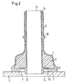
- Fig. 2 is different from that Fig. 1 only in that the material of the component 1 extends over the entire length of the tubular member and includes the material of the component 2 to the end 12, wherein the injection point 6 with the surface 7 of the ring member 11 facing away from the end 12 coincides.
- a theoretical leakage path in the axial direction around the entire component 2 would be much longer than in the first exemplary embodiment Fig. 1 except that a fluid line clamped on the pipe stub would prevent the escape of a fluid.
- the second embodiment has the same advantages as the first embodiment, except for a slightly thinner wall thickness of the component 2 in the end portion 9, which, however, could be chosen as well as the wall thickness of the end portion 9 in the first embodiment Fig. 1 ,
- the third embodiment according to Fig. 3 differs from the second embodiment according to Fig. 2 only in that in the second component 2, a third component 3 also from the injection point 6 of the second component 2 - after injecting the material of the component 2 in the still plastic soul of the material of the component 1 of the coincident with the end 12 Injection point 6 from - was injected into the still plastic soul of the material of the component 2 and in this case a significant part of the volume of the component 2 to close to the ring member 11 and the bottom 15 of the annular groove 14 fills.
- the material of the component 3 is in this case selected so that it increases at least one of the properties of strength, diffusion barrier and heat resistance of the component.
- the third component 3 may comprise predominantly one of the materials EVOH, PA, POM, PEN, PBT, PET, PBN, LCP, PPS, PPA, aliphatic polyketone and fluorothermoplastic.
- the first component 1 has an electrically conductive additive in all embodiments.
- the components 2 and 3 may have an electrically conductive additive.
- this addition may be graphite particles, carbon fibers or iron particles, especially fibrous iron particles.
- Electrically conductive fibers simultaneously cause a reinforcement of the material of the component in question.
- conductive fiber parts or in addition but also reinforcing particles of plastic, glass or mineral particles can be used.
- a component with a substantially U-shaped or trapezoidal cross-section may be provided as a lid or stopper which serves to close a blind opening or the like in the container.
- the injection point of the second and optionally third component would then preferably lie in the middle of the outside of the component.
- a further functional part can furthermore be injection-molded, e.g. a retaining clip for a fluid line or an electrical cable.
Landscapes
- Engineering & Computer Science (AREA)
- Mechanical Engineering (AREA)
- General Engineering & Computer Science (AREA)
- Manufacturing & Machinery (AREA)
- Sustainable Energy (AREA)
- Combustion & Propulsion (AREA)
- Transportation (AREA)
- Chemical & Material Sciences (AREA)
- Life Sciences & Earth Sciences (AREA)
- Sustainable Development (AREA)
- Injection Moulding Of Plastics Or The Like (AREA)
- Cooling, Air Intake And Gas Exhaust, And Fuel Tank Arrangements In Propulsion Units (AREA)
- Branch Pipes, Bends, And The Like (AREA)
Description
Die Erfindung bezieht sich auf ein Bauteil zum Verbinden einer Fluidleitung mit einer Öffnung eines überwiegend aus HDPE bestehenden Behälters gemäß dem Oberbegriff von Anspruch 1.The invention relates to a component for connecting a fluid line to an opening of a container consisting primarily of HDPE according to the preamble of claim 1.
Bei einem aus der
In
In
Der Erfindung liegt die Aufgabe zugrunde, ein Bauteil der eingangs genannten Art anzugeben, bei dem ein Austritt von Kraftstoff in höherem Maße verhindert wird.The invention has for its object to provide a component of the type mentioned, in which a leakage of fuel is prevented to a greater extent.
Die Lösung dieser Aufgabe besteht darin, daß das Material der ersten Komponente die zweite Komponente wenigstens bis zu einer Einspritzstelle einschließt, die einer am Behälter anzuschweißenden Fläche des Bauteils in möglichst großer bis größtmöglicher Entfernung abgekehrt ist und über die Material der zweiten Komponente in die noch plastische Seele des Materials der ersten Komponente eingespritzt worden ist.The solution to this problem is that the material of the first component includes the second component at least up to an injection point, which faces away from a surface of the component to be welded to the container in the largest possible distance and on the material of the second component in the still plastic Soul of the material of the first component has been injected.
Bei dieser Lösung ist es möglich, daß kein oder allenfalls ein Rand der Verbindungsfläche beider Komponenten dem Kraftstoff unmittelbar ausgesetzt ist. Eine Leckage entlang der Verbindungsflächen ist daher weitgehend bis völlig vermeidbar. Wenn der Abstand zwischen der am Behälter anzuschweißenden Fläche und der Einspritzstelle dem maximal möglichen entspricht, wird eine Leckage wegen des entsprechend langen Weges, den der Kohlenwasserstoff über die Verbindungsfläche zurücklegen müßte, verhindert. Dieser Weg wird außerdem durch eine Welligkeit der Verbindungsfläche, wie sie durch das Einspritzen an den Berührungsflächen der noch plastischen Materialien beider Komponenten hervorgerufen wird, nach Art einer Labyrinth-Dichtung verlängert. Die Welligkeit ergibt zugleich eine formschlüssige Verbindung. Sodann ist die Sperrfähigkeit im Überlappungsbereich der beiden Komponenten gegen ein Hindurchdiffundieren von Kraftstoffen weiterhin hoch, weil das Hindurchdiffundieren durch die nahezu diffusionsdichte zweite Komponente weitgehend verhindert wird. Außerdem ist die mechanische Festigkeit und Wärme-Formbeständigkeit im Überlappungsbereich sehr hoch. Darüber hinaus ermöglicht das Einspritzen des Materials der einen Komponente in die noch plastische Seele der anderen Komponente die Herstellung des Bauteils in demselben Formwerkzeug.In this solution, it is possible that no or at most an edge of the connecting surface of both components is directly exposed to the fuel. Leakage along the connecting surfaces is therefore largely or completely avoidable. If the distance between the surface to be welded to the container and the point of injection corresponds to the maximum possible, leakage is prevented because of the correspondingly long distance which the hydrocarbon would have to cover over the connection surface. This way is also characterized by a waviness of the bonding surface, as it is caused by the injection at the contact surfaces of the still plastic materials of both components, according to Art lengthened a labyrinth seal. The ripple also results in a positive connection. Then, the blocking ability in the overlap region of the two components against a fuel diffusing through continues to be high, because the diffusing through the nearly diffusion-tight second component is largely prevented. In addition, the mechanical strength and heat dimensional stability in the overlapping area is very high. In addition, the injection of the material of one component in the still plastic core of the other component allows the production of the component in the same mold.
Das Ringteil begrenzt zwischen sich und einem koaxialen rohrförmigen Fortsatz des Bauteils eine koaxiale Ringnut, und die axiale Dicke des Ringteils und die Tiefe der Ringnut sind so gewählt, daß die Dicke nach dem Anschweißen jener Fläche am Behälter wegen der teilweise seitlich ausweichenden Schmelze des Ringteils erheblich geringer als vor dem Anschweißen ist, aber der Boden der Ringnut weiterhin einen Abstand von dem Behälter aufweist. Beim Anschweißen des Ringteils am Behälter verringert sich mithin die Dicke des Ringteils durch die seitlich ausweichende Schmelze des Ringteils, so daß die einem Hindurchdiffundieren des Kraftstoffs nach dem Anschweißen noch verbleibende Ringfläche in der Ringnut sehr gering ist, aber dennoch das Material der zweiten Komponente eingeschlossen bleibt.The ring member defines between itself and a coaxial tubular extension of the component a coaxial annular groove, and the axial thickness of the ring member and the depth of the annular groove are chosen so that the thickness after welding of that surface on the container due to the partially laterally evasive melt of the ring member considerably less than before welding, but the bottom of the annular groove is still spaced from the container. When welding the ring member to the container thus reduces the thickness of the ring member by the laterally evasive melt of the ring member, so that the diffusion of a remaining fuel after welding still remaining annular surface in the annular groove is very low, but still the material of the second component is included ,
Das Material der ersten Komponente weist ein funktionalisiertes PE auf, das mit dem Material des Behälters und mit dem Material der zweiten Komponente verschmolzen ist.The material of the first component comprises a functionalized PE which is integral with the material of the container and merged with the material of the second component.
Die zweite Komponente weist wenigstens eines der Materialien EVOH, PA, PEN, PBT, PET, PBN, LCP, PPS, PPA, PP, aliphatisches Polyketon und Fluorthermoplast auf. Die Materialien EVOH, PA und PP gehen zumindest mit dem funktionalisierten PE der einen Komponente beim Einspritzen des Materials der anderen Komponente in das der ersten Komponente eine Schmelzverbindung ein, die nicht nur stoffschlüssig, sondern auch formschlüssig ist. Für diese und die übrigen Materialien gilt das gleiche für praktisch alle Polyolefine und/oder Copolymere nach entsprechender Modifikation.The second component comprises at least one of EVOH, PA, PEN, PBT, PET, PBN, LCP, PPS, PPA, PP, aliphatic polyketone and fluorothermoplastic. The materials EVOH, PA and PP, at least with the functionalized PE of one component when injecting the material of the other component into that of the first component, form a fusion bond which is not only materially bonded but also form-fitting. The same applies to these and the other materials for virtually all polyolefins and / or copolymers after appropriate modification.
Vorzugsweise ist dafür gesorgt, daß das Material der zweiten Komponente den größten Teil der Länge der Rohrwand ausfüllt. Dementsprechend ist das Bauteil über nahezu seine gesamte Länge ebenso diffusionsdicht und Stabil wie das Material der zweiten Komponente.Preferably, it is ensured that the material of the second component fills most of the length of the pipe wall. Accordingly, the component is as diffusion-tight and stable over almost its entire length as the material of the second component.
Dies ist besonders dann der Fall, wenn das Material der zweiten Komponente einen der am Behälter anzuschweißenden Fläche abgekehrten Endabschnitt des rohrförmigen Bauteils bildet.This is particularly the case when the material of the second component forms an end portion of the tubular member facing away from the surface to be welded to the container.
Andererseits kann sich bei einem weitgehend rohrförmigen Bauteil das Material der zweiten Komponente von einem die anzuschweißende Fläche aufweisenden Ringteil der ersten Komponente bis zu dem dieser Fläche abgekehrten Ende des rohrförmigen Bauteils erstrecken.On the other hand, in the case of a largely tubular component, the material of the second component may extend from a ring part of the first component having the surface to be welded to the end of the tubular component facing away from this surface.
Sodann kann dafür gesorgt sein, daß die zweite Komponente eine dritte Komponente einschließt, durch die wenigstens eine der Eigenschaften Festigkeit, Diffusionssperrfähigkeit und Wärme-Formbeständigkeit des Bauteils erhöht wird. Diese dritte Komponente kann ebenfalls dadurch in der zweiten Komponente angeordnet werden, daß ihr Material in die noch plastische Seele der zweiten Komponente eingespritzt wird. Auch dies kann in demselben Formwerkzeug erfolgen, in dem die erste und zweite Komponente geformt werden.Then it can be ensured that the second component includes a third component, by which at least one of the properties strength, diffusion barrier capability and heat dimensional stability of the component is increased. This third component can also be arranged in the second component by injecting its material into the still plastic core of the second component. Again, this can be done in the same mold in which the first and second components are formed.
Die dritte Komponente kann überwiegend eines der Materialien EVOH, PA, POM, PEN, PBT, PET, PBN, LCP, PPS, PPA, aliphatisches Polyketon und Fluorthermoplast aufweisen, so daß die Eigenschaften Festigkeit, Diffusionssperrfähigkeit und Wärme-Formbeständigkeit des Bauteils verbessert werden.The third component may predominantly comprise one of the materials EVOH, PA, POM, PEN, PBT, PET, PBN, LCP, PPS, PPA, aliphatic polyketone and fluorothermoplastic, so as to improve the strength, diffusion barrier and heat dimensional stability of the component.
Wenigstens die erste Komponente kann, in an sich bekannter Weise (
Das Bauteil kann im Querschnitt weitgehend U- oder trapezförmig sein, so daß es als Verschluß (Deckel oder Stopfen) für die Behälteröffnung dienen kann.The component may be substantially U- or trapezoidal in cross-section, so that it can serve as a closure (lid or plug) for the container opening.
An einem derart geformten Bauteil kann wenigstens ein weiteres Funktionsteil angespritzt sein, z.B. ein Halterungs-Clip, der z.B. zur Halterung einer Fluidleitung oder eines elektrischen Kabels dienen kann.At least one further functional part may be molded onto such a molded component, e.g. a retaining clip, e.g. can serve to hold a fluid line or an electric cable.
Die Erfindung und ihre Weiterbildungen werden nachstehend anhand der beiliegenden Zeichnungen bevorzugter Ausführungsbeispiele näher beschrieben. Darin stellen dar:
- Fig. 1
- einen Axialschnitt durch ein erfindungsgemäßes rohrförmiges Bauteil in einer Lage, in der es an einer Öffnung eines Behälters angeschweißt wird, um eine nicht dargestellte Fluidleitung mit der Behälteröffnung zu verbinden,
- Fig. 2
- ein zweites Ausführungsbeispiel eines erfindungsgemäßen Bauteils im Axialschnitt in der gleichen Lage wie das Bauteil nach
Fig. 1 , - Fig. 3
- ein drittes Ausführungsbeispiel eines erfindungsgemäßen Bauteils im Axialschnitt in der gleichen Lage wie das Bauteil nach
Fig. 1
- Fig. 1
- an axial section through a tubular member according to the invention in a position in which it is welded to an opening of a container to connect a fluid line, not shown, with the container opening,
- Fig. 2
- A second embodiment of a component according to the invention in axial section in the same position as the component after
Fig. 1 . - Fig. 3
- a third embodiment of a component according to the invention in axial section in the same position as the component after
Fig. 1
Das in
Der Behälter 5 ist in der Regel mehrschichtig, wobei seine äußere Schicht aus HDPE und eine mittlere Schicht aus einem Material besteht, das keinen Kraftstoff hindurchdiffundieren läßt.The
Die Materialien der ersten Komponente 1 und der zweiten Komponente 2 enthalten überwiegend thermoplastischen Kunststoff. Das Material der ersten Komponente 1 ist so gewählt, das es mit dem Material des Behälters 5 eine Schmelzverbindung durch Reibschweißen oder Spiegelschweißen eingeht. Gegebenenfalls hat es keine hinreichende Diffusionssperrfähigkeit gegenüber Kohlenwasserstoffen, wie Benzin oder Dieselöl. Außerdem hat es eine relativ geringe mechanische Festigkeit, weshalb es mitunter eine Verstärkung aufweist. Ferner hat es eine relativ hohe Quellfähigkeit gegenüber Kohlenwasserstoffen, wie Benzin oder Dieselöl. So weist die erste Komponente 1 ein Polyolefin, insbesondere ein funktionalisiertes PE (Polyethylen) auf, das mit dem Material des Behälters 5 verschmelzbar ist.The materials of the first component 1 and the
Das Material der zweiten Komponente 2 hat eine erheblich höhere Diffusionssperrfähigkeit und geringere Quellfähigkeit gegenüber Kohlenwasserstoffen der genannten Art und eine höhere mechanische Festigkeit, auch nach einer Kohlenwasserstoff-Einwirkung, sowie eine höhere Formbeständigkeit in der Wärme als das Material der ersten Komponente 1.The material of the
Die zweite Komponente 2 enthalt wenigstens eines der Materialien EVOH (Ethylenvenylalkohol), PA (Polyamid), POM (Polyoxymethylen), PBT (Polybutylenterephthalat), PET (Polyethylenterephthalat), PEN (Polyethylennaphthalat), PBN (Polybutylennaphthalat), LCP (Liquid Crystalline Polymer, d.h. flüssigkristallines Polymer), PPS (Polyphenylensulfid), PPA (Polyphthalamid, d.h. ein partiell aromatisches Polyamid), PP (Polylpropylen), aliphatisches Polyketon und Fluorthermoplast.The
Das rohrförmige Bauteil wird in der Weise hergestellt, daß das Material der ersten Komponente 1 die zweite Komponente 2 wenigstens bis zu einer Einspritzstelle 6 einschließt. Diese Einspritzstelle 6 ist einer am Behälter 5 anzuschweißenden Fläche 7 des Bauteils abgekehrt und hat von dieser einen relativ großen Abstand, der hier etwa der halben Länge des Rohrstutzens entspricht, vorzugsweise noch größer ist. Zunächst wird das Material der erste Komponente 1 in eine Kavität eines Formwerkzeugs eingespritzt, und bevor es vollständig ausgehärtet ist, wird in die noch plastische Seele des Materials der ersten Komponente 1 das Material der zweiten Komponente 2 an der Einspritzstelle 6 eingespritzt. Danach wird in einem weiteren Formwerkzeugteil ein der Fläche 7 abgekehrter Endabschnitt 9 mit einer in der Nähe der Einspritzstelle 6 liegenden Halterippe 10 von der Einspritzstelle 6 aus angespritzt. Die - Fluidleitung wird über die Halterippe und über die Einspritzstelle 6 hinweg auf den Stutzen aufgeschoben und mittels einer Schlauchschelle hinter der Halterippe 10 festgeklemmt. Nach dem Aushärten und Entformen hat das Bauteil die dargestellte Form mit einem die anzuschweißende Fläche 7 aufweisenden Ringteil 11 der ersten Komponente 1, wobei sich das Material der zweiten Komponente 2 von dem Ringteil 11 bis zu dem der Fläche 7 abgekehrten Ende 12 des Bauteils erstreckt.The tubular component is produced in such a way that the material of the first component 1 encloses the
Das Ringteil 11 begrenzt zwischen sich und einem koaxialen rohrförmigen Fortsatz 13, der zur Zentrierung beim Anschweißen des Bauteils am Behälter 5 in die Öffnung 4 ragt, eine koaxiale Ringnut 14, wobei die axiale Dicke des Ringteils 11 und die Tiefe der Ringnut 14 so gewählt sind, daß die Dicke nach dem Anschweißen der Fläche 7 am Behälter 5 wegen der teilweise seitlich in die Ringnut 14 und nach außen ausweichenden Schmelze des Ringteils 11 erheblich geringer ist, aber der Boden 15 in der Ringnut 14 weiterhin einen Abstand vom Behälter 5 aufweist, der etwa der verbliebenen axialen Dicke des Ringteils 11 entspricht.The
Das Material der Komponente 1 schließt mithin die Komponente 2 bis zur Einspritzstelle 6 vollständig ein und bildet anschließend zwischen der Einspritzstelle 6 und dem Ende 12 einen Endabschnitt 9, der nur aus dem Material der Komponente 2 besteht. Das Material der Komponente 1 hat zwar eine erheblich geringere Diffusionssperrfähigkeit als das Material der Komponente 2, doch kann es nur noch durch das nach dem Anschweißen der Fläche 7 am Behälter 5 erheblich flachere Ringteil 11 hindurchdiffundieren. Selbst wenn theoretisch ein Leckagepfad entlang der Grenz- oder Verbindungsfläche zwischen den beiden Komponenten 1 und 2 vom radial inneren Ende der Einspritzstelle 6 bis zum radial äußeren Ende der Einspritzstelle 6 auftreten sollte, wenn die Materialien der beiden Komponenten 1 und 2 nicht durchgehend über die gesamte Grenzfläche innig verschmolzen wären, wäre der Leckagepfad sehr lang, zumal die Grenzfläche beim Einspritzen des Materials der Komponente 2 in die noch plastische Seele der Komponente 1 aufgrund einer unterschiedlichen Dichte der beiden Materialien gewellt wird oder sich durch Wirbelbildung kräuselt, so daß der Leckagepfad tatsächlich erheblich länger als dargestellt wäre und die Grenzfläche eine Art Labyrinthdichtung bildet, über die mithin tatsächlich kein Kraftstoff durch Leckage austreten könnte. Hinzu kommt, daß eine auf dem Rohrstutzen festgeklemmte Fluidleitung, zum Beispiel ein Schlauch aus elastischem Material, die Einspritzstelle 6 dicht abdeckt. Da das Material der Komponente 2 eine hohe Formbeständigkeit in der Wärme, eine hohe mechanische Festigkeit und eine geringe Quellfähigkeit aufweist, gelten diese Eigenschaften im wesentlichen auch für das gesamte Bauteil, da das Material der zweiten Komponente den größten Teil des Gesamtvolumens des Bauteils ausfüllt. Zusätzlich zu der stoffschlüssigen Verbindung zwischen den Komponenten 1 und 2 bewirkt die Welligkeit ihrer Grenzfläche auch eine feste Formschlußverbindung.Consequently, the material of component 1 completely encloses
Das Ausführungsbeispiel nach
Im übrigen hat das zweite Ausführungsbeispiel die gleichen Vorteile wie das erste Ausführungsbeispiel, abgesehen von einer etwas dünneren Wanddicke der Komponente 2 im Endabschnitt 9, die jedoch ebenso gewählt werden könnte, wie die Wanddicke des Endabschnitts 9 bei dem ersten Ausführungsbeispiel nach
Das dritte Ausführungsbeispiel nach
Vorzugsweise hat die erste Komponente 1 bei allen Ausführungsbeispielen einen elektrisch leitfähigen Zusatz. Aber auch die Komponenten 2 und 3 können einen elektrisch leitfähigen Zusatz aufweisen. In allen Fällen kann es sich bei diesem Zusatz um Graphitteilchen, Kohlenstoffasern oder Eisenteilchen, insbesondere faserförmige Eisenteilchen, handeln. Durch den elektrisch leitfähigen Zusatz wird eine elektrische Aufladung durch eine Relativbewegung zwischen dem Kraftstoff und dem rohrförmigen Bauteil und damit die Gefahr einer Funkenentladung und Entzündung des Kraftstoffs vermieden.Preferably, the first component 1 has an electrically conductive additive in all embodiments. But also the
Elektrisch leitfähige Fasern bewirken gleichzeitig eine Verstärkung des Materials der betreffenden Komponente. Anstelle leitfähiger Faserteile oder zusätzlich können aber auch Verstärkungsteilchen aus Kunststoff, Glas oder Mineralpartikeln verwendet werden.Electrically conductive fibers simultaneously cause a reinforcement of the material of the component in question. Instead of conductive fiber parts or in addition but also reinforcing particles of plastic, glass or mineral particles can be used.
Anstelle des dargestellten rohrförmigen Bauteils bzw. Stutzens kann ein Bauteil mit einem weitgehend U- oder trapezförmigen Querschnitt als Deckel oder Stopfen vorgesehen sein, der zum Verschließen einer Blindöffnung oder dergleichen im Behälter dient. Die Einspritzstelle der zweiten und gegebenenfalls dritten Komponente würde dann vorzugsweise in der Mitte der Außenseite des Bauteils liegen. An dem U- oder trapezförmigen Bauteil kann darüber hinaus ein weiteres Funktionsteil angespritzt sein, z.B. ein Halterungs-Clip für eine Fluidleitung oder ein elektrisches Kabel.Instead of the illustrated tubular component or connecting piece, a component with a substantially U-shaped or trapezoidal cross-section may be provided as a lid or stopper which serves to close a blind opening or the like in the container. The injection point of the second and optionally third component would then preferably lie in the middle of the outside of the component. On the U- or trapezoidal component, a further functional part can furthermore be injection-molded, e.g. a retaining clip for a fluid line or an electrical cable.
Claims (4)
- Largely tubular structural member for connecting a fluid pipe to an opening (4) of a container (5) consisting predominantly of HDPE, wherein the structural member has at least one first and one second component (1,2) consisting in each case predominantly of thermoplastic material, the material of the first component (1) enters into a fused joint with the material of the container by welding, but does not have sufficient diffusion barrier capability with respect to hydrocarbons, such as motor fuel or diesel fuel, and the material of the second component (2) has a higher diffusion barrier capability and lower swelling capacity with respect to hydrocarbons and a higher mechanical strength, even after action of hydrocarbon, and a higher dimensional stability in heat than the material of the first component (1), wherein the material of the first component (1) surrounds the second component (2) by a surface (7) of the structural member to be welded onto the container (5) at least up to an injection point (6), via which material of the second component (2) has been injected into the still plastic core of the material of the first component (1) and which is selected so that in operation of the structural member, no edge or if need be one edge of the connecting surface of both components (1, 2) lying on the inner side of the structural member is exposed directly to the hydrocarbon, characterised in that the second component (2) comprises at least one of the materials EVOH, PA, PEN, PBT, PET, PBN, LCP, PPS, PPA, PP, aliphatic polyketone and fluoro-thermoplastic material, in that the first component (1) has such a functionalised PE that it is fused integrally with the material of the second component (2) and can be fused with the material of the container, in that the material of the second component (2) extends from an annular part (11) of the first component (1) having the surface (7) to be welded on up to the injection point (6) and in that the annular part (11) between it and a coaxial tubular extension (13) of the structural member defines a coaxial annular groove (14) and the axial thickness of the annular part (11) and the depth of the annular groove (14) are selected so that the thickness after welding of that surface (7) onto the container (5) is considerably lower because of the partly laterally escaping melt of the annular part (11), but the base of the annular groove (14) also has a distance from the container (5).
- Structural member according to claim 1, characterised in that the material of the second component (2) fills out the largest part of the length of the pipe wall.
- Structural member according to claim 2, characterised in that the material of the second component (2) forms an end section (9) of the tubular structural member facing away from the surface (7) to be welded onto the container.
- Structural member according to one of claims 1 to 3, characterised in that the second component (2) surrounds a third component (3), by means of which at least one of the properties strength, diffusion barrier capability and thermal dimensional stability of the structural member is increased.
Priority Applications (4)
| Application Number | Priority Date | Filing Date | Title |
|---|---|---|---|
| EP20070006360 EP1829663B1 (en) | 2002-09-03 | 2003-05-28 | Component for connecting a fluid duct to an opening on a plastic container |
| US10/651,817 US7066498B2 (en) | 2002-09-03 | 2003-08-28 | Part for connecting a fluid line to an opening of a container comprising plastic material or for closing the opening |
| JP2003308855A JP2004263852A (en) | 2002-09-03 | 2003-09-01 | Part for connecting fluid line to opening of container comprising plastic material or for closing the opening |
| US11/418,432 US7631903B2 (en) | 2002-09-03 | 2006-05-04 | Part for connecting a fluid line to an opening of a container comprising plastic material or for closing the opening |
Applications Claiming Priority (2)
| Application Number | Priority Date | Filing Date | Title |
|---|---|---|---|
| DE2002141286 DE10241286B4 (en) | 2002-09-03 | 2002-09-03 | Component for connecting a fluid conduit with an opening of a plastic-containing container or for closing the opening |
| DE10241286 | 2002-09-03 |
Related Child Applications (1)
| Application Number | Title | Priority Date | Filing Date |
|---|---|---|---|
| EP20070006360 Division EP1829663B1 (en) | 2002-09-03 | 2003-05-28 | Component for connecting a fluid duct to an opening on a plastic container |
Publications (2)
| Publication Number | Publication Date |
|---|---|
| EP1396326A1 EP1396326A1 (en) | 2004-03-10 |
| EP1396326B1 true EP1396326B1 (en) | 2008-11-05 |
Family
ID=31502448
Family Applications (2)
| Application Number | Title | Priority Date | Filing Date |
|---|---|---|---|
| EP20070006360 Expired - Lifetime EP1829663B1 (en) | 2002-09-03 | 2003-05-28 | Component for connecting a fluid duct to an opening on a plastic container |
| EP20030011989 Expired - Lifetime EP1396326B1 (en) | 2002-09-03 | 2003-05-28 | Connector between a fluid conduit and the opening of a resin container |
Family Applications Before (1)
| Application Number | Title | Priority Date | Filing Date |
|---|---|---|---|
| EP20070006360 Expired - Lifetime EP1829663B1 (en) | 2002-09-03 | 2003-05-28 | Component for connecting a fluid duct to an opening on a plastic container |
Country Status (4)
| Country | Link |
|---|---|
| US (2) | US7066498B2 (en) |
| EP (2) | EP1829663B1 (en) |
| JP (1) | JP2004263852A (en) |
| DE (2) | DE10241286B4 (en) |
Cited By (2)
| Publication number | Priority date | Publication date | Assignee | Title |
|---|---|---|---|---|
| CN101612776B (en) * | 2009-07-14 | 2012-06-27 | 亚普汽车部件股份有限公司 | Special mould for plastic fuel tank connector |
| CN103162019A (en) * | 2011-12-13 | 2013-06-19 | 福特全球技术公司 | Sealing a fuel tank against hydrocarbon permeation |
Families Citing this family (27)
| Publication number | Priority date | Publication date | Assignee | Title |
|---|---|---|---|---|
| DE10161416A1 (en) * | 2001-12-13 | 2003-06-18 | Roth Werke Gmbh | Containers, in particular inner pallet containers |
| DE10241286B4 (en) * | 2002-09-03 | 2004-07-22 | Rasmussen Gmbh | Component for connecting a fluid conduit with an opening of a plastic-containing container or for closing the opening |
| DE10309275A1 (en) * | 2002-09-03 | 2004-03-25 | Rasmussen Gmbh | Improved connector joining vehicle fuel tank to fuel line, comprises three components with second component largely enclosed by material of third component |
| DE10324471B3 (en) * | 2003-05-30 | 2004-12-16 | Rasmussen Gmbh | Pipe-like neck |
| GB0327043D0 (en) * | 2003-11-18 | 2004-04-07 | Rolls Royce Plc | A method of manufacturing an article by applying heat and pressure, a method of connecting a pipe to a sealed assembly and a connector for use therein |
| DE102004042847A1 (en) | 2004-09-04 | 2006-03-09 | Rasmussen Gmbh | Component with tubular section |
| DE102005042678A1 (en) | 2004-12-24 | 2006-07-06 | Rasmussen Gmbh | Method for producing a neck |
| JP4564858B2 (en) * | 2005-02-08 | 2010-10-20 | 八千代工業株式会社 | Fuel tank structure |
| US20070222213A1 (en) * | 2006-03-24 | 2007-09-27 | Florencia Andersen | Thermoplastic element for protection against corrosion in the thermofusion coupling of a thermoplastic tube |
| JP4991172B2 (en) * | 2006-03-27 | 2012-08-01 | 株式会社ニフコ | Fuel tank connector |
| FR2900092A1 (en) * | 2006-04-21 | 2007-10-26 | Inergy Automotive Systems Res | PROCESS FOR MANUFACTURING A FUEL TANK |
| WO2008008294A2 (en) * | 2006-07-14 | 2008-01-17 | Continental Automotive Systems Us, Inc. | Interface o-ring seal for low permeation flange of a fuel supply unit |
| US8070187B2 (en) * | 2006-08-21 | 2011-12-06 | Continental Automotive Systems Us, Inc. | Interface hose seal for low permeation flange of a fuel supply unit |
| DE102009016451B3 (en) * | 2009-04-04 | 2011-01-20 | Protechna S.A. | Removal fitting with a valve housing made of plastic for transport and storage containers for liquids and method for producing the electrically grounded connection flange for attachment of the removal fitting to the discharge neck of the inner container of the transport and storage container |
| DE102009050808A1 (en) * | 2009-10-27 | 2011-04-28 | Bayerische Motoren Werke Aktiengesellschaft | Filling device for fuel tank in motor vehicle, has additional electrically conducting connection provided at outer surface of pipe and penetrating pipe radially without impairing its diffusion blocking capability in relation to fuel |
| DE202009016927U1 (en) * | 2009-12-15 | 2010-04-29 | Feichtinger, Reinhard | Fuel attachment |
| US20110284126A1 (en) * | 2010-04-20 | 2011-11-24 | Stant Usa Corp. | Mount for inlet check valve |
| AT511645B1 (en) * | 2011-07-05 | 2015-05-15 | Praher Kunststofftechnik Gmbh | SANDWICH INJECTION MOLDING AND FORMING COMPRISING A LAYERED COMPOSITE PRODUCED BY THE SANDWICH MOLDING METHOD |
| CN104411962B (en) | 2012-07-02 | 2017-09-22 | 诺玛美国控股有限责任公司 | Fuel line connector and its manufacture method |
| US9248587B2 (en) * | 2012-07-05 | 2016-02-02 | General Electric Company | Apparatus for manufacturing a flanged composite component and methods of manufacturing the same |
| JP6442301B2 (en) * | 2015-01-23 | 2018-12-19 | ユニプレス株式会社 | Fuel pipe mounting structure for automobile metal fuel tank |
| EP3127735B1 (en) * | 2015-08-07 | 2017-07-05 | Magna Steyr Fuel Systems GesmbH | Fuel filling neck for a vehicle with improved diffusion strength |
| US10883640B2 (en) | 2016-06-24 | 2021-01-05 | Eaton Intelligent Power Limited | Fluid couplings, systems, and methods |
| US11149883B2 (en) | 2016-06-24 | 2021-10-19 | Eaton Intelligent Power Limited | Fluid couplings, systems, and methods |
| FR3077013B1 (en) * | 2018-01-24 | 2023-12-15 | Aptar France Sas | FLUID PRODUCT DISTRIBUTION DEVICE. |
| CN111255955A (en) * | 2018-11-30 | 2020-06-09 | 上海英泰塑胶股份有限公司 | High-pressure-resistant injection-molded pipe fitting with embedded reinforced core piece |
| DE102019209914A1 (en) * | 2019-07-05 | 2021-01-07 | Contitech Kühner Gmbh & Cie. Kg | Pipeline |
Family Cites Families (34)
| Publication number | Priority date | Publication date | Assignee | Title |
|---|---|---|---|---|
| US653280A (en) * | 1900-03-10 | 1900-07-10 | Friedrich Wilhelm Barthels | Flanged tube. |
| US1978609A (en) * | 1933-06-24 | 1934-10-30 | Smith Corp A O | Welded manway for pressure vessels |
| US2922932A (en) * | 1956-06-25 | 1960-01-26 | Sessions Clock Co | Magnetic coils |
| US4047061A (en) * | 1973-03-16 | 1977-09-06 | P. R. Mallory & Co., Inc. | Coil protector for permanent magnet synchronous motor |
| US4613168A (en) * | 1982-03-04 | 1986-09-23 | Avon Industrial Polymers Limited | Method of making branches in hoses |
| DE3828696A1 (en) * | 1988-08-24 | 1990-03-01 | Bayer Ag | ELASTOMERMODIFIED CARBOHYLATED POLYARYLENE SULFIDE BLENDS |
| DE19519481A1 (en) * | 1995-05-27 | 1996-11-28 | Huels Chemische Werke Ag | Multi-layer plastic fuel filter with antistatic properties |
| DE19535413C1 (en) * | 1995-09-23 | 1996-10-02 | Rasmussen Gmbh | Tube-like nozzle for connection to vessel of HDPE with thermoplastic part |
| US5951059A (en) * | 1996-07-24 | 1999-09-14 | Tokai Rubber Industries Ltd. | Tube connector device having connector holder made of elastomer |
| US5837180A (en) * | 1997-02-05 | 1998-11-17 | Fluoroware, Inc. | Composite plastic sanitary fitting |
| US5912518A (en) * | 1997-10-22 | 1999-06-15 | Misik; Michael F. | Motor coil assembly |
| DE19953746C2 (en) * | 1999-06-21 | 2001-10-04 | Rasmussen Gmbh | Method of making a nozzle |
| DE10048973A1 (en) * | 1999-09-27 | 2001-07-05 | Heiner Becker | Plastic pipe fitting, e.g. for welded and mechanical joints at opposite ends, comprises a single two component injection molding |
| DE19951670A1 (en) * | 1999-10-27 | 2001-05-03 | Ticona Gmbh | Weldable components made of polyacetal |
| CA2334149C (en) * | 2000-02-03 | 2005-05-10 | Stant Manufacturing Inc. | Weldable mount for fuel systems component |
| US6652699B1 (en) * | 2000-02-17 | 2003-11-25 | Salflex Polymers Ltd. | Flanged member with barrier layer |
| JP3824212B2 (en) * | 2000-11-17 | 2006-09-20 | 豊田合成株式会社 | Valve with fuel tank |
| JP3994662B2 (en) * | 2000-03-30 | 2007-10-24 | 豊田合成株式会社 | Fuel shut-off valve |
| DE10025707A1 (en) * | 2000-05-26 | 2001-11-29 | Degussa | Multi-layer, reinforced plastic connection element with antistatic properties |
| US6289915B1 (en) * | 2000-06-06 | 2001-09-18 | Visteon Global Technologies, Inc. | Permeation and leak preventative design for fuel tank attachments |
| JP3777290B2 (en) * | 2000-06-14 | 2006-05-24 | 日本電産サンキョー株式会社 | motor |
| JP3914733B2 (en) * | 2000-11-02 | 2007-05-16 | 株式会社ニフコ | Fuel tank connector |
| DE10056974C1 (en) * | 2000-11-17 | 2002-01-17 | Rasmussen Gmbh | Tubular pouring spout for a petrol or diesel oil container made from thermoplastic, especially polyethylene, has tubular section made from plastic with low swelling properties and ring with conical cross-section which fits around it |
| DE10062997A1 (en) * | 2000-12-16 | 2002-07-18 | Rasmussen Gmbh | Tubular connector piece for attachment to opening of container comprises first and second parts made of materials capable of chemically combining across their contact surfaces |
| US6640783B2 (en) * | 2001-02-15 | 2003-11-04 | Delphi Technologies, Inc. | Composite fuel rail with integral damping and a co-injected non-permeation layer |
| JP3893987B2 (en) * | 2001-03-16 | 2007-03-14 | 東海ゴム工業株式会社 | Molding method for tank joint parts and ring-shaped resin moldings |
| US6612324B2 (en) * | 2001-03-19 | 2003-09-02 | Saturn Electronics & Engineering, Inc. | Fill limit vapor valve with variable vapor venting capability |
| US6662820B2 (en) * | 2001-12-06 | 2003-12-16 | Stant Manufacturing Inc. | Weldable mount for fuel system component |
| JP3821224B2 (en) * | 2002-03-15 | 2006-09-13 | 日産自動車株式会社 | Welding method of fuel enclosure and welding parts |
| JP3909837B2 (en) * | 2002-08-23 | 2007-04-25 | 豊田合成株式会社 | Fuel tank fuel spill regulating device |
| DE10309275A1 (en) * | 2002-09-03 | 2004-03-25 | Rasmussen Gmbh | Improved connector joining vehicle fuel tank to fuel line, comprises three components with second component largely enclosed by material of third component |
| DE10241286B4 (en) * | 2002-09-03 | 2004-07-22 | Rasmussen Gmbh | Component for connecting a fluid conduit with an opening of a plastic-containing container or for closing the opening |
| US20040155457A1 (en) * | 2003-02-12 | 2004-08-12 | Maersk Medical A/S | Connecting element comprising a first body and a method for injection moulding a connecting element |
| US6840264B1 (en) * | 2003-08-13 | 2005-01-11 | Visteon Global Technologies, Inc. | Fuel tank venting system for reduced fuel permeation |
-
2002
- 2002-09-03 DE DE2002141286 patent/DE10241286B4/en not_active Expired - Lifetime
-
2003
- 2003-05-28 DE DE50310737T patent/DE50310737D1/en not_active Expired - Lifetime
- 2003-05-28 EP EP20070006360 patent/EP1829663B1/en not_active Expired - Lifetime
- 2003-05-28 EP EP20030011989 patent/EP1396326B1/en not_active Expired - Lifetime
- 2003-08-28 US US10/651,817 patent/US7066498B2/en not_active Expired - Lifetime
- 2003-09-01 JP JP2003308855A patent/JP2004263852A/en active Pending
-
2006
- 2006-05-04 US US11/418,432 patent/US7631903B2/en active Active
Cited By (3)
| Publication number | Priority date | Publication date | Assignee | Title |
|---|---|---|---|---|
| CN101612776B (en) * | 2009-07-14 | 2012-06-27 | 亚普汽车部件股份有限公司 | Special mould for plastic fuel tank connector |
| CN103162019A (en) * | 2011-12-13 | 2013-06-19 | 福特全球技术公司 | Sealing a fuel tank against hydrocarbon permeation |
| CN103162019B (en) * | 2011-12-13 | 2016-09-07 | 福特全球技术公司 | Seal fuel tank to prevent hydrocarbon infiltration |
Also Published As
| Publication number | Publication date |
|---|---|
| DE10241286A1 (en) | 2004-03-18 |
| US20060197341A1 (en) | 2006-09-07 |
| US7631903B2 (en) | 2009-12-15 |
| EP1829663A1 (en) | 2007-09-05 |
| EP1829663B1 (en) | 2013-05-15 |
| DE10241286B4 (en) | 2004-07-22 |
| JP2004263852A (en) | 2004-09-24 |
| DE50310737D1 (en) | 2008-12-18 |
| US7066498B2 (en) | 2006-06-27 |
| US20040051305A1 (en) | 2004-03-18 |
| EP1396326A1 (en) | 2004-03-10 |
Similar Documents
| Publication | Publication Date | Title |
|---|---|---|
| EP1396326B1 (en) | Connector between a fluid conduit and the opening of a resin container | |
| EP2030755B1 (en) | Method for manufacturing a support | |
| DE102006005828B4 (en) | Connecting pipe for a fuel tank | |
| EP1063078B1 (en) | Process for making a branch stub | |
| EP1852390B1 (en) | Discharge valve for a container, in particular a pallet container | |
| EP2652276B1 (en) | Liquid extraction module, liquid tank | |
| WO2008138709A2 (en) | Connecting device for moving fluids | |
| DE102005050564A1 (en) | Welding connector for a fuel tank | |
| EP1632380B1 (en) | Part with tubular section | |
| DE60124038T2 (en) | Plastic fuel tank with arrangement for fuel-tight welding of a component | |
| EP1396327B1 (en) | Fitting for the connection of a fuel tank with a fluid conduit and process for its manufacture | |
| EP2129708B1 (en) | Fuel tank attachment and method for producing a fuel tank attachment | |
| DE10324471B3 (en) | Pipe-like neck | |
| DE10062997A1 (en) | Tubular connector piece for attachment to opening of container comprises first and second parts made of materials capable of chemically combining across their contact surfaces | |
| DE10056974C1 (en) | Tubular pouring spout for a petrol or diesel oil container made from thermoplastic, especially polyethylene, has tubular section made from plastic with low swelling properties and ring with conical cross-section which fits around it | |
| EP2512857B1 (en) | Fuel tank accessory and method for producing a fuel tank accessory | |
| DE19951670A1 (en) | Weldable components made of polyacetal | |
| DE202007006954U1 (en) | Connecting device for flow media | |
| DE102007026805B4 (en) | Media-tight component, in particular vent pipe, comprising at least one metal part and at least one plastic part | |
| DE102020128011A1 (en) | Sandwich motor vehicle tank with barrier film and molded inner and outer tank walls | |
| WO2011073146A1 (en) | Fuel line and fuel tank system | |
| EP1288053A2 (en) | Plastic fuel tank | |
| DE102021106280A1 (en) | Tank shell containing barrier film with permeation-proof connection formation for connecting a separate line component | |
| DE102017114581A1 (en) | SEALED ELECTRICAL MODULE FOR A MOTOR VEHICLE |
Legal Events
| Date | Code | Title | Description |
|---|---|---|---|
| PUAI | Public reference made under article 153(3) epc to a published international application that has entered the european phase |
Free format text: ORIGINAL CODE: 0009012 |
|
| AK | Designated contracting states |
Kind code of ref document: A1 Designated state(s): AT BE BG CH CY CZ DE DK EE ES FI FR GB GR HU IE IT LI LU MC NL PT RO SE SI SK TR |
|
| AX | Request for extension of the european patent |
Extension state: AL LT LV MK |
|
| 17P | Request for examination filed |
Effective date: 20040429 |
|
| 17Q | First examination report despatched |
Effective date: 20040519 |
|
| AKX | Designation fees paid |
Designated state(s): DE FR GB |
|
| 17Q | First examination report despatched |
Effective date: 20040519 |
|
| RAP1 | Party data changed (applicant data changed or rights of an application transferred) |
Owner name: NORMA GERMANY GMBH |
|
| GRAP | Despatch of communication of intention to grant a patent |
Free format text: ORIGINAL CODE: EPIDOSNIGR1 |
|
| GRAS | Grant fee paid |
Free format text: ORIGINAL CODE: EPIDOSNIGR3 |
|
| GRAA | (expected) grant |
Free format text: ORIGINAL CODE: 0009210 |
|
| AK | Designated contracting states |
Kind code of ref document: B1 Designated state(s): DE FR GB |
|
| REG | Reference to a national code |
Ref country code: GB Ref legal event code: FG4D Free format text: NOT ENGLISH |
|
| REF | Corresponds to: |
Ref document number: 50310737 Country of ref document: DE Date of ref document: 20081218 Kind code of ref document: P |
|
| PLBE | No opposition filed within time limit |
Free format text: ORIGINAL CODE: 0009261 |
|
| STAA | Information on the status of an ep patent application or granted ep patent |
Free format text: STATUS: NO OPPOSITION FILED WITHIN TIME LIMIT |
|
| 26N | No opposition filed |
Effective date: 20090806 |
|
| REG | Reference to a national code |
Ref country code: FR Ref legal event code: PLFP Year of fee payment: 13 |
|
| REG | Reference to a national code |
Ref country code: DE Ref legal event code: R082 Ref document number: 50310737 Country of ref document: DE Representative=s name: PATENTANWAELTE OLBRICHT, BUCHHOLD, KEULERTZ PA, DE |
|
| REG | Reference to a national code |
Ref country code: FR Ref legal event code: PLFP Year of fee payment: 14 |
|
| REG | Reference to a national code |
Ref country code: FR Ref legal event code: PLFP Year of fee payment: 15 |
|
| REG | Reference to a national code |
Ref country code: FR Ref legal event code: PLFP Year of fee payment: 16 |
|
| PGFP | Annual fee paid to national office [announced via postgrant information from national office to epo] |
Ref country code: GB Payment date: 20220527 Year of fee payment: 20 Ref country code: FR Payment date: 20220525 Year of fee payment: 20 Ref country code: DE Payment date: 20220527 Year of fee payment: 20 |
|
| REG | Reference to a national code |
Ref country code: DE Ref legal event code: R071 Ref document number: 50310737 Country of ref document: DE |
|
| REG | Reference to a national code |
Ref country code: GB Ref legal event code: PE20 Expiry date: 20230527 |
|
| PG25 | Lapsed in a contracting state [announced via postgrant information from national office to epo] |
Ref country code: GB Free format text: LAPSE BECAUSE OF EXPIRATION OF PROTECTION Effective date: 20230527 |