EP1632380B1 - Part with tubular section - Google Patents
Part with tubular section Download PDFInfo
- Publication number
- EP1632380B1 EP1632380B1 EP05016822A EP05016822A EP1632380B1 EP 1632380 B1 EP1632380 B1 EP 1632380B1 EP 05016822 A EP05016822 A EP 05016822A EP 05016822 A EP05016822 A EP 05016822A EP 1632380 B1 EP1632380 B1 EP 1632380B1
- Authority
- EP
- European Patent Office
- Prior art keywords
- annular surface
- injected
- reinforced
- polyethylene
- plastic
- Prior art date
- Legal status (The legal status is an assumption and is not a legal conclusion. Google has not performed a legal analysis and makes no representation as to the accuracy of the status listed.)
- Expired - Fee Related
Links
- 239000000463 material Substances 0.000 claims description 108
- 239000004952 Polyamide Substances 0.000 claims description 24
- 229920002647 polyamide Polymers 0.000 claims description 24
- -1 polyethylene Polymers 0.000 claims description 18
- 239000012530 fluid Substances 0.000 claims description 16
- 239000004698 Polyethylene Substances 0.000 claims description 15
- 229920000573 polyethylene Polymers 0.000 claims description 15
- 239000004743 Polypropylene Substances 0.000 claims description 8
- 229920001155 polypropylene Polymers 0.000 claims description 8
- 239000004734 Polyphenylene sulfide Substances 0.000 claims description 5
- 229920000139 polyethylene terephthalate Polymers 0.000 claims description 5
- 239000005020 polyethylene terephthalate Substances 0.000 claims description 5
- 229920006324 polyoxymethylene Polymers 0.000 claims description 5
- 229920000069 polyphenylene sulfide Polymers 0.000 claims description 5
- 229920001169 thermoplastic Polymers 0.000 claims description 4
- 239000004416 thermosoftening plastic Substances 0.000 claims description 4
- 239000004715 ethylene vinyl alcohol Substances 0.000 claims description 3
- 229920000728 polyester Polymers 0.000 claims description 3
- 239000011112 polyethylene naphthalate Substances 0.000 claims description 3
- 229920000098 polyolefin Polymers 0.000 claims description 3
- 229920002725 thermoplastic elastomer Polymers 0.000 claims description 3
- 229920006346 thermoplastic polyester elastomer Polymers 0.000 claims description 3
- 229920002994 synthetic fiber Polymers 0.000 claims 4
- 229920003023 plastic Polymers 0.000 description 33
- 239000004033 plastic Substances 0.000 description 33
- 208000015943 Coeliac disease Diseases 0.000 description 32
- 238000005266 casting Methods 0.000 description 9
- 239000003365 glass fiber Substances 0.000 description 9
- 229930195733 hydrocarbon Natural products 0.000 description 9
- 150000002430 hydrocarbons Chemical class 0.000 description 9
- 238000002347 injection Methods 0.000 description 8
- 239000007924 injection Substances 0.000 description 8
- 238000009792 diffusion process Methods 0.000 description 6
- 230000004888 barrier function Effects 0.000 description 5
- 229920001903 high density polyethylene Polymers 0.000 description 5
- 239000004700 high-density polyethylene Substances 0.000 description 5
- 230000035515 penetration Effects 0.000 description 5
- 229920000642 polymer Polymers 0.000 description 4
- 239000012815 thermoplastic material Substances 0.000 description 4
- 229930040373 Paraformaldehyde Natural products 0.000 description 3
- 229920001971 elastomer Polymers 0.000 description 3
- 239000000806 elastomer Substances 0.000 description 3
- 230000004048 modification Effects 0.000 description 3
- 238000012986 modification Methods 0.000 description 3
- 230000002787 reinforcement Effects 0.000 description 3
- 239000004215 Carbon black (E152) Substances 0.000 description 2
- 230000015572 biosynthetic process Effects 0.000 description 2
- 238000005520 cutting process Methods 0.000 description 2
- 239000000446 fuel Substances 0.000 description 2
- 230000004927 fusion Effects 0.000 description 2
- 239000002990 reinforced plastic Substances 0.000 description 2
- 230000007704 transition Effects 0.000 description 2
- 238000003466 welding Methods 0.000 description 2
- 229920000219 Ethylene vinyl alcohol Polymers 0.000 description 1
- 239000007977 PBT buffer Substances 0.000 description 1
- 230000001476 alcoholic effect Effects 0.000 description 1
- 150000001875 compounds Chemical class 0.000 description 1
- 239000000498 cooling water Substances 0.000 description 1
- 238000011161 development Methods 0.000 description 1
- 230000018109 developmental process Effects 0.000 description 1
- 239000002283 diesel fuel Substances 0.000 description 1
- RZXDTJIXPSCHCI-UHFFFAOYSA-N hexa-1,5-diene-2,5-diol Chemical compound OC(=C)CCC(O)=C RZXDTJIXPSCHCI-UHFFFAOYSA-N 0.000 description 1
- 238000004519 manufacturing process Methods 0.000 description 1
- 238000000034 method Methods 0.000 description 1
- 239000012768 molten material Substances 0.000 description 1
- 230000002093 peripheral effect Effects 0.000 description 1
- 229920003207 poly(ethylene-2,6-naphthalate) Polymers 0.000 description 1
- 229920001707 polybutylene terephthalate Polymers 0.000 description 1
- 239000000243 solution Substances 0.000 description 1
- 239000002699 waste material Substances 0.000 description 1
Images


Classifications
-
- B—PERFORMING OPERATIONS; TRANSPORTING
- B29—WORKING OF PLASTICS; WORKING OF SUBSTANCES IN A PLASTIC STATE IN GENERAL
- B29C—SHAPING OR JOINING OF PLASTICS; SHAPING OF MATERIAL IN A PLASTIC STATE, NOT OTHERWISE PROVIDED FOR; AFTER-TREATMENT OF THE SHAPED PRODUCTS, e.g. REPAIRING
- B29C45/00—Injection moulding, i.e. forcing the required volume of moulding material through a nozzle into a closed mould; Apparatus therefor
- B29C45/16—Making multilayered or multicoloured articles
- B29C45/1642—Making multilayered or multicoloured articles having a "sandwich" structure
-
- B—PERFORMING OPERATIONS; TRANSPORTING
- B29—WORKING OF PLASTICS; WORKING OF SUBSTANCES IN A PLASTIC STATE IN GENERAL
- B29C—SHAPING OR JOINING OF PLASTICS; SHAPING OF MATERIAL IN A PLASTIC STATE, NOT OTHERWISE PROVIDED FOR; AFTER-TREATMENT OF THE SHAPED PRODUCTS, e.g. REPAIRING
- B29C45/00—Injection moulding, i.e. forcing the required volume of moulding material through a nozzle into a closed mould; Apparatus therefor
- B29C45/17—Component parts, details or accessories; Auxiliary operations
- B29C45/26—Moulds
- B29C45/27—Sprue channels ; Runner channels or runner nozzles
- B29C45/2701—Details not specific to hot or cold runner channels
- B29C45/2708—Gates
-
- B—PERFORMING OPERATIONS; TRANSPORTING
- B29—WORKING OF PLASTICS; WORKING OF SUBSTANCES IN A PLASTIC STATE IN GENERAL
- B29K—INDEXING SCHEME ASSOCIATED WITH SUBCLASSES B29B, B29C OR B29D, RELATING TO MOULDING MATERIALS OR TO MATERIALS FOR MOULDS, REINFORCEMENTS, FILLERS OR PREFORMED PARTS, e.g. INSERTS
- B29K2995/00—Properties of moulding materials, reinforcements, fillers, preformed parts or moulds
- B29K2995/0037—Other properties
- B29K2995/0068—Permeability to liquids; Adsorption
- B29K2995/0069—Permeability to liquids; Adsorption non-permeable
-
- B—PERFORMING OPERATIONS; TRANSPORTING
- B29—WORKING OF PLASTICS; WORKING OF SUBSTANCES IN A PLASTIC STATE IN GENERAL
- B29K—INDEXING SCHEME ASSOCIATED WITH SUBCLASSES B29B, B29C OR B29D, RELATING TO MOULDING MATERIALS OR TO MATERIALS FOR MOULDS, REINFORCEMENTS, FILLERS OR PREFORMED PARTS, e.g. INSERTS
- B29K2995/00—Properties of moulding materials, reinforcements, fillers, preformed parts or moulds
- B29K2995/0037—Other properties
- B29K2995/0082—Flexural strength; Flexion stiffness
-
- B—PERFORMING OPERATIONS; TRANSPORTING
- B29—WORKING OF PLASTICS; WORKING OF SUBSTANCES IN A PLASTIC STATE IN GENERAL
- B29K—INDEXING SCHEME ASSOCIATED WITH SUBCLASSES B29B, B29C OR B29D, RELATING TO MOULDING MATERIALS OR TO MATERIALS FOR MOULDS, REINFORCEMENTS, FILLERS OR PREFORMED PARTS, e.g. INSERTS
- B29K2995/00—Properties of moulding materials, reinforcements, fillers, preformed parts or moulds
- B29K2995/0037—Other properties
- B29K2995/0083—Creep
-
- Y—GENERAL TAGGING OF NEW TECHNOLOGICAL DEVELOPMENTS; GENERAL TAGGING OF CROSS-SECTIONAL TECHNOLOGIES SPANNING OVER SEVERAL SECTIONS OF THE IPC; TECHNICAL SUBJECTS COVERED BY FORMER USPC CROSS-REFERENCE ART COLLECTIONS [XRACs] AND DIGESTS
- Y10—TECHNICAL SUBJECTS COVERED BY FORMER USPC
- Y10T—TECHNICAL SUBJECTS COVERED BY FORMER US CLASSIFICATION
- Y10T428/00—Stock material or miscellaneous articles
- Y10T428/13—Hollow or container type article [e.g., tube, vase, etc.]
- Y10T428/1352—Polymer or resin containing [i.e., natural or synthetic]
- Y10T428/139—Open-ended, self-supporting conduit, cylinder, or tube-type article
- Y10T428/1393—Multilayer [continuous layer]
Definitions
- the invention relates to a component having a tubular section, in particular a fluid line component, which has at least two materials with different rigidity and / or creep resistance, the materials having thermoplastic materials and the stiffer and / or creep-resistant material being embedded in the other material.
- a fluid line component in the form of a pipe socket, to which a flexible fluid line is connected into two parts comprising thermoplastic material, one part having a lower creeping tendency than the other and being injected around the other.
- the unreinforced plastic has high density polyethylene (HDPE) and the reinforced plastic polyamide (PA).
- HDPE high density polyethylene
- PA reinforced plastic polyamide
- the reinforcement is made of glass fibers, there is no weld between the plastics at the interface of both parts where glass fibers are in the interface. Under certain circumstances, the connection may then leak or become loose.
- the entire plastic of the one part contains a reinforcement, although it only in the - for example by a clamp - pressure-loaded area needed to be present.
- EP 1 396 326 A1 a component for connecting a fluid conduit to an opening of a plastic container is described. There, it is proposed to inject a second material of the component into the still plastic core of the first material of the component.
- the first material may undergo a fusion bond for connection to other components.
- the second material may have a higher diffusion barrier ability to hydrocarbons.
- the invention has for its object to provide a fluid line component of the kind described, in which the compound of the plastics is firmer and denser and, as far as stiffening material is required, one can do with less stiffening material.
- this object is achieved in that a between 40% and less than 100% lying part of the annular surface consists of the injected material and is distributed at equal intervals in the circumferential direction of the annular surface.
- a continuous circumferential injection annular surface has the advantage over a nearly punctiform injection point that the injected material is uniformly distributed over the entire peripheral region of the tubular portion and also uniformly far, without a ripple at the front, inner end, is injected. Almost the same, except for a slight waviness at the front end, is achieved by the embodiment according to claim 1, that a between 40% and less than 100% lying part of the annular surface consists of the injected material and distributed at equal intervals in the circumferential direction of the annular surface is.
- the properties of the fluid line component can be selected locally differently by positioning the ring surface differently. For example, if only a certain portion of the fluid line component needs to be impermeable to hydrocarbons, a substantially impermeable plastic may be injected into that portion of the outer plastic.
- the ratio of the amount of the embedded material to the outer material is in the range of 10% to 90%.
- the embedded material may be selected from the group consisting of polyamide (PA), reinforced polyamide, polyethylene (PE), reinforced polyethylene, polypropylene (PP), reinforced polypropylene, polyethylene terephthalate (PET), ethylene vinyl alcohol (EVOH), polybutylene naphthalate (PBN), Polyethylene naphthalate (PEN), polyoxymethylene (POM), polyphenylene sulfide (PPS) and fluorothermoplastic.
- PA polyamide
- PE polyethylene
- PP polypropylene
- PET polyethylene terephthalate
- EVOH ethylene vinyl alcohol
- PBN polybutylene naphthalate
- PEN Polyethylene naphthalate
- POM polyoxymethylene
- PPS polyphenylene sulfide
- the outer material may be selected from the group consisting of polyolefin, thermoplastic elastomer, unreinforced polyamide, thermoplastic polyester and thermoplastic polyester elastomer.
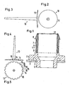
- the embodiment of the component according to Fig. 1 is a fluid line component in the form of a pipe socket with a tubular portion 1, which has a flange 2.
- the pipe socket is used to connect a fluid line in the form of a hose with another component, here the tank 3 of a motor vehicle. Of the tank 3, only part of its wall is shown with an opening 4, through which a lower End portion 5 of the pipe socket is passed with clearance.
- the tank 3 has substantially high density polyethylene (HDPE). Accordingly, the pipe socket on the outside on a material 6, which has the same thermoplastic material, here polyethylene (PE), which forms a fusion bond with the HDPE of the tank 3.
- PE polyethylene
- the flange 2 of the pipe socket is therefore welded by friction welding or by mirror welding to the tank 3.
- the hose is slid over a retaining rib 8 away and behind the retaining rib 8 by means of a tensioned clamp, such as a worm drive clamp clamped.
- a tensioned clamp such as a worm drive clamp clamped.
- the outer material has 6 PE, it alone is not sufficiently creep resistant. It could therefore under the clamping pressure of the clamp give way so far that the connection between the hose and pipe socket is leaking and the fuel - gasoline or diesel oil - escapes into the environment.
- a second thermoplastic material 9 has been injected into the end portion 7, which has a higher creep resistance.
- it has polyamide (PA), which may also be additionally reinforced, for example by glass fibers.
- Polyamide has the further advantage that it has a high diffusion barrier ability to hydrocarbons, such as gasoline or oil.
- the material 9 is injected at the free end of the end portion 7 in the material 6, as long as this after the Injection into the cavity of the mold has not yet fully cured. Since the curing begins on the cooler outer walls of the cavity of the mold, the inner part of the material 6 initially remains plastic. In this plastic "soul” then penetrates the molten material 9 during injection from the upper end of the end portion 7 ago, so that the material 6 receives a firmer core and is much thinner than the core. Depending on the choice of the ratio of the amounts or volumes of both materials 6 and 9, the total creep strength of the end portion 7, the diffusion barrierability to hydrocarbons and also the penetration depth of the material 9 into the material 6 can be determined.
- the material 9 it is sufficient to inject the material 9 only via the short end section 7, which is loaded by the clamp if the diffusion barrier capability is not desired or required over a relatively long section.
- the overall property of a desired part of the pipe socket or other fluid line component can therefore be targeted, localized set, so you can do with less expensive material 9, such as polyamide. If the glass fibers optionally contained in the material 9 are partially on the surface of the material 9, there is no risk that they are washed out by the gasoline or oil, because the material 9 is almost completely enveloped by the material 6.
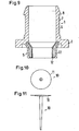
- the casting tool for the material 9 is shaped so that after the injection of the material 9 and the opening of the casting tool an approximately umbrella-like sprue 10 of the material 9, as shown in the FIGS. 2 and 3 in Top view or side view is shown, with the circumference of an approximately disc-shaped disc 11 after curing at the upper end of the pipe socket or end portion 7 remains formed.
- This sprue 10 is then cut from the pipe socket, so that thereafter at the upper end, here on the inside of the outer material 6, a continuously circumferential annular surface 12 of the material 9 remains, it can be seen that the material 9 via this annular surface 12 in the material 6 has been injected.
- the sprue piece 11 receives the inner (front) end of the injected material 9 a uniform circumferential shape, ie, the inner end is not wavy in the circumferential direction, but largely rectilinear limited, as indicated by the dashed line in FIG Fig. 1 is indicated.
- a sprue piece 13 is formed as shown in FIGS 4 and 5 is shown.
- the circumference of the disc-shaped disc 14 is provided with rectangular teeth 15 which are distributed uniformly over the circumference of the disc 14 and the Lükken 16 are as wide in the circumferential direction as the teeth 15th
- the teeth 15 correspond to outlet openings in the casting tool, via which the material 9 has been injected into the still plastic core of the material 6. Accordingly, the remaining after cutting the disc 14 in the upper edge of the pipe socket annular surface 12 consists of smaller ring surface sections, which alternately consist of the materials 6 and 9 and whose width corresponds in each case to the width of the teeth 15 and gaps 16 of the disk 14, as shown in FIG Fig. 8 is shown. Instead of a straight boundary line, as in Fig. 1 dashed lines, results in this case, a slightly wavy boundary line 21, as in Fig. 8 is shown schematically in the form of the dotted wavy line. Due to the Lükken 16 comes in comparison to the sprue 10 after the FIGS. 2 and 3 with slightly less material 9 for the casting 13 from. Also in the annular surface 12 less material 9 is present.
- a portion of the annular surface 12 lying between 40% and less than 100% consists of the same injected material 9 comprising polyamide, this part being equally spaced in the circumferential direction of the annular surface 12 at the upper end of the pipe socket Fig. 8 is distributed.
- the penetration depth is also determined by the ratio of the quantities or volumes of materials 6 and 9: the greater the amount of material 9 relative to that of material 6, the greater the penetration depth and vice versa.
- the number of teeth 15 and 19 and their width determines the one hand, the width of the annular surface portions of the material 9 in relation to the entire annular surface 12 and thus also the volume ratio of the materials 6 and 9 in the end portion 7 and the axial penetration depth of the material. 9 in the material 6, to use only as much of the expensive material 9 as is necessary, for example, to the total creep strength against that through the tensionable Clamp when clamping the hose on the end portion 7 to increase pressure exerted.
- Other overall properties of the end portion 7 can also be determined by the choice of the volume or volume ratio of the materials 6 and 9, for example the diffusion barrier capability or impermeability to hydrocarbons.
- the overall properties of the pipe socket can be determined locally according to the choice of the volume or volume ratios mentioned and depending on the choice of the position of the annular surface 12 and the formation of the casting tool and sprue.
- the end portion 7 need not have a higher creep strength than the material 6, if only a fluid line made of a plastic to be pushed onto the end portion 7, which holds itself on the end portion 7.
- end-side continuously annular surface 12 may also be an annular surface 12 according to Fig. 8 be provided at the lower end of the pipe section, in which the injected material, here the material 22, is distributed at regular intervals over the end-side annular surface, wherein the injected material 22 also at least 40% of the total, consisting of the two materials 6 and 22 annular surface 12 amounts to.
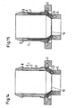
- Fig. 12 is again the same material 9, as in the embodiments of the Fig. 1 and 8th has been used, namely polyamide with glass fiber reinforcement, in the section 1, ie in both end sections 5 and 7 and additionally injected into the flange 2.
- the annular surface 12 is located here within the end portion 5, to whose formation in turn an injection tool has been used, in which the in the 10 and 11 shown sprue piece 10 results.
- the material 9 extends into both end portions 5 and 7 and the flange 2, on the one hand both end portions 5 and 7 and the flange 2 largely impermeable to hydrocarbons and on the other hand form the end portion 7 in the most pressure-loaded part of the end portion 7 as possible creep.
- a third material 23 made of plastic has been injected into the material 9 via the annular surface 12 in the transition region between the end portions 5 and 7.
- the material 23 contains the same plastic as the material 6, ie polyethylene (PE).
- PE polyethylene
- the polyethylene covers the glass fiber reinforced material 9 over its entire surface. This ensures that the glass fibers of the material 9 can not be washed out on the annular surface 12 by hydrocarbon-containing fluids, such as gasoline or oil, which flow through the pipe socket.
- the material 23 may also be an elastomer if the transition region between the end sections 5 and 7 is to be as flexible as possible. At the same time, part of the more expensive polyamide contained in the material 9 is saved.
- Fig. 15 The embodiment not covered by the scope of claim 1 Fig. 15 is different from that Fig. 14 only in that the material 23 extends further into the end portion 7 and slightly further into the flange 2, to increase the flexibility of the end portion 7 when using an elastomer material 23 and a little more costly, contained in the material 9 To save polyamide.
- the inner or embedded material may be selected from the group comprising PE, PP, reinforced PP, PBT, PET, EVOH, PBN, PEN, POM, PPS and fluorothermoplastic.
- the outer material 6 may alternatively be selected from the group comprising polyolefin, thermoplastic elastomer, unreinforced PA, thermoplastic polyester, and thermoplastic polyester elastomer.
Description
Die Erfindung bezieht sich auf ein Bauteil mit rohrförmigem Abschnitt, insbesondere Fluidleitungs-Bauteil, das wenigstens zwei Materialien mit unterschiedlicher Steifigkeit und/oder Kriechfestigkeit aufweist, wobei die Materialien thermoplastische Kunststoffe aufweisen und das steifere und/oder kriechfestere Material in dem anderen Material eingebettet ist.The invention relates to a component having a tubular section, in particular a fluid line component, which has at least two materials with different rigidity and / or creep resistance, the materials having thermoplastic materials and the stiffer and / or creep-resistant material being embedded in the other material.
Aus der
In
In
Der Erfindung liegt die Aufgabe zugrunde, ein Fluidleitungs-Bauteil der geschilderten Art anzugeben, bei dem die Verbindung der Kunststoffe fester und dichter ist und, soweit Versteifungsmaterial erforderlich ist, man mit weniger Versteifungsmaterial auskommt.The invention has for its object to provide a fluid line component of the kind described, in which the compound of the plastics is firmer and denser and, as far as stiffening material is required, one can do with less stiffening material.
Erfindungsgemäß ist diese Aufgabe dadurch gelöst, daß ein zwischen 40 % und weniger als 100 % liegender Teil der Ringfläche aus dem eingespritzten Material besteht und in gleichmäßigen Abständen in Umfangsrichtung der Ringfläche verteilt ist.According to the invention, this object is achieved in that a between 40% and less than 100% lying part of the annular surface consists of the injected material and is distributed at equal intervals in the circumferential direction of the annular surface.
Eine kontinuierlich umlaufende Einspritz-Ringfläche hat gegenüber einer nahezu punktförmigen Einspritzstelle den Vorteil, daß das eingespritzte Material gleichmäßig über dem gesamten Umfangsbereich des rohrförmigen Abschnitts verteilt und auch gleichmäßig weit, ohne eine Welligkeit am vorderen, inneren Ende, eingespritzt wird. Annähernd das gleiche, bis auf eine geringfügige Welligkeit am vorderen Ende, wird durch die Ausgestaltung nach Anspruch 1 erreicht, daß ein zwischen 40 % und weniger als 100 % liegender Teil der Ringfläche aus dem eingespritzten Material besteht und in gleichmäßigen Abständen in Umfangsrichtung der Ringfläche verteilt ist. Hierbei ergibt sich zwar eine geringfügige Welligkeit am inneren Ende des eingespritzten Materials, jedoch ist etwas weniger inneres Material in der Ringfläche und in einem beim Einspritzen entstehenden Angußteil erforderlich, was insbesondere dann von Vorteil ist, wenn das innere Material aus kostspieligerem Material, z.B. Polyamid, als das äußere Material, z.B. Polyethylen, besteht. Ferner kann bei dieser Lösung durch entsprechende Wahl des Mengenverhältnisses der beiden Materialien die Gesamtsteifigkeit, Kriechfestigkeit und/oder Impermeabilität des rohrförmigen Abschnitts gegenüber ein Hindurchdiffundieren von Kohlenwasserstoffen, wie Kraftfahrzeug-Kraftstoff, Öl oder alkoholhaltiges Kühlwasser, örtlich unterschiedlich oder so eingestellt werden, daß die unerwünschten Eigenschaften beider Materialien minimiert sind. Wenn z.B. eine Schelle zum Festklemmen einer flexiblen Fluidleitung, z.B. eines Schlauches, auf dem Fluidleitungs-Bauteil benutzt werden soll, dann braucht nur der durch die Schelle druckbelastete Bereich durch Einspritzen eines höher belastbaren oder verstärkten Kunststoffs in den entsprechenden Bereich der noch plastischen Seele des äußeren Materials (Kunststoffs) verstärkt zu werden. Prinzipiell können die Eigenschaften des Fluidleitungs-Bauteils durch unterschiedliche Positionierung der Ringfläche örtlich unterschiedlich gewählt werden. Wenn z.B. nur ein bestimmter Bereich des Fluidleitungs-Bauteils gegenüber Kohlenwasserstoffen impermeabel zu sein braucht, kann ein weitgehend impermeabler Kunststoff in diesen Bereich des äußeren Kunststoffs eingespritzt werden.A continuous circumferential injection annular surface has the advantage over a nearly punctiform injection point that the injected material is uniformly distributed over the entire peripheral region of the tubular portion and also uniformly far, without a ripple at the front, inner end, is injected. Almost the same, except for a slight waviness at the front end, is achieved by the embodiment according to
So kann dafür gesorgt sein, daß die Ringfläche durch in den inneren Kunststoff über die Ringfläche nachgespritzten Kunststoff, der dem äußeren Kunststoff gleicht, abgedeckt ist.So it can be ensured that the annular surface is covered by in the inner plastic over the ring surface nachgespritzten plastic, which is similar to the outer plastic.
Vorzugsweise kann dafür gesorgt sein, daß das Mengenverhältnis des eingebetteten Materials zum äußeren Material im Bereich von 10 % bis 90 % liegt.It may preferably be ensured that the ratio of the amount of the embedded material to the outer material is in the range of 10% to 90%.
Das eingebettete Material kann aus der Gruppe ausgewählt sein, die Polyamid (PA), verstärktes Polyamid, Polyethylen (PE), verstärktes Polyethylen, Polypropylen (PP), verstärktes Polypropylen, Polyethylenterephthalat (PET), Ethylenvinylalkohol (EVOH), Polybutylennaphthalat (PBN), Polyethylennaphthalat (PEN), Polyoximethylen (POM), Polyphenylensulfid (PPS) und Fluorthermoplast aufweist.The embedded material may be selected from the group consisting of polyamide (PA), reinforced polyamide, polyethylene (PE), reinforced polyethylene, polypropylene (PP), reinforced polypropylene, polyethylene terephthalate (PET), ethylene vinyl alcohol (EVOH), polybutylene naphthalate (PBN), Polyethylene naphthalate (PEN), polyoxymethylene (POM), polyphenylene sulfide (PPS) and fluorothermoplastic.
Ferner kann das äußere Material aus der Gruppe ausgewählt sein, die Polyolefin, thermoplastisches Elastomer, unverstärktes Polyamid, thermoplastisches Polyester und thermoplastisches Polyesterelastomer aufweist.Further, the outer material may be selected from the group consisting of polyolefin, thermoplastic elastomer, unreinforced polyamide, thermoplastic polyester and thermoplastic polyester elastomer.
Die Erfindung und ihre Weiterbildungen werden nachstehend anhand der beiliegenden Zeichnungen bevorzugter Ausführungsbeispiele näher beschrieben. Darin stellen dar:
- Fig. 1
- einen Axialschnitt eines nicht unter den Schutzbereich von
Anspruch 1 fallenden Ausführungsbeispiels des erfindungsgemäßen Bauteils, das auf dem Rand einer Öffnung eines Kraftfahrzeugtanks angeschweißt wird, - Fig. 2
- eine Draufsicht eines Angußstücks, das sich bei Verwendung eines entsprechenden Angußwerkzeugs beim Einspritzen eines Kunststoffs in die noch plastische Seele eines äußeren Kunststoffs des Bauteils ergibt, der zuerst gespritzt wurde,
- Fig. 3
- eine Seitenansicht des Angußstücks nach
Fig. 2 , - Fig. 4
- eine Seitenansicht eines Angußstücks nach
Anspruch 1 , das sich beim Einspritzen eines Kunststoffs in die noch plastische Seele des äußeren Kunststoffs des Bauteils nachFig. 1 ergibt, - Fig. 5
- eine Draufsicht des Angußstücks nach
Fig. 4 , - Fig. 6
- eine Seitenansicht einer Abwandlung des Angußstücks nach den
Fig. 4 und 5 , - Fig. 7
- eine Draufsicht des Angußstücks nach
Fig. 6 , - Fig. 8
- einen Axialschnitt eines weiteren Ausführungsbeispiels der Erfindung, bei dem sich das Angußstück nach den
Fig. 6 und 7 ergab, - Fig. 9
- einen Axialschnitt eines nicht unter den Schutzbereich von
Anspruch 1 fallenden Ausführungsbeispiels , - Fig. 10
- eine Draufsicht eines Angußstücks, das sich bei Verwendung eines entsprechenden Angußwerkzeugs ergibt, jedoch einen etwas kleineren Durchmesser als das Angußstück nach den
Fig. 2 und 3 hat, - Fig. 11
- eine Seitenansicht des Angußstücks nach
Fig. 10 , - Fig. 12
- einen Axialschnitt eines nicht unter den Schutzbereich von
Anspruch 1 fallenden Ausführungsbeispiels , - Fig. 13
- einen Axialschnitt eines nicht unter den Schutzbereich von
Anspruch 1 fallenden Ausführungsbeispiels , - Fig. 14
- einen Axialschnitt eines nicht unter den Schutzbereich von
Anspruch 1 fallenden Ausführungsbeispiels und - Fig. 15
- einen Axialschnitt eines nicht unter den Schutzbereich von
Anspruch 1 fallenden Ausführungsbeispiels .
- Fig. 1
- an axial section of a not falling under the scope of
claim 1 embodiment of the device according to the invention, which is welded to the edge of an opening of a motor vehicle tank, - Fig. 2
- a plan view of a sprue piece, which results in the use of a corresponding casting tool when injecting a plastic in the still plastic core of an outer plastic of the component, which was first injected,
- Fig. 3
- a side view of the sprue piece
Fig. 2 . - Fig. 4
- a side view of a sprue piece according to
claim 1, according to the injection of a plastic in the still plastic core of the outer plastic of the componentFig. 1 reveals - Fig. 5
- a plan view of the sprue piece
Fig. 4 . - Fig. 6
- a side view of a modification of the sprue piece after the
4 and 5 . - Fig. 7
- a plan view of the sprue piece
Fig. 6 . - Fig. 8
- an axial section of a further embodiment of the invention, in which the sprue piece after the
6 and 7 revealed - Fig. 9
- an axial section of a not falling under the scope of
claim 1 embodiment, - Fig. 10
- a plan view of a sprue piece, which results when using a corresponding casting tool, but a slightly smaller diameter than the sprue piece according to the
FIGS. 2 and 3 Has, - Fig. 11
- a side view of the sprue piece
Fig. 10 . - Fig. 12
- an axial section of a not falling under the scope of
claim 1 embodiment, - Fig. 13
- an axial section of a not falling under the scope of
claim 1 embodiment, - Fig. 14
- an axial section of a not falling under the scope of
claim 1 embodiment and - Fig. 15
- an axial section of a not falling under the scope of
claim 1 embodiment.
Das Ausführungsbeispiel des Bauteils nach
Der Tank 3 weist im wesentlichen hochdichtes Polyethylen (HDPE) auf. Dementsprechend weist auch der Rohrstutzen außen ein Material 6 auf, das denselben thermoplastischen Kunststoff aufweist, hier Polyethylen (PE), der mit dem HDPE des Tanks 3 eine Schmelzverbindung eingeht. Der Flansch 2 des Rohrstutzens wird daher im Reibschweißverfahren oder durch Spiegelschweißen mit dem Tank 3 verschweißt.The
Über den (in
Das Material 9 wird am freien Ende des Endabschnitts 7 in das Material 6 eingespritzt, solange dieses nach dem Einspritzen in die Kavität des Formwerkzeugs noch nicht vollständig ausgehärtet ist. Da das Aushärten an den kühleren Außenwänden der Kavität des Formwerkzeugs beginnt, bleibt der innere Teil des Materials 6 zunächst noch plastisch. In diese plastische "Seele" dringt dann das geschmolzene Material 9 beim Einspritzen vom oberen Ende des Endabschnitts 7 her ein, so daß das Material 6 einen festeren Kern erhält und wesentlich dünner als der Kern wird. Je nach Wahl des Verhältnisses der Mengen oder Volumina beider Materialien 6 und 9, kann die Gesamtkriechfestigkeit des Endabschnitts 7, dessen Diffusionssperrfähigkeit gegenüber Kohlenwasserstoffen und auch die Eindringtiefe des Materials 9 in das Material 6 bestimmt werden. So genügt es im vorliegenden Beispiel, das Material 9 nur über den kurzen Endabschnitt 7 einzuspritzen, der durch die Schelle belastet wird, wenn die Diffusionssperrfähigkeit nicht über einen längeren Abschnitt erwünscht oder erforderlich ist. Die Gesamteigenschaft eines gewünschten Teils des Rohrstutzens oder eines anderen Fluidleitungs-Bauteils kann daher gezielt, örtlich begrenzt eingestellt werden, so daß man mit weniger kostspieligem Material 9, wie Polyamid, auskommt. Wenn die im Material 9 gegebenenfalls enthaltenen Glasfasern teilweise an der Oberfläche des Materials 9 liegen, besteht nicht die Gefahr, daß sie durch das Benzin oder Öl ausgewaschen werden, weil das Material 9 nahezu vollständig vom Material 6 umhüllt ist.The
Das Angußwerkzeug für das Material 9 ist so geformt, daß nach dem Einspritzen des Materials 9 und dem Öffnen des Angußwerkzeugs ein etwa schirmartiges Angußstück 10 aus dem Material 9, wie es in den
Bei dieser Ausbildung des Angußstücks 11 erhält das innere (vordere) Ende des eingespritzten Materials 9 eine gleichmäßig umlaufende Form, d.h. das innere Ende ist nicht in Umfangsrichtung gewellt, sondern weitgehend geradlinig begrenzt, wie es durch die gestrichelte Linie in
Erfindungsgemäß ist ein Angußstück 13 ausgebildet , wie es in den
Die Zähne 15 entsprechen Austrittsöffnungen im Angußwerkzeug, über die das Material 9 in die noch plastische Seele des Materials 6 eingespritzt worden ist. Dementsprechend besteht die nach dem Abschneiden der Scheibe 14 im oberen Rand des Rohrstutzens verbleibende Ringfläche 12 aus kleineren Ringflächen-Abschnitten, die abwechselnd aus den Materialien 6 und 9 bestehen und deren Breite jeweils der Breite der Zähne 15 und Lücken 16 der Scheibe 14 entspricht, wie es in
Ein zwischen 40 % und weniger als 100 % liegender Teil der Ringfläche 12 besteht aus demselben eingespritzten Material 9, das Polyamid aufweist, wobei dieser Teil in gleichmäßigen Abständen in Umfangsrichtung der Ringfläche 12 am oberen Ende des Rohrstutzens nach
Die in den
Durch Änderung des Verhältnisses der Breite der Zähne 15 bzw. 19 zur Breite der zwischen ihnen liegenden Lükken 16 bzw. 20, kann ferner die Strömungsgeschwindigkeit des pro Hub eines das Material 9 aus dem Angußwerkzeug herausdrückenden Kolbens und damit die axiale Eindringtiefe des Materials 9 in die noch plastische Seele des Materials 6 bestimmt werden.By changing the ratio of the width of the
Die Eindringtiefe wird auch durch das Verhältnis der Mengen oder Volumina der Materialien 6 und 9 bestimmt: Je größer die Menge des Materials 9 im Verhältnis zu der des Materials 6 ist, um so größer ist die Eindringtiefe und umgekehrt. Außerdem ist in der Kavität des Formwerkzeugs hinreichend Ausweichraum für die durch das Material 9 verdrängte Menge des äußeren Materials 6 freigehalten. Auch die Anzahl der Zähne 15 bzw. 19 und ihre Breite bestimmt einerseits die Breite der Ringflächen-Abschnitte aus dem Material 9 im Verhältnis zur gesamten Ringfläche 12 und damit ebenfalls das Volumenverhältnis der Materialien 6 und 9 im Endabschnitt 7 und die axiale Eindringtiefe des Materials 9 im Material 6, um nur so viel des kostspieligen Materials 9 zu verwenden, wie es erforderlich ist, beispielsweise um die Gesamtkriechfestigkeit gegen den durch die spannbare Schelle beim Festklemmen des Schlauches auf dem Endabschnitt 7 ausgeübten Druck zu erhöhen. Auch andere Gesamteigenschaften des Endabschnitts 7 lassen sich durch die Wahl des Volumen- oder Mengenverhältnisses der Materialien 6 und 9 festlegen, beispielsweise die Diffusionssperrfähigkeit oder Impermeabilität gegenüber Kohlenwasserstoffen.The penetration depth is also determined by the ratio of the quantities or volumes of
Desgleichen lassen sich die Gesamteigenschaften des Rohrstutzens örtlich entsprechend der Wahl der erwähnten Volumen- oder Mengenverhältnisse und in Abhängigkeit von der Wahl der Lage der Ringfläche 12 und der Ausbildung des Angußwerkzeugs und Angußstücks vorherbestimmen.Likewise, the overall properties of the pipe socket can be determined locally according to the choice of the volume or volume ratios mentioned and depending on the choice of the position of the
So ist bei dem nicht unter den Schutzbereich von Anspruch 1 fallenden Ausführungsbeispiel des ebenfalls als Rohrstutzen ausgebildeten Bauteils nach
Statt der endseitig kontinuierlich umlaufenden Ringfläche 12 kann auch eine Ringfläche 12 gemäß
Bei dem nicht unter den Schutzbereich von Anspruch 1 fallenden Ausführungsbeispiel nach
Das nicht unter den Schutzbereich von Anspruch 1 fallenden Ausführungsbeispiel nach
Das nicht unter den Schutzbereich von Anspruch 1 fallenden Ausführungsbeispiel nach
Das nicht unter den Schutzbereich von Anspruch 1 fallenden Ausführungsbeispiel nach
Anstelle des erwähnten Materials PE und des glasfaserverstärkten PA kann das innere bzw. eingebettete Material aus der Gruppe ausgewählt sein, die PE, PP, verstärktes PP, PBT, PET, EVOH, PBN, PEN, POM, PPS und Fluorthermoplast aufweist. Das äußere Material 6 kann alternativ aus der Gruppe ausgewählt sein, die Polyolefin, thermoplastisches Elastomer, unverstärktes PA, thermoplastisches Polyester und thermoplastisches Polyesterelastomer aufweist.Instead of the mentioned material PE and the glass fiber reinforced PA, the inner or embedded material may be selected from the group comprising PE, PP, reinforced PP, PBT, PET, EVOH, PBN, PEN, POM, PPS and fluorothermoplastic. The
Claims (5)
- Part with tubular section (1), particularly a fluid line structural component, comprising at least two materials having different stiffness and/or creeping strength, whereas the materials comprise thermoplastic synthetic materials (6,9,22,23) and the material (9) having a greater stiffness and/or creeping strength is embedded in the other material (6), whereas the tubular section (1) comprises an annular surface (12) revolving coaxially to the longitudinal center axis of the structural component across which the material having a greater stiffness and/or creeping strength has been injected, characterized in that a between 40% and less than 100% located part of the annular surface (12) is composed of the injected material and is distributed in uniform spacings in circumferential direction of the annular surface (12).
- Part according to claim 1, characterized in that the annular surface (12) is covered by a synthetic material (23) injected subsequently into the inner synthetic material (9) over the annular surface (12) which equals the outer synthetic material (6).
- Part according to claim 1 or 2, characterized in that the quantity ratio of the embedded material (9; 22; 23) to the outer material (6) is in the range of 10% to 90%.
- Part according to one of the claims 1 to 3, characterized in that the embedded material (9;22;23) is selected from the group, which comprises polyamide (PA), reinforced polyamide, polyethylene (PE), reinforced polyethylene, polypropylene (PP), reinforced polypropylene, polyethylene terephthalate (PET), ethylene vinyl alcohol (EVOH), polybutylene naphthalate (PBN), polyethylene naphthalate (PEN), polyoximethylene (POM), polyphenylene sulfide (PPS), and fluorothermoplastic material.
- Part according to one of the claims 1 to 4, characterized in that the outer material is selected from the group, which comprises polyolefin, thermoplastic elastomer, non-reinforced polyamide, thermoplastic polyester, and thermoplastic polyester elastomer.
Applications Claiming Priority (1)
| Application Number | Priority Date | Filing Date | Title |
|---|---|---|---|
| DE102004042847A DE102004042847A1 (en) | 2004-09-04 | 2004-09-04 | Component with tubular section |
Publications (3)
| Publication Number | Publication Date |
|---|---|
| EP1632380A2 EP1632380A2 (en) | 2006-03-08 |
| EP1632380A3 EP1632380A3 (en) | 2007-02-14 |
| EP1632380B1 true EP1632380B1 (en) | 2009-07-01 |
Family
ID=35432639
Family Applications (1)
| Application Number | Title | Priority Date | Filing Date |
|---|---|---|---|
| EP05016822A Expired - Fee Related EP1632380B1 (en) | 2004-09-04 | 2005-08-03 | Part with tubular section |
Country Status (5)
| Country | Link |
|---|---|
| US (1) | US8394472B2 (en) |
| EP (1) | EP1632380B1 (en) |
| JP (1) | JP4508047B2 (en) |
| CN (1) | CN1749630A (en) |
| DE (2) | DE102004042847A1 (en) |
Families Citing this family (7)
| Publication number | Priority date | Publication date | Assignee | Title |
|---|---|---|---|---|
| DE202009016927U1 (en) * | 2009-12-15 | 2010-04-29 | Feichtinger, Reinhard | Fuel attachment |
| AT511645B1 (en) | 2011-07-05 | 2015-05-15 | Praher Kunststofftechnik Gmbh | SANDWICH INJECTION MOLDING AND FORMING COMPRISING A LAYERED COMPOSITE PRODUCED BY THE SANDWICH MOLDING METHOD |
| CA2877961C (en) * | 2012-07-02 | 2019-09-24 | Norma U.S. Holding Llc | Fuel line connector and method of making |
| DE102014215444A1 (en) | 2014-08-05 | 2016-02-11 | Mahle International Gmbh | Device for laser structuring of hubs of engine components |
| CN113653878A (en) * | 2016-06-03 | 2021-11-16 | 亚普汽车部件股份有限公司 | Blow needle component matched with joint component and hollow box body forming method provided with blow needle component |
| US10883640B2 (en) | 2016-06-24 | 2021-01-05 | Eaton Intelligent Power Limited | Fluid couplings, systems, and methods |
| US11149883B2 (en) | 2016-06-24 | 2021-10-19 | Eaton Intelligent Power Limited | Fluid couplings, systems, and methods |
Family Cites Families (8)
| Publication number | Priority date | Publication date | Assignee | Title |
|---|---|---|---|---|
| JPS51121070A (en) * | 1975-04-15 | 1976-10-22 | Sumitomo Chemical Co | Improved sandwich molding method and metallic mold |
| DE4239909C1 (en) | 1992-11-27 | 1994-05-05 | Rasmussen Gmbh | Tubular plastic connector for flexible lines - comprises fibre reinforced first part with low creep, injected onto unreinforced second part |
| DE19617349C1 (en) * | 1996-04-30 | 1997-09-04 | Hans Kuehn | Injection moulding of multilayered tubing |
| DE19953746C2 (en) * | 1999-06-21 | 2001-10-04 | Rasmussen Gmbh | Method of making a nozzle |
| DE10048973A1 (en) * | 1999-09-27 | 2001-07-05 | Heiner Becker | Plastic pipe fitting, e.g. for welded and mechanical joints at opposite ends, comprises a single two component injection molding |
| DE20022716U1 (en) * | 2000-12-16 | 2002-02-28 | Rasmussen Gmbh | Tubular nozzle |
| JP2003300542A (en) * | 2002-04-10 | 2003-10-21 | Sekisui Chem Co Ltd | Stopper for airtight container |
| DE10241286B4 (en) * | 2002-09-03 | 2004-07-22 | Rasmussen Gmbh | Component for connecting a fluid conduit with an opening of a plastic-containing container or for closing the opening |
-
2004
- 2004-09-04 DE DE102004042847A patent/DE102004042847A1/en not_active Withdrawn
-
2005
- 2005-08-03 DE DE502005007606T patent/DE502005007606D1/en active Active
- 2005-08-03 EP EP05016822A patent/EP1632380B1/en not_active Expired - Fee Related
- 2005-09-01 US US11/217,222 patent/US8394472B2/en active Active
- 2005-09-02 JP JP2005254737A patent/JP4508047B2/en active Active
- 2005-09-05 CN CNA2005101036482A patent/CN1749630A/en active Pending
Also Published As
| Publication number | Publication date |
|---|---|
| US20060051548A1 (en) | 2006-03-09 |
| JP4508047B2 (en) | 2010-07-21 |
| CN1749630A (en) | 2006-03-22 |
| DE102004042847A1 (en) | 2006-03-09 |
| DE502005007606D1 (en) | 2009-08-13 |
| EP1632380A2 (en) | 2006-03-08 |
| EP1632380A3 (en) | 2007-02-14 |
| US8394472B2 (en) | 2013-03-12 |
| JP2006069210A (en) | 2006-03-16 |
Similar Documents
| Publication | Publication Date | Title |
|---|---|---|
| EP1632380B1 (en) | Part with tubular section | |
| EP1396326B1 (en) | Connector between a fluid conduit and the opening of a resin container | |
| EP1674232B1 (en) | Process for making a branch stub | |
| DE19641751B4 (en) | Two-part connecting element | |
| DE69821212T2 (en) | Hollow resin container | |
| DE102008009418B3 (en) | cap | |
| EP1323973A2 (en) | Fluid or steam conveying system with a weld seam made from a coextruded laminate | |
| WO2014049097A1 (en) | Prefilled syringe | |
| EP0619176B1 (en) | Process for welding thermoplastic pipes | |
| EP3490776B1 (en) | Method for producing a liquid container, liquid container for a motor vehicle and injection molding tool | |
| DE19953746C2 (en) | Method of making a nozzle | |
| DE102013004929A1 (en) | The working fluid container | |
| EP0728937B1 (en) | Fuel feeding device | |
| EP1396327B1 (en) | Fitting for the connection of a fuel tank with a fluid conduit and process for its manufacture | |
| EP3676080A1 (en) | Liquid container and method for producing a liquid container | |
| DE10324471B3 (en) | Pipe-like neck | |
| EP1989030B1 (en) | Mixing head with creep barrier on the cleaning piston | |
| DE10056974C1 (en) | Tubular pouring spout for a petrol or diesel oil container made from thermoplastic, especially polyethylene, has tubular section made from plastic with low swelling properties and ring with conical cross-section which fits around it | |
| DE102011011215A1 (en) | Method for positively connecting two workpieces together, involves filling region of injection channel with plug after withdrawing injection tool, so that one of workpieces is welded to another workpiece | |
| EP3178644B1 (en) | Multi-component plastic body | |
| DE102006010141A1 (en) | Hydraulic clutch actuation system, has sliding contact surface or outer peripheral surface made of different plastic material than material of plastic cylinder housing part and plastic component | |
| DE10062997A1 (en) | Tubular connector piece for attachment to opening of container comprises first and second parts made of materials capable of chemically combining across their contact surfaces | |
| DE3437659A1 (en) | HOSE, ESPECIALLY FOR MOTOR VEHICLES | |
| DE3413632C2 (en) | ||
| DE102016013090A1 (en) | filter cartridge |
Legal Events
| Date | Code | Title | Description |
|---|---|---|---|
| PUAI | Public reference made under article 153(3) epc to a published international application that has entered the european phase |
Free format text: ORIGINAL CODE: 0009012 |
|
| AK | Designated contracting states |
Kind code of ref document: A2 Designated state(s): AT BE BG CH CY CZ DE DK EE ES FI FR GB GR HU IE IS IT LI LT LU LV MC NL PL PT RO SE SI SK TR |
|
| AX | Request for extension of the european patent |
Extension state: AL BA HR MK YU |
|
| PUAL | Search report despatched |
Free format text: ORIGINAL CODE: 0009013 |
|
| AK | Designated contracting states |
Kind code of ref document: A3 Designated state(s): AT BE BG CH CY CZ DE DK EE ES FI FR GB GR HU IE IS IT LI LT LU LV MC NL PL PT RO SE SI SK TR |
|
| AX | Request for extension of the european patent |
Extension state: AL BA HR MK YU |
|
| 17P | Request for examination filed |
Effective date: 20070306 |
|
| 17Q | First examination report despatched |
Effective date: 20070404 |
|
| RAP1 | Party data changed (applicant data changed or rights of an application transferred) |
Owner name: NORMA GERMANY GMBH |
|
| AKX | Designation fees paid |
Designated state(s): DE ES FR GB IT |
|
| GRAP | Despatch of communication of intention to grant a patent |
Free format text: ORIGINAL CODE: EPIDOSNIGR1 |
|
| GRAS | Grant fee paid |
Free format text: ORIGINAL CODE: EPIDOSNIGR3 |
|
| GRAA | (expected) grant |
Free format text: ORIGINAL CODE: 0009210 |
|
| AK | Designated contracting states |
Kind code of ref document: B1 Designated state(s): DE ES FR GB IT |
|
| REG | Reference to a national code |
Ref country code: GB Ref legal event code: FG4D Free format text: NOT ENGLISH |
|
| REF | Corresponds to: |
Ref document number: 502005007606 Country of ref document: DE Date of ref document: 20090813 Kind code of ref document: P |
|
| PG25 | Lapsed in a contracting state [announced via postgrant information from national office to epo] |
Ref country code: ES Free format text: LAPSE BECAUSE OF FAILURE TO SUBMIT A TRANSLATION OF THE DESCRIPTION OR TO PAY THE FEE WITHIN THE PRESCRIBED TIME-LIMIT Effective date: 20091012 |
|
| PLBE | No opposition filed within time limit |
Free format text: ORIGINAL CODE: 0009261 |
|
| STAA | Information on the status of an ep patent application or granted ep patent |
Free format text: STATUS: NO OPPOSITION FILED WITHIN TIME LIMIT |
|
| 26N | No opposition filed |
Effective date: 20100406 |
|
| PG25 | Lapsed in a contracting state [announced via postgrant information from national office to epo] |
Ref country code: GB Free format text: LAPSE BECAUSE OF NON-PAYMENT OF DUE FEES Effective date: 20091001 |
|
| PGFP | Annual fee paid to national office [announced via postgrant information from national office to epo] |
Ref country code: IT Payment date: 20130823 Year of fee payment: 9 |
|
| PGFP | Annual fee paid to national office [announced via postgrant information from national office to epo] |
Ref country code: DE Payment date: 20140816 Year of fee payment: 10 |
|
| PGFP | Annual fee paid to national office [announced via postgrant information from national office to epo] |
Ref country code: FR Payment date: 20140819 Year of fee payment: 10 |
|
| REG | Reference to a national code |
Ref country code: DE Ref legal event code: R082 Ref document number: 502005007606 Country of ref document: DE Representative=s name: PATENTANWAELTE OLBRICHT, BUCHHOLD, KEULERTZ PA, DE |
|
| PG25 | Lapsed in a contracting state [announced via postgrant information from national office to epo] |
Ref country code: IT Free format text: LAPSE BECAUSE OF NON-PAYMENT OF DUE FEES Effective date: 20140803 |
|
| REG | Reference to a national code |
Ref country code: DE Ref legal event code: R119 Ref document number: 502005007606 Country of ref document: DE |
|
| REG | Reference to a national code |
Ref country code: FR Ref legal event code: ST Effective date: 20160429 |
|
| PG25 | Lapsed in a contracting state [announced via postgrant information from national office to epo] |
Ref country code: DE Free format text: LAPSE BECAUSE OF NON-PAYMENT OF DUE FEES Effective date: 20160301 |
|
| PG25 | Lapsed in a contracting state [announced via postgrant information from national office to epo] |
Ref country code: FR Free format text: LAPSE BECAUSE OF NON-PAYMENT OF DUE FEES Effective date: 20150831 |