EP1394884A2 - Electrolyte membrane for fuel cell operable in medium temperature range, fuel cell using the same, and manufacturing methods therefor - Google Patents
Electrolyte membrane for fuel cell operable in medium temperature range, fuel cell using the same, and manufacturing methods therefor Download PDFInfo
- Publication number
- EP1394884A2 EP1394884A2 EP03019390A EP03019390A EP1394884A2 EP 1394884 A2 EP1394884 A2 EP 1394884A2 EP 03019390 A EP03019390 A EP 03019390A EP 03019390 A EP03019390 A EP 03019390A EP 1394884 A2 EP1394884 A2 EP 1394884A2
- Authority
- EP
- European Patent Office
- Prior art keywords
- electrolyte
- electrolyte membrane
- layer
- fuel cell
- hydrogen
- Prior art date
- Legal status (The legal status is an assumption and is not a legal conclusion. Google has not performed a legal analysis and makes no representation as to the accuracy of the status listed.)
- Granted
Links
- 239000003792 electrolyte Substances 0.000 title claims abstract description 225
- 239000000446 fuel Substances 0.000 title claims abstract description 126
- 239000012528 membrane Substances 0.000 title claims abstract description 119
- 238000004519 manufacturing process Methods 0.000 title claims description 22
- 229910052751 metal Inorganic materials 0.000 claims abstract description 101
- 239000002184 metal Substances 0.000 claims abstract description 101
- 239000001257 hydrogen Substances 0.000 claims abstract description 98
- 229910052739 hydrogen Inorganic materials 0.000 claims abstract description 98
- UFHFLCQGNIYNRP-UHFFFAOYSA-N Hydrogen Chemical compound [H][H] UFHFLCQGNIYNRP-UHFFFAOYSA-N 0.000 claims abstract description 92
- 239000000758 substrate Substances 0.000 claims abstract description 77
- 239000007787 solid Substances 0.000 claims abstract description 53
- 229920005597 polymer membrane Polymers 0.000 claims abstract description 24
- KDLHZDBZIXYQEI-UHFFFAOYSA-N Palladium Chemical compound [Pd] KDLHZDBZIXYQEI-UHFFFAOYSA-N 0.000 claims description 110
- 239000000463 material Substances 0.000 claims description 106
- 230000001629 suppression Effects 0.000 claims description 75
- 238000009792 diffusion process Methods 0.000 claims description 63
- QVGXLLKOCUKJST-UHFFFAOYSA-N atomic oxygen Chemical compound [O] QVGXLLKOCUKJST-UHFFFAOYSA-N 0.000 claims description 47
- 239000001301 oxygen Substances 0.000 claims description 47
- 229910052760 oxygen Inorganic materials 0.000 claims description 47
- 238000006243 chemical reaction Methods 0.000 claims description 39
- 229910052763 palladium Inorganic materials 0.000 claims description 39
- LEONUFNNVUYDNQ-UHFFFAOYSA-N vanadium atom Chemical compound [V] LEONUFNNVUYDNQ-UHFFFAOYSA-N 0.000 claims description 39
- 239000002131 composite material Substances 0.000 claims description 25
- 238000000576 coating method Methods 0.000 claims description 24
- 239000010955 niobium Substances 0.000 claims description 22
- 229910052720 vanadium Inorganic materials 0.000 claims description 20
- 229910052783 alkali metal Inorganic materials 0.000 claims description 19
- 239000004020 conductor Substances 0.000 claims description 19
- 150000001340 alkali metals Chemical class 0.000 claims description 18
- 229910052758 niobium Inorganic materials 0.000 claims description 18
- GUCVJGMIXFAOAE-UHFFFAOYSA-N niobium atom Chemical compound [Nb] GUCVJGMIXFAOAE-UHFFFAOYSA-N 0.000 claims description 18
- 229910052715 tantalum Inorganic materials 0.000 claims description 18
- GUVRBAGPIYLISA-UHFFFAOYSA-N tantalum atom Chemical compound [Ta] GUVRBAGPIYLISA-UHFFFAOYSA-N 0.000 claims description 18
- 239000007789 gas Substances 0.000 claims description 16
- 229910045601 alloy Inorganic materials 0.000 claims description 15
- 239000000956 alloy Substances 0.000 claims description 15
- 239000011248 coating agent Substances 0.000 claims description 15
- 239000002737 fuel gas Substances 0.000 claims description 15
- 239000000919 ceramic Substances 0.000 claims description 14
- 230000001590 oxidative effect Effects 0.000 claims description 14
- 239000011810 insulating material Substances 0.000 claims description 13
- 239000011533 mixed conductor Substances 0.000 claims description 12
- 238000000926 separation method Methods 0.000 claims description 10
- 150000002431 hydrogen Chemical class 0.000 claims description 6
- 229910001252 Pd alloy Inorganic materials 0.000 claims description 5
- 239000007769 metal material Substances 0.000 claims description 4
- 125000004430 oxygen atom Chemical group O* 0.000 claims description 2
- 230000002194 synthesizing effect Effects 0.000 claims 2
- 239000005518 polymer electrolyte Substances 0.000 abstract description 2
- 238000000034 method Methods 0.000 description 22
- 239000000470 constituent Substances 0.000 description 19
- 229910000272 alkali metal oxide Inorganic materials 0.000 description 18
- 230000035699 permeability Effects 0.000 description 16
- 230000008569 process Effects 0.000 description 11
- CURLTUGMZLYLDI-UHFFFAOYSA-N Carbon dioxide Chemical compound O=C=O CURLTUGMZLYLDI-UHFFFAOYSA-N 0.000 description 9
- 229910000990 Ni alloy Inorganic materials 0.000 description 9
- 150000002739 metals Chemical class 0.000 description 9
- HBVFXTAPOLSOPB-UHFFFAOYSA-N nickel vanadium Chemical compound [V].[Ni] HBVFXTAPOLSOPB-UHFFFAOYSA-N 0.000 description 9
- 230000009467 reduction Effects 0.000 description 9
- 239000003054 catalyst Substances 0.000 description 8
- 230000008901 benefit Effects 0.000 description 6
- 229910002092 carbon dioxide Inorganic materials 0.000 description 6
- 239000001569 carbon dioxide Substances 0.000 description 6
- 230000007423 decrease Effects 0.000 description 6
- 238000012986 modification Methods 0.000 description 6
- 230000004048 modification Effects 0.000 description 6
- BASFCYQUMIYNBI-UHFFFAOYSA-N platinum Chemical compound [Pt] BASFCYQUMIYNBI-UHFFFAOYSA-N 0.000 description 6
- 229920000557 Nafion® Polymers 0.000 description 5
- 238000005275 alloying Methods 0.000 description 5
- GWEVSGVZZGPLCZ-UHFFFAOYSA-N Titan oxide Chemical compound O=[Ti]=O GWEVSGVZZGPLCZ-UHFFFAOYSA-N 0.000 description 4
- -1 for example Polymers 0.000 description 4
- NUJOXMJBOLGQSY-UHFFFAOYSA-N manganese dioxide Chemical compound O=[Mn]=O NUJOXMJBOLGQSY-UHFFFAOYSA-N 0.000 description 4
- 239000007784 solid electrolyte Substances 0.000 description 4
- 229910052596 spinel Inorganic materials 0.000 description 4
- 239000011029 spinel Substances 0.000 description 4
- BVKZGUZCCUSVTD-UHFFFAOYSA-L Carbonate Chemical compound [O-]C([O-])=O BVKZGUZCCUSVTD-UHFFFAOYSA-L 0.000 description 3
- PXHVJJICTQNCMI-UHFFFAOYSA-N Nickel Chemical compound [Ni] PXHVJJICTQNCMI-UHFFFAOYSA-N 0.000 description 3
- 229910003408 SrCeO3 Inorganic materials 0.000 description 3
- PNEYBMLMFCGWSK-UHFFFAOYSA-N aluminium oxide Inorganic materials [O-2].[O-2].[O-2].[Al+3].[Al+3] PNEYBMLMFCGWSK-UHFFFAOYSA-N 0.000 description 3
- 229910052761 rare earth metal Inorganic materials 0.000 description 3
- 229910002761 BaCeO3 Inorganic materials 0.000 description 2
- 229910000873 Beta-alumina solid electrolyte Inorganic materials 0.000 description 2
- 229910052684 Cerium Inorganic materials 0.000 description 2
- VYPSYNLAJGMNEJ-UHFFFAOYSA-N Silicium dioxide Chemical compound O=[Si]=O VYPSYNLAJGMNEJ-UHFFFAOYSA-N 0.000 description 2
- 229910052769 Ytterbium Inorganic materials 0.000 description 2
- MCMNRKCIXSYSNV-UHFFFAOYSA-N Zirconium dioxide Chemical compound O=[Zr]=O MCMNRKCIXSYSNV-UHFFFAOYSA-N 0.000 description 2
- 239000010953 base metal Substances 0.000 description 2
- 230000015572 biosynthetic process Effects 0.000 description 2
- 230000015556 catabolic process Effects 0.000 description 2
- GWXLDORMOJMVQZ-UHFFFAOYSA-N cerium Chemical compound [Ce] GWXLDORMOJMVQZ-UHFFFAOYSA-N 0.000 description 2
- 230000008020 evaporation Effects 0.000 description 2
- 238000001704 evaporation Methods 0.000 description 2
- 239000011521 glass Substances 0.000 description 2
- 238000010438 heat treatment Methods 0.000 description 2
- 239000011964 heteropoly acid Substances 0.000 description 2
- 125000004435 hydrogen atom Chemical group [H]* 0.000 description 2
- 239000012535 impurity Substances 0.000 description 2
- 239000012212 insulator Substances 0.000 description 2
- JEIPFZHSYJVQDO-UHFFFAOYSA-N iron(III) oxide Inorganic materials O=[Fe]O[Fe]=O JEIPFZHSYJVQDO-UHFFFAOYSA-N 0.000 description 2
- 239000011572 manganese Substances 0.000 description 2
- 229910000473 manganese(VI) oxide Inorganic materials 0.000 description 2
- 229910044991 metal oxide Inorganic materials 0.000 description 2
- 150000004706 metal oxides Chemical class 0.000 description 2
- 229910052697 platinum Inorganic materials 0.000 description 2
- 238000010248 power generation Methods 0.000 description 2
- VSZWPYCFIRKVQL-UHFFFAOYSA-N selanylidenegallium;selenium Chemical compound [Se].[Se]=[Ga].[Se]=[Ga] VSZWPYCFIRKVQL-UHFFFAOYSA-N 0.000 description 2
- 239000010936 titanium Substances 0.000 description 2
- NAWDYIZEMPQZHO-UHFFFAOYSA-N ytterbium Chemical compound [Yb] NAWDYIZEMPQZHO-UHFFFAOYSA-N 0.000 description 2
- 229910052727 yttrium Inorganic materials 0.000 description 2
- VWQVUPCCIRVNHF-UHFFFAOYSA-N yttrium atom Chemical compound [Y] VWQVUPCCIRVNHF-UHFFFAOYSA-N 0.000 description 2
- OKTJSMMVPCPJKN-UHFFFAOYSA-N Carbon Chemical compound [C] OKTJSMMVPCPJKN-UHFFFAOYSA-N 0.000 description 1
- XEEYBQQBJWHFJM-UHFFFAOYSA-N Iron Chemical compound [Fe] XEEYBQQBJWHFJM-UHFFFAOYSA-N 0.000 description 1
- PWHULOQIROXLJO-UHFFFAOYSA-N Manganese Chemical compound [Mn] PWHULOQIROXLJO-UHFFFAOYSA-N 0.000 description 1
- RTAQQCXQSZGOHL-UHFFFAOYSA-N Titanium Chemical compound [Ti] RTAQQCXQSZGOHL-UHFFFAOYSA-N 0.000 description 1
- 229910000288 alkali metal carbonate Inorganic materials 0.000 description 1
- 150000008041 alkali metal carbonates Chemical class 0.000 description 1
- 229910052799 carbon Inorganic materials 0.000 description 1
- 150000004649 carbonic acid derivatives Chemical class 0.000 description 1
- 238000005234 chemical deposition Methods 0.000 description 1
- 229910052681 coesite Inorganic materials 0.000 description 1
- 229910052593 corundum Inorganic materials 0.000 description 1
- 229910052906 cristobalite Inorganic materials 0.000 description 1
- 230000003247 decreasing effect Effects 0.000 description 1
- 238000003487 electrochemical reaction Methods 0.000 description 1
- 229910010272 inorganic material Inorganic materials 0.000 description 1
- 239000011147 inorganic material Substances 0.000 description 1
- 150000002500 ions Chemical class 0.000 description 1
- CPLXHLVBOLITMK-UHFFFAOYSA-N magnesium oxide Inorganic materials [Mg]=O CPLXHLVBOLITMK-UHFFFAOYSA-N 0.000 description 1
- 230000014759 maintenance of location Effects 0.000 description 1
- 229910052748 manganese Inorganic materials 0.000 description 1
- 230000007246 mechanism Effects 0.000 description 1
- 229910052759 nickel Inorganic materials 0.000 description 1
- 238000005289 physical deposition Methods 0.000 description 1
- 239000011148 porous material Substances 0.000 description 1
- 230000000717 retained effect Effects 0.000 description 1
- 238000007789 sealing Methods 0.000 description 1
- 239000000377 silicon dioxide Substances 0.000 description 1
- 238000004544 sputter deposition Methods 0.000 description 1
- 229910052682 stishovite Inorganic materials 0.000 description 1
- 229910052719 titanium Inorganic materials 0.000 description 1
- 229910052905 tridymite Inorganic materials 0.000 description 1
- ZNOKGRXACCSDPY-UHFFFAOYSA-N tungsten trioxide Chemical compound O=[W](=O)=O ZNOKGRXACCSDPY-UHFFFAOYSA-N 0.000 description 1
- XLYOFNOQVPJJNP-UHFFFAOYSA-N water Substances O XLYOFNOQVPJJNP-UHFFFAOYSA-N 0.000 description 1
- 229910001845 yogo sapphire Inorganic materials 0.000 description 1
Images


Classifications
-
- H—ELECTRICITY
- H01—ELECTRIC ELEMENTS
- H01M—PROCESSES OR MEANS, e.g. BATTERIES, FOR THE DIRECT CONVERSION OF CHEMICAL ENERGY INTO ELECTRICAL ENERGY
- H01M8/00—Fuel cells; Manufacture thereof
- H01M8/10—Fuel cells with solid electrolytes
- H01M8/12—Fuel cells with solid electrolytes operating at high temperature, e.g. with stabilised ZrO2 electrolyte
- H01M8/124—Fuel cells with solid electrolytes operating at high temperature, e.g. with stabilised ZrO2 electrolyte characterised by the process of manufacturing or by the material of the electrolyte
-
- H—ELECTRICITY
- H01—ELECTRIC ELEMENTS
- H01M—PROCESSES OR MEANS, e.g. BATTERIES, FOR THE DIRECT CONVERSION OF CHEMICAL ENERGY INTO ELECTRICAL ENERGY
- H01M8/00—Fuel cells; Manufacture thereof
- H01M8/02—Details
- H01M8/0289—Means for holding the electrolyte
-
- H—ELECTRICITY
- H01—ELECTRIC ELEMENTS
- H01M—PROCESSES OR MEANS, e.g. BATTERIES, FOR THE DIRECT CONVERSION OF CHEMICAL ENERGY INTO ELECTRICAL ENERGY
- H01M8/00—Fuel cells; Manufacture thereof
- H01M8/10—Fuel cells with solid electrolytes
- H01M8/1004—Fuel cells with solid electrolytes characterised by membrane-electrode assemblies [MEA]
-
- H—ELECTRICITY
- H01—ELECTRIC ELEMENTS
- H01M—PROCESSES OR MEANS, e.g. BATTERIES, FOR THE DIRECT CONVERSION OF CHEMICAL ENERGY INTO ELECTRICAL ENERGY
- H01M8/00—Fuel cells; Manufacture thereof
- H01M8/10—Fuel cells with solid electrolytes
- H01M8/12—Fuel cells with solid electrolytes operating at high temperature, e.g. with stabilised ZrO2 electrolyte
- H01M8/1213—Fuel cells with solid electrolytes operating at high temperature, e.g. with stabilised ZrO2 electrolyte characterised by the electrode/electrolyte combination or the supporting material
-
- H—ELECTRICITY
- H01—ELECTRIC ELEMENTS
- H01M—PROCESSES OR MEANS, e.g. BATTERIES, FOR THE DIRECT CONVERSION OF CHEMICAL ENERGY INTO ELECTRICAL ENERGY
- H01M8/00—Fuel cells; Manufacture thereof
- H01M8/10—Fuel cells with solid electrolytes
- H01M8/1016—Fuel cells with solid electrolytes characterised by the electrolyte material
-
- Y—GENERAL TAGGING OF NEW TECHNOLOGICAL DEVELOPMENTS; GENERAL TAGGING OF CROSS-SECTIONAL TECHNOLOGIES SPANNING OVER SEVERAL SECTIONS OF THE IPC; TECHNICAL SUBJECTS COVERED BY FORMER USPC CROSS-REFERENCE ART COLLECTIONS [XRACs] AND DIGESTS
- Y02—TECHNOLOGIES OR APPLICATIONS FOR MITIGATION OR ADAPTATION AGAINST CLIMATE CHANGE
- Y02E—REDUCTION OF GREENHOUSE GAS [GHG] EMISSIONS, RELATED TO ENERGY GENERATION, TRANSMISSION OR DISTRIBUTION
- Y02E60/00—Enabling technologies; Technologies with a potential or indirect contribution to GHG emissions mitigation
- Y02E60/30—Hydrogen technology
- Y02E60/50—Fuel cells
-
- Y—GENERAL TAGGING OF NEW TECHNOLOGICAL DEVELOPMENTS; GENERAL TAGGING OF CROSS-SECTIONAL TECHNOLOGIES SPANNING OVER SEVERAL SECTIONS OF THE IPC; TECHNICAL SUBJECTS COVERED BY FORMER USPC CROSS-REFERENCE ART COLLECTIONS [XRACs] AND DIGESTS
- Y02—TECHNOLOGIES OR APPLICATIONS FOR MITIGATION OR ADAPTATION AGAINST CLIMATE CHANGE
- Y02P—CLIMATE CHANGE MITIGATION TECHNOLOGIES IN THE PRODUCTION OR PROCESSING OF GOODS
- Y02P70/00—Climate change mitigation technologies in the production process for final industrial or consumer products
- Y02P70/50—Manufacturing or production processes characterised by the final manufactured product
Definitions
- the invention relates to a solid electrolyte membrane for a fuel cell that is operable in a medium temperature range, a fuel cell using this solid electrolyte membrane, and manufacturing methods therefor.
- fuel cells for generating electric power by an electrochemical reaction between hydrogen and oxygen have attracted attention as an energy source.
- fuel cells using solid electrolyte membranes include low temperature fuel cells, such as solid polymer membrane fuel cells, and high temperature fuel cells such as solid oxide fuel cells.
- the solid polymer membrane fuel cell uses a polymer membrane, for example, Nafion (a registered trademark of E. I. du Pont de Nemours and Company) as an electrolyte membrane sandwiched between electrodes.
- a polymer membrane for example, Nafion (a registered trademark of E. I. du Pont de Nemours and Company)
- the ion conductivity thereof decreases, whereas the resistance thereof increases. Therefore, it is necessary to operate the fuel cell at a low temperature at which extreme evaporation of moisture content can be avoided, in order to limit the resistance of the membrane to within a practical range.
- the solid polymer membrane fuel cell is ordinarily operated in a temperature range having an upper limit of around 150°C.
- the solid oxide fuel cell uses a thin membrane made of an inorganic material, for instance, zirconia, as an electrolyte membrane sandwiched between electrodes.
- a thin membrane made of an inorganic material for instance, zirconia
- the resistance of such an electrolyte membrane to increase, as the temperature lowers.
- the resistance of the membrane can be reduced by decreasing the thickness of the electrolyte membrane, it is very difficult to form a dense thin membrane on an electrode formed from a porous material. Therefore, it has not been possible to provide a sufficiently thin electrolyte membrane.
- the solid oxide fuel cell is ordinarily operated at a temperature that is higher than or equal to about 700°C.
- a hydrogen separation membrane having a five-layer structure in which both sides of a base metal selected from group VB elements (for example, vanadium (V), niobium (Nb), and tantalum (Ta)) is coated using palladium (Pd) with a hydrogen permeable intermediate layer interposed on both sides of the base metal, has been proposed as an example of constituting the membrane from a plurality of layers.
- group VB elements for example, vanadium (V), niobium (Nb), and tantalum (Ta)
- Pd palladium
- Objects of the invention are to raise the operating temperature of a low temperature fuel cell, to lower the operating temperature of a high temperature fuel cell, and to provide a fuel cell that is capable of operating in a medium temperature range.
- a first electrolyte membrane has a three-layer structure including a hydrated electrolyte layer containing moisture and dense layers made of a hydrogen permeable material that are formed on both sides of the electrolyte layer. Both sides of the hydrated electrolyte layer are coated with the dense layers.
- the hydrated electrolyte layer may, for example, may adopt a solid polymer membrane, such as a Nafion (the registered trademark of E. I. du Pont de Nemours and Company) membrane, or may adopt a membrane obtained by making a ceramic, a glass, or an alumina-based material, such as a heteropoly-acid-based or ⁇ -alumina-based material, contain moisture.
- a solid polymer membrane such as a Nafion (the registered trademark of E. I. du Pont de Nemours and Company) membrane
- a membrane obtained by making a ceramic, a glass, or an alumina-based material, such as a heteropoly-acid-based or ⁇ -alumina-based material contain moisture.
- vanadium, niobium, tantalum, and an alloy containing at least a part of these metals may be employed as the material of the dense layer disposed at an oxygen-electrode-side portion.
- vanadium may be used alone as the material of the dense layer, or alternatively, a vanadium-nickel alloy may be used as the material thereof.
- these materials have high hydrogen permeability and are relatively low in price, which makes them suitable for this application.
- These materials can be adopted for the hydrogen-electrode-side dense layer, and furthermore, it is preferable if such materials are used for the oxygen-electrode-side dense layer in order to avoid the occurrence of hydrogen brittleness.
- palladium or a palladium alloy may be used as the material of the hydrogen-electrode-side dense layer.
- Palladium (Pd) is suited for such use since it has relatively high hydrogen permeability and is resistant to hydrogen brittleness.
- the dense layer made of the hydrogen permeable material may comprise at least two hydrogen separation membrane layers made of different kinds of metal and a metal diffusion suppression layer, provided on at least a part of the contact interface between the separation membrane layers made of different kinds of metal, for suppressing mutual diffusion of the different kinds of metal.
- a sandwich structure membrane composed of a palladium layer/a vanadium layer/and a palladium layer may be used as the hydrogen permeable material.
- Vanadium offers the advantages that it has a higher rate of permeation of protons or hydrogen atoms, and is lower in price than palladium.
- vanadium has the disadvantage that it has a limited ability to separate hydrogen molecules into protons, etc.
- metals such as niobium and tantalum, of the group VB may be used.
- the metal diffusion suppression layer may be provided in the fuel cell. Consequently, the mutual diffusion of different kinds of metal can be inhibited, and reduction in the hydrogen permeability of the hydrogen permeable material can be suppressed.
- the metal diffusion suppression layer may be continuously provided over the entire contact interface between the different kinds of metal. Alternatively, the metal diffusion suppression layer may be discontinuously provided there along. In this case, the metal diffusion suppression layer may be formed in an island-like arrangement.
- the metal diffusion suppression layer may preferably contain at least one of a proton conductor, a mixed conductor, an insulating material, a ceramic, and a proton-nonconductive metal.
- the proton conductor transmits protons and does not transmit electrons, whereas, the mixed conductor transmits both protons and electrons. Conversely, the insulating material does not transmit either protons or electrons. Ceramic is a kind of proton conductor, and the proton-nonconductive metal transmits electrons but does not transmit protons. If the insulating material is used as the material of the metal diffusion suppression layer, it is preferable to discontinuously provide the metal diffusion suppression layer. Composite materials and gradient materials, which contain proton conductors, may also be used as the material of the metal diffusion suppression layer.
- a fuel cell using the first electrolyte membrane according to the first aspect is configured.
- This fuel cell is configured to include an oxygen electrode disposed on one side of the first electrolyte membrane, an oxidizing gas supply portion that supplies an oxidizing gas to the oxygen electrode, a hydrogen electrode disposed on the other side of the first electrolyte membrane, and a fuel gas supply portion that supplies a hydrogen-rich fuel gas to the hydrogen electrode.
- a second electrolyte membrane that comprises a substrate formed from a dense hydrogen permeable material, and also comprises an inorganic electrolyte layer formed on at least one side of the substrate.
- formation of the layer on the dense substrate makes it possible for the electrolyte layer to be to formed sufficiently thin.
- the thickness of the electrolyte layer which conventionally has been equal to or more than 10 ⁇ m, can be reduced to around 0.1 ⁇ m to 1 ⁇ m. Therefore, the operating temperature of the high temperature fuel cell can be lowered.
- ceramic proton conductors such as a barium-cerate-based (BaCeO 3 -based) ceramic proton conductor and a strontium-cerate-based (SrCeO 3 -based) ceramic proton conductor, may be used as the material of the inorganic electrolyte layer.
- the electrolyte layer may only be formed on one side of the substrate, or, alternatively, the electrolyte layer may be formed on both sides of the substrate. The latter configuration can be regarded as a configuration in which the substrate is sandwiched between the electrolyte layers.
- the second electrolyte membrane may include a coating made of a hydrogen permeable material that coats a surface of a side of the electrolyte layer that does not contact with the substrate.
- a coating made of a hydrogen permeable material that coats a surface of a side of the electrolyte layer that does not contact with the substrate.
- vanadium, niobium, tantalum, an alloy containing at least a part of these metals, palladium, and a palladium alloy may be used as the hydrogen permeable material.
- the electrolyte layer can be protected by using such a coating.
- the substrate and the coating may be formed from different kinds of metallic materials.
- alloying can happen on the contact surfaces of different kinds of metal owing to mutual diffusion.
- this configuration of the second aspect offers the advantage that the electrolyte membrane is interposed between the different kinds of metal.
- the combination of one of vanadium, niobium, tantalum, and an alloy containing at least a part of these metals, with palladium or a palladium alloy may be employed for the different kinds of metal.
- the substrate made of a hydrogen permeable material may comprise at least two hydrogen separation membrane layers made of different kinds of metal, and a metal diffusion suppression layer that is provided on at least a part of the contact interface between the separation membrane layers made of different kinds of metal, for suppressing diffusion of the different kinds of metal.
- the metal diffusion suppression layer may contain at least one of a proton conductor, a mixed conductor, an insulating material, a ceramic, and a proton-nonconductive metal. The operation and advantages thereof are similar to those in the case of the first electrolyte membrane.
- the substrate is formed from one of vanadium, niobium, tantalum, and an alloy containing at least a part of vanadium, niobium, and tantalum. These materials have high hydrogen permeability and are relatively low in price. Consequently, a substrate having sufficient thickness can be formed at low cost.
- the electrolyte layer may be formed from a solid oxide and the second electrolyte membrane may have a reaction suppression layer, which is provided on at least a part of the interface between the substrate and the electrolyte layer, for suppressing a reaction between oxygen atoms, which are contained in the electrolyte layer, and the substrate.
- the electrolyte layer is made of a solid oxide material, oxygen contained in the electrolyte layer reacts with the substrate when the electrolyte layer is in contact with the substrate. Consequently, the substrate becomes an oxide.
- the hydrogen permeability lowers, and the electromotive force of the fuel cell decreases to a level that is lower than a normal level.
- the reaction suppression layer may be continuously provided over the entire contact interface between the electrolyte layer and the substrate.
- the metal diffusion suppression layer may be discontinuously provided there along. In this case, the reaction suppression layer may be formed in, for instance, an island-like arrangement.
- the reaction suppression layer may contain at least one of a proton conductor, a mixed conductor, and an insulating material.
- an insulating material it is preferable that the reaction suppression layer is discontinuously provided.
- an electrolyte of the electrolyte layer may be a composite oxide containing an A-site material having an alkali metal element as a principal component, and a B-site material having another element as a principal component, such that the molar ratio of the A-site material to the B-site material is constant, and also containing a predetermined amount of oxygen.
- the composite oxide may be synthesized by a reaction between the A-site material and the B-site material, in which the mixing ratio of the A-site material and the B-site material is smaller than the constant molar ratio.
- the composite oxide is produced at a mixing ratio that is smaller than the constant molar ratio of the A-site material to the B-site material.
- the alkali metal oxide is produced at a mixing ratio that is smaller than the constant molar ratio of the A-site material to the B-site material.
- the alkali metal elements and other elements are principal components of the A-site material and the B-site material of the composite oxide. Impurities may be present therein.
- the composite oxides are, for example, perovskite type composite oxides, pyrochlore oxides and spinel oxides.
- Rare-earth elements cerium (Ce), zirconium (Zr), yttrium (Y), and ytterbium (Yb)
- the B-site element may be employed as the B-site element.
- an electrolyte of the electrolyte layer may be a composite oxide, which contains a constant molar ratio of an A-site material having an alkali metal element as a principal component, and a B-site material having another element as a principal component, and also contains a predetermined amount of oxygen. Synthesizes may be executed in a state in which the composite oxide contains the alkali metal element and a predetermined amount of an oxide of a third element that forms an oxide together with the alkali metal element.
- the alkali metal element is present in the form of an oxide containing the alkali metal and the third element, instead of being in the form of an alkali metal oxide.
- the third element is, for example, titanium (Ti), manganese (Mn), and iron (Fe).
- the oxide of the third element is, for instance, TiO 2 , MnO 2 , and Fe 2 O 3 .
- a fuel cell employing the second electrolyte membrane is configured.
- This fuel cell is configured to include an oxygen electrode disposed on one side of the second electrolyte membrane, an oxidizing gas supply portion that supplies an oxidizing gas to the oxygen electrode, a hydrogen electrode disposed on the other side of the second electrolyte membrane, and a fuel gas supply portion that supplies a hydrogen-rich fuel gas to the hydrogen electrode.
- the electrolyte layer is disposed closer to the hydrogen electrode than the substrate. Consequently, hydrogen embrittlement of these materials can be suppressed.
- the electrolyte layer may be disposed at either the hydrogen-electrode-side or the oxygen-electrode-side portions of the substrate.
- the substrate and the coating is interposed between the electrolyte layer and the oxygen in the fuel cell. That is, preferably, the electrolyte layer is placed in such a way as not to directly touch the oxygen electrode. Consequently, the occurrence of a short circuit, which may be caused by direct contact between the inorganic electrolyte membrane and the oxygen electrode, can be inhibited.
- a first method of manufacturing an electrolyte membrane may comprise the steps of forming a hydrated electrolyte layer that contains moisture, and forming dense layers made of a hydrogen permeable material on both sides of the electrolyte layer.
- a second method of manufacturing an electrolyte membrane may comprise the steps of preparing a substrate formed from a dense hydrogen permeable material, and forming an inorganic electrolyte layer on at least one side of the substrate.
- the electrolyte membrane for a fuel cell can be manufactured by a method comprising the steps of providing an oxygen electrode, a hydrogen electrode, an oxidizing gas supply portion, and a fuel gas supply portion on either one of the first and second electrolyte membranes.
- FIG. 1 is an explanatory view schematically illustrating the configuration of a solid polymer membrane fuel cell according to the first embodiment of the invention.
- the figure shows a cross-section of a constituent cell of the fuel cell.
- This constitute cell has a structure in which an electrolyte membrane 20 is sandwiched between an oxygen electrode 10 and a hydrogen electrode 30.
- the oxygen electrode 10 is provided with a flow path for supplying air serving as an oxidizing gas.
- the hydrogen electrode 30 is provided with a flow path for supplying a hydrogen-rich fuel gas.
- the oxygen electrode 10 and the hydrogen electrode 30 may be formed from various materials such as carbon.
- the electrolyte membrane 20 has a multi-layer structure in which an electrolyte layer 23 formed from a solid polymer membrane is sandwiched between hydrogen permeable dense metallic layers.
- a Nafion membrane (“Nafion” is the registered trademark of E. I. du Pont de Nemours and Company) may be used.
- a dense layer 24 of palladium (Pd) is provided on the hydrogen-electrode-side surface of the electrolyte layer 23.
- a dense layer 22 made of a vanadium-nickel alloy (V-Ni) is provided on the oxygen-electrode-side surface of the electrolyte layer 23.
- a dense layer 21 of palladium (Pd) is also provided on the oxygen-electrode-side surface of the dense layer 22.
- the thickness of each of the Pd dense layers 21 and 24 is set to be 0.1 ⁇ m.
- the thickness of the vanadium-nickel alloy (V-Ni) dense layer 22 is set to be 10 ⁇ m.
- the thickness of the electrolyte layer 23 is set to be 30 ⁇ m.
- the thickness of each of the layers can be set as chosen.
- the electrolyte layer 23 contains moisture. As described above, the electrolyte layer 23 is sandwiched between the dense layers 22 and 24. Therefore, there is only a limited possibility that moisture contained in the electrolyte layer 23 will pass through the dense layers 22 and 24 to the electrodes, and then pass out of the constituent cell. Further, discharge of the moisture from the periphery of the electrolyte layer 23 can be suppressed by sealing the periphery (for instance, the region A shown in FIG. 1) thereof. Accordingly, the dense layers 22 and 24 and a seal (not shown) of the periphery of the electrolyte layer 23 of the first embodiment function as a moisture retention mechanism for retaining the moisture contained in the electrolyte layer 23.
- catalyst layers of platinum (Pt), or the like are provided in the constituent cell to accelerate reactions at the hydrogen electrode and at the oxygen electrode.
- the catalyst layers may be provided, for example, between the oxygen electrode 10 and the dense layer 21 and between the hydrogen electrode 30 and the dense layer 24.
- the catalyst layer may be provided, for example, between the dense layers 21 and 22, between the dense layer 22 and the electrolyte layer 23, and between the electrolyte layer 23 and the dense layer 24.
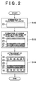
- FIG. 2 is a process chart illustrating a process of manufacturing the fuel cell according to the first embodiment of the invention.
- the electrolyte layer 23 is produced in step S10.
- the dense layers 21, 22, and 24 are formed on both sides of this electrolyte layer 23 in step S12.
- each of the electrodes 10 and 30 is attached to a respective outer surface of the dense layers 21 and 24 in step S14.
- each of the catalyst layers can be properly formed in accordance with its position in the respective process step.
- the moisture of the electrolyte layer 23 can be retained within the electrolyte layer 23.
- operation of the fuel cell at a relatively high temperature is enabled.
- the fuel cell can be operated at about 200°C.
- FIG. 3 is an explanatory view illustrating a layer configuration table of respective constituent cells of the solid polymer membrane fuel cell according to the first embodiment and modifications thereof.
- Case A corresponds to the structure of the first embodiment illustrated in FIG. 1. That is, this constituent cell has a structure in which the oxygen-electrode-side dense layer consisting of a layer of vanadium-nickel alloy (V-Ni) and a layer of palladium (Pd) is provided between the electrolyte layer and the oxygen electrode, and in which the hydrogen-electrode-side dense layer of palladium (Pd) is provided between the electrolyte layer and the hydrogen electrode.
- V-Ni vanadium-nickel alloy
- Pd palladium
- the fuel cell of the first embodiment has the dense layers provided on respective sides of the electrolyte layer. Therefore, for example, the constituent cell may have a structure provided with an oxygen-electrode-side dense layer of a vanadium-nickel alloy (V-Ni) and a hydrogen-electrode-side dense layer of palladium (Pd) as in Case B.
- both the oxygen-electrode-side dense layer and the hydrogen-electrode-side dense layer may be formed from palladium (Pd).
- vanadium (V) or other alloys containing vanadium may be used as the material of the oxygen-electrode-side dense layer, instead of the vanadium-nickel alloy (V-Ni).
- niobium, tantalum, and other alloys that respectively contain at least a part of these elements can be used as the material of the oxygen-electrode-side dense layer.
- these materials have high hydrogen permeability and are relatively low in price, and are thus suitable for this application.
- the reason for using materials, such as vanadium (V), in the oxygen-electrode side dense layer is that these materials have a tendency to suffer from hydrogen embrittlement. However, this does not means that these materials cannot be used as the material for the hydrogen-electrode-side dense layer.
- a palladium alloy can be used as the material of the hydrogen-electrode-side dense layer, instead of palladium (Pd).
- Palladium (Pd) has relatively high hydrogen permeability and is resistant to hydrogen brittleness. It should be noted that the modifications shown in FIG. 3 are only illustrative. Dense layers made of various materials can be applied to the solid polymer membrane fuel cell according to the invention.
- a sandwich structure membrane composed of a layer of palladium (Pd)/a layer of vanadium (V)/and a layer of palladium (Pd) may be used as the hydrogen permeable material of the dense layer.
- Vanadium (V) has advantages in that it has a higher rate of permeation of protons and hydrogen atoms than palladium (Pd), and is also lower in price.
- vanadium (V) has the disadvantage that it has a limited ability to separate hydrogen molecules into protons, etc.
- the permeability of the membrane is enhanced by forming a thin layer of palladium (Pd), which has a high ability to separate hydrogen molecules into protons and electrons, on one or both of sides of the layer of vanadium (V).
- the electrolyte layer 23 is not limited to being a solid polymer membrane. Membranes that include moisture within a ceramic, glass, or alumina-based material, for example, a heteropoly acid-based or ⁇ -alumina-based material, may be used as the electrolyte layer 23. When such materials are used, the fuel cell can be operated at about 300°C.
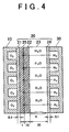
- FIG. 4 is an explanatory view schematically illustrating a first configuration of the solid polymer membrane fuel cell having a metal diffusion suppression layer.
- the figure shows a cross-section of a constituent cell of the fuel cell.
- the basic constituent elements thereof are similar to those of the fuel cell shown in FIG. 1.
- the cell shown in FIG. 4 differs from that shown in FIG. 1 in that a metal diffusion suppression layer 25 is formed along the respective boundary surfaces of the dense layer 21 of palladium (Pd) and the dense layer 22 of the vanadium-nickel alloy (V-Ni).
- the hydrogen permeability of the hydrogen permeable material lowers with time or during heat treatment executed during manufacturing owing to mutual diffusion of the different kinds of metal.
- the electromotive force of the fuel cell decreases.
- the metal diffusion suppression layer 25 it is possible to inhibit the mutual diffusion of the different kinds of metal, and suppress the reduction in the hydrogen permeability of the hydrogen permeable material.
- the metal diffusion suppression layer 25 is a dense element that has a thickness which is set to 1 ⁇ m.
- the thickness of the metal diffusion suppression layer 25 can be set as chosen.
- tungsten oxide (WO 3 ) is used as the material of the metal diffusion suppression layer 25 in the first embodiment, the material of the metal diffusion suppression layer 25 is not limited thereto.
- a proton conductor, a mixed conductor, a ceramic, composites of these materials, and a gradient material may be used as the material of the metal diffusion suppression layer 25.
- the proton conductors may be composite oxides, such as perovskite oxides and pyrochlore oxides, and spinel oxides
- the mixed conductor may be, for instance, MnO 3 .
- FIG. 5 is an explanatory view schematically illustrating a second configuration of the solid polymer membrane fuel cell having the metal diffusion suppression layer.
- the figure shows a cross-section of a constituent cell of the fuel cell.
- the basic constituent elements thereof are similar to those of the fuel cell shown in FIG. 1.
- the cell shown in FIG. 5 differs from that shown in FIG. 1 in that the metal diffusion suppression layer 25 is discontinuously formed in an island-like arrangement along the boundary surface between the dense layer 21 of palladium (Pd) and the dense layer 22 of the vanadium-nickel alloy (V-Ni).
- the thickness of the metal diffusion suppression layer 25 is set in this embodiment to be 1 ⁇ m, the thickness of the layer 25 can be set as chosen.
- nickel (Ni) which is a proton-nonconductive metal
- the material of the layer 25 is not limited thereto.
- a proton conductor, a mixed conductor, an insulating material, a proton-nonconductive metal, ceramics, composites of these materials, and a gradient material may be used as the material of the metal diffusion suppression layer 25.
- the proton conductor are composite oxides, such as perovskite oxides and pyrochlore oxides, and spinel oxides.
- An example of the mixed conductor is MnO 3 .
- the insulating material examples include Al 2 O 3 , SiO 2 , and MgO.
- An example of the proton-nonconductive metal is Co. It should be noted that, particularly in the case of employing an insulating material for the metal diffusion suppression layer 25, it is effective to discontinuously provide the metal diffusion suppression layer 25 in the island-like arrangement because the insulating material does not have proton-conductivity.
- FIG. 6 is an explanatory view schematically illustrating the configuration of a solid oxide fuel cell according to a second embodiment of the invention.
- This figure shows a cross-section of a constituent cell of this fuel cell.
- This constituent cell has a structure in which an electrolyte membrane 40 is sandwiched between the oxygen electrode 10 and the hydrogen electrode 30.
- the structure and material of the oxygen electrode 10 and the hydrogen electrode 30, respectively, are the same as those of the oxygen electrode and the hydrogen electrode of the solid polymer membrane fuel cell described with regard to the first embodiment.
- the electrolyte membrane 40 has a five-layer structure in which a dense substrate 43 formed from vanadium (V) is centrally disposed. Thin layers respectively constituted by electrolyte layers 42 and 44 that are made of a solid oxide are formed on both sides of the substrate 43. A barium-cerate-based (BaCeO 3 -based) ceramic proton conductor or a strontium-cerate-based (SrCeO 3 -based) ceramic proton conductor may be used as the material for the electrolyte layers 42 and 44. Coatings 41 and 45 of palladium (Pd) are provided on the outer surfaces of the electrolyte layers 42 and 44, respectively.
- the thickness of the coatings 41 and 45 of palladium (Pd) is set to be 0.1 ⁇ m.
- the thickness of the electrolyte layers 42 and 44 is set to be 1 ⁇ m.
- the thickness of the substrate 43 is set to be 40 ⁇ m.
- the thickness of each of the layers can be set as chosen.
- palladium (Pd) for example, vanadium (V), niobium (Nb), tantalum (Ta), an alloy containing at least a part of these elements, or a palladium (Pd) alloy may be used for the material of the coatings 41 and 45.
- the electrolyte layer can be protected by using such coatings.
- the substrate 43 is formed from a kind of metallic material that is different to that of the metallic material of the coatings 41 and 45.
- alloying happens at the contact surface of different kinds of metal owing to mutual diffusion.
- the electrolyte membrane is interposed between the different kinds of metal, which offers the advantage that the properties of both the metals can be utilized whilst alloying is inhibited from occurring.
- a combination of one of vanadium (V), niobium (Nb), tantalum (Ta), and an alloy containing at least a part of these elements, with palladium (Pd) or a palladium (Pd) alloy may be employed for the different kinds of metal.
- the substrate 43 may consists of at least two hydrogen separation layers respectively formed from different kinds of metal. Further, a metal diffusion suppression layer for suppressing the diffusion of the different kinds of metal may be provided, at the least, at a portion of the contact interface between the different kinds of metal.
- the substrate 43 may be formed from one of vanadium (V), niobium (Nb), tantalum (Ta), and an alloy containing at least a part of these elements. These materials have high hydrogen permeability and are relatively low in price. Consequently, a substrate having sufficient thickness can be formed at low cost.
- a catalyst layer formed from platinum (Pt) and the like is provided within the constituent cell so as to accelerate reactions in an electric power generation process at the hydrogen electrode and the oxygen electrode.
- catalyst layers can be provided, for instance, between the electrolyte membrane 40 and the oxygen electrode 10, and between the electrolyte membrane 40 and the hydrogen electrode 30. Additionally, catalyst layers can be provided between the coating 41 and the electrolyte layer 42, between the coating 45 and the electrolyte layer 44, and between the substrate 43 and each of the electrolyte layers 42 and 44.
- FIG. 7 is a process chart illustrating a process of manufacturing the fuel cell according to the second embodiment.
- the substrate 43 is produced in step S20.
- the electrolyte layers 42 and 44 are respectively formed on both sides of this substrate 43 in step S22.
- the formation of the electrolyte layers 42 and 44 is executed by producing electrolyte. The method of producing this electrolyte will be described later.
- the substrate 43 is dense, and thus each of the electrolyte layers 42 and 44 can be formed as a sufficiently thin layer.
- Various techniques for example, physical deposition, chemical deposition, and sputtering can be used for forming the layer.
- Pd coatings 41 and 45 are formed on the outer surfaces of the electrolyte layers 42 and 44, respectively. Further, the electrodes 10 and 30 are attached to the electrolyte membrane 40 in step S44. With regard to the catalyst layers, they may be suitably formed in accordance with their position during one of the steps.
- the fuel cell can be operated at a relatively low temperature.
- the fuel cell can be operated at about 600°C.
- the operating temperature of the fuel cell can be lowered to about 400°C.
- FIG. 8 is an explanatory view illustrating a layer configuration table of a constituent cell of the solid oxide fuel cell according to the second embodiment of the invention and modifications thereof.
- Case A corresponds to the structure of the second embodiment illustrated in FIG. 6. That is, this constituent cell has a structure in which the electrolyte layers are provided on both sides of the dense substrate of vanadium (V). Furthermore, the coatings of palladium (Pd) are provided on the outer surfaces of the electrolyte layers, respectively. In this figure, for ease of drawing, the coatings are not distinguished from the substrate, so that the substrate and the coatings are indicated as the "substrate". Moreover, for the convenience of description, the layers are respectively designated by "layer names" L1 to L5 from the oxygen electrode side.
- the electrolyte layers are provided on the dense substrate, respectively.
- the substrate of vanadium (V) is formed for layer L1, and then the electrolyte membrane can be formed on the hydrogen-electrode-side surface of the substrate of vanadium (V) as layer L2.
- a coating of palladium (Pd) can be formed on the oxygen-electrode-side surface of the substrate of vanadium (V).
- a coating of palladium (Pd) is formed on the hydrogen-electrode-side surface of the electrolyte layer L2 as layer L3.
- layer L3 in Case B can be omitted.
- Cases B and C different kinds of metal, that is, palladium (Pd) and vanadium (V), are in contact with each other in layer L1.
- Pd palladium
- V vanadium
- the cells in Cases B and C are operated at about 400°C.
- the thickness of the electrolyte layer is set to be 0.1 ⁇ m.
- Case D it is possible to omit layer L1 of Case B.
- layer L1 it is preferable to avoid direct contact between the solid oxide electrolyte layer and the oxygen electrode. Bearing this in mind, it is preferable that layer L1 is not omitted.
- FIG. 9 is an explanatory view schematically illustrating a first configuration of a solid oxide fuel cell having a metal diffusion suppression layer and a reaction suppression layer according to the second embodiment.
- This figure shows a cross-section of a constituent cell of the fuel cell.
- An electrolyte membrane 50 has a five-layer structure in which a dense substrate 53 formed from vanadium (V) is centrally located.
- a metal diffusion suppression layer 54 which is a dense element, is provided on the surface of the substrate 53 at the hydrogen-electrode 30 side. Further, a coating 55 of palladium (Pd) is provided on the outer surface of the metal diffusion suppression layer 54.
- a reaction suppression layer 52 which is a dense element, is provided on the surface of the substrate 53 at the oxygen electrode 10 side.
- an electrolyte layer 51 which is a thin membrane, is constituted by a solid oxide, is formed on the outer surface of the reaction suppression layer 52.
- the electrolyte layer is made of a solid oxide material, oxygen contained in the electrolyte layer reacts with the substrate when the electrolyte layer is in contact with the substrate. Thus, the substrate becomes an oxide.
- the hydrogen permeability lowers and the electromotive force of the fuel cell decreases to a level that is lower than a normal level.
- a metal oxide SrCeO 3 which is a perovskite oxide, is used as the material of the electrolyte layer 51.
- the thickness of the coating 55 of palladium (Pd) is set to be 0.2 ⁇ m; the thickness of the metal diffusion suppression layer 54 is set to be 1 ⁇ m; the thickness of the reaction suppression layer 52 is set to be 0.2 ⁇ m; the thickness of the electrolyte layer 51 is set to be 0.1 ⁇ m; and the thickness of the substrate 53 is set to be 40 ⁇ m.
- the thickness of each of the layers can be set as chosen.
- a proton conductor, a mixed conductor, or an insulator is used for the reaction suppression layer 52.
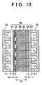
- FIG. 10 is an explanatory view schematically illustrating a second configuration of the second embodiment of the solid oxide fuel cell having a metal diffusion suppression layer and a reaction suppression layer.
- This figure illustrates a cross-section of a constituent cell of this fuel cell.
- the fuel cell shown in this figure differs from the solid oxide fuel cell shown in FIG. 9 in that dense elements 56 of palladium (Pd) are discontinuously formed in an island-like arrangement along the boundary surface between the reaction suppression layer 52 and the substrate 53.
- the dense elements 56 separate hydrogen molecules into protons and electrons and are thus effective for providing an electromotive force.
- FIG. 11 is an explanatory view schematically illustrating a third configuration of the second embodiment of the solid oxide fuel cell having a metal diffusion suppression layer and a reaction suppression layer. This figure illustrates a cross-section of a constituent cell of the fuel cell.
- the solid oxide fuel cell shown in this figure differs from that shown in FIG. 9 in that the reaction suppression layer 52 is not continuously but discontinuously formed in an island-like arrangement along the boundary surface between the electrolyte layer 51 and the substrate 53; and also differs in that the metal diffusion suppression layer 54 is not continuously but discontinuously formed in an island-like arrangement along the boundary surface between the substrate 53 and the coating 55.
- the thickness of the metal diffusion layer 54 is 1 ⁇ m, and that of the reaction suppression layer 52 is 0.2 ⁇ m.
- the thickness of each of the layers can be set as chosen. In the case that the metal diffusion suppression layer 54 and the reaction suppression layer 52 are insulators, they do not have proton conductivity. Therefore, it is effective to discontinuously arrange the metal diffusion suppression layer 54 and the reaction suppression layer 52 as illustrated in FIG. 11.
- Each of the solid oxide fuel cells illustrated in FIGs. 9 to 11 has the reaction suppression layer 52 provided along the boundary surface between the substrate 53 formed from vanadium (V) and the electrolyte layer 51 formed from a metal oxide.
- V vanadium
- the suppression layer 52 it is possible to inhibit reduction of the electromotive force of the fuel cell caused by being formed on the boundary surface.
- each of these solid oxide fuel cells has the metal diffusion suppression layer 54 along the boundary surface between the substrate 53 formed from vanadium (V) and the coating 55 of palladium.
- V vanadium
- the electrolyte is a perovskite-type composite oxide.
- Perovskite-type composite oxides are oxides generally represented by the formula ABO 3 . It should be noted that it is assumed herein that the A-site element in this formula is an alkali metal element.
- FIG. 12 is an explanatory view illustrating a first way of generating electrolytes according to the second embodiment of the invention.
- the upper part of this figure represents a state of a molecule when the electrolyte is not yet produced, while the lower part of the figure represents a state of the molecule when the electrolyte has already been produced.
- the molar concentration of AO is less than that of BO 2 .
- FIG. 13 is an explanatory view illustrating a second way of generating electrolytes according to the second embodiment of the invention.
- the upper part of this figure represents a state of a molecule when the electrolyte is not yet produced, while the lower part of the figure represents a state of the molecule when the electrolyte has already been produced.
- an oxide MO 2 that reacts with the alkali metal A-site element to form an oxide is included in the molecule, in addition to AO and BO 2 .
- ABO 3 and AMO 3 are produced, and BO 2 remains.
- the molar concentration of AO is less than the sum of the molar concentrations of BO 2 and MO 2 .
- the oxide MO 2 which reacts with the alkali metal to form an oxide, is, for example, TiO 2 , MnO 2 , or Fe 2 O 3 .
- the oxide MO 2 reacts with the alkali metal A to form an oxide, for instance, ATiO 3 , AMnO 3 , or AFeO 3 .
- a rare-earth element may be employed as the B-site element.
- the rare-earth element is, for instance, cerium (Ce), zirconium (Zr), yttrium (Y), and ytterbium (Yb).
- alkali metal oxide (AO) reacts with carbon dioxide (CO 2 ) contained in cathode and anode gases, to produce a carbonate. This carbonate can cause reduction in electric conductivity and breakdown of the electrolyte layer. Therefore, it is preferable that alkali metal oxide (AO) does not exist independently after the electrolyte is produced. According to the methods of generating the electrolyte illustrated in FIGs. 12 and 13, AO, that is, the alkali metal oxide, does not exists independently after the electrolyte is generated.
- the method of producing the electrolyte according to the second embodiment of the invention can be applied not only to the electrolyte, which is the perovskite type composite oxide, but to electrolytes that are pyrochlore oxides (A 2 B 2 O 7 ) and spinel oxides (ABO 4 ). Moreover, the electrolyte may contain impurities. Therefore, the method of producing the electrolyte according to the second embodiment of the invention can be applied to electrolytes such as (A 0.8 a 0.2 ) BO 3 and ABCO x .
- the invention provides an electrolyte membrane that allows an operating temperature of a solid polymer membrane fuel cell to be increased, and an operating temperature of a solid oxide fuel cell to be lowered.
- This electrolyte membrane can be used in a fuel cell that is operable in an intermediate temperature range.
- the invention also provides a fuel cell using such an electrolyte membrane.
- dense layers (21, 22 and 24) made of hydrogen permeable metal are provided on both sides of a polymer electrolyte layer (20) in a solid polymer membrane fuel cell. Consequently, the run-off of moisture contained in the electrolyte layer (20) can be inhibited. Moreover, the operating temperature of the fuel cell can be raised.
- a dense layer made of a hydrogen permeable metal is employed as a substrate (43, 53), and electrolyte layers are formed on the substrate. Consequently, the electrolyte layers can be made sufficiently thin, and furthermore, the operating temperature of the solid oxide fuel cell can be lowered.
Landscapes
- Engineering & Computer Science (AREA)
- Manufacturing & Machinery (AREA)
- Life Sciences & Earth Sciences (AREA)
- Sustainable Development (AREA)
- Sustainable Energy (AREA)
- Chemical & Material Sciences (AREA)
- Chemical Kinetics & Catalysis (AREA)
- Electrochemistry (AREA)
- General Chemical & Material Sciences (AREA)
- Fuel Cell (AREA)
- Conductive Materials (AREA)
Abstract
Description
The invention provides an electrolyte membrane that allows an operating temperature of a solid polymer membrane fuel cell to be increased, and an operating temperature of a solid oxide fuel cell to be lowered. This electrolyte membrane can be used in a fuel cell that is operable in an intermediate temperature range. The invention also provides a fuel cell using such an electrolyte membrane. According to the invention, dense layers (21, 22 and 24) made of hydrogen permeable metal are provided on both sides of a polymer electrolyte layer (20) in a solid polymer membrane fuel cell. Consequently, the run-off of moisture contained in the electrolyte layer (20) can be inhibited. Moreover, the operating temperature of the fuel cell can be raised. On the other hand, in a solid oxide fuel cell, a dense layer made of a hydrogen permeable metal is employed as a substrate (43, 53), and electrolyte layers are formed on the substrate. Consequently, the electrolyte layers can be made sufficiently thin, and furthermore, the operating temperature of the solid oxide fuel cell can be lowered.
Claims (26)
- An electrolyte membrane (20) for a fuel cell, characterised by comprising:a hydrated electrolyte layer (23) containing moisture; anddense layers (21, 22, 24) made of a hydrogen permeable material and formed on both sides of the electrolyte layer.
- The electrolyte membrane (20) according to claim 1, characterised in that the hydrated electrolyte layer (23) is a solid polymer membrane.
- The electrolyte membrane (20) according to claim 1, characterised in that the dense layer (21, 22, 24) disposed at an oxygen electrode (10) side of the fuel cell is formed from one of vanadium, niobium, tantalum, and an alloy containing at least a part of vanadium, niobium, and tantalum.
- The electrolyte membrane (20) according to one of claims 1 to 3, characterised in that the dense layer (21, 22, 24) disposed at a hydrogen electrode (30) side of the fuel cell is formed from one of palladium and a palladium alloy.
- The electrolyte membrane (20) according to claim 1, characterised in that the dense layer (21, 22, 24) made of a hydrogen permeable material includes at least two hydrogen separation membrane layers respectively made of different kinds of metal, and a metal diffusion suppression layer (25), provided on at least a part of a contact interface between the separation membrane layers made of different kinds of metal, for suppressing diffusion of the different kinds of metal.
- The electrolyte membrane (20) according to claim 5, characterised in that the metal diffusion suppression layer (25) includes at least one of a proton conductor, a mixed conductor, an insulating material, a ceramic, and a proton-nonconductive metal.
- A fuel cell, characterised by comprising:the electrolyte membrane (20) as disclosed in any of claims 1 through 6,an oxygen electrode (10) disposed on one side of the electrolyte membrane;an oxidizing gas supply portion that supplies oxidizing gas to the oxygen electrode;a hydrogen electrode (30) disposed on the other side of the electrolyte membrane; anda fuel gas supply portion that supplies a hydrogen-rich fuel gas to the hydrogen electrode.
- An electrolyte membrane (40,50) for a fuel cell, characterised by comprising:a substrate (43, 53) formed from a dense hydrogen permeable material; andan inorganic electrolyte layer (42, 44, 51) formed on at least one side of the substrate.
- The electrolyte membrane (40, 50) according to claim 8, characterised in that a surface of a side of the electrolyte layer (42, 44, 51) that is not in contact with the substrate (43, 53) is coated with a coating (41, 45, 55) made of a hydrogen permeable material.
- The electrolyte membrane (40,50) according to claim 9, characterised in that the substrate (43, 53) and the coating (41, 45, 55) are formed from different kinds of metallic materials, respectively.
- The electrolyte membrane (40, 50) according to claim 8, characterised in that the substrate (43, 53) made of a hydrogen permeable material includes at least two hydrogen separation membrane layers made of different kinds of metal, and a metal diffusion suppression layer (54), provided on at least a part of a contact interface between the separation membrane layers made of different kinds of metal, for suppressing diffusion of the different kinds of metal.
- The electrolyte membrane (40, 50) according to claim 11, characterised in that the metal diffusion suppression layer (54) contains at least one of a proton conductor, a mixed conductor, an insulating material, a ceramic, and a proton-nonconductive metal.
- The electrolyte membrane (40, 50) according to any one of claims 8 to 12, characterised in that the substrate (43,53) is formed from one of vanadium, niobium, tantalum, and an alloy containing at least a part of vanadium, niobium, and tantalum.
- The electrolyte membrane (40,50) according to any one of claims 8 to 13, characterised in that the electrolyte layer (42,44,51) is formed from a solid oxide, and the electrolyte membrane has a reaction suppression layer (52), provided on at least a part of an interface between the substrate (43, 53) and the electrolyte layer, for suppressing a reaction between oxygen atoms, which are contained in the electrolyte layer (42, 44, 51), and the substrate.
- The electrolyte membrane (40, 50) according to claim 14, characterised in that the reaction suppression layer (52) contains at least one of a proton conductor, a mixed conductor, and an insulating material.
- The electrolyte membrane (40, 50) according to claim 8, characterised in that an electrolyte of the electrolyte layer (42, 44, 51) is a composite oxide containing an A-site material having an alkali metal element as a principal component, and a B-site material having another element as a principal component, such that a molar ratio of the A-site material to the B-site material is constant, and also containing a predetermined amount of oxygen; the composite oxide is synthesized by a reaction between the A-site material and the B-site material, and during this reaction, the molar ratio of the A-site material to the B-site material is smaller than the constant molar ratio.
- The electrolyte membrane (40,50) according to claim 8, characterised in that an electrolyte of the electrolyte layer (42, 44, 51) is a composite oxide containing an A-site material having an alkali metal element as a principal component, and a B-site material having another element as a principal component, such that a molar ratio of the A-site material to the B-site material is constant, and also containing a predetermined amount of oxygen; and the composite oxide is synthesized in a state in which the composite oxide contains a predetermined amount of an oxide of a third material that forms an oxide together with the alkali metal element.
- A fuel cell, characterised by comprising:the electrolyte membrane (40, 50) as disclosed in any of claims 8 through 17,an oxygen electrode (10) disposed on one side of the electrolyte membrane;an oxidizing gas supply portion that supplies an oxidizing gas to the oxygen electrode;a hydrogen electrode (30) disposed on the other side of the electrolyte membrane; anda fuel gas supply portion that supplies a hydrogen-rich fuel gas to the hydrogen electrode.
- The fuel cell according to claim 18, characterised in that a material of the substrate (43, 53) is one of vanadium, niobium, tantalum, and an alloy containing at least a part of vanadium, niobium, and tantalum; and the electrolyte layer (42, 44, 51) is disposed in such a way as to be closer to the hydrogen electrode (30) than the substrate.
- The fuel cell according to claims 18 or 19, characterised in that the electrolyte membrane (40, 50) is disposed so that at least one of the substrate (43, 53) and the coating (41, 45, 55) is interposed between the electrolyte layer (42, 44, 51) and the oxygen electrode (10).
- A method of manufacturing an electrolyte membrane (20) for a fuel cell, characterised by comprising the steps of:forming a hydrated electrolyte layer (23) that contains moisture; andforming dense layers (21, 22, 24)s made of a hydrogen permeable material on both sides of the electrolyte layer.
- A method of manufacturing an electrolyte membrane (40, 50) for a fuel cell, characterised by comprising the steps of:preparing a substrate (43, 53) formed from a dense hydrogen permeable material; andforming an inorganic electrolyte layer (42, 44, 51) on at least one side of the substrate.
- The method of manufacturing an electrolyte membrane (40, 50) according to claim 22, characterised by further comprising the step of synthesizing a composite oxide, which contains a constant molar ratio of an A-site material having an alkali metal element as a principal component and a B-site material having another element as a principal component, and which also contains a predetermined amount of oxygen, in a state in which the molar ratio of the A-site component to the B-site component is smaller than the constant ratio.
- A method of manufacturing an electrolyte membrane (40, 50) according to claim 22, characterised by further comprising the step of synthesizing a composite oxide, which contains a constant molar ratio of an A-site material having an alkali metal element as a principal component, and a B-site material having another element as a principal component, and also contains a predetermined amount of oxygen, in a state in which the composite oxide contains a predetermined amount of an oxide of a third material that forms an oxide together with the alkali metal element.
- A method of manufacturing a fuel cell, characterised by comprising the steps of:forming an electrolyte membrane (20) by forming a dense layer (21, 22, 24) of a hydrogen permeable material on both surfaces of a hydrated electrolyte layer (23) containing moisture ;arranging an oxygen electrode (10) and an oxidizing gas supply portion that supplies oxidizing gas to the oxygen electrode on one side of the electrolyte membrane; andarranging a hydrogen electrode (30) and a fuel gas supply portion that supplies a hydrogen-rich fuel gas to the hydrogen electrode on the other side of the electrolyte membrane.
- A method of manufacturing a fuel cell characterised by comprising the steps of:forming an electrolyte membrane (40, 50) by forming a substrate (43, 53) formed from a dense hydrogen permeable material, and forming an inorganic electrolyte layer (42, 44, 51) on at least one side of the substrate;arranging an oxygen electrode (10) and an oxidizing gas supply portion that supplies an oxidizing gas to the oxygen electrode on one side of the electrolyte membrane; andarranging a hydrogen electrode (30) and a fuel gas supply portion that supplies a hydrogen-rich fuel gas to the hydrogen electrode on the other side of the electrolyte membrane.
Applications Claiming Priority (4)
| Application Number | Priority Date | Filing Date | Title |
|---|---|---|---|
| JP2002248054 | 2002-08-28 | ||
| JP2002248054 | 2002-08-28 | ||
| JP2003072994A JP4079016B2 (en) | 2002-08-28 | 2003-03-18 | Fuel cell that can operate in the middle temperature range |
| JP2003072994 | 2003-03-18 |
Publications (3)
| Publication Number | Publication Date |
|---|---|
| EP1394884A2 true EP1394884A2 (en) | 2004-03-03 |
| EP1394884A3 EP1394884A3 (en) | 2008-10-08 |
| EP1394884B1 EP1394884B1 (en) | 2013-10-23 |
Family
ID=31497679
Family Applications (1)
| Application Number | Title | Priority Date | Filing Date |
|---|---|---|---|
| EP03019390.8A Expired - Lifetime EP1394884B1 (en) | 2002-08-28 | 2003-08-27 | Electrolyte membrane for fuel cell operable in medium temperature range, fuel cell using the same, and manufacturing methods therefor |
Country Status (3)
| Country | Link |
|---|---|
| US (1) | US7491462B2 (en) |
| EP (1) | EP1394884B1 (en) |
| JP (1) | JP4079016B2 (en) |
Cited By (10)
| Publication number | Priority date | Publication date | Assignee | Title |
|---|---|---|---|---|
| WO2005104276A1 (en) * | 2004-04-23 | 2005-11-03 | Toyota Jidosha Kabushiki Kaisha | Electrolyte layer for fuel cell, fuel cell, and method of manufacturing electrolyte layer for fuel cell |
| JP2005310698A (en) * | 2004-04-26 | 2005-11-04 | Toyota Motor Corp | Manufacturing method of electrolyte membrane for fuel cell |
| WO2006062146A1 (en) * | 2004-12-09 | 2006-06-15 | Toyota Jidosha Kabushiki Kaisha | Fuel cell |
| WO2006018705A3 (en) * | 2004-08-18 | 2006-09-08 | Toyota Motor Co Ltd | Membrane-electrode assembly and fuel cell |
| WO2006095910A1 (en) * | 2005-03-08 | 2006-09-14 | Toyota Jidosha Kabushiki Kaisha | Hydrogen-generating apparatus and fuel cell system |
| WO2006106403A1 (en) * | 2005-04-05 | 2006-10-12 | Toyota Jidosha Kabushiki Kaisha | Hydrogen generation device and fuel cell system including same |
| WO2006106404A1 (en) * | 2005-04-05 | 2006-10-12 | Toyota Jidosha Kabushiki Kaisha | Hydrogen generation device and fuel cell system including same |
| WO2006062045A3 (en) * | 2004-12-08 | 2007-07-19 | Toyota Motor Co Ltd | Solid electolyte and manufacturing method of the same |
| EP1650825A4 (en) * | 2003-07-31 | 2008-08-06 | Toyota Motor Co Ltd | FUEL CELL STACK, FUEL CELL SYSTEM, AND METHOD FOR PRODUCING FUEL CELL STACKS |
| EP2333888A3 (en) * | 2009-12-10 | 2013-05-01 | Delphi Technologies, Inc. | Low-Resistance ceramic electrode for a solid oxide fuel cell |
Families Citing this family (42)
| Publication number | Priority date | Publication date | Assignee | Title |
|---|---|---|---|---|
| JP4543612B2 (en) | 2003-03-11 | 2010-09-15 | トヨタ自動車株式会社 | Fuel cell system |
| EP1619736A4 (en) * | 2003-03-18 | 2008-06-04 | Toyota Motor Co Ltd | FUEL CELL AND METHOD FOR MANUFACTURING ELECTROLYTE MEMBRANE FOR FUEL CELL |
| US20050064259A1 (en) * | 2003-09-24 | 2005-03-24 | Protonetics International, Inc. | Hydrogen diffusion electrode for protonic ceramic fuel cell |
| CN100435398C (en) * | 2003-11-04 | 2008-11-19 | 丰田自动车株式会社 | Fuel cell system and mobile body |
| JP4186810B2 (en) | 2003-12-08 | 2008-11-26 | トヨタ自動車株式会社 | Fuel cell manufacturing method and fuel cell |
| JP2005190684A (en) * | 2003-12-24 | 2005-07-14 | Toyota Motor Corp | Fuel cell |
| JP4385761B2 (en) * | 2003-12-24 | 2009-12-16 | トヨタ自動車株式会社 | Fuel cell |
| EP1715540B1 (en) * | 2004-01-14 | 2013-05-22 | Toyota Jidosha Kabushiki Kaisha | Fuel cell power generating device |
| JP2005243416A (en) | 2004-02-26 | 2005-09-08 | Toyota Motor Corp | Fuel cell system |
| JP2005251550A (en) * | 2004-03-04 | 2005-09-15 | Toyota Motor Corp | Fuel cell |
| JP4876373B2 (en) * | 2004-04-23 | 2012-02-15 | トヨタ自動車株式会社 | Cathode for fuel cell and method for producing the same |
| JP4193750B2 (en) * | 2004-04-26 | 2008-12-10 | トヨタ自動車株式会社 | Hydrogen separation membrane, fuel cell, and method for producing the hydrogen separation membrane and fuel cell |
| JP4661102B2 (en) * | 2004-06-23 | 2011-03-30 | トヨタ自動車株式会社 | Manufacturing method of electrolyte membrane for fuel cell and fuel cell |
| US20060008696A1 (en) * | 2004-06-30 | 2006-01-12 | Suk-Won Cha | Nanotubular solid oxide fuel cell |
| JP4934949B2 (en) * | 2004-07-20 | 2012-05-23 | トヨタ自動車株式会社 | Fuel cell, hydrogen separation membrane module, and manufacturing method thereof |
| JP4607510B2 (en) | 2004-07-26 | 2011-01-05 | トヨタ自動車株式会社 | Hydrogen permeable membrane |
| JP4715135B2 (en) * | 2004-09-08 | 2011-07-06 | トヨタ自動車株式会社 | Fuel cell manufacturing method and fuel cell |
| US7955491B2 (en) * | 2004-09-14 | 2011-06-07 | Honda Motor Co., Ltd. | Methods, devices, and infrastructure systems for separating, removing, compressing, and generating hydrogen |
| US20060083852A1 (en) * | 2004-10-18 | 2006-04-20 | Yoocham Jeon | Fuel cell apparatus and method of manufacture thereof |
| JP2006248813A (en) * | 2005-03-08 | 2006-09-21 | Toyota Motor Corp | Hydrogen generator and fuel cell system |
| JP2006282457A (en) * | 2005-03-31 | 2006-10-19 | Toyota Motor Corp | Hydrogen generator and fuel cell system |
| JP2006282458A (en) * | 2005-03-31 | 2006-10-19 | Toyota Motor Corp | Hydrogen generator and fuel cell system |
| JP4704789B2 (en) | 2005-03-31 | 2011-06-22 | 株式会社豊田中央研究所 | Hydrogen fuel supply system and fuel cell system |
| JP2006318870A (en) * | 2005-05-16 | 2006-11-24 | Toyota Motor Corp | Fuel cell system and fuel cell |
| JP4972884B2 (en) * | 2005-06-17 | 2012-07-11 | トヨタ自動車株式会社 | Fuel cell |
| JP2007045677A (en) * | 2005-08-11 | 2007-02-22 | Toyota Motor Corp | Hydrogen generator and fuel cell system |
| KR100953613B1 (en) * | 2005-09-28 | 2010-04-20 | 삼성에스디아이 주식회사 | Membrane-electrode assembly for fuel cell, method for manufacturing same and fuel cell system comprising same |
| JP2007103262A (en) * | 2005-10-06 | 2007-04-19 | Toyota Motor Corp | Manufacturing method of fuel cell |
| JP2007103223A (en) | 2005-10-06 | 2007-04-19 | Toyota Motor Corp | Fuel cell and manufacturing method thereof |
| WO2007045111A1 (en) * | 2005-10-19 | 2007-04-26 | Eidgenössische Technische Hochschule Zürich | Thin film and composite element produced from the same |
| CN101326670A (en) * | 2005-10-19 | 2008-12-17 | 瑞士联邦苏黎世技术大学 | Compositions of thin films and glass-ceramic substrates for use as micro-electrochemical devices |
| JP5061456B2 (en) | 2005-12-14 | 2012-10-31 | トヨタ自動車株式会社 | Manufacturing method of fuel cell |
| CN101351268B (en) | 2005-12-28 | 2012-06-13 | 株式会社日立制作所 | Catalyst having dehydrogenation or hydrogenation function, fuel cell and hydrogen storage and supply device using the catalyst |
| JP4929720B2 (en) * | 2006-01-10 | 2012-05-09 | トヨタ自動車株式会社 | Fuel cell |
| JP2007207664A (en) | 2006-02-03 | 2007-08-16 | Toyota Motor Corp | Fuel cell system |
| JP5040123B2 (en) | 2006-02-28 | 2012-10-03 | トヨタ自動車株式会社 | Proton conducting electrolyte and electrochemical cell using the same |
| JP5082290B2 (en) * | 2006-04-27 | 2012-11-28 | トヨタ自動車株式会社 | Fuel cell with high heat utilization efficiency |
| JP5061544B2 (en) | 2006-09-05 | 2012-10-31 | トヨタ自動車株式会社 | Fuel cell |
| JP2008108647A (en) * | 2006-10-26 | 2008-05-08 | Tokyo Gas Co Ltd | Reformer integrated fuel cell |
| KR20110101976A (en) * | 2010-03-10 | 2011-09-16 | 삼성전자주식회사 | Solid oxide fuel cell and manufacturing method thereof |
| KR20120037839A (en) * | 2010-10-12 | 2012-04-20 | 삼성전자주식회사 | Membrane electrode assembly, solid oxide fuel cell comprising the assembly and preparation method thereof |
| WO2016063537A1 (en) * | 2014-10-23 | 2016-04-28 | 国立研究開発法人科学技術振興機構 | Proton conductor and fuel cell |
Family Cites Families (23)
| Publication number | Priority date | Publication date | Assignee | Title |
|---|---|---|---|---|
| GB1100102A (en) | 1964-04-25 | 1968-01-24 | Fuji Electric Co Ltd | Fuel cell electrode |
| US5393325A (en) | 1990-08-10 | 1995-02-28 | Bend Research, Inc. | Composite hydrogen separation metal membrane |
| JPH04345762A (en) | 1991-05-24 | 1992-12-01 | Nippon Telegr & Teleph Corp <Ntt> | Gas separating film type fuel cell |
| JPH05299105A (en) | 1992-04-23 | 1993-11-12 | Mitsubishi Heavy Ind Ltd | Fuel battery |
| US5846669A (en) * | 1994-05-12 | 1998-12-08 | Illinois Institute Of Technology | Hybrid electrolyte system |
| WO1997001194A1 (en) | 1995-06-21 | 1997-01-09 | Fraunhofer-Gesellschaft zur Förderung der angewandten Forschung e.V. | Electrochemical solid electrolyte cell system |
| EP0781734B1 (en) * | 1995-12-28 | 2000-04-26 | Ngk Insulators, Ltd. | Porous sintered lanthanum manganite bodies and method of manufacturing the same |
| JP2001505188A (en) | 1996-09-26 | 2001-04-17 | オゥクラホゥマ、メディカル、リサーチ、ファウンデイシャン | Use of NL-α-aspartyl-L-phenylalanine 1-methyl ester and its derivatives for regression of disease |
| DE19646487C2 (en) | 1996-11-11 | 1998-10-08 | Forschungszentrum Juelich Gmbh | Electrode-electrolyte unit for a fuel cell |
| US5759712A (en) * | 1997-01-06 | 1998-06-02 | Hockaday; Robert G. | Surface replica fuel cell for micro fuel cell electrical power pack |
| DE19803132C1 (en) | 1998-01-28 | 1999-04-01 | Forschungszentrum Juelich Gmbh | Fuel cell especially a polymer membrane fuel cell |
| DE19815209C2 (en) | 1998-04-04 | 2000-01-20 | Forschungszentrum Juelich Gmbh | Process for producing a PEM fuel cell by means of plasma treatment and its use |
| DE19859765A1 (en) | 1998-12-23 | 2000-06-29 | Forschungszentrum Juelich Gmbh | Electrode-electrolyte unit for a fuel cell |
| DE19914571C2 (en) | 1999-03-31 | 2002-10-24 | Joerg Mueller | Process for producing a plasma-polymerized ion-conducting barrier layer for polymer electrolyte membranes |
| US6521202B1 (en) * | 1999-06-28 | 2003-02-18 | University Of Chicago | Oxygen ion conducting materials |
| DE10031281A1 (en) | 2000-06-27 | 2002-01-10 | Creavis Tech & Innovation Gmbh | Polyelectrolyte-coated, permeable composite material, process for its production and the use of the composite material |
| AU2001271398B2 (en) * | 2000-07-31 | 2007-06-28 | Nuvant Systems, Inc. | Hydrogen permeable membrane for use in fuel cells, and partial reformate fuel cell system having reforming catalysts in the anode fuel cell compartment |
| JP2002289248A (en) * | 2001-01-17 | 2002-10-04 | Nissan Motor Co Ltd | Single cells for fuel cells and solid oxide fuel cells |
| US6677070B2 (en) * | 2001-04-19 | 2004-01-13 | Hewlett-Packard Development Company, L.P. | Hybrid thin film/thick film solid oxide fuel cell and method of manufacturing the same |
| JP4840718B2 (en) * | 2001-08-14 | 2011-12-21 | 日産自動車株式会社 | Solid oxide fuel cell |
| US20030235753A1 (en) * | 2002-06-25 | 2003-12-25 | David Champion | Method for fabricating high surface area catalysts |
| KR100599799B1 (en) * | 2004-06-30 | 2006-07-12 | 삼성에스디아이 주식회사 | Polymer electrolyte membrane, membrane-electrode assembly, fuel cell and membrane-electrode assembly for fuel cell |
| JP4908821B2 (en) | 2005-10-28 | 2012-04-04 | トヨタ自動車株式会社 | HYDROGEN SEPARATION MEMBRANE WITH SUPPORT, FUEL CELL HAVING THE SAME, HYDROGEN SEPARATION DEVICE, AND METHOD FOR PRODUCING THEM |
-
2003
- 2003-03-18 JP JP2003072994A patent/JP4079016B2/en not_active Expired - Fee Related
- 2003-08-18 US US10/642,282 patent/US7491462B2/en not_active Expired - Lifetime
- 2003-08-27 EP EP03019390.8A patent/EP1394884B1/en not_active Expired - Lifetime
Non-Patent Citations (1)
| Title |
|---|
| None |
Cited By (19)
| Publication number | Priority date | Publication date | Assignee | Title |
|---|---|---|---|---|
| EP1650825A4 (en) * | 2003-07-31 | 2008-08-06 | Toyota Motor Co Ltd | FUEL CELL STACK, FUEL CELL SYSTEM, AND METHOD FOR PRODUCING FUEL CELL STACKS |
| US7867668B2 (en) | 2004-04-23 | 2011-01-11 | Toyota Jidosha Kabushiki Kaisha | Electrolyte layer for fuel cell, fuel cell, and method of manufacturing electrolyte layer for fuel cell |
| WO2005104276A1 (en) * | 2004-04-23 | 2005-11-03 | Toyota Jidosha Kabushiki Kaisha | Electrolyte layer for fuel cell, fuel cell, and method of manufacturing electrolyte layer for fuel cell |
| CN100472859C (en) * | 2004-04-23 | 2009-03-25 | 丰田自动车株式会社 | Electrolyte layer for fuel cell, fuel cell, and method for producing electrolyte layer for fuel cell |
| JP2005310698A (en) * | 2004-04-26 | 2005-11-04 | Toyota Motor Corp | Manufacturing method of electrolyte membrane for fuel cell |
| WO2006018705A3 (en) * | 2004-08-18 | 2006-09-08 | Toyota Motor Co Ltd | Membrane-electrode assembly and fuel cell |
| US7718303B2 (en) | 2004-08-18 | 2010-05-18 | Toyota Jidosha Kabushiki Kaisha | Membrane-electrode assembly and fuel cell |
| CN100452514C (en) * | 2004-08-18 | 2009-01-14 | 丰田自动车株式会社 | Membrane-electrode assemblies and fuel cells |
| CN100590922C (en) * | 2004-12-08 | 2010-02-17 | 丰田自动车株式会社 | Solid electrolyte and manufacturing method thereof |
| WO2006062045A3 (en) * | 2004-12-08 | 2007-07-19 | Toyota Motor Co Ltd | Solid electolyte and manufacturing method of the same |
| CN100454647C (en) * | 2004-12-09 | 2009-01-21 | 丰田自动车株式会社 | The fuel cell |
| WO2006062146A1 (en) * | 2004-12-09 | 2006-06-15 | Toyota Jidosha Kabushiki Kaisha | Fuel cell |
| WO2006095910A1 (en) * | 2005-03-08 | 2006-09-14 | Toyota Jidosha Kabushiki Kaisha | Hydrogen-generating apparatus and fuel cell system |
| US8382864B2 (en) | 2005-03-08 | 2013-02-26 | Toyota Jidosha Kabushiki Kaisha | Hydrogen-generating apparatus and fuel cell system |
| WO2006106404A1 (en) * | 2005-04-05 | 2006-10-12 | Toyota Jidosha Kabushiki Kaisha | Hydrogen generation device and fuel cell system including same |
| WO2006106403A1 (en) * | 2005-04-05 | 2006-10-12 | Toyota Jidosha Kabushiki Kaisha | Hydrogen generation device and fuel cell system including same |
| CN101151762B (en) * | 2005-04-05 | 2010-09-22 | 丰田自动车株式会社 | Hydrogen generation device and fuel cell system including the same |
| US7867647B2 (en) | 2005-04-05 | 2011-01-11 | Toyota Jidosha Kabushiki Kaisha | Hydrogen generation device and fuel cell system including same |
| EP2333888A3 (en) * | 2009-12-10 | 2013-05-01 | Delphi Technologies, Inc. | Low-Resistance ceramic electrode for a solid oxide fuel cell |
Also Published As
| Publication number | Publication date |
|---|---|
| EP1394884A3 (en) | 2008-10-08 |
| JP4079016B2 (en) | 2008-04-23 |
| JP2004146337A (en) | 2004-05-20 |
| US7491462B2 (en) | 2009-02-17 |
| US20040043277A1 (en) | 2004-03-04 |
| EP1394884B1 (en) | 2013-10-23 |
Similar Documents
| Publication | Publication Date | Title |
|---|---|---|
| EP1394884B1 (en) | Electrolyte membrane for fuel cell operable in medium temperature range, fuel cell using the same, and manufacturing methods therefor | |
| JP5208518B2 (en) | Method for producing a reversible solid oxide fuel cell | |
| EP2031684B1 (en) | Metal supported solid oxide fuel cell | |
| CN1985397B (en) | Solid oxide fuel cell | |
| US20110262839A1 (en) | Proton conducting electrolyte membranes having nano-grain ysz as protective layers, and membrane electrode assemblies and ceramic fuel cells comprising same | |
| JP7637833B1 (en) | Electrochemical Cell | |
| CN103460479A (en) | Sintering additives for ceramic devices obtainable in low pO2 atmospheres | |
| JP2003059495A (en) | Fuel cell | |
| CN105409044A (en) | Fuel cell system with interconnect | |
| JP4754867B2 (en) | Solid oxide fuel cell and method for producing solid oxide fuel cell | |
| JP4910966B2 (en) | Fuel cell that can operate in the middle temperature range | |
| EP2070140B1 (en) | High performance cathode with controlled operating temperature range | |
| CN102227844A (en) | planar high temperature fuel cell | |
| JP2005166531A (en) | Fuel cell | |
| EP2973807B1 (en) | Composition for anode in fuel cell | |
| EP1716615B1 (en) | Fuel cell | |
| JP4592484B2 (en) | Solid oxide fuel cell and method for producing solid oxide fuel cell | |
| JP7657365B2 (en) | Electrochemical Cell | |
| JP7649810B2 (en) | Electrochemical Cell | |
| WO2025104826A1 (en) | Electrochemical cell | |
| WO2025104825A1 (en) | Electrochemical cell | |
| WO2025104824A1 (en) | Electrochemical cell | |
| CN105378995A (en) | Fuel cell system with interconnect | |
| CN104011262A (en) | Proton-conductive electrochemical cell and method for manufacturing same | |
| JP2008212820A (en) | Hydrogen separation membrane, hydrogen separation membrane-electrolyte membrane assembly, and fuel cell |
Legal Events
| Date | Code | Title | Description |
|---|---|---|---|
| PUAI | Public reference made under article 153(3) epc to a published international application that has entered the european phase |
Free format text: ORIGINAL CODE: 0009012 |
|
| 17P | Request for examination filed |
Effective date: 20030827 |
|
| AK | Designated contracting states |
Kind code of ref document: A2 Designated state(s): AT BE BG CH CY CZ DE DK EE ES FI FR GB GR HU IE IT LI LU MC NL PT RO SE SI SK TR |
|
| AX | Request for extension of the european patent |
Extension state: AL LT LV MK |
|
| PUAL | Search report despatched |
Free format text: ORIGINAL CODE: 0009013 |
|
| AK | Designated contracting states |
Kind code of ref document: A3 Designated state(s): AT BE BG CH CY CZ DE DK EE ES FI FR GB GR HU IE IT LI LU MC NL PT RO SE SI SK TR |
|
| AX | Request for extension of the european patent |
Extension state: AL LT LV MK |
|
| AKX | Designation fees paid |
Designated state(s): DE FR GB IT |
|
| 17Q | First examination report despatched |
Effective date: 20100817 |
|
| RAP1 | Party data changed (applicant data changed or rights of an application transferred) |
Owner name: TOYOTA JIDOSHA KABUSHIKI KAISHA |
|
| REG | Reference to a national code |
Ref country code: DE Ref legal event code: R079 Ref document number: 60345123 Country of ref document: DE Free format text: PREVIOUS MAIN CLASS: H01M0008100000 Ipc: H01M0008020000 |
|
| RIC1 | Information provided on ipc code assigned before grant |
Ipc: H01M 8/10 20060101ALI20130419BHEP Ipc: H01M 8/02 20060101AFI20130419BHEP Ipc: H01M 8/12 20060101ALI20130419BHEP |
|
| GRAP | Despatch of communication of intention to grant a patent |
Free format text: ORIGINAL CODE: EPIDOSNIGR1 |
|
| INTG | Intention to grant announced |
Effective date: 20130716 |
|
| GRAS | Grant fee paid |
Free format text: ORIGINAL CODE: EPIDOSNIGR3 |
|
| GRAA | (expected) grant |
Free format text: ORIGINAL CODE: 0009210 |
|
| AK | Designated contracting states |
Kind code of ref document: B1 Designated state(s): DE FR GB IT |
|
| REG | Reference to a national code |
Ref country code: GB Ref legal event code: FG4D |
|
| REG | Reference to a national code |
Ref country code: DE Ref legal event code: R096 Ref document number: 60345123 Country of ref document: DE Effective date: 20131219 |
|
| REG | Reference to a national code |
Ref country code: DE Ref legal event code: R084 Ref document number: 60345123 Country of ref document: DE Effective date: 20140304 |
|
| REG | Reference to a national code |
Ref country code: DE Ref legal event code: R097 Ref document number: 60345123 Country of ref document: DE |
|
| PG25 | Lapsed in a contracting state [announced via postgrant information from national office to epo] |
Ref country code: IT Free format text: LAPSE BECAUSE OF FAILURE TO SUBMIT A TRANSLATION OF THE DESCRIPTION OR TO PAY THE FEE WITHIN THE PRESCRIBED TIME-LIMIT Effective date: 20131023 |
|
| PLBE | No opposition filed within time limit |
Free format text: ORIGINAL CODE: 0009261 |
|
| STAA | Information on the status of an ep patent application or granted ep patent |
Free format text: STATUS: NO OPPOSITION FILED WITHIN TIME LIMIT |
|
| 26N | No opposition filed |
Effective date: 20140724 |
|
| REG | Reference to a national code |
Ref country code: DE Ref legal event code: R097 Ref document number: 60345123 Country of ref document: DE Effective date: 20140724 |
|
| GBPC | Gb: european patent ceased through non-payment of renewal fee |
Effective date: 20140827 |
|
| REG | Reference to a national code |
Ref country code: FR Ref legal event code: ST Effective date: 20150430 |
|
| PG25 | Lapsed in a contracting state [announced via postgrant information from national office to epo] |
Ref country code: GB Free format text: LAPSE BECAUSE OF NON-PAYMENT OF DUE FEES Effective date: 20140827 |
|
| PG25 | Lapsed in a contracting state [announced via postgrant information from national office to epo] |
Ref country code: FR Free format text: LAPSE BECAUSE OF NON-PAYMENT OF DUE FEES Effective date: 20140901 |
|
| PGFP | Annual fee paid to national office [announced via postgrant information from national office to epo] |
Ref country code: DE Payment date: 20210720 Year of fee payment: 19 |
|
| REG | Reference to a national code |
Ref country code: DE Ref legal event code: R119 Ref document number: 60345123 Country of ref document: DE |
|
| PG25 | Lapsed in a contracting state [announced via postgrant information from national office to epo] |
Ref country code: DE Free format text: LAPSE BECAUSE OF NON-PAYMENT OF DUE FEES Effective date: 20230301 |