EP2973807B1 - Composition for anode in fuel cell - Google Patents
Composition for anode in fuel cell Download PDFInfo
- Publication number
- EP2973807B1 EP2973807B1 EP14712168.5A EP14712168A EP2973807B1 EP 2973807 B1 EP2973807 B1 EP 2973807B1 EP 14712168 A EP14712168 A EP 14712168A EP 2973807 B1 EP2973807 B1 EP 2973807B1
- Authority
- EP
- European Patent Office
- Prior art keywords
- anode
- phase
- compound
- fuel cell
- cathode
- Prior art date
- Legal status (The legal status is an assumption and is not a legal conclusion. Google has not performed a legal analysis and makes no representation as to the accuracy of the status listed.)
- Active
Links
Images


Classifications
-
- H—ELECTRICITY
- H01—ELECTRIC ELEMENTS
- H01M—PROCESSES OR MEANS, e.g. BATTERIES, FOR THE DIRECT CONVERSION OF CHEMICAL ENERGY INTO ELECTRICAL ENERGY
- H01M4/00—Electrodes
- H01M4/86—Inert electrodes with catalytic activity, e.g. for fuel cells
- H01M4/90—Selection of catalytic material
- H01M4/9041—Metals or alloys
- H01M4/905—Metals or alloys specially used in fuel cell operating at high temperature, e.g. SOFC
- H01M4/9058—Metals or alloys specially used in fuel cell operating at high temperature, e.g. SOFC of noble metals or noble-metal based alloys
-
- H—ELECTRICITY
- H01—ELECTRIC ELEMENTS
- H01M—PROCESSES OR MEANS, e.g. BATTERIES, FOR THE DIRECT CONVERSION OF CHEMICAL ENERGY INTO ELECTRICAL ENERGY
- H01M4/00—Electrodes
- H01M4/86—Inert electrodes with catalytic activity, e.g. for fuel cells
- H01M4/8647—Inert electrodes with catalytic activity, e.g. for fuel cells consisting of more than one material, e.g. consisting of composites
- H01M4/8652—Inert electrodes with catalytic activity, e.g. for fuel cells consisting of more than one material, e.g. consisting of composites as mixture
-
- H—ELECTRICITY
- H01—ELECTRIC ELEMENTS
- H01M—PROCESSES OR MEANS, e.g. BATTERIES, FOR THE DIRECT CONVERSION OF CHEMICAL ENERGY INTO ELECTRICAL ENERGY
- H01M4/00—Electrodes
- H01M4/86—Inert electrodes with catalytic activity, e.g. for fuel cells
- H01M4/88—Processes of manufacture
- H01M4/8878—Treatment steps after deposition of the catalytic active composition or after shaping of the electrode being free-standing body
-
- H—ELECTRICITY
- H01—ELECTRIC ELEMENTS
- H01M—PROCESSES OR MEANS, e.g. BATTERIES, FOR THE DIRECT CONVERSION OF CHEMICAL ENERGY INTO ELECTRICAL ENERGY
- H01M4/00—Electrodes
- H01M4/86—Inert electrodes with catalytic activity, e.g. for fuel cells
- H01M4/90—Selection of catalytic material
- H01M4/9016—Oxides, hydroxides or oxygenated metallic salts
- H01M4/9025—Oxides specially used in fuel cell operating at high temperature, e.g. SOFC
- H01M4/9033—Complex oxides, optionally doped, of the type M1MeO3, M1 being an alkaline earth metal or a rare earth, Me being a metal, e.g. perovskites
-
- H—ELECTRICITY
- H01—ELECTRIC ELEMENTS
- H01M—PROCESSES OR MEANS, e.g. BATTERIES, FOR THE DIRECT CONVERSION OF CHEMICAL ENERGY INTO ELECTRICAL ENERGY
- H01M4/00—Electrodes
- H01M4/86—Inert electrodes with catalytic activity, e.g. for fuel cells
- H01M4/90—Selection of catalytic material
- H01M4/9041—Metals or alloys
- H01M4/905—Metals or alloys specially used in fuel cell operating at high temperature, e.g. SOFC
- H01M4/9066—Metals or alloys specially used in fuel cell operating at high temperature, e.g. SOFC of metal-ceramic composites or mixtures, e.g. cermets
-
- H—ELECTRICITY
- H01—ELECTRIC ELEMENTS
- H01M—PROCESSES OR MEANS, e.g. BATTERIES, FOR THE DIRECT CONVERSION OF CHEMICAL ENERGY INTO ELECTRICAL ENERGY
- H01M8/00—Fuel cells; Manufacture thereof
- H01M8/10—Fuel cells with solid electrolytes
- H01M8/12—Fuel cells with solid electrolytes operating at high temperature, e.g. with stabilised ZrO2 electrolyte
- H01M2008/1293—Fuel cells with solid oxide electrolytes
-
- Y—GENERAL TAGGING OF NEW TECHNOLOGICAL DEVELOPMENTS; GENERAL TAGGING OF CROSS-SECTIONAL TECHNOLOGIES SPANNING OVER SEVERAL SECTIONS OF THE IPC; TECHNICAL SUBJECTS COVERED BY FORMER USPC CROSS-REFERENCE ART COLLECTIONS [XRACs] AND DIGESTS
- Y02—TECHNOLOGIES OR APPLICATIONS FOR MITIGATION OR ADAPTATION AGAINST CLIMATE CHANGE
- Y02E—REDUCTION OF GREENHOUSE GAS [GHG] EMISSIONS, RELATED TO ENERGY GENERATION, TRANSMISSION OR DISTRIBUTION
- Y02E60/00—Enabling technologies; Technologies with a potential or indirect contribution to GHG emissions mitigation
- Y02E60/30—Hydrogen technology
- Y02E60/50—Fuel cells
Definitions
- the disclosure generally relates to fuel cells, such as solid oxide fuel cells.
- Fuel cells, fuel cell systems and interconnects for fuel cells and fuel cell systems remain an area of interest. Some existing systems have various shortcomings, drawbacks, and disadvantages relative to certain applications. Accordingly, there remains a need for further contributions in this area of technology.
- Document EP 1441 406 A2 discloses a fuel cell comprising an anode having a La(Sr)Cr(Mn)O 3 perovskite as main component and including nickel.
- US 2012/321983 A1 discloses a fuel cell comprising a cathode, an electrolyte, an anode, wherein the anode can be made of La 1-x Sr x Mn y Cr 1-y O 3 . It refers to a Ruddlesden-Popper phase only in combination with a cathode.
- Example compositions for anodes of fuels cells are described.
- a composition including a Ni metal phase constitution dispersed in a Mn-based Ruddlesden-Popper (R-P) phase constitution is used to form an anode for use in an electrochemical cell.
- R-P Ruddlesden-Popper
- an anode of such a composition may display relatively high durability in despite the relatively low oxygen partial pressure operating environment of the fuel side of the cell, e.g., due to the inherent thermodynamics of MnOx compounds and the size of the Mn cations.
- the presence of Ni metal phase constitution dispersed within the R-P phase constitution may act as a fuel oxidizing catalyst in combination with the catalytic activity of the R-P phase constitution.
- the disclosure is directed to a fuel cell comprising a cathode; an electrolyte; and an reduced anode separated from the cathode by the electrolyte, wherein the reduced anode includes a Ni metal phase constitution dispersed in a (La 1-x Sr x ) n+1 Mn n O 3n+1 compound having a Mn-based Ruddlesden-Popper (R-P) phase constitution, wherein n is equal to or greater than one, and wherein the anode, cathode, and electrolyte are configured to form an electrochemical cell.
- the reduced anode includes a Ni metal phase constitution dispersed in a (La 1-x Sr x ) n+1 Mn n O 3n+1 compound having a Mn-based Ruddlesden-Popper (R-P) phase constitution, wherein n is equal to or greater than one, and wherein the anode, cathode, and electrolyte are configured to form an electrochemical cell.
- the disclosure is directed to a method of making a fuel cell, the method comprising forming an electrolyte on adjacent an anode, wherein the electrolyte separates the anode from a cathode, wherein the anode includes a Ni metal phase constitution dispersed in a (La 1-x Sr x ) n+1 Mn n O 3n+1 compound having a Mn-based Ruddlesden-Popper (R-P) phase constitution, wherein n is equal to or greater than one , and wherein the anode, cathode, and electrolyte are configured to form an electrochemical cell.
- Ni metal phase constitution dispersed in a (La 1-x Sr x ) n+1 Mn n O 3n+1 compound are formed from the reduction of a (La 1-x Sr x )(Mn y Ni 1-y )O 3 perovskite phase present during the initial processing of the anode under high oxygen partial pressure (air) firing conditions.
- examples of the present disclosure relates to example compositions for anodes of fuels cells, such as, e.g., solid oxide fuels cells.
- a composition including a Ni metal phase constitution dispersed in a Mn-based R-P phase constitution is used to form an anode for use in an electrochemical cell.
- an anode of such a composition may display relatively high durability in despite the relatively low oxygen partial pressure operating environment of the fuel side of the cell, e.g., due to thermodynamic equilibrium characteristics of MnOx compounds, and the size of the Mn cations are acceptable for the formation of the R-P phase.
- the presence of Ni metal constitution dispersed within the R-P phase constitution may act as a fuel oxidizing catalyst in combination with the catalytic activity of the R-P phase constitution.
- compositions may be used to form the various components of a solid oxide fuel cell including anodes and cathodes.
- cathodes formed of nickelate based R-P compounds may exhibit desirable electronic and catalytic properties.
- nickelate based R-P compounds of the general formula Re n+1 Ni n O 3n+1 where Re is an element of La, Pr, Nd or Sm or combinations thereof may be used to form SOFC cathodes.
- Such compounds may have desirable mixed ionic and electronic conductivity properties that result in low cathode polarization resistances (e.g., relatively low area specific resistance, ASR).
- ASR area specific resistance
- nickelate-based R-P compounds may not be suitable in all cases as an anode material, e.g., as the low oxygen partial pressure of the fuel side in a fuel cell may result in phase decomposition of the anode material.
- Mn-based nickelate R-P compounds may be suitable to form an anode of a fuel cell despite the low oxygen partial pressure of the fuel side in a fuel cell.
- Mn-based R-P compounds may be favored to exist under the low oxygen partial pressure of the fuel side in a fuel cell, and such an anode material may not be susceptible to the phase decomposition occurring for anodes formed from nickelate based R-P compounds.
- Mn-based R-P compounds may be a suitable material for a ceramic anode, e.g., as an alternative to Ni-YSZ cermet based anodes, due to favorable mixed ionic and electronic conductivity and microstructure retention under redox cycles and overall durability of the ceramic.
- an intermediate oxide phase is utilized that is stable under the standard air-firing conditions of SOFC, and that upon reduction generates a correct stoichiometric Mn-based R-P compound that is phase stable under the SOFC fuel environment based on achievement of suitable Mn valence states and A-to-B site ratios as the degree of A-site doping by cations such as Sr can influence the valence state of the Mn on the B-site.
- the option to achieve the Mn-based R-P phase under the fuel environment of the SOFC is to start with an air-stable, Mn and Ni mixed B-site perovskites, such as, e.g., (La 1-x Sr x )(Mn 1-x ,Ni x )O 3 anode formulation during air firing.
- Mn and Ni mixed B-site perovskites such as, e.g., (La 1-x Sr x )(Mn 1-x ,Ni x )O 3 anode formulation during air firing.
- these compounds change to a Ni metal phase plus (La 1-x Sr x ) n+1 Mn n O 3n+1 , which is a R-P compound that is most generally favored to exist under low oxygen partial pressure where Mn valence trends toward 2+.
- a Ni phase is produced during reduction that contributes catalytic properties in addition to the Mn-based R-P phase.
- FIG. 1 is a schematic diagram illustrating an example fuel cell system 10 in accordance with an embodiment of the present disclosure.
- fuel cell system 10 includes a plurality of electrochemical cells 12 (or “individual fuel cells") formed on substrate 14. As will be described below, one or more of the plurality of electrochemical cells 12 may include an anode formed of the example compositions described herein. Electrochemical cells 12 are coupled together in series by interconnects 16.
- Fuel cell system 10 is a segmented-in-series arrangement deposited on a flat porous ceramic tube, although it will be understood that the present disclosure is equally applicable to segmented-in-series arrangements on other substrates, such on a circular porous ceramic tube.
- fuel cell system 10 may be an integrated planar fuel cell system or a tubular fuel cell system.
- Each electrochemical cell 12 includes an oxidant side 18 and a fuel side 20.
- the oxidant is generally air, but could also be pure oxygen (O 2 ) or other oxidants, e.g., including dilute air for fuel cell systems having air recycle loops, and is supplied to electrochemical cells 12 from oxidant side 18.
- Substrate 14 may be specifically engineered porosity, e.g., the porous ceramic material is stable at fuel cell operation conditions and chemically compatible with other fuel cell materials.
- substrate 14 may be a surface-modified material, e.g., a porous ceramic material having a coating or other surface modification, e.g., configured to prevent or reduce interaction between electrochemical cell 12 layers and substrate 14.
- a fuel such as a reformed hydrocarbon fuel, e.g., synthesis gas
- a fuel is supplied to electrochemical cells 12 from fuel side 20 via channels (not shown) in porous substrate 14.
- a hydrocarbon fuel e.g., synthesis gas
- electrochemical cells using other oxidants and fuels may be employed without departing from the scope of the present disclosure, e.g., pure hydrogen and pure oxygen.
- fuel is supplied to electrochemical cells 12 via substrate 14, it will be understood that in other embodiments, the oxidant may be supplied to the electrochemical cells via a porous substrate.
- FIG. 2 is a schematic diagram illustrating an example cross section of fuel cell system 10 in accordance with an embodiment of the present disclosure.
- Fuel cell system 10 may be formed of a plurality of layers screen printed onto substrate 14. This may include a process whereby a woven mesh has openings through which the fuel cell layers are deposited onto substrate 14. The openings of the screen determine the length and width of the printed layers. Screen mesh, wire diameter, ink solids loading and ink rheology may determine the thickness of the printed layers.
- Fuel cell system 10 layers include an anode conductive layer 22, an anode layer 24, an electrolyte layer 26, a cathode layer 28 and a cathode conductive layer 30.
- electrolyte layer 26 may be a single layer or may be formed of any number of sub-layers. It will be understood that FIG. 2 is not necessarily to scale. For example, vertical dimensions are exaggerated for purposes of clarity of illustration.
- anode conductive layer 22 conducts free electrons away from anode 24 and conducts the electrons to cathode conductive layer 30 via interconnect 16.
- Cathode conductive layer 30 conducts the electrons to cathode 28.
- Interconnect 16 is embedded in electrolyte layer 26, and is electrically coupled to anode conductive layer 22, and extends in direction 32 from anode conductive layer 22 through electrolyte layer 26, then in direction 36 from one electrochemical cell 12 to the next adjacent electrochemical cell 12, and then in direction 32 again toward cathode conductive layer 30, to which interconnect 16 is electrically coupled.
- interconnect 16 is embedded within an extended portion of electrolyte layer 26, wherein the extended portion of electrolyte layer 26 is a portion of electrolyte layer 26 that extends beyond anode 24 and cathode 28, e.g., in direction 32, and is not sandwiched between anode 24 and cathode 28.
- Interconnects 16 for solid oxide fuel cells are preferably electrically conductive in order to transport electrons from one electrochemical cell to another; mechanically and chemically stable under both oxidizing and reducing environments during fuel cell operation; and nonporous, in order to prevent diffusion of the fuel and/or oxidant through the interconnect.
- the interconnect is porous, fuel may diffuse to the oxidant side and burn, resulting in local hot spots that may result in a reduction of fuel cell life, e.g., due to degradation of materials and mechanical failure, as well as reduced efficiency of the fuel cell system.
- the oxidant may diffuse to the fuel side, resulting in burning of the fuel. Severe interconnect leakage may significantly reduce the fuel utilization and performance of the fuel cell, or cause catastrophic failure of fuel cells or stacks.
- fuel cell components may be formed by depositing thin films on a porous ceramic substrate, e.g., substrate 14.
- the films are deposited via a screen printing process, including the interconnect.
- other process may be employed to deposit or otherwise form the thin films onto the substrate.
- the thickness of interconnect layer may be 5 to 30 microns, but can also be much thicker, e.g., 100 microns.
- Interconnect 16 may be formed of a precious metal including Ag, Pd, Au and/or Pt and/or alloys thereof, although other materials may be employed without departing from the scope of the present disclosure.
- precious metal alloys such as Ag-Pd, Ag-Au, Ag-Pt, Au-Pd, Au-Pt, Pt-Pd, Ag-Au-Pd, Ag-Au-Pt, Ag-Au-Pd-Pt and/or binary, ternary, quaternary alloys in the Pt-Pd-Au-Ag family, inclusive of alloys having minor non-precious metal additions, cermets composed of a precious metal, precious metal alloy, and an inert ceramic phase, such as alumina, or ceramic phase with minimum ionic conductivity which will not create significant parasitics, such as YSZ (yttria stabilized zirconia, also known as yttria doped
- interconnect 16 may be formed of y(PdxPt1-x)-(1-y)YSZ.
- x is from 0 to 1 in weight ratio, preferably x is in the range of 0 to 0.5 for lower hydrogen flux.
- Y is from 0.35 to 0.80 in volume ratio, preferably y is in the range of 0.4 to 0.6.
- Anode conductive layer 22 may be an electrode conductive layer formed of a nickel cermet, such as such as Ni-YSZ (e.g., where yttria doping in zirconia is 3-8 mol%,), Ni-ScSZ (e.g., where scandia doping is 4-10 mol%, preferably including a second doping for example 1 mol% ceria for phase stability for 10 mol% scandia-ZrO 2 ) and/or Ni-doped ceria (such as Gd or Sm doping), doped lanthanum chromite (such as Ca doping on A site and Zn doping on B site), doped strontium titanate (such as La doping on A site and Mn doping on B site), La 1-x Sr x Mn y Cr 1-y O 3 and/or Mn-based R-P phases of the general formula a (La 1-x Sr x ) n+1 Mn n O 3n+1 Alternatively, it
- Precious metals in the cermet may include, for example, Pt, Pd, Au, Ag, and/or alloys thereof.
- the ceramic phase may include, for example, an inactive non-electrically conductive phase, including, for example, YSZ, ScSZ and/or one or more other inactive phases, e.g., having desired coefficients of thermal expansion (CTE) in order to control the CTE of the layer to match the CTE of the substrate and electrolyte.
- the ceramic phase may include Al 2 O 3 and/or a spinel such as NiAl 2 O 4 , MgAl 2 O 4 , MgCr 2 O 4 , NiCr 2 O 4 .
- the ceramic phase may be electrically conductive, e.g., doped lanthanum chromite, doped strontium titanate and/or one or more forms of LaSrMnCrO and/or R-P phases of the general formula (La 1-x Sr x ) n+1 Mn n O 3n+1
- Electrolyte layer 26 may be made from a ceramic material. In one form, a proton and/or oxygen ion conducting ceramic, may be employed. In one form, electrolyte layer 26 is formed of YSZ, such as 3YSZ and/or 8YSZ. In other embodiments, electrolyte layer 26 may be formed of ScSZ, such as 4ScSZ, 6ScSz and/or 10Sc1CeSZ in addition to or in place of YSZ. In other embodiments, other materials may be employed. For example, it is alternatively considered that electrolyte layer 26 may be made of doped ceria and/or doped lanthanum gallate.
- electrolyte layer 26 is substantially impervious to diffusion therethrough of the fluids used by fuel cell 10, e.g., synthesis gas or pure hydrogen as fuel, as well as, e.g., air or 02 as an oxidant, but allows diffusion of oxygen ions or protons.
- fuel cell 10 e.g., synthesis gas or pure hydrogen as fuel
- fuel cell 10 e.g., synthesis gas or pure hydrogen as fuel
- air or 02 as an oxidant
- La 1-x Sr x Co y Fe 1-y O 3 such as La 0.6 Sr 0.4 Co 0.2 Fe 0.8 O 3
- Pr 1-x Sr x MnO 3 such as Pr 0.8 Sr 0.2 MnO 3
- Cathode conductive layer 30 may be an electrode conductive layer formed of a conductive ceramic, for example, at least one of LaNi x Fe 1-x O 3 (such as, e.g., LaNi 0 . 6 Fe 0.4 O 3 ), La 1-x Sr x MnO 3 (such as La 0.75 Sr 0.25 MnO 3 ), and/or Pr 1-x Sr x CoO 3 , such as Pr 0.8 Sr 0.2 CoO 3 .
- cathode conductive layer 30 may be formed of other materials, e.g., a precious metal cermet, although other materials may be employed without departing from the scope of the present invention.
- the precious metals in the precious metal cermet may include, for example, Pt, Pd, Au, Ag and/or alloys thereof.
- the ceramic phase may include, for example, YSZ, ScSZ and Al 2 O 3 , or other non-conductive ceramic materials as desired to control thermal expansion.
- anode 24 may include a Mn-based nickelate R-P phase composition.
- anode 24 includes a Ni phase constitution and a (La 1-x Sr x ) n+1 Mn n O 3n+1 compound having a Mn-based R-P phase constitution, wherein n is equal to or greater than zero.
- Mn-based R-P compounds may be favored to exist under the low oxygen partial pressure of the fuel side in a fuel cell.
- An example range of oxygen partial pressures throughout the operation of a solid oxide fuel cell are from 10 -17 atm (stack outlet fuel composition) to 10 -20 atm representative of an anode protection gas mixture of H 2 /N 2 containing some H 2 O as a result of parasitic currents.
- Such an anode material may not be susceptible to the phase decomposition occurring for anodes formed from La-based nickelate R-P compounds, while still exhibiting desirable electronic and catalytic properties.
- the presence of Ni phase constitution dispersed within the R-P phase constitution may act as a fuel oxidizing catalyst in combination with the catalytic activity of the R-P phase constitution.
- the nickelate R-P composition of anode 24 may be formed using any suitable technique.
- the initial starting powder is a Mn and Ni mixed B-site perovskites, such as, e.g., (La 1-x Sr x )(Mn y Ni 1-y )O 3 may be utilized during air firing in the initial processing step of applying the anode precursor within the fuel cell structure.
- mixed B-site perovskites of the general formula (La 1-x Sr x )(Mn y Ni 1-y )O 3 may be used.
- these compounds Upon reduction in a fuel environment, these compounds change to a (La 1-x Sr x ) n+1 Mn n O 3n+1 , where n is equal to or greater than one, which is a R-P compound plus residual Ni metal phase.
- the finely dispersed Ni phase may act as a fuel oxidizing catalyst in combination with the catalytic activity of the Mn-based R-P phase. Both the Mn-based R-P phase and Ni phases may contribute to the electronic conductivity needed for an active anode.
- A-site and B-site cations may be included in the initial perovskite starting powder, for instance Ca and Pr for the A-site and various B-site dopants such as Cu and Co that may be minimally retained in the R-P structure on reduction, but which may most preferentially be alloyed with the Ni alloy phase.
- Additional Ni content can be incorporated into the resulting anode by the addition of NiO with the (La 1-x Sr x )(Mn y Ni 1-y )O 3 powder within the processing of the anode into the fuel cell structure.
- Mn-based R-P phases may be able to be formed in air because of the higher required B-site valence state in such compounds, and where these compounds could be mixed with NiO such that there could be an in-situ reaction during anode processing forming a mixed Ni and Mn B-site higher ordered R-P compound stable in air.
- the mixed Ni and Mn B-site higher ordered R-P compound could be the actual starting composition of the powder rather than formed in-situ.
- composition of anode 24 may be such that substantially all of anode 24 is formed of a (La 1-x Sr x ) n+1 Mn n O 3n+1 compound having a Mn-based R-P phase constitution in addition to Ni phase dispersed in the (La 1-x Sr x ) n+1 Mn n O 3n+1 compound.
- anode 24 may include at least 80 wt% of the (La 1-x Sr x ) n+1 Mn n O 3n+1 compound having a Mn-based R-P phase constitution, such as, e.g., at least 82 wt% (La 1-x Sr x ) n+1 Mn n O 3n+1 compound having a Mn-based Ruddlesden-Popper (R-P) phase constitution.
- R-P Ruddlesden-Popper
- An example is (La 0.75 Sr 0.25 )(Mn 0.5 Ni 0.5 )O 3 which upon reduction leads to 83.1% (La 0.75 Sr 0.25 ) 2 MnO 4 and 16.9% Ni.
- the nickel phase may be present along with the (La 1-x Sr x ) n+1 Mn n O 3n+1 compound in an amount that allows for the Ni to act as a fuel oxidizing catalyst in combination with the catalytic activity of the R-P phase constitution.
- the prior examples are indicative of Ni contents that could be achieve from dissolution from the perovskite phase upon reduction, but additional Ni content may be achieved by including NiO content along with the (La 1-x Sr x )(Mn y Ni 1-y )O 3 during the initial processing of the anode.
- phase pure B-site mixed perovskite or R-P phases during the initial air-sintering of the anode and likewise upon reduction to achieve only the desired R-P phase plus Ni constitution
- some secondary phases from incomplete reactions during powder synthesis or in-situ formulation may result and that some minor phases other than the R-P and Ni phases may occur upon reduction because of incomplete phase decomposition, however, the presence of minor amounts of these phases may still provide for favorable performance and durability of the solid oxide fuel cell.
- the amount of Ni phase dispersed in the Mn-based R-P may depend on the composition of the Mn and Ni mixed B-site perovskites.
- the ratio of the Mn to Ni content on the B-site of the perovskite composition will dictate the nature of the resulting Mn-based R-P compound.
- the below table illustrate theoretical composition resulting from the reduction of Mn and Ni mixed B-site perovskites.
- the perovskite composition does not necessarily need to be at 0.5. 0.67 and 0.75. Values for the Mn fraction on the B-site different from 0.5. 0.67 and 0.75 would be expected to yield combinations of different ordered R-P compositions,.
- the relative levels of free metallic Ni in the reduced anode would be greatest for perovskite Mn volume fractions at about 0.5. As there could be some remaining solubility of Ni within the ceramic phase upon reduction, the resulting R-P phase may have some mixed Mn and Ni on the B-site, there could be some remaining perovskite phase present and the final metallic Ni phase would thus be less than theoretical phases along with any residual perovskite phases.
- the composition of anode 24 may include one or more additives, elements, or compounds other than Ni phase dispersed in the (La 1-x Sr x ) n+1 Mn n O 3n+1 compound having a Mn-based R-P phase constitution.
- the Ni plus (La 1-x Sr x ) n+1 Mn n O 3n+1 Mn-based R-P phases may be composited with an ionic phase such as 8YSZ, or yttria stabilized zirconias (YSZ) of 3-8 mole percent yttria, scandia stabilized zirconia (ScSZ) of 4-10 mole percent scandia and may include minor additional stabilizers such as 1 mole percent Ce or 0.5-1 mole percent alumina, and may include doped ceria where the dopant is one or more of Gd, Y, Sm and/or Pr.
- an ionic phase such as 8YSZ, or yttria stabilized zirconias (YSZ) of 3-8 mole percent yttria, scandia stabilized zirconia (ScSZ) of 4-10 mole percent scandia and may include minor additional stabilizers such as 1 mole percent Ce or 0.5-1 mole percent
- the starting mixture for the anode consists of the (La 1-x Sr x )(Mn y Ni 1-y )O 3 , the ionic phase and could include additional NiO content as desired to impact polarization resistance and bulk electronic conductivity of the reduced anode.
- anode 24 may consist essentially of Ni and the the (La 1-x Sr x ) n+1 Mn n O 3n+1 compound having a Mn-based R-P phase constitution, where the additionally material in present only in an amount that does not alter one or more properties of the material in a manner that does not allow anode 24 to function as described herein.
- anode conductive layer 22 may be an electrode conductive layer formed of a nickel cermet. Since in some examples, predominately ceramic-based anodes, including those described herein, may provide for a relatively low polarization ASR, however the electronic conductivity in some instances may be insufficient. Accordingly, anode conductive layer 22 may be a Ni-based cermet composition to account for the low electronic conductivity of anode 24.
- anode conductive layer 22 may be printed directly onto substrate 14, as is a portion of electrolyte 26.
- Anode layer 24 may be printed onto anode conductive layer 22.
- Portions of electrolyte layer 26 may be printed onto anode layer 24, and portions of electrolyte layer 26 are printed onto anode conductive layer 22 and onto substrate 14.
- Cathode layer 28 is printed on top of electrolyte layer 26.
- Portions of cathode conductive layer 30 are printed onto cathode layer 28 and onto electrolyte layer 26.
- Cathode layer 28 is spaced apart from anode layer 24 in a direction 32 by the local thickness of electrolyte layer 26.
- Anode layer 24 includes anode gaps 34, which extend in a direction 36.
- Cathode layer 28 includes cathode gaps 38, which also extend in direction 36.
- direction 36 is substantially perpendicular to direction 32, although the present disclosure is not so limited.
- Gaps 34 separate anode layer 24 into a plurality of individual anodes 40, one for each electrochemical cell 12.
- Gaps 38 separate cathode layer 28 into a corresponding plurality of cathodes 42. Each anode 40 and the corresponding cathode 42 that is spaced apart in direction 32 therefrom, in conjunction with the portion of electrolyte layer 26 disposed therebetween, form an electrochemical cell 12.
- anode conductive layer 22 and cathode conductive layer 30 have respective gaps 44 and 46 separating anode conductive layer 22 and cathode conductive layer 30 into a plurality of respective anode conductor films 48 and cathode conductor films 50.
- the terms, "anode conductive layer” and “anode conductor film” may be used interchangeably, in as much as the latter is formed from one or more layers of the former; and the terms, “cathode conductive layer” and “cathode conductor film” may be used interchangeably, in as much as the latter is formed from one or more layers of the former.
- anode conductive layer 22 has a thickness, i.e., as measured in direction 32, of approximately 5-15 microns, although other values may be employed without departing from the scope of the present disclosure.
- the anode conductive layer may have a thickness in the range of approximately 5-50 microns.
- different thicknesses may be used, e.g., depending upon the particular material and application.
- anode layer 24 may have a thickness, i.e., as measured in direction 32, of approximately 5-20 microns, although other values may be employed without departing from the scope of the present invention.
- the anode layer may have a thickness in the range of approximately 5-40 microns.
- different thicknesses may be used, e.g., depending upon the particular anode material and application.
- Electrolyte layer 26 may have a thickness of approximately 5-15 microns with individual sub-layer thicknesses of approximately 5 microns minimum, although other thickness values may be employed without departing from the scope of the present invention.
- the electrolyte layer may have a thickness in the range of approximately 5-40 microns.
- different thicknesses may be used, e.g., depending upon the particular materials and application.
- Cathode layer 28 has a thickness, i.e., as measured in direction 32, of approximately 10-20 microns, although other values may be employed without departing from the scope of the present invention.
- the cathode layer may have a thickness in the range of approximately 10-50 microns.
- different thicknesses may be used, e.g., depending upon the particular cathode material and application.
- Cathode conductive layer 30 has a thickness, i.e., as measured in direction 32, of approximately 5-100 microns, although other values may be employed without departing from the scope of the present invention.
- the cathode conductive layer may have a thickness less than or greater than the range of approximately 5-100 microns.
- different thicknesses may be used, e.g., depending upon the particular cathode conductive layer material and application.
- fuel cell system 10 may include one or more chemical barrier layers between interconnect 16 and adjacent components to reduce or prevent diffusion between the interconnect and adjacent components, e.g., an anode and/or an anode conductor film and/or cathode and/or cathode conductor film, may adversely affect the performance of certain fuel cell systems.
- a chemical barrier layer may be configured to prevent or reduce material migration or diffusion at the interface between the interconnect and an anode, and and/or between the interconnect and an anode conductor film, and/or between the interconnect and a cathode, and/or between the interconnect and a cathode conductor film which may improve the long term durability of the interconnect.
- material migration may take place at the interface between an interconnect formed of a precious metal cermet, and an anode conductor film and/or anode formed of a Ni-based cermet.
- the material migration may take place in both directions, e.g., Ni migrating from the anode conductive layer/conductor film and/or anode into the interconnect, and precious metal migrating from the interconnect into the conductive layer/conductor film and/or anode.
- the material migration may result in increased porosity at or near the interface between the interconnect and the anode conductor film and/or anode, and may result in the enrichment of one or more non or low-electronic conducting phases at the interface, yielding a higher area specific resistance (ASR), and hence resulting in reduced fuel cell performance.
- ASR area specific resistance
- Material migration between the interconnect and the cathode and/or between the interconnect and the cathode conductor film may also or alternatively result in deleterious effects on fuel cell performance.
- Such a chemical barrier layer may be formed of one or both of two classes of materials; cermet and/or conductive ceramic.
- the composition was analyzed via X-ray diffraction. The X-ray diffraction showed some R-P phase, perovskite phase, metallic Ni phase and some free La 2 O 3 . Based on the La 2 O 3 content, it was determined that the example composition was not favorable for the desired phase generation.
- the composition was analyzed via X-ray diffraction. The X-ray diffraction showed the R-P phase and Ni metal phase.
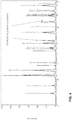
- FIG. 3 is a plot illustrating electrical conductivity measurements taken for (La 0.67 Sr 0.33 ) 0.97 (Mn 0.67 Ni 0.33 )O 3 in both air and a low oxygen partial pressure (1x10 -18 atm) . As illustrated, the electrical conductivity measurements showed conductivity in low pO 2 fuel of 3-4 S/cm at typical fuel cell operating temperatures.
- the composition was analyzed via X-ray diffraction.
- the X-ray diffraction showed the R-P phase, likely some minor residual perovskite phase, and Ni metal phase.
- FIG. 4 is a plot illustrating the results of the X-ray diffraction analysis of the reduced third example composition. As shown, the results indicate that Ni metal phase is present in the reduced composition (other lines are for R-P phase and there is very minor MnO present).
- the cathode was an LSM+YSZ composite
- the cathode current collector was 100% LSM of the same composition of the LSM in the cathode
- the anode current collector was a NiPd alloy cermet with YSZ and MgAl 2 O 4 ceramic phases.
- the active anodes for each of the three cells were as follows:
- FIG. 5 is a plot illustrating measured voltage versus current density for each of the three cells fabricated for evaluation. As shown, best performing cell was included B1:LSMN67+10Sc as the active anode with ASR in the 0.6 ohm-cm 2 range. Even though the ASR value is higher than traditional Ni-YSZ based anodes, the performance expects to be further improved through optimizing composition and microstructure. These result showed improved performance when compositing the Mn-based R-P and Ni phases with an ionic phase
Description
- This invention was made with Government support under Assistance Agreement No.
DE-FE0000303 - The disclosure generally relates to fuel cells, such as solid oxide fuel cells.
- Fuel cells, fuel cell systems and interconnects for fuel cells and fuel cell systems remain an area of interest. Some existing systems have various shortcomings, drawbacks, and disadvantages relative to certain applications. Accordingly, there remains a need for further contributions in this area of technology.
- Document
EP 1441 406 A2 discloses a fuel cell comprising an anode having a La(Sr)Cr(Mn)O3 perovskite as main component and including nickel.US 2011/091794 A1 discloses a fuel electrode comprising a perovskite represented by A1-xA'xB1-yB'yO3, wherein A can be La and A' Sr; B can Ti, and can be substituted by Ni (= B').US 2012/321983 A1 discloses a fuel cell comprising a cathode, an electrolyte, an anode, wherein the anode can be made of La1-xSrxMnyCr1-yO3. It refers to a Ruddlesden-Popper phase only in combination with a cathode. - Example compositions for anodes of fuels cells, such as, e.g., solid oxide fuels cells, are described. For example, a composition including a Ni metal phase constitution dispersed in a Mn-based Ruddlesden-Popper (R-P) phase constitution is used to form an anode for use in an electrochemical cell. When employed in a solid oxide fuel cell, an anode of such a composition may display relatively high durability in despite the relatively low oxygen partial pressure operating environment of the fuel side of the cell, e.g., due to the inherent thermodynamics of MnOx compounds and the size of the Mn cations. Moreover, the presence of Ni metal phase constitution dispersed within the R-P phase constitution may act as a fuel oxidizing catalyst in combination with the catalytic activity of the R-P phase constitution.
- In one example, the disclosure is directed to a fuel cell comprising a cathode; an electrolyte; and an reduced anode separated from the cathode by the electrolyte, wherein the reduced anode includes a Ni metal phase constitution dispersed in a (La1-xSrx)n+1MnnO3n+1 compound having a Mn-based Ruddlesden-Popper (R-P) phase constitution, wherein n is equal to or greater than one, and wherein the anode, cathode, and electrolyte are configured to form an electrochemical cell.
- In another example, the disclosure is directed to a method of making a fuel cell, the method comprising forming an electrolyte on adjacent an anode, wherein the electrolyte separates the anode from a cathode, wherein the anode includes a Ni metal phase constitution dispersed in a (La1-xSrx)n+1MnnO3n+1 compound having a Mn-based Ruddlesden-Popper (R-P) phase constitution, wherein n is equal to or greater than one , and wherein the anode, cathode, and electrolyte are configured to form an electrochemical cell.
- The Ni metal phase constitution dispersed in a (La1-xSrx)n+1MnnO3n+1 compound are formed from the reduction of a (La1-xSrx)(MnyNi1-y)O3 perovskite phase present during the initial processing of the anode under high oxygen partial pressure (air) firing conditions.
- The details of one or more embodiments of the disclosure are set forth in the accompanying drawings and the description below. Other features, objects, and advantages of the disclosure will be apparent from the description and drawings, and from the claims.
- The description herein makes reference to the accompanying drawings wherein like reference numerals refer to like parts throughout the several views.
-
FIG. 1 is a schematic diagram illustrating an example fuel cell system in accordance with an embodiment of the present disclosure. -
FIG. 2 is a schematic diagram illustrating an example cross section of a fuel cell system in accordance with an embodiment of the present disclosure. -
FIGS. 3-5 are plots illustrating properties of experimental examples in accordance with embodiments of the present disclosure. - Referring to the drawings, some aspects of a non-limiting example of a fuel cell system in accordance with an embodiment of the present disclosure is schematically depicted. In the drawing, various features, components and interrelationships therebetween of aspects of an embodiment of the present disclosure are depicted. However, the present disclosure is not limited to the particular embodiments presented and the components, features and interrelationships therebetween as are illustrated in the drawings and described herein.
- As described above, examples of the present disclosure relates to example compositions for anodes of fuels cells, such as, e.g., solid oxide fuels cells. For example, a composition including a Ni metal phase constitution dispersed in a Mn-based R-P phase constitution is used to form an anode for use in an electrochemical cell. When employed in a solid oxide fuel cell, an anode of such a composition may display relatively high durability in despite the relatively low oxygen partial pressure operating environment of the fuel side of the cell, e.g., due to thermodynamic equilibrium characteristics of MnOx compounds, and the size of the Mn cations are acceptable for the formation of the R-P phase. Moreover, the presence of Ni metal constitution dispersed within the R-P phase constitution may act as a fuel oxidizing catalyst in combination with the catalytic activity of the R-P phase constitution.
- A variety of compositions may be used to form the various components of a solid oxide fuel cell including anodes and cathodes. In some examples, cathodes formed of nickelate based R-P compounds may exhibit desirable electronic and catalytic properties. For example, it has been shown that nickelate based R-P compounds of the general formula Ren+1NinO3n+1 where Re is an element of La, Pr, Nd or Sm or combinations thereof may be used to form SOFC cathodes. Such compounds may have desirable mixed ionic and electronic conductivity properties that result in low cathode polarization resistances (e.g., relatively low area specific resistance, ASR). However, such nickelate-based R-P compounds may not be suitable in all cases as an anode material, e.g., as the low oxygen partial pressure of the fuel side in a fuel cell may result in phase decomposition of the anode material.
- Despite the limitations surrounding the use of nickelate R-P compounds, it has been determined that Mn-based nickelate R-P compounds may be suitable to form an anode of a fuel cell despite the low oxygen partial pressure of the fuel side in a fuel cell. For example, based on the thermodynamic equilibrium of MnOx compounds and the size of the Mn cations, Mn-based R-P compounds may be favored to exist under the low oxygen partial pressure of the fuel side in a fuel cell, and such an anode material may not be susceptible to the phase decomposition occurring for anodes formed from nickelate based R-P compounds. Whereas the nickel content of a nickelate R-P will be fully reduced to metallic nickel under the SOFC fuel environment, manganese content of oxide phase will tend to be reduced to Mn2+ and thus available to maintain a stable oxide phase under fuel environments. Accordingly, Mn-based R-P compounds (e.g., of the formula (La1-xSrx)+1MnnO3n+1), may be a suitable material for a ceramic anode, e.g., as an alternative to Ni-YSZ cermet based anodes, due to favorable mixed ionic and electronic conductivity and microstructure retention under redox cycles and overall durability of the ceramic. The order ("n" value) of the Mn-based R-P phase will most commonly be the lower ordered compounds (n=1 or 2) that require lower average valence states for the Mn, as under the low partial pressure conditions of the fuel environment, the valence state of Mn will tend towards Mn2+.
- One challenge in realizing a phase stable Mn-based R-P compound for an active anode (functioning in low oxygen partial pressure) is that it must first be processed in an air environment during the formation of the SOFC article, thus requiring a change in the Mn valence state and therefore affecting the stoichiometry and phase stability of the original oxide compound. In one example, an intermediate oxide phase is utilized that is stable under the standard air-firing conditions of SOFC, and that upon reduction generates a correct stoichiometric Mn-based R-P compound that is phase stable under the SOFC fuel environment based on achievement of suitable Mn valence states and A-to-B site ratios as the degree of A-site doping by cations such as Sr can influence the valence state of the Mn on the B-site. The option to achieve the Mn-based R-P phase under the fuel environment of the SOFC is to start with an air-stable, Mn and Ni mixed B-site perovskites, such as, e.g., (La1-xSrx)(Mn1-x,Nix)O3 anode formulation during air firing. Upon reduction, these compounds change to a Ni metal phase plus (La1-xSrx)n+1MnnO3n+1, which is a R-P compound that is most generally favored to exist under low oxygen partial pressure where Mn valence trends toward 2+. As an additional benefit, a Ni phase is produced during reduction that contributes catalytic properties in addition to the Mn-based R-P phase.
-
FIG. 1 is a schematic diagram illustrating an example fuel cell system 10 in accordance with an embodiment of the present disclosure. As shown inFIG. 1 , fuel cell system 10 includes a plurality of electrochemical cells 12 (or "individual fuel cells") formed on substrate 14. As will be described below, one or more of the plurality of electrochemical cells 12 may include an anode formed of the example compositions described herein. Electrochemical cells 12 are coupled together in series by interconnects 16. Fuel cell system 10 is a segmented-in-series arrangement deposited on a flat porous ceramic tube, although it will be understood that the present disclosure is equally applicable to segmented-in-series arrangements on other substrates, such on a circular porous ceramic tube. In various embodiments, fuel cell system 10 may be an integrated planar fuel cell system or a tubular fuel cell system. - Each electrochemical cell 12 includes an oxidant side 18 and a
fuel side 20. The oxidant is generally air, but could also be pure oxygen (O2) or other oxidants, e.g., including dilute air for fuel cell systems having air recycle loops, and is supplied to electrochemical cells 12 from oxidant side 18. Substrate 14 may be specifically engineered porosity, e.g., the porous ceramic material is stable at fuel cell operation conditions and chemically compatible with other fuel cell materials. In other embodiments, substrate 14 may be a surface-modified material, e.g., a porous ceramic material having a coating or other surface modification, e.g., configured to prevent or reduce interaction between electrochemical cell 12 layers and substrate 14. A fuel, such as a reformed hydrocarbon fuel, e.g., synthesis gas, is supplied to electrochemical cells 12 fromfuel side 20 via channels (not shown) in porous substrate 14. Although air and synthesis gas reformed from a hydrocarbon fuel may be employed in some examples, it will be understood that electrochemical cells using other oxidants and fuels may be employed without departing from the scope of the present disclosure, e.g., pure hydrogen and pure oxygen. In addition, although fuel is supplied to electrochemical cells 12 via substrate 14, it will be understood that in other embodiments, the oxidant may be supplied to the electrochemical cells via a porous substrate. -
FIG. 2 is a schematic diagram illustrating an example cross section of fuel cell system 10 in accordance with an embodiment of the present disclosure. Fuel cell system 10 may be formed of a plurality of layers screen printed onto substrate 14. This may include a process whereby a woven mesh has openings through which the fuel cell layers are deposited onto substrate 14. The openings of the screen determine the length and width of the printed layers. Screen mesh, wire diameter, ink solids loading and ink rheology may determine the thickness of the printed layers. Fuel cell system 10 layers include an anode conductive layer 22, an anode layer 24, an electrolyte layer 26, a cathode layer 28 and acathode conductive layer 30. In one form, electrolyte layer 26 may be a single layer or may be formed of any number of sub-layers. It will be understood thatFIG. 2 is not necessarily to scale. For example, vertical dimensions are exaggerated for purposes of clarity of illustration. - In each electrochemical cell 12, anode conductive layer 22 conducts free electrons away from anode 24 and conducts the electrons to
cathode conductive layer 30 via interconnect 16. Cathodeconductive layer 30 conducts the electrons to cathode 28. Interconnect 16 is embedded in electrolyte layer 26, and is electrically coupled to anode conductive layer 22, and extends in direction 32 from anode conductive layer 22 through electrolyte layer 26, then in direction 36 from one electrochemical cell 12 to the next adjacent electrochemical cell 12, and then in direction 32 again towardcathode conductive layer 30, to which interconnect 16 is electrically coupled. In particular, at least a portion of interconnect 16 is embedded within an extended portion of electrolyte layer 26, wherein the extended portion of electrolyte layer 26 is a portion of electrolyte layer 26 that extends beyond anode 24 and cathode 28, e.g., in direction 32, and is not sandwiched between anode 24 and cathode 28. - Interconnects 16 for solid oxide fuel cells (SOFC) are preferably electrically conductive in order to transport electrons from one electrochemical cell to another; mechanically and chemically stable under both oxidizing and reducing environments during fuel cell operation; and nonporous, in order to prevent diffusion of the fuel and/or oxidant through the interconnect. If the interconnect is porous, fuel may diffuse to the oxidant side and burn, resulting in local hot spots that may result in a reduction of fuel cell life, e.g., due to degradation of materials and mechanical failure, as well as reduced efficiency of the fuel cell system. Similarly, the oxidant may diffuse to the fuel side, resulting in burning of the fuel. Severe interconnect leakage may significantly reduce the fuel utilization and performance of the fuel cell, or cause catastrophic failure of fuel cells or stacks.
- For segmented-in-series cells, fuel cell components may be formed by depositing thin films on a porous ceramic substrate, e.g., substrate 14. In one form, the films are deposited via a screen printing process, including the interconnect. In other embodiments, other process may be employed to deposit or otherwise form the thin films onto the substrate. The thickness of interconnect layer may be 5 to 30 microns, but can also be much thicker, e.g., 100 microns.
- Interconnect 16 may be formed of a precious metal including Ag, Pd, Au and/or Pt and/or alloys thereof, although other materials may be employed without departing from the scope of the present disclosure. For example, in other embodiments, it is alternatively contemplated that other materials may be employed, including precious metal alloys, such as Ag-Pd, Ag-Au, Ag-Pt, Au-Pd, Au-Pt, Pt-Pd, Ag-Au-Pd, Ag-Au-Pt, Ag-Au-Pd-Pt and/or binary, ternary, quaternary alloys in the Pt-Pd-Au-Ag family, inclusive of alloys having minor non-precious metal additions, cermets composed of a precious metal, precious metal alloy, and an inert ceramic phase, such as alumina, or ceramic phase with minimum ionic conductivity which will not create significant parasitics, such as YSZ (yttria stabilized zirconia, also known as yttria doped zirconia, yttria doping is 3-8 mol%, preferably 3-5 mol%), ScSZ (scandia stabilized zirconia, scandia doping is 4-10 mol%, preferably 4-6 mol%), doped ceria, and/or conductive ceramics, such as conductive perovskites with A or B-site substitutions or doping to achieve adequate phase stability and/or sufficient conductivity as an interconnect, e.g., including at least one of doped strontium titanate (such as LaxSr1-xTiO3-δ, x=0.1 to 0.3), LSCM (La1-xSrxCr1-yMnyO3, x=0.1 to 0.3 and y=0.25 to 0.75), doped yttrium chromites (such as Y1-xCaxCrO3-δ, x=0.1-0.3) and/or other doped lanthanum chromites (such as La1-xCaxCrO3-δ, where x=0.15-0.3), and conductive ceramics, such as doped strontium titanate, doped yttrium chromites, LSCM (La1-xSrxCr1-yMnyO3), and other doped lanthanum chromites. In one example, interconnect 16 may be formed of y(PdxPt1-x)-(1-y)YSZ. Where x is from 0 to 1 in weight ratio, preferably x is in the range of 0 to 0.5 for lower hydrogen flux. Y is from 0.35 to 0.80 in volume ratio, preferably y is in the range of 0.4 to 0.6.
- Anode conductive layer 22 may be an electrode conductive layer formed of a nickel cermet, such as such as Ni-YSZ (e.g., where yttria doping in zirconia is 3-8 mol%,), Ni-ScSZ (e.g., where scandia doping is 4-10 mol%, preferably including a second doping for example 1 mol% ceria for phase stability for 10 mol% scandia-ZrO2) and/or Ni-doped ceria (such as Gd or Sm doping), doped lanthanum chromite (such as Ca doping on A site and Zn doping on B site), doped strontium titanate (such as La doping on A site and Mn doping on B site), La1-x SrxMnyCr1-yO3 and/or Mn-based R-P phases of the general formula a (La1-xSrx)n+1MnnO3n+1 Alternatively, it is considered that other materials for anode conductive layer 22 may be employed such as cermets based in part or whole on precious metal. Precious metals in the cermet may include, for example, Pt, Pd, Au, Ag, and/or alloys thereof. The ceramic phase may include, for example, an inactive non-electrically conductive phase, including, for example, YSZ, ScSZ and/or one or more other inactive phases, e.g., having desired coefficients of thermal expansion (CTE) in order to control the CTE of the layer to match the CTE of the substrate and electrolyte. In some embodiments, the ceramic phase may include Al2O3 and/or a spinel such as NiAl2O4, MgAl2O4, MgCr2O4, NiCr2O4. In other embodiments, the ceramic phase may be electrically conductive, e.g., doped lanthanum chromite, doped strontium titanate and/or one or more forms of LaSrMnCrO and/or R-P phases of the general formula (La1-xSrx)n+1MnnO3n+1
- Electrolyte layer 26 may be made from a ceramic material. In one form, a proton and/or oxygen ion conducting ceramic, may be employed. In one form, electrolyte layer 26 is formed of YSZ, such as 3YSZ and/or 8YSZ. In other embodiments, electrolyte layer 26 may be formed of ScSZ, such as 4ScSZ, 6ScSz and/or 10Sc1CeSZ in addition to or in place of YSZ. In other embodiments, other materials may be employed. For example, it is alternatively considered that electrolyte layer 26 may be made of doped ceria and/or doped lanthanum gallate. In any event, electrolyte layer 26 is substantially impervious to diffusion therethrough of the fluids used by fuel cell 10, e.g., synthesis gas or pure hydrogen as fuel, as well as, e.g., air or 02 as an oxidant, but allows diffusion of oxygen ions or protons.
- Cathode layer 28 may be formed at least one of of LSM (La1-xSrxMnO3, where x=0.1 to 0.3), La1-xSrxFeO3,(such as where x=0.3), La1-xSrxCoyFe1-yO3 (such as La0.6Sr0.4Co0.2 Fe0.8O3) and/or Pr1-xSrxMnO3 (such as Pr0.8Sr0.2MnO3), although other materials may be employed without departing from the scope of the present invention. For example, it is alternatively considered that Ruddlesden-Popper nickelates and La1-xCaxMnO3 (such as La0.8Ca0.2MnO3) materials may be employed.
- Cathode
conductive layer 30 may be an electrode conductive layer formed of a conductive ceramic, for example, at least one of LaNixFe1-xO3 (such as, e.g., LaNi0.6Fe0.4O3), La1-xSrxMnO3 (such as La0.75Sr0.25MnO3), and/or Pr1-xSrxCoO3, such as Pr0.8Sr0.2CoO3. In other embodiments,cathode conductive layer 30 may be formed of other materials, e.g., a precious metal cermet, although other materials may be employed without departing from the scope of the present invention. The precious metals in the precious metal cermet may include, for example, Pt, Pd, Au, Ag and/or alloys thereof. The ceramic phase may include, for example, YSZ, ScSZ and Al2O3, or other non-conductive ceramic materials as desired to control thermal expansion. - In accordance with one or more examples of the present disclosure, anode 24 may include a Mn-based nickelate R-P phase composition. In particular, anode 24 includes a Ni phase constitution and a (La1-xSrx)n+1MnnO3n+1 compound having a Mn-based R-P phase constitution, wherein n is equal to or greater than zero. As noted above, based on MnOx thermodynamics and the size of the Mn cations, Mn-based R-P compounds may be favored to exist under the low oxygen partial pressure of the fuel side in a fuel cell. An example range of oxygen partial pressures throughout the operation of a solid oxide fuel cell are from 10-17 atm (stack outlet fuel composition) to 10-20 atm representative of an anode protection gas mixture of H2/N2 containing some H2O as a result of parasitic currents. Such an anode material may not be susceptible to the phase decomposition occurring for anodes formed from La-based nickelate R-P compounds, while still exhibiting desirable electronic and catalytic properties. Further, the presence of Ni phase constitution dispersed within the R-P phase constitution may act as a fuel oxidizing catalyst in combination with the catalytic activity of the R-P phase constitution.
- The nickelate R-P composition of anode 24 may be formed using any suitable technique. In some examples, to form the Mn-based nickelate R-P composition of anode 24, the initial starting powder is a Mn and Ni mixed B-site perovskites, such as, e.g., (La1-xSrx)(MnyNi1-y)O3 may be utilized during air firing in the initial processing step of applying the anode precursor within the fuel cell structure. In some case, mixed B-site perovskites of the general formula (La1-xSrx)(MnyNi1-y)O3 may be used. Upon reduction in a fuel environment, these compounds change to a (La1-xSrx)n+1MnnO3n+1, where n is equal to or greater than one, which is a R-P compound plus residual Ni metal phase. As noted herein, the finely dispersed Ni phase may act as a fuel oxidizing catalyst in combination with the catalytic activity of the Mn-based R-P phase. Both the Mn-based R-P phase and Ni phases may contribute to the electronic conductivity needed for an active anode.
- Various other A-site and B-site cations may be included in the initial perovskite starting powder, for instance Ca and Pr for the A-site and various B-site dopants such as Cu and Co that may be minimally retained in the R-P structure on reduction, but which may most preferentially be alloyed with the Ni alloy phase. Additional Ni content can be incorporated into the resulting anode by the addition of NiO with the (La1-xSrx)(MnyNi1-y)O3 powder within the processing of the anode into the fuel cell structure.
- There is the potential to in-situ form a Mn plus Ni mixed B-site R-P compound during initial anode firing by mixing of (La1-xSrx)MnO3 and R-P nickelate, (La1-xSrx)n+1NinO3n+1, by selecting the correct molar ratios of A-site and B-site cations in the two powders and the correct molar ratio of the two powders. Upon reduction a Mn-based R-P phase constitution in addition to a dispersed Ni phase can result. For example:
2(La1-xSrx)(Mn)O3 + (La1-xSrx)2NiO4 → (La1-xSrx)4(Mn2Ni)O10 (air) Ni + 2(La1-xSrx)2MnO4 (reduced)
- Where higher ordered (e.g., n=2,3) Mn-based R-P phases may be able to be formed in air because of the higher required B-site valence state in such compounds, and where these compounds could be mixed with NiO such that there could be an in-situ reaction during anode processing forming a mixed Ni and Mn B-site higher ordered R-P compound stable in air. With careful selection of chemistry and stoichiometry, upon reduction a Mn-based R-P phase constitution in addition to a dispersed Ni phase can result. Alternatively, the mixed Ni and Mn B-site higher ordered R-P compound could be the actual starting composition of the powder rather than formed in-situ. For example:
Ex. 1/3 NiO + 4/3 (La1-xSrx)3Mn2O7 → (La1-xSrx)4(Mn2.67Ni0.33)O10 (air) Ni + (La1-xSrx)3Mn2O4 (reduced)
- Other combinations of starting compounds are possible with the end objective of achieving a Mn-based R-P phase constitution in addition to a dispersed Ni phase upon anode reduction. Limitations on processing routes may exist based on the inability to achieve stable mixed B-site Mn-Ni R-P phases stable in air, but these examples are illustrative as potential routes to forming the desired anode phases.
- The composition of anode 24 may be such that substantially all of anode 24 is formed of a (La1-xSrx)n+1MnnO3n+1 compound having a Mn-based R-P phase constitution in addition to Ni phase dispersed in the (La1-xSrx)n+1MnnO3n+1 compound. For example, anode 24 may include at least 80 wt% of the (La1-xSrx)n+1MnnO3n+1 compound having a Mn-based R-P phase constitution, such as, e.g., at least 82 wt% (La1-xSrx)n+1MnnO3n+1 compound having a Mn-based Ruddlesden-Popper (R-P) phase constitution. An example is (La0.75Sr0.25)(Mn0.5Ni0.5)O3 which upon reduction leads to 83.1% (La0.75Sr0.25)2MnO4 and 16.9% Ni.
- The nickel phase may be present along with the (La1-xSrx)n+1MnnO3n+1 compound in an amount that allows for the Ni to act as a fuel oxidizing catalyst in combination with the catalytic activity of the R-P phase constitution. For example, anode 24 may include approximately 5 to approximately 18 percent by weight, As an example, (La0.75Sr0.25)(Mn0.5Ni0.5)O3 which upon reduction leads to 83.1% (La0.75Sr0.25)2MnO4 and 16.9% Ni at one end of the range (n=1 order) and (La0.75Sr0.25)(Mn0.75Ni0.25)O3 which upon reduction leads to 93.2% (La0.75Sr0.25)4Mn3O4 and 6.8% Ni (for n=3 order), and at higher order R-P compounds the Ni content would be less. The prior examples are indicative of Ni contents that could be achieve from dissolution from the perovskite phase upon reduction, but additional Ni content may be achieved by including NiO content along with the (La1-xSrx)(MnyNi1-y)O3 during the initial processing of the anode.
- Although it may be desirable to achieve phase pure B-site mixed perovskite or R-P phases during the initial air-sintering of the anode and likewise upon reduction to achieve only the desired R-P phase plus Ni constitution, it is realized that some secondary phases from incomplete reactions during powder synthesis or in-situ formulation may result and that some minor phases other than the R-P and Ni phases may occur upon reduction because of incomplete phase decomposition, however, the presence of minor amounts of these phases may still provide for favorable performance and durability of the solid oxide fuel cell.
- In cases in which the anode composition is formed via the reduction of Mn and Ni mixed B-site perovskites, the amount of Ni phase dispersed in the Mn-based R-P may depend on the composition of the Mn and Ni mixed B-site perovskites. In particular, the ratio of the Mn to Ni content on the B-site of the perovskite composition will dictate the nature of the resulting Mn-based R-P compound. As an example, the below table illustrate theoretical composition resulting from the reduction of Mn and Ni mixed B-site perovskites.
Mn fraction (y) on B-site 0.5 0.67 0.75 Theoretical resulting Mn R-P compound on reduction (La1-xSrx)2MnO3 (La1-xSrx)3Mn2O7 (La1-xSrx)4Mn3O10 Order of R-P phase 1 2 3 - The perovskite composition does not necessarily need to be at 0.5. 0.67 and 0.75. Values for the Mn fraction on the B-site different from 0.5. 0.67 and 0.75 would be expected to yield combinations of different ordered R-P compositions,. The relative levels of free metallic Ni in the reduced anode would be greatest for perovskite Mn volume fractions at about 0.5. As there could be some remaining solubility of Ni within the ceramic phase upon reduction, the resulting R-P phase may have some mixed Mn and Ni on the B-site, there could be some remaining perovskite phase present and the final metallic Ni phase would thus be less than theoretical phases along with any residual perovskite phases.
- In some examples, the composition of anode 24 may include one or more additives, elements, or compounds other than Ni phase dispersed in the (La1-xSrx)n+1MnnO3n+1 compound having a Mn-based R-P phase constitution. In one example, the Ni plus (La1-xSrx)n+1MnnO3n+1 Mn-based R-P phases may be composited with an ionic phase such as 8YSZ, or yttria stabilized zirconias (YSZ) of 3-8 mole percent yttria, scandia stabilized zirconia (ScSZ) of 4-10 mole percent scandia and may include minor additional stabilizers such as 1 mole percent Ce or 0.5-1 mole percent alumina, and may include doped ceria where the dopant is one or more of Gd, Y, Sm and/or Pr. In such an embodiment, the starting mixture for the anode consists of the (La1-xSrx)(MnyNi1-y)O3, the ionic phase and could include additional NiO content as desired to impact polarization resistance and bulk electronic conductivity of the reduced anode. In one example, anode 24 may consist essentially of Ni and the the (La1-xSrx)n+1MnnO3n+1 compound having a Mn-based R-P phase constitution, where the additionally material in present only in an amount that does not alter one or more properties of the material in a manner that does not allow anode 24 to function as described herein.
- As noted above, anode conductive layer 22 may be an electrode conductive layer formed of a nickel cermet. Since in some examples, predominately ceramic-based anodes, including those described herein, may provide for a relatively low polarization ASR, however the electronic conductivity in some instances may be insufficient. Accordingly, anode conductive layer 22 may be a Ni-based cermet composition to account for the low electronic conductivity of anode 24.
- Any suitable technique may be employed to form electrochemical cell 12 of
FIGS. 1 and2 . In the example ofFIG. 2 , anode conductive layer 22 may be printed directly onto substrate 14, as is a portion of electrolyte 26. Anode layer 24 may be printed onto anode conductive layer 22. Portions of electrolyte layer 26 may be printed onto anode layer 24, and portions of electrolyte layer 26 are printed onto anode conductive layer 22 and onto substrate 14. Cathode layer 28 is printed on top of electrolyte layer 26. Portions ofcathode conductive layer 30 are printed onto cathode layer 28 and onto electrolyte layer 26. Cathode layer 28 is spaced apart from anode layer 24 in a direction 32 by the local thickness of electrolyte layer 26. - Anode layer 24 includes anode gaps 34, which extend in a direction 36. Cathode layer 28 includes cathode gaps 38, which also extend in direction 36. In the example of
FIG. 2 , direction 36 is substantially perpendicular to direction 32, although the present disclosure is not so limited. Gaps 34 separate anode layer 24 into a plurality of individual anodes 40, one for each electrochemical cell 12. Gaps 38 separate cathode layer 28 into a corresponding plurality of cathodes 42. Each anode 40 and the corresponding cathode 42 that is spaced apart in direction 32 therefrom, in conjunction with the portion of electrolyte layer 26 disposed therebetween, form an electrochemical cell 12. - Similarly, anode conductive layer 22 and
cathode conductive layer 30 have respective gaps 44 and 46 separating anode conductive layer 22 andcathode conductive layer 30 into a plurality of respective anode conductor films 48 and cathode conductor films 50. The terms, "anode conductive layer" and "anode conductor film" may be used interchangeably, in as much as the latter is formed from one or more layers of the former; and the terms, "cathode conductive layer" and "cathode conductor film" may be used interchangeably, in as much as the latter is formed from one or more layers of the former. - In some examples, anode conductive layer 22 has a thickness, i.e., as measured in direction 32, of approximately 5-15 microns, although other values may be employed without departing from the scope of the present disclosure. For example, it is considered that in other embodiments, the anode conductive layer may have a thickness in the range of approximately 5-50 microns. In yet other embodiments, different thicknesses may be used, e.g., depending upon the particular material and application.
- Similarly, anode layer 24 may have a thickness, i.e., as measured in direction 32, of approximately 5-20 microns, although other values may be employed without departing from the scope of the present invention. For example, it is considered that in other embodiments, the anode layer may have a thickness in the range of approximately 5-40 microns. In yet other embodiments, different thicknesses may be used, e.g., depending upon the particular anode material and application.
- Electrolyte layer 26 may have a thickness of approximately 5-15 microns with individual sub-layer thicknesses of approximately 5 microns minimum, although other thickness values may be employed without departing from the scope of the present invention. For example, it is considered that in other embodiments, the electrolyte layer may have a thickness in the range of approximately 5-40 microns. In yet other embodiments, different thicknesses may be used, e.g., depending upon the particular materials and application.
- Cathode layer 28 has a thickness, i.e., as measured in direction 32, of approximately 10-20 microns, although other values may be employed without departing from the scope of the present invention. For example, it is considered that in other embodiments, the cathode layer may have a thickness in the range of approximately 10-50 microns. In yet other embodiments, different thicknesses may be used, e.g., depending upon the particular cathode material and application.
- Cathode
conductive layer 30 has a thickness, i.e., as measured in direction 32, of approximately 5-100 microns, although other values may be employed without departing from the scope of the present invention. For example, it is considered that in other embodiments, the cathode conductive layer may have a thickness less than or greater than the range of approximately 5-100 microns. In yet other embodiments, different thicknesses may be used, e.g., depending upon the particular cathode conductive layer material and application. - Although not shown in
FIG. 2 , in some examples, fuel cell system 10 may include one or more chemical barrier layers between interconnect 16 and adjacent components to reduce or prevent diffusion between the interconnect and adjacent components, e.g., an anode and/or an anode conductor film and/or cathode and/or cathode conductor film, may adversely affect the performance of certain fuel cell systems. In various embodiments, such a chemical barrier layer may be configured to prevent or reduce material migration or diffusion at the interface between the interconnect and an anode, and and/or between the interconnect and an anode conductor film, and/or between the interconnect and a cathode, and/or between the interconnect and a cathode conductor film which may improve the long term durability of the interconnect. For example, without a chemical barrier, material migration (diffusion) may take place at the interface between an interconnect formed of a precious metal cermet, and an anode conductor film and/or anode formed of a Ni-based cermet. The material migration may take place in both directions, e.g., Ni migrating from the anode conductive layer/conductor film and/or anode into the interconnect, and precious metal migrating from the interconnect into the conductive layer/conductor film and/or anode. The material migration may result in increased porosity at or near the interface between the interconnect and the anode conductor film and/or anode, and may result in the enrichment of one or more non or low-electronic conducting phases at the interface, yielding a higher area specific resistance (ASR), and hence resulting in reduced fuel cell performance. Material migration between the interconnect and the cathode and/or between the interconnect and the cathode conductor film may also or alternatively result in deleterious effects on fuel cell performance. Such a chemical barrier layer may be formed of one or both of two classes of materials; cermet and/or conductive ceramic. - Various experiments were carried out to evaluate one or more aspects of example anode compositions in accordance with the disclosure. However, examples of the disclosure are not limited to the experimental anode compositions.
- Three different Mn+Ni B-site perovskite powders where obtained from TransTech, Inc. (Adamstown, MD). In particular, the first example powder obtained was (La0.875Sr 0.125)(Mn0.5Ni 0.5)O3, which was designed to form (La0.875Sr 0.125)2MnO4 n=1 ordered R-P phase constitution plus Ni metal phase constitution on reduction. After reduction, the composition was analyzed via X-ray diffraction. The X-ray diffraction showed some R-P phase, perovskite phase, metallic Ni phase and some free La2O3. Based on the La2O3 content, it was determined that the example composition was not favorable for the desired phase generation.
- The second example powder obtained for evaluation was (La0.67Sr 0.33)0.97(Mn0.67Ni 0.33)O3, which was designed to form (La0.67Sr 0.33)2.91Mn2O7 n=2 ordered R-P phase constitution (with slight A-site deficiency) plus Ni metal phase constitution on reduction. After reduction, the composition was analyzed via X-ray diffraction. The X-ray diffraction showed the R-P phase and Ni metal phase.
FIG. 3 is a plot illustrating electrical conductivity measurements taken for (La0.67Sr 0.33)0.97(Mn0.67Ni 0.33)O3 in both air and a low oxygen partial pressure (1x10-18 atm) . As illustrated, the electrical conductivity measurements showed conductivity in low pO2 fuel of 3-4 S/cm at typical fuel cell operating temperatures. - The third example powder obtained for evaluation was (La0.45Sr 0.55)0.97(Mn0.5Ni 0.5)O3, which was designed to form (La0.45Sr 0.55)1.94MnO4 n=1 ordered R-P phase constitution (with slight A-site deficiency) plus Ni metal phase constitution on reduction. After reduction, the composition was analyzed via X-ray diffraction. The X-ray diffraction showed the R-P phase, likely some minor residual perovskite phase, and Ni metal phase.
FIG. 4 is a plot illustrating the results of the X-ray diffraction analysis of the reduced third example composition. As shown, the results indicate that Ni metal phase is present in the reduced composition (other lines are for R-P phase and there is very minor MnO present). - Three individual electrochemical fuel cells were fabricated using the second and third example powder compositions to form anodes for the cells. For these cells the cathode was an LSM+YSZ composite, the cathode current collector was 100% LSM of the same composition of the LSM in the cathode, the anode current collector was a NiPd alloy cermet with YSZ and MgAl2O4 ceramic phases.. In particular, the active anodes for each of the three cells were as follows:
- (La0.45Sr 0.55)0.97(Mn0.5Ni 0.5)O3 (referred to as B2:LSMN50).
- (La0.67Sr0.33)0.97(Mn0.67Ni 0.33)O3 plus 10Sc1CeSZ ionic phase (referred to as B1:LSMN67+10Sc)
- (La0.45Sr 0.55)0.97(Mn0.5Ni 0.5)O3 plus 10Sc1CeSZ ionic phase (referred to as A2:LSMN50+10Sc).
-
FIG. 5 is a plot illustrating measured voltage versus current density for each of the three cells fabricated for evaluation. As shown, best performing cell was included B1:LSMN67+10Sc as the active anode with ASR in the 0.6 ohm-cm2 range. Even though the ASR value is higher than traditional Ni-YSZ based anodes, the performance expects to be further improved through optimizing composition and microstructure. These result showed improved performance when compositing the Mn-based R-P and Ni phases with an ionic phase - Various embodiments of the invention have been described. These and other embodiments are within the scope of the following claims.
Claims (14)
- A fuel cell comprising:a cathode;an electrolyte; anda reduced anode separated from the cathode by the electrolyte, wherein the reduced anode includes a Ni metal phase constitution dispersed in a (La1-xSrx)n+1MnnO3n+1 compound having a Mn-based Ruddlesden-Popper (R-P) phase constitution, wherein n is equal to or greater than one, and wherein the anode, cathode, and electrolyte are configured to form an electrochemical cell.
- The fuel cell of claim 1, wherein the Ni metal phase constitution dispersed in the (La1-xSrx)n+1MnnO3n+1 compound having a Mn-based R-P phase constitution, of n greater than or equal to 1, is formed via a reduction of a Mn and Ni mixed B-site compound having a perovskite structure or Ruddlesden-Popper compound that is present following an initial anode processing step.
- The fuel cell of claim 2, wherein the Mn and Ni mixed B-site compound comprises a (La1-xSrx)(Mn1-xNix)O3 compound.
- The fuel cell of claim 2, wherein the Mn and Ni mixed B-site compound comprises a (La1-xSrx)n+1(Ni1-xMnx)nO3n+1 Ruddlesden-Popper compound.
- The fuel cell of claim 1, wherein the reduced anode includes between approximately 82 and approximately 95 wt% of the (La1-xSrx)n+1MnnO3n+1 compound having the Mn-based R-P phase constitution and between 5-18 wt% of the Ni metal phase constitution.
- The fuel cell of claim 1, wherein the reduced anode further includes an ionic phase including yttria and/or scandia stabilized zirconia or rare-earth oxide stabilized ceria dispersed in the Ni metal phase and (La1-xSrx)n+1MnnO3n+1 Mn-based R-P phase, wherein the ionic phase is present in an amount of 35 weight percent to 65 weight percent.
- The fuel cell of claim 1, wherein the anode consists essentially of the Ni metal phase constitution dispersed in the (La1-xSrx)n+1MnnO3n+1 compound having the Mn-based R-P phase constitution.
- A method for forming a fuel cell, the fuel cell including:a cathode;an electrolyte; anda reduced anode separated from the cathode by the electrolyte;the method comprising:forming an initial anode in an air environment, wherein the initial anode comprises a Mn and Ni mixed B-site compound having a perovskite structure or a Ruddlesden-Popper compound when initially formed; andreducing the Mn and Ni mixed B-site compound having a perovskite structure or a Ruddlesden-Popper compound in a fuel environment to form a reduced anode;wherein the composition of the initial anode is such that the reduced anode includes a Ni metal phase constitution dispersed in a (La1-xSrx)n+1MnnO3n+1 compound having a Mn-based Ruddlesden-Popper (R-P) phase constitution, wherein n is equal to or greater than one, and wherein the anode, cathode, and electrolyte are configured to form an electrochemical cell.
- The method of claim 8, wherein the Mn and Ni mixed B-site compound comprises a (La1-xSrx)(Mn1-xNix)O3 compound.
- The method of claim 8, wherein the Mn and Ni mixed B-site compound comprises a (La1-xSrx)n+1(Ni1-xMnx)nO3n+1 Ruddlesden-Popper compound.
- The method of claim 8, wherein the reduced anode includes between 82 and 95 wt% of the (La1-xSrx)n+1MnnO3n+1 compound having the Mn-based R-P phase constitution and between 5-18 wt% of the Ni metal phase.
- The method of claim 8, further comprising adding an ionic phase including yttria and/or scandia stabilized zirconia or rare-earth oxide stabilized ceria to the Ni metal phase and (La1-xSrx)n+1MnnO3n+1 Mn-based R-P phase, wherein the reduced anode includes the ionic phase in an amount of 35 weight percent to 65 weight percent.
- The method of claim 8, wherein the reduced anode consists essentially of the Ni metal phase constitution and the (La1-xSrx)n+1MnnO3n+1 compound having the Mn-based R-P phase constitution.
- The method of claim 8, further comprising forming an anode conductive layer adjacent the anode, wherein the anode conductive layer comprises a cermet, where the metal phase in the cermet comprises Ni.
Applications Claiming Priority (2)
| Application Number | Priority Date | Filing Date | Title |
|---|---|---|---|
| US13/837,068 US20140272672A1 (en) | 2013-03-15 | 2013-03-15 | Composition for anode in fuel cell |
| PCT/US2014/022059 WO2014150060A1 (en) | 2013-03-15 | 2014-03-07 | Composition for anode in fuel cell |
Publications (2)
| Publication Number | Publication Date |
|---|---|
| EP2973807A1 EP2973807A1 (en) | 2016-01-20 |
| EP2973807B1 true EP2973807B1 (en) | 2017-11-29 |
Family
ID=50346190
Family Applications (1)
| Application Number | Title | Priority Date | Filing Date |
|---|---|---|---|
| EP14712168.5A Active EP2973807B1 (en) | 2013-03-15 | 2014-03-07 | Composition for anode in fuel cell |
Country Status (10)
| Country | Link |
|---|---|
| US (1) | US20140272672A1 (en) |
| EP (1) | EP2973807B1 (en) |
| KR (1) | KR20150129017A (en) |
| CN (1) | CN105580176B (en) |
| AU (1) | AU2014237586B2 (en) |
| CA (1) | CA2906355A1 (en) |
| DK (1) | DK2973807T3 (en) |
| ES (1) | ES2652540T3 (en) |
| SG (1) | SG11201507653YA (en) |
| WO (1) | WO2014150060A1 (en) |
Families Citing this family (2)
| Publication number | Priority date | Publication date | Assignee | Title |
|---|---|---|---|---|
| JP7417224B2 (en) * | 2020-01-31 | 2024-01-18 | Eneos株式会社 | Hydrogen production method, carbon monoxide production method and reaction medium |
| CN113136621A (en) * | 2021-04-21 | 2021-07-20 | 南京大学 | Layered nickel oxide with high-efficiency catalytic activity and preparation method thereof |
Family Cites Families (4)
| Publication number | Priority date | Publication date | Assignee | Title |
|---|---|---|---|---|
| US7291417B2 (en) * | 2003-01-16 | 2007-11-06 | Hewlett-Packard Development Company, L.P. | Compositional and structural gradients for fuel cell electrode materials |
| FR2930075B1 (en) * | 2008-04-14 | 2011-03-18 | Commissariat Energie Atomique | TITANATES OF PEROVSKITE OR DERIVED STRUCTURE AND ITS APPLICATIONS |
| KR101761346B1 (en) * | 2009-10-16 | 2017-07-25 | 인하대학교 산학협력단 | Fuel electrode material and solid oxide fuel cells using composite |
| US9105880B2 (en) * | 2011-06-15 | 2015-08-11 | Lg Fuel Cell Systems Inc. | Fuel cell system with interconnect |
-
2013
- 2013-03-15 US US13/837,068 patent/US20140272672A1/en not_active Abandoned
-
2014
- 2014-03-07 SG SG11201507653YA patent/SG11201507653YA/en unknown
- 2014-03-07 EP EP14712168.5A patent/EP2973807B1/en active Active
- 2014-03-07 CN CN201480024585.9A patent/CN105580176B/en not_active Expired - Fee Related
- 2014-03-07 KR KR1020157029381A patent/KR20150129017A/en not_active Application Discontinuation
- 2014-03-07 ES ES14712168.5T patent/ES2652540T3/en active Active
- 2014-03-07 DK DK14712168.5T patent/DK2973807T3/en active
- 2014-03-07 AU AU2014237586A patent/AU2014237586B2/en not_active Ceased
- 2014-03-07 WO PCT/US2014/022059 patent/WO2014150060A1/en active Application Filing
- 2014-03-07 CA CA2906355A patent/CA2906355A1/en not_active Abandoned
Also Published As
| Publication number | Publication date |
|---|---|
| AU2014237586B2 (en) | 2017-12-14 |
| CA2906355A1 (en) | 2014-09-25 |
| AU2014237586A1 (en) | 2015-10-08 |
| CN105580176B (en) | 2019-04-02 |
| DK2973807T3 (en) | 2018-01-02 |
| CN105580176A (en) | 2016-05-11 |
| US20140272672A1 (en) | 2014-09-18 |
| SG11201507653YA (en) | 2015-10-29 |
| WO2014150060A1 (en) | 2014-09-25 |
| EP2973807A1 (en) | 2016-01-20 |
| ES2652540T3 (en) | 2018-02-05 |
| KR20150129017A (en) | 2015-11-18 |
Similar Documents
| Publication | Publication Date | Title |
|---|---|---|
| US10003083B2 (en) | Composition for fuel cell electrode | |
| EP2721667B1 (en) | Fuel cell system with interconnect | |
| US10062909B2 (en) | Composition for fuel cell electrode | |
| EP2721669B1 (en) | Fuel cell system with interconnect | |
| EP2936596B1 (en) | Fuel cell system with interconnect | |
| US20130122393A1 (en) | Fuel cell system with interconnect | |
| EP2721680B1 (en) | Fuel cell system with interconnect | |
| EP2973810B1 (en) | Fuel cell system including multilayer interconnect | |
| EP2973807B1 (en) | Composition for anode in fuel cell |
Legal Events
| Date | Code | Title | Description |
|---|---|---|---|
| PUAI | Public reference made under article 153(3) epc to a published international application that has entered the european phase |
Free format text: ORIGINAL CODE: 0009012 |
|
| 17P | Request for examination filed |
Effective date: 20150911 |
|
| AK | Designated contracting states |
Kind code of ref document: A1 Designated state(s): AL AT BE BG CH CY CZ DE DK EE ES FI FR GB GR HR HU IE IS IT LI LT LU LV MC MK MT NL NO PL PT RO RS SE SI SK SM TR |
|
| AX | Request for extension of the european patent |
Extension state: BA ME |
|
| DAX | Request for extension of the european patent (deleted) | ||
| GRAP | Despatch of communication of intention to grant a patent |
Free format text: ORIGINAL CODE: EPIDOSNIGR1 |
|
| RIC1 | Information provided on ipc code assigned before grant |
Ipc: H01M 8/124 20160101ALN20170529BHEP Ipc: H01M 4/86 20060101AFI20170529BHEP Ipc: H01M 4/88 20060101ALI20170529BHEP Ipc: H01M 4/90 20060101ALI20170529BHEP |
|
| INTG | Intention to grant announced |
Effective date: 20170623 |
|
| GRAS | Grant fee paid |
Free format text: ORIGINAL CODE: EPIDOSNIGR3 |
|
| GRAA | (expected) grant |
Free format text: ORIGINAL CODE: 0009210 |
|
| AK | Designated contracting states |
Kind code of ref document: B1 Designated state(s): AL AT BE BG CH CY CZ DE DK EE ES FI FR GB GR HR HU IE IS IT LI LT LU LV MC MK MT NL NO PL PT RO RS SE SI SK SM TR |
|
| REG | Reference to a national code |
Ref country code: CH Ref legal event code: EP |
|
| REG | Reference to a national code |
Ref country code: AT Ref legal event code: REF Ref document number: 951177 Country of ref document: AT Kind code of ref document: T Effective date: 20171215 |
|
| REG | Reference to a national code |
Ref country code: IE Ref legal event code: FG4D |
|
| REG | Reference to a national code |
Ref country code: DK Ref legal event code: T3 Effective date: 20171221 |
|
| REG | Reference to a national code |
Ref country code: NL Ref legal event code: FP |
|
| REG | Reference to a national code |
Ref country code: DE Ref legal event code: R096 Ref document number: 602014017866 Country of ref document: DE |
|
| REG | Reference to a national code |
Ref country code: ES Ref legal event code: FG2A Ref document number: 2652540 Country of ref document: ES Kind code of ref document: T3 Effective date: 20180205 |
|
| REG | Reference to a national code |
Ref country code: CH Ref legal event code: NV Representative=s name: MICHELI AND CIE SA, CH |
|
| REG | Reference to a national code |
Ref country code: LT Ref legal event code: MG4D |
|
| REG | Reference to a national code |
Ref country code: AT Ref legal event code: MK05 Ref document number: 951177 Country of ref document: AT Kind code of ref document: T Effective date: 20171129 |
|
| PG25 | Lapsed in a contracting state [announced via postgrant information from national office to epo] |
Ref country code: NO Free format text: LAPSE BECAUSE OF FAILURE TO SUBMIT A TRANSLATION OF THE DESCRIPTION OR TO PAY THE FEE WITHIN THE PRESCRIBED TIME-LIMIT Effective date: 20180228 Ref country code: FI Free format text: LAPSE BECAUSE OF FAILURE TO SUBMIT A TRANSLATION OF THE DESCRIPTION OR TO PAY THE FEE WITHIN THE PRESCRIBED TIME-LIMIT Effective date: 20171129 Ref country code: LT Free format text: LAPSE BECAUSE OF FAILURE TO SUBMIT A TRANSLATION OF THE DESCRIPTION OR TO PAY THE FEE WITHIN THE PRESCRIBED TIME-LIMIT Effective date: 20171129 Ref country code: SE Free format text: LAPSE BECAUSE OF FAILURE TO SUBMIT A TRANSLATION OF THE DESCRIPTION OR TO PAY THE FEE WITHIN THE PRESCRIBED TIME-LIMIT Effective date: 20171129 |
|
| PG25 | Lapsed in a contracting state [announced via postgrant information from national office to epo] |
Ref country code: HR Free format text: LAPSE BECAUSE OF FAILURE TO SUBMIT A TRANSLATION OF THE DESCRIPTION OR TO PAY THE FEE WITHIN THE PRESCRIBED TIME-LIMIT Effective date: 20171129 Ref country code: GR Free format text: LAPSE BECAUSE OF FAILURE TO SUBMIT A TRANSLATION OF THE DESCRIPTION OR TO PAY THE FEE WITHIN THE PRESCRIBED TIME-LIMIT Effective date: 20180301 Ref country code: BG Free format text: LAPSE BECAUSE OF FAILURE TO SUBMIT A TRANSLATION OF THE DESCRIPTION OR TO PAY THE FEE WITHIN THE PRESCRIBED TIME-LIMIT Effective date: 20180228 Ref country code: AT Free format text: LAPSE BECAUSE OF FAILURE TO SUBMIT A TRANSLATION OF THE DESCRIPTION OR TO PAY THE FEE WITHIN THE PRESCRIBED TIME-LIMIT Effective date: 20171129 Ref country code: LV Free format text: LAPSE BECAUSE OF FAILURE TO SUBMIT A TRANSLATION OF THE DESCRIPTION OR TO PAY THE FEE WITHIN THE PRESCRIBED TIME-LIMIT Effective date: 20171129 Ref country code: RS Free format text: LAPSE BECAUSE OF FAILURE TO SUBMIT A TRANSLATION OF THE DESCRIPTION OR TO PAY THE FEE WITHIN THE PRESCRIBED TIME-LIMIT Effective date: 20171129 |
|
| PG25 | Lapsed in a contracting state [announced via postgrant information from national office to epo] |
Ref country code: CY Free format text: LAPSE BECAUSE OF FAILURE TO SUBMIT A TRANSLATION OF THE DESCRIPTION OR TO PAY THE FEE WITHIN THE PRESCRIBED TIME-LIMIT Effective date: 20171129 Ref country code: CZ Free format text: LAPSE BECAUSE OF FAILURE TO SUBMIT A TRANSLATION OF THE DESCRIPTION OR TO PAY THE FEE WITHIN THE PRESCRIBED TIME-LIMIT Effective date: 20171129 Ref country code: SK Free format text: LAPSE BECAUSE OF FAILURE TO SUBMIT A TRANSLATION OF THE DESCRIPTION OR TO PAY THE FEE WITHIN THE PRESCRIBED TIME-LIMIT Effective date: 20171129 Ref country code: EE Free format text: LAPSE BECAUSE OF FAILURE TO SUBMIT A TRANSLATION OF THE DESCRIPTION OR TO PAY THE FEE WITHIN THE PRESCRIBED TIME-LIMIT Effective date: 20171129 |
|
| REG | Reference to a national code |
Ref country code: DE Ref legal event code: R097 Ref document number: 602014017866 Country of ref document: DE |
|
| PG25 | Lapsed in a contracting state [announced via postgrant information from national office to epo] |
Ref country code: RO Free format text: LAPSE BECAUSE OF FAILURE TO SUBMIT A TRANSLATION OF THE DESCRIPTION OR TO PAY THE FEE WITHIN THE PRESCRIBED TIME-LIMIT Effective date: 20171129 Ref country code: SM Free format text: LAPSE BECAUSE OF FAILURE TO SUBMIT A TRANSLATION OF THE DESCRIPTION OR TO PAY THE FEE WITHIN THE PRESCRIBED TIME-LIMIT Effective date: 20171129 Ref country code: PL Free format text: LAPSE BECAUSE OF FAILURE TO SUBMIT A TRANSLATION OF THE DESCRIPTION OR TO PAY THE FEE WITHIN THE PRESCRIBED TIME-LIMIT Effective date: 20171129 |
|
| PLBE | No opposition filed within time limit |
Free format text: ORIGINAL CODE: 0009261 |
|
| STAA | Information on the status of an ep patent application or granted ep patent |
Free format text: STATUS: NO OPPOSITION FILED WITHIN TIME LIMIT |
|
| REG | Reference to a national code |
Ref country code: DK Ref legal event code: EBP Effective date: 20180331 |
|
| REG | Reference to a national code |
Ref country code: CH Ref legal event code: PL |
|
| 26N | No opposition filed |
Effective date: 20180830 |
|
| REG | Reference to a national code |
Ref country code: NL Ref legal event code: MM Effective date: 20180401 |
|
| PG25 | Lapsed in a contracting state [announced via postgrant information from national office to epo] |
Ref country code: SI Free format text: LAPSE BECAUSE OF FAILURE TO SUBMIT A TRANSLATION OF THE DESCRIPTION OR TO PAY THE FEE WITHIN THE PRESCRIBED TIME-LIMIT Effective date: 20171129 Ref country code: MC Free format text: LAPSE BECAUSE OF FAILURE TO SUBMIT A TRANSLATION OF THE DESCRIPTION OR TO PAY THE FEE WITHIN THE PRESCRIBED TIME-LIMIT Effective date: 20171129 |
|
| REG | Reference to a national code |
Ref country code: BE Ref legal event code: MM Effective date: 20180331 |
|
| REG | Reference to a national code |
Ref country code: IE Ref legal event code: MM4A |
|
| PG25 | Lapsed in a contracting state [announced via postgrant information from national office to epo] |
Ref country code: NL Free format text: LAPSE BECAUSE OF NON-PAYMENT OF DUE FEES Effective date: 20180401 Ref country code: LU Free format text: LAPSE BECAUSE OF NON-PAYMENT OF DUE FEES Effective date: 20180307 |
|
| PG25 | Lapsed in a contracting state [announced via postgrant information from national office to epo] |
Ref country code: IE Free format text: LAPSE BECAUSE OF NON-PAYMENT OF DUE FEES Effective date: 20180307 |
|
| PG25 | Lapsed in a contracting state [announced via postgrant information from national office to epo] |
Ref country code: IT Free format text: LAPSE BECAUSE OF NON-PAYMENT OF DUE FEES Effective date: 20180307 Ref country code: BE Free format text: LAPSE BECAUSE OF NON-PAYMENT OF DUE FEES Effective date: 20180331 Ref country code: LI Free format text: LAPSE BECAUSE OF NON-PAYMENT OF DUE FEES Effective date: 20180331 Ref country code: CH Free format text: LAPSE BECAUSE OF NON-PAYMENT OF DUE FEES Effective date: 20180331 |
|
| PG25 | Lapsed in a contracting state [announced via postgrant information from national office to epo] |
Ref country code: FR Free format text: LAPSE BECAUSE OF NON-PAYMENT OF DUE FEES Effective date: 20180331 |
|
| PGFP | Annual fee paid to national office [announced via postgrant information from national office to epo] |
Ref country code: DE Payment date: 20190104 Year of fee payment: 6 Ref country code: GB Payment date: 20190107 Year of fee payment: 6 |
|
| PG25 | Lapsed in a contracting state [announced via postgrant information from national office to epo] |
Ref country code: DK Free format text: LAPSE BECAUSE OF NON-PAYMENT OF DUE FEES Effective date: 20180331 |
|
| REG | Reference to a national code |
Ref country code: ES Ref legal event code: FD2A Effective date: 20190830 |
|
| PG25 | Lapsed in a contracting state [announced via postgrant information from national office to epo] |
Ref country code: ES Free format text: LAPSE BECAUSE OF NON-PAYMENT OF DUE FEES Effective date: 20180308 |
|
| PG25 | Lapsed in a contracting state [announced via postgrant information from national office to epo] |
Ref country code: MT Free format text: LAPSE BECAUSE OF NON-PAYMENT OF DUE FEES Effective date: 20180307 |
|
| PG25 | Lapsed in a contracting state [announced via postgrant information from national office to epo] |
Ref country code: PT Free format text: LAPSE BECAUSE OF FAILURE TO SUBMIT A TRANSLATION OF THE DESCRIPTION OR TO PAY THE FEE WITHIN THE PRESCRIBED TIME-LIMIT Effective date: 20171129 |
|
| PG25 | Lapsed in a contracting state [announced via postgrant information from national office to epo] |
Ref country code: MK Free format text: LAPSE BECAUSE OF NON-PAYMENT OF DUE FEES Effective date: 20171129 Ref country code: HU Free format text: LAPSE BECAUSE OF FAILURE TO SUBMIT A TRANSLATION OF THE DESCRIPTION OR TO PAY THE FEE WITHIN THE PRESCRIBED TIME-LIMIT; INVALID AB INITIO Effective date: 20140307 |
|
| PG25 | Lapsed in a contracting state [announced via postgrant information from national office to epo] |
Ref country code: AL Free format text: LAPSE BECAUSE OF FAILURE TO SUBMIT A TRANSLATION OF THE DESCRIPTION OR TO PAY THE FEE WITHIN THE PRESCRIBED TIME-LIMIT Effective date: 20171129 Ref country code: IS Free format text: LAPSE BECAUSE OF FAILURE TO SUBMIT A TRANSLATION OF THE DESCRIPTION OR TO PAY THE FEE WITHIN THE PRESCRIBED TIME-LIMIT Effective date: 20180329 |
|
| REG | Reference to a national code |
Ref country code: DE Ref legal event code: R119 Ref document number: 602014017866 Country of ref document: DE |
|
| PG25 | Lapsed in a contracting state [announced via postgrant information from national office to epo] |
Ref country code: DE Free format text: LAPSE BECAUSE OF NON-PAYMENT OF DUE FEES Effective date: 20201001 |
|
| GBPC | Gb: european patent ceased through non-payment of renewal fee |
Effective date: 20200307 |
|
| PG25 | Lapsed in a contracting state [announced via postgrant information from national office to epo] |
Ref country code: GB Free format text: LAPSE BECAUSE OF NON-PAYMENT OF DUE FEES Effective date: 20200307 |