EP1394295A2 - Device and pressure rib for cutting fibres into pieces - Google Patents
Device and pressure rib for cutting fibres into pieces Download PDFInfo
- Publication number
- EP1394295A2 EP1394295A2 EP03078077A EP03078077A EP1394295A2 EP 1394295 A2 EP1394295 A2 EP 1394295A2 EP 03078077 A EP03078077 A EP 03078077A EP 03078077 A EP03078077 A EP 03078077A EP 1394295 A2 EP1394295 A2 EP 1394295A2
- Authority
- EP
- European Patent Office
- Prior art keywords
- pressure
- knives
- knife
- roller
- fibre
- Prior art date
- Legal status (The legal status is an assumption and is not a legal conclusion. Google has not performed a legal analysis and makes no representation as to the accuracy of the status listed.)
- Granted
Links
Images


Classifications
-
- D—TEXTILES; PAPER
- D01—NATURAL OR MAN-MADE THREADS OR FIBRES; SPINNING
- D01G—PRELIMINARY TREATMENT OF FIBRES, e.g. FOR SPINNING
- D01G1/00—Severing continuous filaments or long fibres, e.g. stapling
- D01G1/02—Severing continuous filaments or long fibres, e.g. stapling to form staple fibres not delivered in strand form
- D01G1/04—Severing continuous filaments or long fibres, e.g. stapling to form staple fibres not delivered in strand form by cutting
Definitions
- the invention relates to a method for cutting fibres, in particular mineral fibres such as glass fibres, into pieces, wherein a fibre is divided into pieces by EPC pressing a knife against the fibre.
- the fibre can thereby be clamped down between two rollers, that is, a knife roller on which knives are mounted and a pressure roller, which exerts a counterpressure on the fibre.
- the counterpressure of the pressure roller enables the knife to exert so large a force on the fibre that said fibre is cut through.
- the knife is pressed against the pressure roller thereby, which will result in wear on the knife and on the pressure roller. This makes it necessary to replace the knives and the pressure roller frequently. In addition, this method requires relatively much energy.
- the circumferential surface of the pressure roller is coated with an elastomer, in particular polyurethane, which prevents excess wear on the knives.
- an elastomer in particular polyurethane
- the object of the invention is to provide a method for dividing fibres into pieces, which method is more efficient than existing methods and which causes less wear and requires less energy.
- the fibre is according to the invention divided into pieces by pressing a knife against the fibre without exerting an, at least substantial, counterpressure on the other side of the fibre where the knife is present.
- the knife will not come into contact with the pressure roller thereby.
- the fibre preferably does not abut against the pressure roller at the location of the knife.
- the fibre is divided into pieces in that the fibre is bent round the cutting edge of the fibre, whereby the fibre material will give way at the location where it is bent.
- the fibre is led between a knife roller, which is fitted with several, substantially axially oriented knives, and a pressure roller, which rollers are driven in opposite directions at the same peripheral velocity, wherein the fibre is clamped down between pressure ribs, which are present between the knives on the knife roller, and the pressure roller, whereby a knife cuts through the fibre substantially without counterpressure from the pressure roller.
- the knife can extend into a groove in the pressure roller, to a depth some distance from the bottom of said groove.
- the fibre can be engaged in two places by the two rollers, whilst the knife is pressed against the fibre between said two places.
- the piece of fibre between said two places is longer than the distance between said two places, so that the fibre can be bent round the cutting edge of the knife without much force being exerted, after which it will break.
- the pressure rib deforms more than the pressure roller at the location where said clamping down takes place. This can be effected by forming the pressure rib to a certain shape, which enables the rib to deform without a great deal of force being required.
- the material of which the pressure ribs are made is more flexible than the material of which the surface of the pressure roller is made, so that the pressure rib will readily deform.
- one or more cavities or recesses are present in the material of the pressure rib.
- said cavities or recesses are filled with a different kind of material, such as a foam or other very flexible and/or compressible material.
- the pressure rib tapers off, seen in cross-sectional view, at least near the part which extends radially outwards.
- the pressure rib may include a substantially flat tangentially oriented part, which adjoins two sloping lateral surfaces, which extend as far as the knives. As a result, the space between the pressure ribs and the knives diverges in outward direction, so that dirt can easily be removed.
- the radially outwardly extending part of the pressure rib is positioned closer to the cutting edge of the preceding knife than to the cutting edge of the next knife, seen in the direction of movement. In practice it has become apparent that this enables an improved cutting operation of the knife.
- the knives are fixedly mounted on the knife roller, and the pressure ribs between the knives extend substantially as far in radially outward direction as the knives, and the pressure ribs are pressed between the cutting knife and the knives adjacent thereto during cutting, to a position wherein they extend less far in radially outward direction than the cutting knife, the difference preferably being 0.3 mm or more, more preferably 0.7 mm or more, and even more preferably 1.2 or more.
- the knife is capable of moving the fibre a substantial distance, so that the fibre can be bent round the cutting edge of the knife at a relatively large angle.
- the knife roller is provided with a substantially axially extending mounting section, and the pressure rib is provided on the radially inward side with a recess corresponding to the mounting section, which engages round the mounting section.
- the mounting section is a strip mounted on the knife roller, which strip comprises a widened portion at its radial outer edge, around which the pressure rib engages.
- the surface of the pressure roller is made of a metal or other hard material.
- the pressure roller is made of an electrically conducting material, there is no risk of a static load developing, and any static load on the pressure ribs is discharged before the fibres are cut, thus reducing the risk of fouling of the device by bits of fluff from adhering pieces of fibre.
- the pressure rib presses the fibre against the pressure roller at a location where the surface of the pressure roller is concave, seen in cross-sectional view. In practice it has become apparent that this is conducive towards a proper engagement of the pressure ribs to the pressure roller.
- the pressure rib preferably presses the fibre against the pressure roller at a location where the surface of the pressure roller extends substantially obliquely with respect to the tangential plane.
- the cut-off pieces of fibre are not in line, but they extend at an angle with respect to each other once they have been cut off and are still clamped between the pressure rib and the pressure roller. The pieces will not hook together in that case, and they will fall separately from the pressure roller. It must be considered thereby that the length of the cut-off pieces of fibre is greater than the spacing between the pressure ribs.
- said obliqueness is such that the forwardly extending part of said surface, seen in the direction of movement, is positioned closer to the axis of rotation of the pressure roller than the rearwardly extending part. This enables the pressure rib to move perpendicularly to the surface of the pressure roller upon approaching the pressure roller.
- the circumferential surface of the pressure roller is provided with substantially axially extending grooves, wherein the edge between the side wall of the groove and the adjoining part of the circumferential surface of the pressure roller is rounded, the radius thereof being larger than that of the cutting edge of the knife, said radius preferably being larger than 0. 1 mm, more preferably larger than 0.2 mm.
- the invention furthermore relates to a device for cutting fibres into pieces, wherein a fibre is divided into pieces by pressing a knife against the fibre, said device including a knife roller comprising several substantially axially oriented knives, and a pressure roller, which rollers can be driven in opposite directions at the same peripheral velocity, whereby the knives are so arranged and the pressure roller is so formed that the knives are capable of pressing against the fibre present between the rollers during cutting, without coming into contact with the pressure roller thereby.
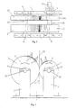
- the device which is shown in Figure 1 comprises a frame 1, in which a knife roller 2 and a pressure roller 3 are rotatably supported by means of bearings 4 and 5, respectively.
- the two rollers can rotate in opposite directions at the same peripheral velocity, as is indicated by arrows 6.
- Knife roller 2 is circumferentially provided with knives 7, which extend in axial direction with respect to roller 2.
- knives 7 are flexible pressure ribs 8, which likewise extend in axial direction along the circumferential surface.
- Figure 1 shows only a few of the knives 7 and pressure ribs 8.
- the pressure roller 3 is circumferentially provided with grooves 9, which extend in axial direction with respect to roller 3.
- Figure 1 also shows only a few of the grooves 9.
- Figure 1 shows a fibre 10 which is passed between rollers 2, 3 from above. Fibre 10 is clamped down in the pinch of rollers 2, 3 between pressure ribs 8 and the circumferential surface of pressure roller 3, and is pressed into grooves 9 by knives 7, whereby fibre 10 will break, or be cut through, so that pieces of fibre 11 will exit the pinch (indicated by a dashed line).
- pressure roller 3 is made of a metal, as are knives 7, and pressure ribs 8 are made of a flexible plastic. Since the cutting edge of the knives 7 does not come into contact with the bottom of grooves 9, the amount of wear, in particular on pressure roller 3, is extremely small. A proper cutting action is nevertheless obtained, due to the fact that the fibre 10 is firmly clamped down during cutting.
- Figure 2 is a top plan view of the device of Figure 1.
- Mounted on shaft 12 of knife roller 2 is a gear 13, which gear meshes with gear 14 mounted on shaft 15 of pressure roller 3.
- Gears 13, 14 have the same diameter as the respective roller 2, 3, so that rollers 2, 3 will rotate at the same peripheral velocity.
- Shafts 12, 15 are supported in frame 1 by means of bearings 4, 5, and shaft 15 of pressure roller 3 is connected to a driving shaft 16 for driving rollers 2, 3.
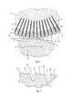
- Figures 3 - 6 all schematically illustrate the pinch between rollers 2, 3, showing the knife roller 2 positioned above pressure roller 3. Arrows 6 indicate the direction of rotation.
- Figure 3 shows the simplest embodiment.
- the figure shows that fibre 10 is engaged, on the left-hand side of the pinch, by the pressure rib 8 after said fibre has already been pressed slightly into groove 9 by knife 7. After clamping down the fibre, the knife will move further into the groove, cutting through the fibre. On the right-hand side of the pinch, the pieces of fibre 11 thus formed exit the pinch.
- Figure 4 shows a pressure roller 3, wherein the circumferential surface between the grooves does not extend cylindrically, but obliquely, that is, it includes an angle with the tangential direction. These portions of the circumferential surface are indicated at 17. Because of this arrangement, the ends of successive pieces of fibre 11 will not come into contact with each other as long as the pieces of fibre 11 are clamped down. This prevents said ends from getting damaged. Moreover, the pieces of fibre 11 will fall separately from the pinch.
- Figure 5 shows an embodiment wherein the pressure rib 8 is provided with a recess 18, which enables the knife to move further into the groove, because the pressure ribs 8 can be compressed further without this leading to a strongly increased pressure force.
- Figure 6 shows an embodiment wherein the circumferential surface 17 of the pressure roller 3 between grooves 9 not only extends obliquely, as is the case in Figure 4, but in addition is concave. This is conducive towards a proper engagement of fibre 10, since pressure roller 8 remains stably positioned in the deepest portion of the concave shape.
- Figure 7 is a more detailed view of the shape of pressure roller 3 of Figure 6, wherein the oblique position of groove 9 is clearly shown, which appears to function well in practice.
- Figure 7 furthermore shows that the edge 32, which forms the transition between groove 9 and surface 17, has a relatively large radius, so that fibre 10, which is stretched over said edge 32 during cutting, will not be damaged and will not break.
- Knife roller 2 is to that end provided with mounting sections 19, which extend in axial direction between knives 7.
- the pressure ribs 8 are placed onto mounting sections 19, which is possible because they are made of a flexible material.
- the pressure ribs 8 are slightly compressed in lateral direction, as a result of which they cannot become detached from mounting sections 19.
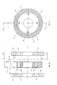
- Figure 8 shows a number of embodiments of the pressure rib 8 in elevation, which pressure ribs 8 are mounted on a mounting section 19. Said pressure ribs are provided with recess 18 (embodiments B, C and D) and/or cavities 20 (embodiments A and C), which makes them more easily compressible. Recesses 18 or cavities 20 may be filled with a flexible and/or compressible material, such as a foam material.
- Figure 8 (E) is a side elevation of the mounting section 19 with pressure rib 7 of Figure 8 (D).
- Figure 9 shows a knife roller 2 in longitudinal sectional view.
- the knife roller 2 is mounted on a shaft 12, which shaft comprises a portion 21 having a larger diameter present within knife roller 2, on which portion 21 the knife roller 2 is mounted by means of a key 22.
- the parts of knife roller 2 that are mounted on shaft 12 are shown in exploded view in Figure 10. They include two end flanges 23, 24 with a knife disc 25 positioned therebetween.
- said knife disc 25 is shown in elevation according to line XI - XI in Figure 10.
- Figure 11 shows the slots 26 into which the knives 7 can be moved, and the mounting sections 19 positioned therebetween.
- Figure 11 furthermore shows a knife 7, which knife 7 is shown in side elevation.
- Line X - X in Figure 11 indicates the section along which knife disc 25 is shown in Figure 10. It will be apparent that the knives 7 can be moved into slots 26 after the pressure ribs 8 have been placed onto the mounting sections 19. Then the knife disc 25 is mounted on portion 21 of shaft 12, after which the two end flanges 23, 24 are mounted in position by means of bolts (not shown), which extend through holes 27 and which are screwed into threaded holes 28. Knives 7 are retained by the ends 29 of knives 7, which extend into recesses 20 of the end flanges.
- a method for cutting fibres into pieces wherein a fibre (10) is divided into pieces by pressing a knife (7) against the fibre (10) without exerting a substantial counterpressure on the other side of the fibre (10) where the knife (7) is present.
- the fibre (10) is led between a knife roller (2), which is fitted with several, substantially axially oriented knives (7), and a pressure roller (3), which rollers (2, 3) are driven in opposite directions at the same peripheral velocity, wherein the fibre (10) is clamped down between pressure ribs (8), which are present between the knives (7) on the knife roller (2), and the pressure roller (3), wherein a knife (7) cuts through the fibre (10) substantially without counterpressure from the pressure roller (3).
- the knife (7) extends into a groove in the pressure roller (3) during cutting, to a depth some distance from the bottom of said groove (9).
- Said pressure rib (8) deforms more than the pressure roller (3) at the location where said clamping down takes place.
- the material of which the pressure ribs (8) are made is more flexible than the material of which the surface (17) of the pressure roller (3) is made.
- a cavity (20) or recess (18) is present in the material of the pressure rib (8).
- Said pressure rib (8) tapers off, seen in cross-sectional view, at least near the part which extends radially outwards.
- Said pressure rib (8) includes a substantially flat tangentially oriented part, which adjoins two sloping lateral surfaces, which extend as far as the knives (7).
- the radially outwardly extending part of the pressure rib (8) is positioned closer to the cutting edge of the preceding knife (7) than to the cutting edge of the next knife (7), seen in the direction of movement.
- the knives (7) are fixedly mounted on the knife roller (2), and the pressure ribs (8) between the knives (7) extend substantially as far in radially outward direction as the knives (7), and in that the pressure ribs (8) are pressed between the cutting knife (7) and the knives (7) adjacent thereto during cutting, to a position wherein they extend less far in radially outward direction than the cutting knife (7), the difference preferably being 0.3 mm or more, more preferably 0.7 mm or more, and even more preferably 1.2 or more.
- the knife roller (2) is provided with a substantially axially extending mounting section, and in that the pressure rib (8) is provided on the radially inward side with a recess corresponding to the mounting section (19), which engages round said mounting section (19).
- Said mounting section (19) is a strip mounted on the knife roller (2), which strip comprises a widened portion at its radial outer edge, around which the pressure rib (8) engages.
- the pressure rib (8) is made of a flexible material, the width of which material is greater than that of the space between the knives (7), so that the pressure rib (8) is clampingly engaged between the knives (7) under deformation.
- the surface of the pressure roller (3) is made of a metal or other hard material.
- the pressure rib (8) presses the fibre (10) against the pressure roller (3) at a location where the surface (17) of the pressure roller (3) is concave, seen in cross-sectional view.
- the pressure rib (8) presses the fibre (10) against the pressure roller (3) at a location where the surface (17) of the pressure roller (3) extends substantially obliquely with respect to the tangential plane.
- Said obliqueness is such that the forwardly extending part of said surface, seen in the direction of movement, is positioned closer to the axis of rotation of the pressure roller (3) than the rearwardly extending part.
- the circumferential surface of the pressure roller (3) is provided with substantially axially extending grooves, wherein the edge (32) between the side wall of the groove (9) and the adjoining part (17) of the circumferential surface of the pressure roller (3) is rounded, the radius thereof being larger than that of the cutting edge of the knife (7), said radius preferably being larger than 0.1 mm, more preferably larger than 0.2 mm.
- the circumferential surface of the pressure roller (3) is provided with substantially axially oriented grooves (9), into which the knives (7) can extend during cutting.
- the material of which the pressure ribs (8) are made is more flexible than the material of which the surface of the pressure roller (3) is made.
- a cavity (20) or recess (18) is present in the material of said pressure rib.
- Said pressure rib (8) tapers off, seen in cross-sectional view, at least near the part which extends radially outwards.
- Said pressure rib (8) includes a substantially flat tangentially oriented part, which adjoins two sloping lateral surfaces, which extend as far as the knives (7).
- the radially outwardly extending part of the pressure rib (8) is positioned closer to the cutting edge of the preceding knife (7) than to the cutting edge of the next knife (7), seen in the direction of movement.
- the knives (7) are fixedly mounted on the knife roller (2), and the pressure ribs (8) between the knives (7) can extend substantially as far in radially outward direction as the knives (7), and in that the pressure ribs (8) are pressed between the cutting knife (7) and the knives (7) adjacent thereto during cutting, to a position wherein they extend less far in radially outward direction than the cutting knife (7), the difference preferably being 0.5 mm or more, more preferably 1 mm or more.
- the knife roller (2) is provided with a substantially axially extending mounting section, and in that the pressure rib (8) is provided on the radially inward side with a recess corresponding to the mounting section (19), which engages round said mounting section (19).
- the mounting section (19) is a strip mounted on the knife roller (2), which strip comprises a widened portion at its radial outer edge, around which the pressure rib (8) engages.
- the pressure rib (8) is made of a flexible material, the width of which material is greater than that of the space between the knives (7), so that the pressure rib (8) is clampingly engaged between the knives (7) under deformation.
- the surface of the pressure roller (3) is made of a metal or other hard material.
- the pressure rib (8) presses the fibre (10) against the pressure roller (3) at a location where the surface (17) of the pressure roller (3) is concave, seen in cross-sectional view.
- the pressure rib (8) presses the fibre (10) against the pressure roller (3) at a location where the surface (17) of the pressure roller (3) extends substantially obliquely with respect to the tangential plane.
- Said obliqueness is such that the forwardly extending part of said surface, seen in the direction of movement, is positioned closer to the axis of rotation of the pressure roller (3) than the rearwardly extending part.
- the circumferential surface of the pressure roller (3) is provided with substantially axially extending grooves, wherein the edge (32) between the side wall of the groove (9) and the adjoining part (17) of the circumferential surface of the pressure roller (3) is rounded, the radius thereof being larger than that of the cutting edge of the knife (7), said radius preferably being larger than 0.1 mm, more preferably larger than 0.2 mm.
Landscapes
- Engineering & Computer Science (AREA)
- Textile Engineering (AREA)
- Preliminary Treatment Of Fibers (AREA)
Abstract
Description
Claims (10)
- A device for cutting fibres into pieces, wherein a fibre (10) is divided into pieces (11) by pressing a knife (7) against the fibre (10), said device including a knife roller (2) comprising several substantially axially oriented knives (7) and pressure ribs (8) which are present between the knives (7), and a pressure roller (3), which rollers (2, 3) can be driven in opposite directions at the same peripheral velocity, characterized in that the knife roller (2) is provided with substantially axially extending mounting sections (19), and in that the pressure ribs (8) are provided on the radially inward side with a recess corresponding to the mounting section (19), which engages round said mounting section (19).
- A device according to claim 1, characterized in that the material of which the pressure ribs (8) are made is more flexible than the material of which the surface of the pressure roller (3) is made.
- A device according to claims 1 or 2, characterized in that a cavity (20) or recess (18) is present in the material of said pressure rib (8).
- A device according to any one of the claims 1 - 3, characterized in that said pressure rib (8) tapers off, seen in cross-sectional view, at least near the part which extends radially outwards.
- A device according to claim 4, characterized in that said pressure rib (8) includes a substantially flat tangentially oriented part, which adjoins two sloping lateral surfaces, which extend as far as the knives (7).
- A device according to any one of the claims 1 - 5, characterized in that the radially outwardly extending part of the pressure rib (8) is positioned closer to the cutting edge of the preceding knife (7) than to the cutting edge of the next knife (7), seen in the direction of movement.
- A device according to any one of the claims 1 - 6, characterized in that the knives (7) are fixedly mounted on the knife roller (2), and the pressure ribs (8) between the knives (7) can extend substantially as far in radially outward direction as the knives (7), and in that the pressure ribs (8) are pressed between the cutting knife (7) and the knives (7) adjacent thereto during cutting, to a position wherein they extend less far in radially outward direction than the cutting knife (7), the difference preferably being 0.5 mm or more, more preferably 1 mm or more.
- A device according to any one of the claims 1 - 7, characterized in that said mounting section (19) is a strip mounted on the knife roller (2), which strip comprises a widened portion at its radial outer edge, around which the pressure rib (8) engages.
- A device according to any one of the claims 1 - 8, characterized in that the pressure rib (8) is made of a flexible material, the width of which material is greater than that of the space between the knives (7), so that the pressure rib (8) is clampingly engaged between the knives (7) under deformation.
- Pressure rib (8) for mounting on a substantially axially extending mounting sections (19) between substantially axially oriented knives (7) of a knife roller (2) of a device for cutting fibres into pieces, wherein a fibre (10) is divided into pieces (11) by pressing the knives (7) against the fibre (10), said device further comprising a pressure roller (3), which rollers (2, 3) can be driven in opposite directions at the same peripheral velocity, wherein the pressure rib (8) is provided on the radially inward side with a recess corresponding to the mounting section (19), which engages round said mounting section (19).
Applications Claiming Priority (5)
| Application Number | Priority Date | Filing Date | Title |
|---|---|---|---|
| NL1010665 | 1998-11-27 | ||
| NL1010665A NL1010665C2 (en) | 1998-11-27 | 1998-11-27 | Cutting of fibers e.g. glass fibers involves pressing knife against fiber without exerting counterpressure on other side of fiber where knife is present |
| NL1012286 | 1999-06-10 | ||
| NL1012286A NL1012286C2 (en) | 1998-11-27 | 1999-06-10 | Method and device for cutting fibers. |
| EP99973082A EP1144738B1 (en) | 1998-11-27 | 1999-11-22 | Method and device for cutting fibres into pieces |
Related Parent Applications (1)
| Application Number | Title | Priority Date | Filing Date |
|---|---|---|---|
| EP99973082A Division EP1144738B1 (en) | 1998-11-27 | 1999-11-22 | Method and device for cutting fibres into pieces |
Publications (3)
| Publication Number | Publication Date |
|---|---|
| EP1394295A2 true EP1394295A2 (en) | 2004-03-03 |
| EP1394295A3 EP1394295A3 (en) | 2004-03-17 |
| EP1394295B1 EP1394295B1 (en) | 2006-04-05 |
Family
ID=26642882
Family Applications (2)
| Application Number | Title | Priority Date | Filing Date |
|---|---|---|---|
| EP99973082A Expired - Lifetime EP1144738B1 (en) | 1998-11-27 | 1999-11-22 | Method and device for cutting fibres into pieces |
| EP03078077A Expired - Lifetime EP1394295B1 (en) | 1998-11-27 | 1999-11-22 | Device and pressure rib for cutting fibres into pieces |
Family Applications Before (1)
| Application Number | Title | Priority Date | Filing Date |
|---|---|---|---|
| EP99973082A Expired - Lifetime EP1144738B1 (en) | 1998-11-27 | 1999-11-22 | Method and device for cutting fibres into pieces |
Country Status (6)
| Country | Link |
|---|---|
| EP (2) | EP1144738B1 (en) |
| AT (2) | ATE322564T1 (en) |
| DE (2) | DE69930772T2 (en) |
| ES (2) | ES2214069T3 (en) |
| NL (1) | NL1012286C2 (en) |
| WO (1) | WO2000032856A1 (en) |
Cited By (2)
| Publication number | Priority date | Publication date | Assignee | Title |
|---|---|---|---|---|
| EP2727694A1 (en) | 2012-11-05 | 2014-05-07 | Toho Tenax Europe GmbH | Lowering device for controlled lowering of reinforcement fibre bundles |
| EP2727693A1 (en) | 2012-11-05 | 2014-05-07 | Toho Tenax Europe GmbH | Method for manufacturing fibre preforms |
Families Citing this family (7)
| Publication number | Priority date | Publication date | Assignee | Title |
|---|---|---|---|---|
| NL1017098C2 (en) * | 2001-01-12 | 2002-07-15 | Willem Frans Van Der Mast | Method and device for cutting fibers. |
| FR2904331B1 (en) * | 2006-07-26 | 2008-09-26 | Saint Gobain Vetrotex | PERFECTED CUTTING WHEEL |
| CN104153045A (en) * | 2014-07-31 | 2014-11-19 | 扬中市金德纺织机械设备厂 | Double-cutter cotton-escape preventing fiber cutting machine |
| CN107151836A (en) * | 2017-07-12 | 2017-09-12 | 苏州多凯复合材料有限公司 | The material cutting mechanism of FRP plate fiber stock-cutter |
| CN113493945B (en) * | 2021-08-24 | 2022-12-23 | 晋江市众拓服装织造有限公司 | A kind of textile ramie fiber cutting method |
| CN116175850B (en) * | 2023-04-06 | 2025-12-09 | 浙江绿环新材料科技有限公司 | Powder coating production equipment and process thereof |
| CN118241342B (en) * | 2024-05-28 | 2024-08-06 | 江苏友诚数控科技有限公司 | Processing apparatus is cut to weaving silk fibre |
Family Cites Families (8)
| Publication number | Priority date | Publication date | Assignee | Title |
|---|---|---|---|---|
| DE969611C (en) * | 1951-06-27 | 1958-06-26 | Ernst Reiffen Dipl Ing | Device for cutting tow or other ribbon or strand-shaped material |
| US3353431A (en) * | 1965-02-23 | 1967-11-21 | Monsanto Co | Stable fiber cutter |
| US3508461A (en) * | 1967-10-04 | 1970-04-28 | Owens Corning Fiberglass Corp | Chopper for glass strands |
| DE1933374A1 (en) * | 1969-07-01 | 1971-01-07 | Du Pont | Conversion of tow to staple fibre |
| FR2322836A1 (en) * | 1975-09-04 | 1977-04-01 | Saint Gobain | METHOD AND DEVICES FOR CUTTING MINERAL THREADS, IN PARTICULAR GLASS YARNS |
| US4083279A (en) * | 1976-05-10 | 1978-04-11 | Johns-Manville Corporation | Apparatus for chopping strand |
| JPH0791699B2 (en) * | 1987-12-28 | 1995-10-04 | 帝人株式会社 | Fiber cutting equipment |
| JPH0688235B2 (en) * | 1989-07-31 | 1994-11-09 | 日東紡績株式会社 | Fiber bundle cutting device |
-
1999
- 1999-06-10 NL NL1012286A patent/NL1012286C2/en not_active IP Right Cessation
- 1999-11-22 ES ES99973082T patent/ES2214069T3/en not_active Expired - Lifetime
- 1999-11-22 DE DE69930772T patent/DE69930772T2/en not_active Expired - Lifetime
- 1999-11-22 AT AT03078077T patent/ATE322564T1/en active
- 1999-11-22 ES ES03078077T patent/ES2257641T3/en not_active Expired - Lifetime
- 1999-11-22 AT AT99973082T patent/ATE259896T1/en active
- 1999-11-22 WO PCT/NL1999/000715 patent/WO2000032856A1/en not_active Ceased
- 1999-11-22 EP EP99973082A patent/EP1144738B1/en not_active Expired - Lifetime
- 1999-11-22 DE DE69914949T patent/DE69914949T2/en not_active Expired - Lifetime
- 1999-11-22 EP EP03078077A patent/EP1394295B1/en not_active Expired - Lifetime
Cited By (6)
| Publication number | Priority date | Publication date | Assignee | Title |
|---|---|---|---|---|
| EP2727694A1 (en) | 2012-11-05 | 2014-05-07 | Toho Tenax Europe GmbH | Lowering device for controlled lowering of reinforcement fibre bundles |
| EP2727693A1 (en) | 2012-11-05 | 2014-05-07 | Toho Tenax Europe GmbH | Method for manufacturing fibre preforms |
| WO2014067762A1 (en) | 2012-11-05 | 2014-05-08 | Toho Tenax Europe Gmbh | Depositing device for the controlled deposition of reinforcing fibre bundles |
| WO2014067763A1 (en) | 2012-11-05 | 2014-05-08 | Toho Tenax Europe Gmbh | Method for producing fibre preforms |
| US10052654B2 (en) | 2012-11-05 | 2018-08-21 | Teijin Carbon Europe Gmbh | Deposition device for controlled deposition of reinforcing fiber bundles |
| US10059042B2 (en) | 2012-11-05 | 2018-08-28 | Teijin Carbon Europe Gmbh | Method for producing fiber preforms |
Also Published As
| Publication number | Publication date |
|---|---|
| NL1012286C2 (en) | 2000-05-30 |
| ATE322564T1 (en) | 2006-04-15 |
| DE69914949D1 (en) | 2004-03-25 |
| DE69914949T2 (en) | 2004-12-09 |
| EP1144738A1 (en) | 2001-10-17 |
| DE69930772D1 (en) | 2006-05-18 |
| EP1394295A3 (en) | 2004-03-17 |
| ES2257641T3 (en) | 2006-08-01 |
| ATE259896T1 (en) | 2004-03-15 |
| EP1144738B1 (en) | 2004-02-18 |
| ES2214069T3 (en) | 2004-09-01 |
| EP1394295B1 (en) | 2006-04-05 |
| DE69930772T2 (en) | 2006-11-16 |
| WO2000032856A1 (en) | 2000-06-08 |
Similar Documents
| Publication | Publication Date | Title |
|---|---|---|
| EP1394295B1 (en) | Device and pressure rib for cutting fibres into pieces | |
| US5887702A (en) | Trailing arm secondary belt cleaner | |
| KR101418142B1 (en) | Punching scrap removal device and blade mount for rotary die cutter | |
| GB2140376A (en) | Carrier for a drag chain conveyor for loose articles | |
| US7021457B1 (en) | Conveyor belt drive roller | |
| US4233853A (en) | Belt pulley | |
| US5092207A (en) | Fiber bundle cutting device | |
| NO318086B1 (en) | Peeler with segmented roller assemblies | |
| US4796680A (en) | Apparatus for tenderizing veneer sheets | |
| US5281189A (en) | Crowned pulley for a belt conveyor | |
| EP1342842A3 (en) | Doctor blade for removing water | |
| DE19756711C2 (en) | Support disc bearing for an open-end spinning rotor | |
| US3890706A (en) | Roving cutter for fiber reinforced synthetic resin sprayers | |
| WO2002055770A1 (en) | Method and device for cutting fibres | |
| US3965765A (en) | Pulley | |
| US6336852B1 (en) | Roll with surface coating | |
| DE69809068T2 (en) | DRIVE WHEEL | |
| US4174551A (en) | Feather plucking device | |
| US3028906A (en) | Apparatus for straightening discs | |
| EP1388680A3 (en) | Pressure plate for a friction clutch | |
| SU802088A1 (en) | Device for removing outer rubber layer from high-pressure hoses | |
| EP0906809A1 (en) | Improved centrifugal expansion roller for sanding machines | |
| JP3014798U (en) | Pressure contact roll for fiber cutting device and fiber cutting device using the same | |
| KR200301279Y1 (en) | A side trimmer having a knife to mouted the same ealily | |
| DE29505461U1 (en) | Rubber conveyor roller |
Legal Events
| Date | Code | Title | Description |
|---|---|---|---|
| PUAI | Public reference made under article 153(3) epc to a published international application that has entered the european phase |
Free format text: ORIGINAL CODE: 0009012 |
|
| PUAL | Search report despatched |
Free format text: ORIGINAL CODE: 0009013 |
|
| AC | Divisional application: reference to earlier application |
Ref document number: 1144738 Country of ref document: EP Kind code of ref document: P |
|
| AK | Designated contracting states |
Kind code of ref document: A2 Designated state(s): AT BE CH CY DE DK ES FI FR GB GR IE IT LI LU MC NL PT SE |
|
| AK | Designated contracting states |
Kind code of ref document: A3 Designated state(s): AT BE CH CY DE DK ES FI FR GB GR IE IT LI LU MC NL PT SE |
|
| 17P | Request for examination filed |
Effective date: 20040915 |
|
| AKX | Designation fees paid |
Designated state(s): AT BE CH CY DE DK ES FI FR GB GR IE IT LI LU MC NL PT SE |
|
| GRAP | Despatch of communication of intention to grant a patent |
Free format text: ORIGINAL CODE: EPIDOSNIGR1 |
|
| GRAS | Grant fee paid |
Free format text: ORIGINAL CODE: EPIDOSNIGR3 |
|
| GRAA | (expected) grant |
Free format text: ORIGINAL CODE: 0009210 |
|
| AC | Divisional application: reference to earlier application |
Ref document number: 1144738 Country of ref document: EP Kind code of ref document: P |
|
| AK | Designated contracting states |
Kind code of ref document: B1 Designated state(s): AT BE CH CY DE DK ES FI FR GB GR IE IT LI LU MC NL PT SE |
|
| PG25 | Lapsed in a contracting state [announced via postgrant information from national office to epo] |
Ref country code: IT Free format text: LAPSE BECAUSE OF FAILURE TO SUBMIT A TRANSLATION OF THE DESCRIPTION OR TO PAY THE FEE WITHIN THE PRESCRIBED TIME-LIMIT;WARNING: LAPSES OF ITALIAN PATENTS WITH EFFECTIVE DATE BEFORE 2007 MAY HAVE OCCURRED AT ANY TIME BEFORE 2007. THE CORRECT EFFECTIVE DATE MAY BE DIFFERENT FROM THE ONE RECORDED. Effective date: 20060405 Ref country code: LI Free format text: LAPSE BECAUSE OF FAILURE TO SUBMIT A TRANSLATION OF THE DESCRIPTION OR TO PAY THE FEE WITHIN THE PRESCRIBED TIME-LIMIT Effective date: 20060405 Ref country code: CH Free format text: LAPSE BECAUSE OF FAILURE TO SUBMIT A TRANSLATION OF THE DESCRIPTION OR TO PAY THE FEE WITHIN THE PRESCRIBED TIME-LIMIT Effective date: 20060405 |
|
| REG | Reference to a national code |
Ref country code: GB Ref legal event code: FG4D |
|
| REG | Reference to a national code |
Ref country code: CH Ref legal event code: EP |
|
| REG | Reference to a national code |
Ref country code: IE Ref legal event code: FG4D |
|
| REF | Corresponds to: |
Ref document number: 69930772 Country of ref document: DE Date of ref document: 20060518 Kind code of ref document: P |
|
| PG25 | Lapsed in a contracting state [announced via postgrant information from national office to epo] |
Ref country code: DK Free format text: LAPSE BECAUSE OF FAILURE TO SUBMIT A TRANSLATION OF THE DESCRIPTION OR TO PAY THE FEE WITHIN THE PRESCRIBED TIME-LIMIT Effective date: 20060705 Ref country code: SE Free format text: LAPSE BECAUSE OF FAILURE TO SUBMIT A TRANSLATION OF THE DESCRIPTION OR TO PAY THE FEE WITHIN THE PRESCRIBED TIME-LIMIT Effective date: 20060705 |
|
| REG | Reference to a national code |
Ref country code: ES Ref legal event code: FG2A Ref document number: 2257641 Country of ref document: ES Kind code of ref document: T3 |
|
| PG25 | Lapsed in a contracting state [announced via postgrant information from national office to epo] |
Ref country code: PT Free format text: LAPSE BECAUSE OF FAILURE TO SUBMIT A TRANSLATION OF THE DESCRIPTION OR TO PAY THE FEE WITHIN THE PRESCRIBED TIME-LIMIT Effective date: 20060905 |
|
| ET | Fr: translation filed | ||
| REG | Reference to a national code |
Ref country code: CH Ref legal event code: PL |
|
| PG25 | Lapsed in a contracting state [announced via postgrant information from national office to epo] |
Ref country code: IE Free format text: LAPSE BECAUSE OF NON-PAYMENT OF DUE FEES Effective date: 20061122 |
|
| PG25 | Lapsed in a contracting state [announced via postgrant information from national office to epo] |
Ref country code: MC Free format text: LAPSE BECAUSE OF NON-PAYMENT OF DUE FEES Effective date: 20061130 |
|
| PLBE | No opposition filed within time limit |
Free format text: ORIGINAL CODE: 0009261 |
|
| STAA | Information on the status of an ep patent application or granted ep patent |
Free format text: STATUS: NO OPPOSITION FILED WITHIN TIME LIMIT |
|
| 26N | No opposition filed |
Effective date: 20070108 |
|
| PG25 | Lapsed in a contracting state [announced via postgrant information from national office to epo] |
Ref country code: GR Free format text: LAPSE BECAUSE OF FAILURE TO SUBMIT A TRANSLATION OF THE DESCRIPTION OR TO PAY THE FEE WITHIN THE PRESCRIBED TIME-LIMIT Effective date: 20060706 |
|
| PG25 | Lapsed in a contracting state [announced via postgrant information from national office to epo] |
Ref country code: LU Free format text: LAPSE BECAUSE OF NON-PAYMENT OF DUE FEES Effective date: 20061122 |
|
| PG25 | Lapsed in a contracting state [announced via postgrant information from national office to epo] |
Ref country code: CY Free format text: LAPSE BECAUSE OF FAILURE TO SUBMIT A TRANSLATION OF THE DESCRIPTION OR TO PAY THE FEE WITHIN THE PRESCRIBED TIME-LIMIT Effective date: 20060405 |
|
| PGFP | Annual fee paid to national office [announced via postgrant information from national office to epo] |
Ref country code: FI Payment date: 20111124 Year of fee payment: 13 Ref country code: ES Payment date: 20111130 Year of fee payment: 13 |
|
| PGFP | Annual fee paid to national office [announced via postgrant information from national office to epo] |
Ref country code: BE Payment date: 20121128 Year of fee payment: 14 Ref country code: IT Payment date: 20121129 Year of fee payment: 14 |
|
| PGFP | Annual fee paid to national office [announced via postgrant information from national office to epo] |
Ref country code: NL Payment date: 20121130 Year of fee payment: 14 |
|
| PG25 | Lapsed in a contracting state [announced via postgrant information from national office to epo] |
Ref country code: FI Free format text: LAPSE BECAUSE OF NON-PAYMENT OF DUE FEES Effective date: 20121122 |
|
| REG | Reference to a national code |
Ref country code: ES Ref legal event code: FD2A Effective date: 20140306 |
|
| PG25 | Lapsed in a contracting state [announced via postgrant information from national office to epo] |
Ref country code: ES Free format text: LAPSE BECAUSE OF NON-PAYMENT OF DUE FEES Effective date: 20121123 |
|
| BERE | Be: lapsed |
Owner name: *VAN DER MAST WILLEM FRANS Effective date: 20131130 |
|
| REG | Reference to a national code |
Ref country code: NL Ref legal event code: V1 Effective date: 20140601 |
|
| PG25 | Lapsed in a contracting state [announced via postgrant information from national office to epo] |
Ref country code: NL Free format text: LAPSE BECAUSE OF NON-PAYMENT OF DUE FEES Effective date: 20140601 Ref country code: IT Free format text: LAPSE BECAUSE OF NON-PAYMENT OF DUE FEES Effective date: 20131122 |
|
| PG25 | Lapsed in a contracting state [announced via postgrant information from national office to epo] |
Ref country code: BE Free format text: LAPSE BECAUSE OF NON-PAYMENT OF DUE FEES Effective date: 20131130 |
|
| REG | Reference to a national code |
Ref country code: FR Ref legal event code: PLFP Year of fee payment: 17 |
|
| REG | Reference to a national code |
Ref country code: FR Ref legal event code: PLFP Year of fee payment: 18 |
|
| REG | Reference to a national code |
Ref country code: FR Ref legal event code: PLFP Year of fee payment: 19 |
|
| PGFP | Annual fee paid to national office [announced via postgrant information from national office to epo] |
Ref country code: FR Payment date: 20171127 Year of fee payment: 19 Ref country code: DE Payment date: 20171129 Year of fee payment: 19 |
|
| PGFP | Annual fee paid to national office [announced via postgrant information from national office to epo] |
Ref country code: GB Payment date: 20171127 Year of fee payment: 19 |
|
| PGFP | Annual fee paid to national office [announced via postgrant information from national office to epo] |
Ref country code: AT Payment date: 20161130 Year of fee payment: 18 |
|
| REG | Reference to a national code |
Ref country code: AT Ref legal event code: MM01 Ref document number: 322564 Country of ref document: AT Kind code of ref document: T Effective date: 20171122 |
|
| PG25 | Lapsed in a contracting state [announced via postgrant information from national office to epo] |
Ref country code: AT Free format text: LAPSE BECAUSE OF NON-PAYMENT OF DUE FEES Effective date: 20171122 |
|
| REG | Reference to a national code |
Ref country code: DE Ref legal event code: R119 Ref document number: 69930772 Country of ref document: DE |
|
| GBPC | Gb: european patent ceased through non-payment of renewal fee |
Effective date: 20181122 |
|
| PG25 | Lapsed in a contracting state [announced via postgrant information from national office to epo] |
Ref country code: DE Free format text: LAPSE BECAUSE OF NON-PAYMENT OF DUE FEES Effective date: 20190601 Ref country code: FR Free format text: LAPSE BECAUSE OF NON-PAYMENT OF DUE FEES Effective date: 20181130 |
|
| PG25 | Lapsed in a contracting state [announced via postgrant information from national office to epo] |
Ref country code: GB Free format text: LAPSE BECAUSE OF NON-PAYMENT OF DUE FEES Effective date: 20181122 |