EP1394007A1 - Betätigungsmittel zum Beeinflussen einer Anlage zum Bremsen, Kuppeln oder Antrieb eines Kraftfahrzeuges - Google Patents
Betätigungsmittel zum Beeinflussen einer Anlage zum Bremsen, Kuppeln oder Antrieb eines Kraftfahrzeuges Download PDFInfo
- Publication number
- EP1394007A1 EP1394007A1 EP03011688A EP03011688A EP1394007A1 EP 1394007 A1 EP1394007 A1 EP 1394007A1 EP 03011688 A EP03011688 A EP 03011688A EP 03011688 A EP03011688 A EP 03011688A EP 1394007 A1 EP1394007 A1 EP 1394007A1
- Authority
- EP
- European Patent Office
- Prior art keywords
- actuating means
- driver
- brake
- pedal
- means according
- Prior art date
- Legal status (The legal status is an assumption and is not a legal conclusion. Google has not performed a legal analysis and makes no representation as to the accuracy of the status listed.)
- Granted
Links
Images


Classifications
-
- G—PHYSICS
- G05—CONTROLLING; REGULATING
- G05G—CONTROL DEVICES OR SYSTEMS INSOFAR AS CHARACTERISED BY MECHANICAL FEATURES ONLY
- G05G1/00—Controlling members, e.g. knobs or handles; Assemblies or arrangements thereof; Indicating position of controlling members
- G05G1/30—Controlling members actuated by foot
- G05G1/42—Controlling members actuated by foot non-pivoting, e.g. sliding
-
- B—PERFORMING OPERATIONS; TRANSPORTING
- B60—VEHICLES IN GENERAL
- B60T—VEHICLE BRAKE CONTROL SYSTEMS OR PARTS THEREOF; BRAKE CONTROL SYSTEMS OR PARTS THEREOF, IN GENERAL; ARRANGEMENT OF BRAKING ELEMENTS ON VEHICLES IN GENERAL; PORTABLE DEVICES FOR PREVENTING UNWANTED MOVEMENT OF VEHICLES; VEHICLE MODIFICATIONS TO FACILITATE COOLING OF BRAKES
- B60T7/00—Brake-action initiating means
- B60T7/02—Brake-action initiating means for personal initiation
- B60T7/04—Brake-action initiating means for personal initiation foot actuated
- B60T7/042—Brake-action initiating means for personal initiation foot actuated by electrical means, e.g. using travel or force sensors
-
- G—PHYSICS
- G05—CONTROLLING; REGULATING
- G05G—CONTROL DEVICES OR SYSTEMS INSOFAR AS CHARACTERISED BY MECHANICAL FEATURES ONLY
- G05G1/00—Controlling members, e.g. knobs or handles; Assemblies or arrangements thereof; Indicating position of controlling members
- G05G1/30—Controlling members actuated by foot
Definitions
- the invention relates to an actuating means for influencing a system for braking, coupling or driving a motor vehicle, which of a driver actuated actuating means mechanically by the actuators System is decoupled.
- the known actuating means of a drive, brake or clutch system of a motor vehicle consists of a foot pedal (accelerator, brake and / or clutch pedal).
- the operating principle of the foot pedal consists of walking through a swivel path as a result of manual pressure.
- a pedal in the form of a pedal lever is considered, which generates a signal and forwards it to control a drive, brake or clutch system.
- this can be, for example, an electro-hydraulic brake system (at least with a control unit, hydraulic unit and brake means for the wheel) or an electromechanical brake system.
- An essential aspect of such a known pedal as an actuating means is that it is mechanically decoupled from the rest of the system. Nevertheless, a pedal travel is provided in the actuating means in the prior art in order to convey the known pedal feeling to the driver.
- actuating means to control drive or deceleration means in the motor vehicle. It’s the job of developing a foot operated actuator, which due to its constructive design in the event of a frontal impact of the motor vehicle foot injuries significantly reduced.
- the purpose of the actuating means consists of a pressure transducer Housing part, which is compared to its mounting surface by means of foot movement is vertically displaceable in relation to a spring force Level of the mounting surface.
- the actuator is from the drive or Mechanically decoupled delay means. There are no injuries Construction elements of a conventional pedal device.
- the solution has the disadvantage that there is always a device for simulating a conventional pedal device is used. Consequently the impression is meant to be a conventional pedal operation for the driver are retained.
- the consideration of the pedal travel is complex and ergonomically unfavorable. To avoid confusion between the accelerator and brake pedals, For example, a step change was introduced between the two pedals.
- the necessary pedal bracket is an additional one when using the pedal Component that generates costs and reduces impact safety.
- the object of the invention is one of a drive, clutch or Brake system mechanically decoupled actuating means of a motor vehicle to simplify significantly to the disadvantages of the prior art to diminish. There should be no additional design effort arise.
- the actuating means can be used as a piezoceramic force transducer, as a strain gauge or be formed in combination.
- the force transducer can also be replaced by a snapshot when rotating Forces would have to be recorded.
- the actuating means can be in the footwell of the driver or in the area of the steering wheel. With electrohydraulic Braking systems that require a pedal should be the actuating means be arranged on the foot pedal.
- the actuating means could in general also be redundant.
- the actuating means can be in an Logic block of the system stored threshold value of the force set, if this is exceeded, only a signal for influencing the system generated.
- the invention can be used in motor vehicles where there is an actuating means without an actuation path influencing the system is.
- the invention preferably leaves the known path, for example when determining the driver brake request, the driver is used to it To convey the feeling of a pedal stroke.
- the Invention also in a (technically related) pedal-guided brake system possible.
- the invention intends to use an actuation means that is generally “pathless” for the driver, ie, actuation means that can be actuated without an actuation path.
- the invention does not require an actuation path on the actuating means and basically dispenses with the generation of a signal which is dependent on the actuation path and which corresponds to the corresponding system, e.g. B. brake system is to be supplied as a driver brake request.
- the actuation means detects the driver's individual actuation force, which is independent of an actuation path.
- the actuating means is a transducer that detects the force or a moment and converts it directly into an equivalent signal (control signal), preferably an electrical signal, regardless of an actuation path.
- the actuating means serves to influence (actuate) a drive system (Vehicle engine) or the braking system of the vehicle or the Clutch system of a vehicle.
- the actuating means is used to detect a Driver speed request, which is used in electrical control signals for subsequent Engine control units is converted, which is the basis for the Changing the speed of the vehicle engine, d. H. for the change form the vehicle speed.
- the actuating means is used to record a driver's braking request, in electrical control signals for brake control units is converted, which to initiate a deceleration of the vehicle is used by the brake system.
- the actuating means is used to detect a Driver clutch request, which converts into electrical control signals is and the clutch control is fed and there to initiate a Coupling process by means of clutch system is used.
- the corresponding Actuators of the engine, brake or clutch system form the actuators.
- the actuating means can be actuated by the driver by foot or by hand.
- the actuating means is arranged in the driver's known footwell.
- the Actuating means can for example be arranged in the area of the steering wheel his.
- an actuating means is illustrated using the example of an electromechanical brake.
- the exemplary embodiment considers an actuating means for the brake system described according to the invention, wherein the other two actuating means for the clutch system and vehicle drive can be designed in a conventional manner.
- Arranged in the footwell for the driver of a motor vehicle are, for example, a clutch pedal of a known type, an accelerator pedal of a known type and an actuating means according to the invention for the brake system.
- the well-known brake pedal in the footwell on the driver's side is eliminated.
- a sensor is arranged as an actuating means on the rigid floor of the footwell there, which basically does not simulate an actuation path and does not require an actuation path for foot operation by the driver. This requirement is met, for example, by using a strain gauge or a piezoceramic as an actuating means. Strain gauges or piezoceramic can be arranged between the clutch pedal and the accelerator pedal and can, for example, extend over an area up to the size of the footwear. A delimited, distinguishable area is intended for the purpose of position detection.
- the actuating means has no actuation path.
- the force transducer can accordingly redundant, i.e. in an emergency there is a switch to one second, parallel load cell or a permanent evaluation and plausibility check of existing signals.
- the change in foot strength can also be evaluated as an additional signal become.
- the change in foot strength can be determined from a corresponding sensor or generated in the control unit from the time profile of the foot power signal become.
- Control unit 30 includes at least one Logic block 4 for calculating the driver's brake request, which one calculated driver brake request signal 5 to a logic block 6 (with priority control) transmitted.
- a can be in the logic block 4 (400) Threshold value to be stored in the memory, which is an amount of force represents a control signal is only generated when exceeded to influence the brake system. This makes it possible for a lower, groping foot power to find or position the Driver's foot does not immediately trigger a driver brake request.
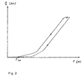
- the wheel brake pressure P R is shown as a function of the driver's foot force F. Below an empirically determined threshold value F SW of the foot force, this is accepted as a "pedal search force" which does not trigger a deceleration reaction of the vehicle.
- the wheel brake pressure P R consequently has the value zero, although a foot force F is present, for example when groping for the actuating means.
- the deceleration request is implemented as a function of the foot force by means of a corresponding wheel brake pressure.
- the characteristic curve increases relatively gently. This corresponds to a "soft" braking behavior and brings good controllability of the braking force of the braking means generated by the wheel brake pressure. This is useful when parking and exiting or gently braking to a standstill (stopping smoothly).
- the characteristic curve can be continued, for example, by a linear increase. If it is foreseeable that the driver's braking request will be fulfilled and the foot power will therefore decrease, the wheel brake pressure does not have to drop immediately.
- the drop in the wheel brake pressure P R takes place somewhat delayed and in a now offset, downward-running characteristic curve.
- the downward characteristic is similar to the upward characteristic, but with an existing hysteresis.
- the control of the wheel brakes is carried out by the control unit 30 via the signal path 7.
- the logic block 6 can receive additional input variables 9 (such as, for example, deceleration requests from other systems, interventions by wheel slip control systems).
- the control unit 30 supplies an actuating signal to control the individual wheel brake.
- the individual wheel brake is formed by an actuator which can be influenced electrically and acts on a known wheel brake.
- FIG. 2 shows the use of a force-absorbing actuating means 100 (also called force transducer hereinafter) in connection with a known electrohydraulic brake system 300.
- a force-absorbing actuating means 100 also called force transducer hereinafter
- the pedal 101 is rotatably supported as a lever in a known manner and is connected to the piston rod of a hydraulic pressure cylinder 304.
- the pressure cylinder 304 is connected to a pressure sensor 310, which generates an electrical signal proportional to the hydraulic pressure, which is fed to the control unit 301.
- the pressure cylinder 304 is separated from the hydraulic brake circuit by isolating valves 350 and can only be used as an emergency aid device in an emergency by closing the isolating valves 350.
- At least one transducer 100 is installed, which one Force transducer is.
- the force transducer 100 as an actuating means can alternatively also on the foot pedal surface or in the structure of the Foot pedal can be arranged.
- a force transducer 100 is, for example Strain gauges or a piezoceramic used.
- the on the Force transducer 100 foot force is applied directly into an electrical signal converted, which is transmitted to the control unit 301.
- the logic block 400 for calculating the driver brake request receives both the signal of the force transducer 100, as well as the signal of the hydraulic Printing cylinder 304.
- logic block 400 for calculating the Driver braking requests are stored in software programs, one for the Determine representative driver signal 360 and send it to one Communicate logic block 390 for priority control.
- the priorities in the control of the individual brake means on the wheel Logic block 390 for priority control can still have external input variables 380 (braking requirements, etc. of other systems, e.g. Wheel slip control system) be introduced.
- Control unit 301 switches on Signal 370 for target specification of the wheel brake pressure to the individual wheel pressure modulators 800 transmitted.
- the wheel pressure modulators 800 are in Connection to a hydraulic power supply 320. About the hydraulic connection 330 to the wheel brakes 900, is by the Wheel pressure modulators 800 compared to the necessary hydraulic pressure the individual discs or drum brake of the wheel transmitted.
- the actuating means can also be designed redundantly. Besides one first actuating means on the driver side can be at least one other Actuators on the center console between the driver and front passenger positions or be arranged in the footwell of the passenger, which depends priority control would only take effect when the first actuating means is prevented from engaging.
- the actuator is a transducer, which is a force transducer and in a further embodiment also designed as a (torque) torque sensor can be if an arrangement in connection with a joint is intended would.
- the force transducer can also be made from strain gauges and piezoceramic stripes are formed.
Landscapes
- Engineering & Computer Science (AREA)
- Physics & Mathematics (AREA)
- General Physics & Mathematics (AREA)
- Automation & Control Theory (AREA)
- Transportation (AREA)
- Mechanical Engineering (AREA)
- Regulating Braking Force (AREA)
Abstract
Description
Aus Sicht der Bremsanlage kann dies beispielsweise eine elektrohydraulische Bremsanlage (mindestens mit Steuergerät, Hydroaggregat und Bremsmittel für das Rad) oder eine elektromechanische Bremsanlage sein. Es existiert keine Einschränkung bezüglich der Bremsanlage.
Ein wesentlicher Aspekt eines solchen bekannten Pedals als Betätigungsmittel ist, dass es von der restlichen Anlage mechanisch entkoppelt ist. Dennoch wird im Stand der Technik ein Pedalweg beim Betätigungsmittel vorgesehen, um das bekannte Pedalgefühl dem Fahrer zu vermitteln.
Das Betätigungsmittel erfasst die individuelle Betätigungskraft des Fahrers , die unabhängig von einem Betätigungsweg ist. Das Betätigungsmittel ist ein Aufnehmer, der die Kraft oder ein Moment erfasst und direkt in ein äquivalentes Signal (Steuersignal), vorzugsweise elektrisches Signal , wandelt und zwar unabhängig von einem Betätigungsweg.
- Fig. 1
- elektromechanische Bremsanlage mit einem krafterfassendem Betätigungsmittel,
- Fig. 2
- elektrohydraulische Bremsanlage mit einem krafterfassendem Betätigungsmittel.
- Fig. 3
- Radbremsdruck in Abhängigkeit der Fußkraft
Beabsichtigt ist eine abgegrenzte, unterscheidbare Fläche zum Zwecke der Positionserkennung.
Die Kennlinie kann fortgesetzt werden z.B. durch einen linearen Anstieg. Ist die Erfüllung des Fahrerbremswunsches absehbar und lässt die Fußkraft deshalb nach, so muss nicht sofort auch der Abfall des Radbremsdruckes erfolgen. Entsprechend einer im logischen Block des Bremssystems einstellbaren Hysterese (realisiert z.B. mittels einer Software) erfolgt der Abfall des Radbremsdruckes PR etwas verzögert und in einer nunmehr versetzten, abwärtslaufenden Kennlinie. Die abwärtslaufende Kennlinie ist ähnlich gehalten wie die aufwärtslaufende Kennlinie, jedoch mit vorhandener Hysterese.
Vom Steuergerät 30 erfolgt über den Signalpfad 7 die Ansteuerung der Radbremsen. Der Logikblock 6 kann zusätzliche Eingangsgrößen 9 (wie beispielsweise Verzögerungsanforderungen anderer Systeme, Eingriffe von Radschlupfregelsystemen) erhalten. Das Steuergerät 30 liefert ein Stellsignal zur Ansteuerung der jeweils einzelnen Radbremse. Die einzelne Radbremse wird gebildet von einem elektrisch beeinflussbaren Aktuator, der auf eine bekannte Radbremse wirkt.
Claims (10)
- Betätigungsmittel zum Beeinflussen einer Anlage zum Bremsen, Kuppeln oder Antrieb eines Kraftfahrzeuges, wobei das von einem Fahrer betätigte Betätigungsmittel mechanisch von der Aktorik der Anlage entkoppelt ist, dadurch gekennzeichnet, dass das Betätigungsmittel (1) ein ausschließlich die Betätigungskraft des Fahrers detektierender Aufnehmer (10;100) ist, der ein Steuersignal erzeugt, dessen Erzeugung von einem Betätigungsweg unabhängig ist und keinen Betätigungsweg hat.
- Betätigungsmittel nach Anspruch 1, dadurch gekennzeichnet, dass das Betätigungsmittel (1) ein piezokeramischer Kraftaufnehmer (10;100) ist.
- Betätigungsmittel nach Anspruch 1, dadurch gekennzeichnet, dass das Betätigungsmittel (1) ein Dehnungsmeßstreifen ist.
- Betätigungsmittel nach Anspruch 1, dadurch gekennzeichnet, dass das Betätigungsmittel (1) von Dehnungsmessstreifen und piezokeramischen Kraftaufnehmer gebildet ist.
- Betätigungsmittel nach Anspruch 1, dadurch gekennzeichnet, dass das Betätigungsmittel (1) ein Drehmomentaufnehmer ist.
- Betätigungsmittel nach Anspruch 1, dadurch gekennzeichnet, dass das Betätigungsmittel (1) im Fußraum auf der Fahrerseite angeordnet ist.
- Betätigungsmittel nach Anspruch 1, dadurch gekennzeichnet, dass das Betätigungsmittel (1) an einem Fußpedal angeordnet ist.
- Betätigungsmittel nach Anspruch 1, dadurch gekennzeichnet, dass das Betätigungsmittel (1) im Bereich des Lenkrads angeordnet ist.
- Betätigungsmittel nach einem oder mehreren der vorhergehenden Ansprüche, dadurch gekennzeichnet, dass neben dem Betätigungsmittel (1) auf der Fahrerseite ein zusätzliches Betätigungsmittel auf der Mittelkonsole zwischen Fahrer- und Beifahrerposition oder im Fußraum der Beifahrerseite angeordnet ist.
- Betätigungsmittel nach einem oder mehreren der vorhergehenden Ansprüche, dadurch gekennzeichnet, dass der Aufnehmer (10;100) auf einen im Logikblock (4;400) gespeicherten Schwellwert der Kraft eingestellt ist, dessen Überschreitung erst ein Signal für eine Beeinflussung der Anlage erzeugt.
Applications Claiming Priority (2)
| Application Number | Priority Date | Filing Date | Title |
|---|---|---|---|
| DE2002139913 DE10239913A1 (de) | 2002-08-30 | 2002-08-30 | Betätigungsmittel zum Beeinflussen einer Anlage zum Bremsen, Kuppeln oder Antrieb eines Kraftfahrzeuges |
| DE10239913 | 2002-08-30 |
Publications (2)
| Publication Number | Publication Date |
|---|---|
| EP1394007A1 true EP1394007A1 (de) | 2004-03-03 |
| EP1394007B1 EP1394007B1 (de) | 2007-08-29 |
Family
ID=31197509
Family Applications (1)
| Application Number | Title | Priority Date | Filing Date |
|---|---|---|---|
| EP20030011688 Expired - Lifetime EP1394007B1 (de) | 2002-08-30 | 2003-05-23 | Betätigungsmittel zum Beeinflussen einer Anlage zum Bremsen, Kuppeln oder Antrieb eines Kraftfahrzeuges |
Country Status (2)
| Country | Link |
|---|---|
| EP (1) | EP1394007B1 (de) |
| DE (2) | DE10239913A1 (de) |
Cited By (4)
| Publication number | Priority date | Publication date | Assignee | Title |
|---|---|---|---|---|
| DE10358227A1 (de) * | 2003-12-12 | 2005-07-14 | Audi Ag | Vorrichtung zum Beschleunigen oder Verzögern eines Kraftfahrzeuges |
| US8706358B2 (en) | 2011-10-21 | 2014-04-22 | Honda Motor Co., Ltd. | Method of controlling braking in a vehicle |
| FR3017339A1 (fr) * | 2014-02-13 | 2015-08-14 | Peugeot Citroen Automobiles Sa | Dispositif de commande d'un equipement de vehicule, a extensometre(s) de mesure de deformation resultant de l'appui d'un pied du conducteur |
| WO2020142804A1 (en) * | 2019-01-08 | 2020-07-16 | Applied Electric Vehicles Pty Ltd | Foot actuated vehicle control surfaces, operation and control strategy |
Families Citing this family (29)
| Publication number | Priority date | Publication date | Assignee | Title |
|---|---|---|---|---|
| DE10312547A1 (de) * | 2003-03-21 | 2004-10-14 | Audi Ag | Vorrichtung zum Beschleunigen oder Verzögern eines Kraftfahrzeugs |
| DE102016007397A1 (de) * | 2016-06-14 | 2017-12-14 | Technische Universität Ilmenau | Betätigungseinrichtung für eine Einheit zur Steuerung der Fahrzeugverzögerung und Verfahren zur Ermittlung eines Sollwertes für die Fahrzeugverzögerung |
| WO2020227380A1 (en) | 2019-05-09 | 2020-11-12 | Cts Corporation | Brake pedal assembly and pedal resistance force member with force and position sensors |
| US12296811B2 (en) | 2021-01-13 | 2025-05-13 | Cts Corporation | Vehicle brake pedal with linear pedal resistance and dampener assembly and force/position sensor |
| DE102021206817A1 (de) | 2021-06-30 | 2023-01-05 | Zf Friedrichshafen Ag | Drucksensitive Matte sowie Verfahren und System zum Bedienen eines Fahrzeugs |
| EP4416022B1 (de) | 2021-10-11 | 2026-03-04 | CTS Corporation | Fahrzeugpedalfederwiderstands-emulatorbaugruppe mit positionssensor |
| US12090980B2 (en) | 2022-09-06 | 2024-09-17 | Cts Corporation | Brake pedal emulator |
| DE102022212450A1 (de) | 2022-11-22 | 2024-05-23 | Robert Bosch Gesellschaft mit beschränkter Haftung | Sensoranordnung, Betätigungsvorrichtung, Kraftfahrzeug |
| DE102022212429A1 (de) | 2022-11-22 | 2024-05-23 | Robert Bosch Gesellschaft mit beschränkter Haftung | Betätigungsvorrichtung für ein Kraftfahrzeug, Kraftfahrzeug |
| DE102022212427A1 (de) | 2022-11-22 | 2024-05-23 | Robert Bosch Gesellschaft mit beschränkter Haftung | Betätigungsvorrichtung für ein Kraftfahrzeug, Kraftfahrzeug |
| DE102022212470A1 (de) | 2022-11-23 | 2024-05-23 | Robert Bosch Gesellschaft mit beschränkter Haftung | Betätigungsvorrichtung für ein Kraftfahrzeug, Kraftfahrzeug |
| DE102022212761A1 (de) | 2022-11-29 | 2024-05-29 | Robert Bosch Gesellschaft mit beschränkter Haftung | Pedaleinheit für ein Fahrzeug |
| DE102023201788A1 (de) | 2023-02-28 | 2024-08-29 | Robert Bosch Gesellschaft mit beschränkter Haftung | Verfahren und Vorrichtung zur Erkennung eines Drehmomentwunsches eines Fahrers in einem Kraftfahrzeug |
| DE102023202614A1 (de) | 2023-03-23 | 2024-09-26 | Robert Bosch Gesellschaft mit beschränkter Haftung | Pedalanordnung für ein Drive-by-Wire-System eines Fahrzeugs |
| DE102023203730A1 (de) | 2023-04-24 | 2024-10-24 | Robert Bosch Gesellschaft mit beschränkter Haftung | Pedaleinheit zur Ansteuerung einer Fahrzeugfunktion |
| DE102023203734A1 (de) | 2023-04-24 | 2024-10-24 | Robert Bosch Gesellschaft mit beschränkter Haftung | Pedaleinheit zur Ansteuerung einer Fahrzeugfunktion |
| DE102023204211A1 (de) | 2023-05-08 | 2024-11-14 | Robert Bosch Gesellschaft mit beschränkter Haftung | Pedaleinheit zur Ansteuerung einer Fahrzeugfunktion |
| DE102023204205A1 (de) | 2023-05-08 | 2024-11-14 | Robert Bosch Gesellschaft mit beschränkter Haftung | Pedaleinheit zur Ansteuerung einer Fahrzeugfunktion |
| DE102023204829A1 (de) | 2023-05-24 | 2024-11-28 | Robert Bosch Gesellschaft mit beschränkter Haftung | Betätigungsvorrichtung für ein Kraftfahrzeug, Kraftfahrzeug |
| DE102023207019A1 (de) | 2023-07-24 | 2025-01-30 | Robert Bosch Gesellschaft mit beschränkter Haftung | Pedaleinheit zur Ansteuerung einer Fahrzeugfunktion |
| DE102023209131A1 (de) | 2023-09-20 | 2025-03-20 | Robert Bosch Gesellschaft mit beschränkter Haftung | Pedaleinheit zur Ansteuerung einer Fahrzeugfunktion |
| DE102023209112A1 (de) | 2023-09-20 | 2025-03-20 | Robert Bosch Gesellschaft mit beschränkter Haftung | Pedalanordnung für ein Fahrzeug |
| DE102023209124A1 (de) | 2023-09-20 | 2025-03-20 | Robert Bosch Gesellschaft mit beschränkter Haftung | Pedalanordnung für ein Fahrzeug |
| DE102023209134A1 (de) | 2023-09-20 | 2025-03-20 | Robert Bosch Gesellschaft mit beschränkter Haftung | Pedaleinheit zur Ansteuerung einer Fahrzeugfunktion |
| DE102024203304A1 (de) * | 2024-04-11 | 2025-10-16 | Robert Bosch Gesellschaft mit beschränkter Haftung | Pedalanordnung für ein Fahrzeug |
| DE102024203329A1 (de) * | 2024-04-11 | 2025-10-16 | Robert Bosch Gesellschaft mit beschränkter Haftung | Pedaleinheit zur Ansteuerung einer Fahrzeugfunktion |
| DE102024204237A1 (de) | 2024-05-07 | 2025-11-13 | Robert Bosch Gesellschaft mit beschränkter Haftung | Pedalanordnung für ein Fahrzeug |
| DE102024204695A1 (de) | 2024-05-22 | 2025-11-27 | Robert Bosch Gesellschaft mit beschränkter Haftung | Verfahren zur Freigabe eines Fahrzeugs nach einem Fahrzeugstart |
| DE102024208135A1 (de) | 2024-08-27 | 2026-03-05 | Robert Bosch Gesellschaft mit beschränkter Haftung | Fahrzeugvorrichtung |
Citations (5)
| Publication number | Priority date | Publication date | Assignee | Title |
|---|---|---|---|---|
| US5115162A (en) * | 1990-04-18 | 1992-05-19 | Eaton Corporation | Actuation responsive brake pedal pad assembly |
| DE19738183A1 (de) * | 1996-09-07 | 1998-03-12 | Volkswagen Ag | Vorrichtung zum Bedienen eines Leistungssteuer- oder Stellelementes eines Kraftfahrzeuges |
| DE19811268A1 (de) | 1998-03-11 | 1999-09-16 | Helke Lob | Fußbetätigte Bedienungsvorrichtung an einem Kraftfahrzeug |
| DE19836692A1 (de) * | 1998-08-13 | 2000-02-17 | Continental Teves Ag & Co Ohg | Elektromechanische Bremsanlage, insbesondere "Brake-by-Wire (BBW)" -Bremsanlage |
| US6179390B1 (en) * | 1998-04-24 | 2001-01-30 | Saturn Electronics & Engineering, Inc. | Electronic trailer brake controller |
-
2002
- 2002-08-30 DE DE2002139913 patent/DE10239913A1/de not_active Withdrawn
-
2003
- 2003-05-23 DE DE50308052T patent/DE50308052D1/de not_active Expired - Lifetime
- 2003-05-23 EP EP20030011688 patent/EP1394007B1/de not_active Expired - Lifetime
Patent Citations (5)
| Publication number | Priority date | Publication date | Assignee | Title |
|---|---|---|---|---|
| US5115162A (en) * | 1990-04-18 | 1992-05-19 | Eaton Corporation | Actuation responsive brake pedal pad assembly |
| DE19738183A1 (de) * | 1996-09-07 | 1998-03-12 | Volkswagen Ag | Vorrichtung zum Bedienen eines Leistungssteuer- oder Stellelementes eines Kraftfahrzeuges |
| DE19811268A1 (de) | 1998-03-11 | 1999-09-16 | Helke Lob | Fußbetätigte Bedienungsvorrichtung an einem Kraftfahrzeug |
| US6179390B1 (en) * | 1998-04-24 | 2001-01-30 | Saturn Electronics & Engineering, Inc. | Electronic trailer brake controller |
| DE19836692A1 (de) * | 1998-08-13 | 2000-02-17 | Continental Teves Ag & Co Ohg | Elektromechanische Bremsanlage, insbesondere "Brake-by-Wire (BBW)" -Bremsanlage |
Cited By (4)
| Publication number | Priority date | Publication date | Assignee | Title |
|---|---|---|---|---|
| DE10358227A1 (de) * | 2003-12-12 | 2005-07-14 | Audi Ag | Vorrichtung zum Beschleunigen oder Verzögern eines Kraftfahrzeuges |
| US8706358B2 (en) | 2011-10-21 | 2014-04-22 | Honda Motor Co., Ltd. | Method of controlling braking in a vehicle |
| FR3017339A1 (fr) * | 2014-02-13 | 2015-08-14 | Peugeot Citroen Automobiles Sa | Dispositif de commande d'un equipement de vehicule, a extensometre(s) de mesure de deformation resultant de l'appui d'un pied du conducteur |
| WO2020142804A1 (en) * | 2019-01-08 | 2020-07-16 | Applied Electric Vehicles Pty Ltd | Foot actuated vehicle control surfaces, operation and control strategy |
Also Published As
| Publication number | Publication date |
|---|---|
| DE10239913A1 (de) | 2004-03-18 |
| DE50308052D1 (de) | 2007-10-11 |
| EP1394007B1 (de) | 2007-08-29 |
Similar Documents
| Publication | Publication Date | Title |
|---|---|---|
| EP1394007A1 (de) | Betätigungsmittel zum Beeinflussen einer Anlage zum Bremsen, Kuppeln oder Antrieb eines Kraftfahrzeuges | |
| DE19723665C2 (de) | Programmierbarer elektronischer Pedalsimulator | |
| EP2379379B1 (de) | Bremsanlage für ein kraftfahrzeug und verfahren zu ihrer steuerung | |
| EP3356191B1 (de) | Bremssystem und verfahren zum betreiben eines bremssystems | |
| WO2012059175A1 (de) | Betätigungsvorrichtung, insbesondere für eine fahrzeug-bremsanlage | |
| WO1996003300A1 (de) | Elektronisch regelbares bremsbetätigungssystem | |
| EP1078833A2 (de) | Bremsanlage für Kraftfahrzeuge und Verfahren zum Betreiben einer Bremsanlage | |
| DE102016210369B4 (de) | Elektromechanischer Bremskraftverstärker | |
| EP1763464A1 (de) | Bremssystem mit ebs und «prefill»-funktion sowie verfahren zur elektronischen bremsregelung | |
| WO2016184609A1 (de) | Elektrohydraulische bremskrafterzeugungsvorrichtung für eine elektro-hydraulische kraftfahrzeug-bremsanlage | |
| DE102017118177A1 (de) | Ein Bremsemulator eines Brake-By-Wire-Systems | |
| DE102019219337A1 (de) | Pedalgefühlsimulator | |
| EP1324902A1 (de) | Betätigungswegsimulator für eine fahrzeugbetätigungseinrichtung | |
| EP3600988B1 (de) | Verfahren zum betreiben eines bremssystems und bremssystem | |
| DE19920848A1 (de) | Vorrichtung zur Ansteuerung von zumindest einer elektromechanischen Betriebseinrichtung eines Kfz. | |
| DE102017201442B4 (de) | Verfahren zum Betreiben einer elektromechanischen Parkbremse sowie Steuervorrichtung für eine Parkbremse, Parkbremse und Kraftfahrzeug | |
| DE102010039345A1 (de) | Brake-by-Wire-Bremssystem, zugehöriges Betriebsverfahren und Kraftfahrzeug | |
| DE102005049199A1 (de) | Bremssystem vom Typ Brake by-wire | |
| EP1124704A2 (de) | Vorrichtung zur ansteuerung von zumindest einer elektromechanischen betriebseinrichtung eines kraftfahrzeugs | |
| EP1233894B1 (de) | Verfahren zum abbremsen eines fahrzeugs und vorrichtung zur durchführung des verfahrens | |
| DE102012202314A1 (de) | Kraft-Weg-Simulation für Pedal | |
| DE102022200191B4 (de) | Bremspedalsystem, Brake-by-Wire-Bremssystem und Kraftfahrzeug | |
| DE102010021935A1 (de) | Bremspedalsimulator und Bremssystem | |
| DE102007016861A1 (de) | Bremskraftverstärker und Hilfskraftbremssystem für ein Fahrzeug | |
| DE10230865A1 (de) | Bremsbetätigung mit einem pneumatischen Verstärker und einem elektrisch angetriebenen Simulator |
Legal Events
| Date | Code | Title | Description |
|---|---|---|---|
| PUAI | Public reference made under article 153(3) epc to a published international application that has entered the european phase |
Free format text: ORIGINAL CODE: 0009012 |
|
| 17P | Request for examination filed |
Effective date: 20031219 |
|
| AK | Designated contracting states |
Kind code of ref document: A1 Designated state(s): AT BE BG CH CY CZ DE DK EE ES FI FR GB GR HU IE IT LI LU MC NL PT RO SE SI SK TR |
|
| AX | Request for extension of the european patent |
Extension state: AL LT LV MK |
|
| 17Q | First examination report despatched |
Effective date: 20040507 |
|
| AKX | Designation fees paid |
Designated state(s): DE FR GB IT |
|
| GRAP | Despatch of communication of intention to grant a patent |
Free format text: ORIGINAL CODE: EPIDOSNIGR1 |
|
| GRAS | Grant fee paid |
Free format text: ORIGINAL CODE: EPIDOSNIGR3 |
|
| GRAA | (expected) grant |
Free format text: ORIGINAL CODE: 0009210 |
|
| AK | Designated contracting states |
Kind code of ref document: B1 Designated state(s): DE FR GB IT |
|
| REG | Reference to a national code |
Ref country code: GB Ref legal event code: FG4D Free format text: NOT ENGLISH |
|
| REF | Corresponds to: |
Ref document number: 50308052 Country of ref document: DE Date of ref document: 20071011 Kind code of ref document: P |
|
| GBT | Gb: translation of ep patent filed (gb section 77(6)(a)/1977) |
Effective date: 20071115 |
|
| ET | Fr: translation filed | ||
| PLBE | No opposition filed within time limit |
Free format text: ORIGINAL CODE: 0009261 |
|
| STAA | Information on the status of an ep patent application or granted ep patent |
Free format text: STATUS: NO OPPOSITION FILED WITHIN TIME LIMIT |
|
| 26N | No opposition filed |
Effective date: 20080530 |
|
| REG | Reference to a national code |
Ref country code: DE Ref legal event code: R084 Ref document number: 50308052 Country of ref document: DE |
|
| REG | Reference to a national code |
Ref country code: DE Ref legal event code: R084 Ref document number: 50308052 Country of ref document: DE Effective date: 20150218 |
|
| REG | Reference to a national code |
Ref country code: FR Ref legal event code: PLFP Year of fee payment: 14 |
|
| PGFP | Annual fee paid to national office [announced via postgrant information from national office to epo] |
Ref country code: DE Payment date: 20160531 Year of fee payment: 14 Ref country code: GB Payment date: 20160512 Year of fee payment: 14 |
|
| PGFP | Annual fee paid to national office [announced via postgrant information from national office to epo] |
Ref country code: FR Payment date: 20160512 Year of fee payment: 14 Ref country code: IT Payment date: 20160531 Year of fee payment: 14 |
|
| REG | Reference to a national code |
Ref country code: DE Ref legal event code: R119 Ref document number: 50308052 Country of ref document: DE |
|
| GBPC | Gb: european patent ceased through non-payment of renewal fee |
Effective date: 20170523 |
|
| REG | Reference to a national code |
Ref country code: FR Ref legal event code: ST Effective date: 20180131 |
|
| PG25 | Lapsed in a contracting state [announced via postgrant information from national office to epo] |
Ref country code: DE Free format text: LAPSE BECAUSE OF NON-PAYMENT OF DUE FEES Effective date: 20171201 Ref country code: GB Free format text: LAPSE BECAUSE OF NON-PAYMENT OF DUE FEES Effective date: 20170523 |
|
| PG25 | Lapsed in a contracting state [announced via postgrant information from national office to epo] |
Ref country code: FR Free format text: LAPSE BECAUSE OF NON-PAYMENT OF DUE FEES Effective date: 20170531 Ref country code: IT Free format text: LAPSE BECAUSE OF NON-PAYMENT OF DUE FEES Effective date: 20170523 |