EP1393992A1 - Airbag-Modul sowie Baugruppe aus einem Lenkrad und einem Airbag-Modul - Google Patents
Airbag-Modul sowie Baugruppe aus einem Lenkrad und einem Airbag-Modul Download PDFInfo
- Publication number
- EP1393992A1 EP1393992A1 EP03016656A EP03016656A EP1393992A1 EP 1393992 A1 EP1393992 A1 EP 1393992A1 EP 03016656 A EP03016656 A EP 03016656A EP 03016656 A EP03016656 A EP 03016656A EP 1393992 A1 EP1393992 A1 EP 1393992A1
- Authority
- EP
- European Patent Office
- Prior art keywords
- airbag module
- steering wheel
- gas generator
- extensions
- coil springs
- Prior art date
- Legal status (The legal status is an assumption and is not a legal conclusion. Google has not performed a legal analysis and makes no representation as to the accuracy of the status listed.)
- Granted
Links
- 239000011324 bead Substances 0.000 claims description 3
- 238000009434 installation Methods 0.000 claims description 2
- 238000010276 construction Methods 0.000 description 1
- 230000000881 depressing effect Effects 0.000 description 1
- 230000000994 depressogenic effect Effects 0.000 description 1
Images
Classifications
-
- B—PERFORMING OPERATIONS; TRANSPORTING
- B60—VEHICLES IN GENERAL
- B60R—VEHICLES, VEHICLE FITTINGS, OR VEHICLE PARTS, NOT OTHERWISE PROVIDED FOR
- B60R21/00—Arrangements or fittings on vehicles for protecting or preventing injuries to occupants or pedestrians in case of accidents or other traffic risks
- B60R21/02—Occupant safety arrangements or fittings, e.g. crash pads
- B60R21/16—Inflatable occupant restraints or confinements designed to inflate upon impact or impending impact, e.g. air bags
- B60R21/20—Arrangements for storing inflatable members in their non-use or deflated condition; Arrangement or mounting of air bag modules or components
- B60R21/203—Arrangements for storing inflatable members in their non-use or deflated condition; Arrangement or mounting of air bag modules or components in steering wheels or steering columns
- B60R21/2035—Arrangements for storing inflatable members in their non-use or deflated condition; Arrangement or mounting of air bag modules or components in steering wheels or steering columns using modules containing inflator, bag and cover attachable to the steering wheel as a complete sub-unit
- B60R21/2037—Arrangements for storing inflatable members in their non-use or deflated condition; Arrangement or mounting of air bag modules or components in steering wheels or steering columns using modules containing inflator, bag and cover attachable to the steering wheel as a complete sub-unit the module or a major component thereof being yieldably mounted, e.g. for actuating the horn switch or for protecting the driver in a non-deployment situation
Definitions
- the invention relates to an airbag module for installation in a steering wheel, with a gas generator carrier and a cover cap, which is connected by a snap connection are interconnected.
- the invention further relates to an assembly from a steering wheel and an airbag module according to the invention.
- Airbag modules are used to attach cover caps to the module in addition to rivet and screw connections, especially inexpensive snap connections used. Such snap connections usually have to be secured by additional elements to prevent possible loosening of the Exclude snap connection.
- the invention provides an airbag module with a gas generator and one attached cover cap, which does not require additional securing elements.
- both on the gas generator support projections are also formed on the cover cap, one each Projection of the gas generator carrier and a projection of the cover cap form a common extension on which a first end of a coil spring is included.
- Coil springs are inexpensive construction elements, which is usually used to reset the airbag module in the steering wheel after a Depression of the entire airbag module used for horn actuation become.
- the coil springs are additionally used to loosening the snap connection between the gas generator carrier and cover cap to prevent, i.e. the coil springs take over the functions Resetting the airbag module and securing the snap connection between Gas generator carrier and cover cap.
- the extensions are preferably on the underside of the airbag module provided that is opposite an area adjacent to the steering wheel hub.
- a secure mounting of the coil springs is ensured that the Diameter of the extensions larger than the inner diameter of the associated Is coil springs, or that the extensions have a bead.
- At least one of the extensions has a contact surface for making an electrical contact, so that the contact for triggering the horn signal can be introduced via the extension can.
- the invention also provides an assembly of a steering wheel and a Airbag module according to the invention.
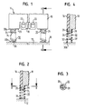
- FIG 1 is schematically one on a steering wheel 10 (of which only one to the Steering wheel hub adjacent area 12 is indicated) attached airbag module 14, which comprises a cover cap 16 and a gas generator carrier 18 Plastic comprises (see also Figure 2).
- the cap 16 surrounds the Gas generator support 18 is substantially complete except for that Area 12 of the steering wheel 10 opposite bottom 20 of the airbag module 14.
- the cap 16 is with the gas generator support 18 over several to the abutting side walls of the gas generator support 18 and the Cover cap 16 provided snap connections 22 connected.
- extensions 24 are formed, which in Point towards the area 12.
- the extensions 24 each sit, as in the FIGS. 2 and 3 can be seen from a projection 26 of the cover cap 16 and a projection 28 of the gas generator carrier 18 together.
- Each extension 24 receives a coil spring 30, which is at its first end 30a Underside of the airbag module and with its second end 30b on one surface supports, which is formed on the region 12 of the steering wheel 10.
- the diameter of a single extension 24 points in relation to the associated coil spring 30 either an oversize or is provided with a corresponding bead (not shown) so that the coil spring 30 is held securely on the extension 24 becomes.
- the coil springs 30 are designed so that they are dynamic Stresses, such as those that can occur in an accident, not from the Extensions 24 slip off or solve in any other way, for example by radial expansion.
- the coil springs30 fulfill a double function. On the one hand, they serve the resetting of the airbag module 14 when triggering a horn signal by pressing the cap 16, the entire module 14 in the direction of Area 12 is depressed. On the other hand, the coil springs 30 secure the connection between cover cap 16 and gas generator support 18. Die Coil springs 30 hold the projections 26 and 28 of the cover cap 16 and of the gas generator carrier 18 together and thus prevent lateral Moving between gas generator carrier 18 and cover cap 16, in particular during an accident. In the direction of the longitudinal axes of the extensions 24 Cover cap 16 through the snap connections 22 on the gas generator support 18 held.
- the coil springs 30 also at their second end 30b on corresponding ones on the steering wheel 10 formed projections 32 securely received, so that the airbag module 14th is attached to the steering wheel 10 solely by the coil springs (30) and the Coil springs 30 alone take control of the airbag module 14.
- the projections 24 provided can also be used to make a horn contact be used.
- the side facing the area 12 is a Extension 24 formed as a contact surface 34. If by depressing the Airbag module 14, the contact surface 34 of the extension 24 and one opposite on the steering wheel 10 or on an extension 32 formed there (FIG. 4) provided contact surface 36 or 36 'are brought into contact with one another, a circuit is closed, which triggers the horn signal.
Landscapes
- Engineering & Computer Science (AREA)
- Mechanical Engineering (AREA)
- Air Bags (AREA)
Abstract
Description
- Figur 1 ein an einem Lenkrad angebrachtes erfindungsgemäßes Airbag-Modul;
- Figur 2 eine Schnittansicht entlang der Linie A-A in Figur 1;
- Figur 3 eine Schnittansicht entlang der Linie B-B in Figur 2; und
- Figur 4 eine Schnittansicht einer Ausführungsvariante entsprechend der Darstellung in Figur 2.
Claims (11)
- Airbag-Modul zum Einbau in ein Lenkrad, mit einem Gasgeneratorträger (18) und einer Abdeckkappe (16), die durch eine Schnappverbindung (22) miteinander verbunden sind, dadurch gekennzeichnet, daß sowohl am Gasgeneratorträger (18) als auch an der Abdeckkappe (16) Vorsprünge (28, 26) ausgebildet sind, wobei jeweils ein Vorsprung (28) des Gasgeneratorträgers (18) und ein Vorsprung (26) der Abdeckkappe (16) einen gemeinsamen Fortsatz (24) bilden, auf dem ein erstes Ende (30a) einer Schraubenfeder (30) aufgenommen ist.
- Airbag-Modul nach Anspruch 1, dadurch gekennzeichnet, daß die Fortsätze (24) an der Unterseite (20) des Airbag-Moduls (14) vorgesehen sind, die einem an die Lenkradnabe angrenzenden Bereich (12) gegenüberliegt.
- Airbag-Modul nach Anspruch 1 oder 2, dadurch gekennzeichnet, daß der Durchmesser der Fortsätze (24) größer als der Innendurchmesser der zugehörigen Schraubenfedern (30) ist.
- Airbag-Modul nach Anspruch 1 oder 2, dadurch gekennzeichnet, daß die Fortsätze (24) einen Wulst aufweisen.
- Airbag-Modul nach einem der vorhergehenden Ansprüche, dadurch gekennzeichnet, daß wenigstens einer der Fortsätze (24) eine Kontaktfläche (34) zur Herstellung eines elektrischen Kontakts aufweist.
- Baugruppe aus einem Lenkrad (10) und einem Airbag-Modul (14) nach einem der vorhergehenden Ansprüche.
- Baugruppe nach Anspruch 6, dadurch gekennzeichnet, daß sich die Schraubenfedern (30) mit ihrem ersten Ende (30a) an der Unterseite (20) des Airbag-Moduls (14) und mit ihrem zweiten Ende (30b) direkt oder indirekt am Lenkrad (10) abstützen.
- Baugruppe nach Anspruch 7, dadurch gekennzeichnet, daß am Lenkrad (10) Fortsätze (32) gebildet sind, auf denen die zweiten Enden (30b) der Schraubenfedern(30) aufgenommen sind.
- Baugruppe nach Anspruch 8, dadurch gekennzeichnet, daß das Airbag-Modul (14) alleine durch die Schraubenfedern (30) am Lenkrad (10) befestigt ist.
- Baugruppe nach Anspruch 8 oder 9, dadurch gekennzeichnet, daß alleine die Schraubenfedern (30) die Führung des Airbag-Moduls (14) gegenüber dem Lenkrad (10) bewirken.
- Baugruppe nach einem der Ansprüche 6 bis 10, dadurch gekennzeichnet, daß am Lenkrad (10) wenigstens eine einem Fortsatz (24) des Airbag-Moduls (14) gegenüberliegende Kontaktfläche (36, 36') gebildet ist.
Applications Claiming Priority (2)
| Application Number | Priority Date | Filing Date | Title |
|---|---|---|---|
| DE20213145U | 2002-08-27 | ||
| DE20213145U DE20213145U1 (de) | 2002-08-27 | 2002-08-27 | Airbag-Modul sowie Baugruppe aus einem Lenkrad und einem Airbag-Modul |
Publications (2)
| Publication Number | Publication Date |
|---|---|
| EP1393992A1 true EP1393992A1 (de) | 2004-03-03 |
| EP1393992B1 EP1393992B1 (de) | 2005-05-25 |
Family
ID=7974462
Family Applications (1)
| Application Number | Title | Priority Date | Filing Date |
|---|---|---|---|
| EP03016656A Expired - Lifetime EP1393992B1 (de) | 2002-08-27 | 2003-07-31 | Airbag-Modul sowie Baugruppe aus einem Lenkrad und einem Airbag-Modul |
Country Status (4)
| Country | Link |
|---|---|
| US (1) | US6883825B2 (de) |
| EP (1) | EP1393992B1 (de) |
| DE (2) | DE20213145U1 (de) |
| ES (1) | ES2242127T3 (de) |
Families Citing this family (4)
| Publication number | Priority date | Publication date | Assignee | Title |
|---|---|---|---|---|
| US6863825B2 (en) | 2003-01-29 | 2005-03-08 | Union Oil Company Of California | Process for removing arsenic from aqueous streams |
| US8066874B2 (en) | 2006-12-28 | 2011-11-29 | Molycorp Minerals, Llc | Apparatus for treating a flow of an aqueous solution containing arsenic |
| US8252087B2 (en) | 2007-10-31 | 2012-08-28 | Molycorp Minerals, Llc | Process and apparatus for treating a gas containing a contaminant |
| US8349764B2 (en) * | 2007-10-31 | 2013-01-08 | Molycorp Minerals, Llc | Composition for treating a fluid |
Citations (4)
| Publication number | Priority date | Publication date | Assignee | Title |
|---|---|---|---|---|
| US5235146A (en) * | 1991-05-29 | 1993-08-10 | Nihon Plast Co., Ltd. | Steering wheel horn switch arrangement |
| GB2270657A (en) * | 1992-08-17 | 1994-03-23 | Autoliv Dev | A steering wheel mounted air-bag unit |
| US5410114A (en) * | 1992-12-25 | 1995-04-25 | Toyoda Gosei Co., Ltd. | Steering wheel horn switch mechanism |
| JPH0958393A (ja) * | 1995-08-24 | 1997-03-04 | Bridgestone Corp | エアバッグ装置 |
Family Cites Families (12)
| Publication number | Priority date | Publication date | Assignee | Title |
|---|---|---|---|---|
| US4785144A (en) * | 1988-02-16 | 1988-11-15 | General Motors Corporation | Horn blowing switch arrangement |
| JP2827547B2 (ja) * | 1991-03-15 | 1998-11-25 | 豊田合成株式会社 | エアバツグ装置付きステアリングホイール |
| US5207544A (en) * | 1992-03-04 | 1993-05-04 | Vsi Corporation | Fastener assembly |
| US5380037A (en) | 1993-10-25 | 1995-01-10 | General Motors Corporation | Snap-in inflatable restraint module mounting mechanism including latch elements |
| US5508482A (en) | 1994-10-11 | 1996-04-16 | General Motors Corporation | Horn activation and steering wheel assembly |
| DE19503816B4 (de) * | 1995-02-06 | 2007-03-22 | Volkswagen Ag | Anordnung zur Befestigung eines aus einem Gehäuseboden und einem Gehäusedeckel bestehenden Gehäuses im Lenkrad |
| US5624130A (en) * | 1995-07-21 | 1997-04-29 | Morton International, Inc. | Air bag inflator for snap-action attachment to a steering wheel |
| DE29805210U1 (de) * | 1998-03-23 | 1998-06-04 | TRW Automotive Safety Systems GmbH, 63743 Aschaffenburg | Aufprall-Schutzvorrichtung |
| GB2339173A (en) * | 1998-07-09 | 2000-01-19 | Ford Global Tech Inc | Steering wheel airbag module attachment |
| US6082758A (en) | 1998-08-17 | 2000-07-04 | General Motors Corporation | Driver air bag horn ground spring |
| DE19927032A1 (de) * | 1999-06-04 | 2000-12-14 | Petri Ag | Anordnung zur Verrastung eines Airbagmoduls mit einem Lenkrad |
| DE10027240B4 (de) | 2000-05-31 | 2016-11-17 | Autoliv Development Ab | Luftsackmodul für Kraftfahrzeuge |
-
2002
- 2002-08-27 DE DE20213145U patent/DE20213145U1/de not_active Expired - Lifetime
-
2003
- 2003-07-31 DE DE50300571T patent/DE50300571D1/de not_active Expired - Fee Related
- 2003-07-31 EP EP03016656A patent/EP1393992B1/de not_active Expired - Lifetime
- 2003-07-31 ES ES03016656T patent/ES2242127T3/es not_active Expired - Lifetime
- 2003-08-08 US US10/637,111 patent/US6883825B2/en not_active Expired - Fee Related
Patent Citations (4)
| Publication number | Priority date | Publication date | Assignee | Title |
|---|---|---|---|---|
| US5235146A (en) * | 1991-05-29 | 1993-08-10 | Nihon Plast Co., Ltd. | Steering wheel horn switch arrangement |
| GB2270657A (en) * | 1992-08-17 | 1994-03-23 | Autoliv Dev | A steering wheel mounted air-bag unit |
| US5410114A (en) * | 1992-12-25 | 1995-04-25 | Toyoda Gosei Co., Ltd. | Steering wheel horn switch mechanism |
| JPH0958393A (ja) * | 1995-08-24 | 1997-03-04 | Bridgestone Corp | エアバッグ装置 |
Non-Patent Citations (1)
| Title |
|---|
| PATENT ABSTRACTS OF JAPAN vol. 1997, no. 07 31 July 1997 (1997-07-31) * |
Also Published As
| Publication number | Publication date |
|---|---|
| ES2242127T3 (es) | 2005-11-01 |
| US6883825B2 (en) | 2005-04-26 |
| EP1393992B1 (de) | 2005-05-25 |
| US20040041378A1 (en) | 2004-03-04 |
| DE50300571D1 (de) | 2005-06-30 |
| DE20213145U1 (de) | 2003-01-09 |
Similar Documents
| Publication | Publication Date | Title |
|---|---|---|
| DE4317737C2 (de) | Lenkradpolster | |
| EP1197402B1 (de) | Fahrzeuglenkrad | |
| EP2121390B1 (de) | Folienplakette für eine airbagabdeckung | |
| EP0945311B1 (de) | Aufprall-Schutzvorrichtung | |
| EP2057043A1 (de) | Vorrichtung zur befestigung einer airbageinheit in einer baugruppe eines kraftfahrzeugs, insbesondere in einem lenkrad, durch verrasten | |
| DE4242157B4 (de) | Modulabdeckung für ein Airbagsystem | |
| EP1068095A1 (de) | Haltegriffkonsole und baugruppe aus haltegriffkonsole und kopf-seitengassack-modul | |
| DE3328386A1 (de) | Hochfrequenzdichte abschirmung von flaechenteilen | |
| DE2935936C2 (de) | Lenkrad für Kraftwagen | |
| EP1426248B1 (de) | Gassackmodul | |
| EP1393992B1 (de) | Airbag-Modul sowie Baugruppe aus einem Lenkrad und einem Airbag-Modul | |
| EP1716012A1 (de) | Komponente, insbesondere sonnenblende und insbesondere für ein fahrzeug, verfahren zur herstellung einer komponente | |
| EP0618110A1 (de) | Armaturentafel mit Beifahrer-Airbag | |
| DE20307096U1 (de) | Baugruppe aus einem Lenkrad und einem Gassackmodul | |
| DE60102092T2 (de) | Schaltereinheit für ein Lenkrad in einem Kraftfahrzeug | |
| DE69020932T2 (de) | Lenkrad-Hupenschaltermechanismus. | |
| DE19704554A1 (de) | Drehverbinder-Befestigungskonstruktion | |
| EP1790536B1 (de) | Fahrzeuglenkrad mit Airbag und gedämpftem Hupenschalter | |
| DE102008000224A1 (de) | Gassackmodul mit Hupvorrichtung | |
| DE20106693U1 (de) | Gassackmodul | |
| DE102017101227B3 (de) | Airbag-Gehäuseeinrichtung mit Kopplungselementen | |
| DE69405849T2 (de) | Fahrzeuglenksäulen-Anordnungen | |
| DE102018102755A1 (de) | Gassackmodul, Verfahren zur Herstellung eines Gassackmoduls und Lenkrad | |
| DE102021113991A1 (de) | Anordnung und Verfahren zum Herstellen einer Anordnung für ein Fahrzeugdach für ein Kraftfahrzeug | |
| DE69505816T2 (de) | Infrarot-detektor und verfahren zu seiner herstellung |
Legal Events
| Date | Code | Title | Description |
|---|---|---|---|
| PUAI | Public reference made under article 153(3) epc to a published international application that has entered the european phase |
Free format text: ORIGINAL CODE: 0009012 |
|
| AK | Designated contracting states |
Kind code of ref document: A1 Designated state(s): AT BE BG CH CY CZ DE DK EE ES FI FR GB GR HU IE IT LI LU MC NL PT RO SE SI SK TR |
|
| AX | Request for extension of the european patent |
Extension state: AL LT LV MK |
|
| 17P | Request for examination filed |
Effective date: 20040803 |
|
| GRAP | Despatch of communication of intention to grant a patent |
Free format text: ORIGINAL CODE: EPIDOSNIGR1 |
|
| AKX | Designation fees paid |
Designated state(s): DE ES FR GB IT |
|
| GRAS | Grant fee paid |
Free format text: ORIGINAL CODE: EPIDOSNIGR3 |
|
| GRAA | (expected) grant |
Free format text: ORIGINAL CODE: 0009210 |
|
| AK | Designated contracting states |
Kind code of ref document: B1 Designated state(s): DE ES FR GB IT |
|
| REG | Reference to a national code |
Ref country code: GB Ref legal event code: FG4D Free format text: NOT ENGLISH |
|
| REG | Reference to a national code |
Ref country code: IE Ref legal event code: FG4D Free format text: LANGUAGE OF EP DOCUMENT: GERMAN |
|
| REF | Corresponds to: |
Ref document number: 50300571 Country of ref document: DE Date of ref document: 20050630 Kind code of ref document: P |
|
| GBT | Gb: translation of ep patent filed (gb section 77(6)(a)/1977) |
Effective date: 20050725 |
|
| REG | Reference to a national code |
Ref country code: ES Ref legal event code: FG2A Ref document number: 2242127 Country of ref document: ES Kind code of ref document: T3 |
|
| ET | Fr: translation filed | ||
| PLBE | No opposition filed within time limit |
Free format text: ORIGINAL CODE: 0009261 |
|
| STAA | Information on the status of an ep patent application or granted ep patent |
Free format text: STATUS: NO OPPOSITION FILED WITHIN TIME LIMIT |
|
| 26N | No opposition filed |
Effective date: 20060228 |
|
| PGFP | Annual fee paid to national office [announced via postgrant information from national office to epo] |
Ref country code: ES Payment date: 20070713 Year of fee payment: 5 |
|
| PGFP | Annual fee paid to national office [announced via postgrant information from national office to epo] |
Ref country code: IT Payment date: 20070714 Year of fee payment: 5 |
|
| GBPC | Gb: european patent ceased through non-payment of renewal fee |
Effective date: 20070731 |
|
| PGFP | Annual fee paid to national office [announced via postgrant information from national office to epo] |
Ref country code: FR Payment date: 20070706 Year of fee payment: 5 |
|
| PG25 | Lapsed in a contracting state [announced via postgrant information from national office to epo] |
Ref country code: GB Free format text: LAPSE BECAUSE OF NON-PAYMENT OF DUE FEES Effective date: 20070731 |
|
| PGFP | Annual fee paid to national office [announced via postgrant information from national office to epo] |
Ref country code: DE Payment date: 20080731 Year of fee payment: 6 |
|
| REG | Reference to a national code |
Ref country code: FR Ref legal event code: ST Effective date: 20090331 |
|
| PG25 | Lapsed in a contracting state [announced via postgrant information from national office to epo] |
Ref country code: IT Free format text: LAPSE BECAUSE OF NON-PAYMENT OF DUE FEES Effective date: 20080731 Ref country code: FR Free format text: LAPSE BECAUSE OF NON-PAYMENT OF DUE FEES Effective date: 20080731 |
|
| REG | Reference to a national code |
Ref country code: ES Ref legal event code: FD2A Effective date: 20080801 |
|
| PG25 | Lapsed in a contracting state [announced via postgrant information from national office to epo] |
Ref country code: ES Free format text: LAPSE BECAUSE OF NON-PAYMENT OF DUE FEES Effective date: 20080801 |
|
| PG25 | Lapsed in a contracting state [announced via postgrant information from national office to epo] |
Ref country code: DE Free format text: LAPSE BECAUSE OF NON-PAYMENT OF DUE FEES Effective date: 20100202 |