EP1393956A1 - Antriebsaggregat - Google Patents
Antriebsaggregat Download PDFInfo
- Publication number
- EP1393956A1 EP1393956A1 EP03012358A EP03012358A EP1393956A1 EP 1393956 A1 EP1393956 A1 EP 1393956A1 EP 03012358 A EP03012358 A EP 03012358A EP 03012358 A EP03012358 A EP 03012358A EP 1393956 A1 EP1393956 A1 EP 1393956A1
- Authority
- EP
- European Patent Office
- Prior art keywords
- drive
- differential
- shaft
- intermediate shaft
- output shaft
- Prior art date
- Legal status (The legal status is an assumption and is not a legal conclusion. Google has not performed a legal analysis and makes no representation as to the accuracy of the status listed.)
- Granted
Links
Images

Classifications
-
- B—PERFORMING OPERATIONS; TRANSPORTING
- B60—VEHICLES IN GENERAL
- B60K—ARRANGEMENT OR MOUNTING OF PROPULSION UNITS OR OF TRANSMISSIONS IN VEHICLES; ARRANGEMENT OR MOUNTING OF PLURAL DIVERSE PRIME-MOVERS IN VEHICLES; AUXILIARY DRIVES FOR VEHICLES; INSTRUMENTATION OR DASHBOARDS FOR VEHICLES; ARRANGEMENTS IN CONNECTION WITH COOLING, AIR INTAKE, GAS EXHAUST OR FUEL SUPPLY OF PROPULSION UNITS IN VEHICLES
- B60K17/00—Arrangement or mounting of transmissions in vehicles
- B60K17/04—Arrangement or mounting of transmissions in vehicles characterised by arrangement, location or kind of gearing
- B60K17/16—Arrangement or mounting of transmissions in vehicles characterised by arrangement, location or kind of gearing of differential gearing
-
- B—PERFORMING OPERATIONS; TRANSPORTING
- B60—VEHICLES IN GENERAL
- B60K—ARRANGEMENT OR MOUNTING OF PROPULSION UNITS OR OF TRANSMISSIONS IN VEHICLES; ARRANGEMENT OR MOUNTING OF PLURAL DIVERSE PRIME-MOVERS IN VEHICLES; AUXILIARY DRIVES FOR VEHICLES; INSTRUMENTATION OR DASHBOARDS FOR VEHICLES; ARRANGEMENTS IN CONNECTION WITH COOLING, AIR INTAKE, GAS EXHAUST OR FUEL SUPPLY OF PROPULSION UNITS IN VEHICLES
- B60K17/00—Arrangement or mounting of transmissions in vehicles
- B60K17/22—Arrangement or mounting of transmissions in vehicles characterised by arrangement, location, or type of main drive shafting, e.g. cardan shaft
-
- B—PERFORMING OPERATIONS; TRANSPORTING
- B60—VEHICLES IN GENERAL
- B60K—ARRANGEMENT OR MOUNTING OF PROPULSION UNITS OR OF TRANSMISSIONS IN VEHICLES; ARRANGEMENT OR MOUNTING OF PLURAL DIVERSE PRIME-MOVERS IN VEHICLES; AUXILIARY DRIVES FOR VEHICLES; INSTRUMENTATION OR DASHBOARDS FOR VEHICLES; ARRANGEMENTS IN CONNECTION WITH COOLING, AIR INTAKE, GAS EXHAUST OR FUEL SUPPLY OF PROPULSION UNITS IN VEHICLES
- B60K17/00—Arrangement or mounting of transmissions in vehicles
- B60K17/34—Arrangement or mounting of transmissions in vehicles for driving both front and rear wheels, e.g. four wheel drive vehicles
- B60K17/348—Arrangement or mounting of transmissions in vehicles for driving both front and rear wheels, e.g. four wheel drive vehicles having differential means for driving one set of wheels, e.g. the front, at one speed and the other set, e.g. the rear, at a different speed
Definitions
- the invention relates to a drive unit, in particular for Motor vehicles, according to the preamble of claim 1.
- a generic drive unit for motor vehicles shows EP 0 183 051 A1, in which the force flow behind the Speed change gear lying axle differential laterally positioned next to the drive source or the internal combustion engine is.
- the output shaft of the gearbox is over a spur gear with a rotatably mounted intermediate gear drivingly with an input gear of the differential drive shaft connected.
- the object of the invention is to provide a drive unit of the generic type To propose kind, the structurally simpler, more compact and in terms of efficiency is more favorable.
- the intermediate drive is formed by an intermediate shaft which carries two gears, one of which is connected to the output shaft of the transmission and the other with the at the differential housing of the axle differential arranged drive wheel (spur or ring gear) in Intervention is.
- the proposed intermediate drive is structurally simpler and more compact, since he only gets by with two teeth, while In the prior art, three tooth interventions are required. from that also results in a cheaper transmission efficiency with less manufacturing technical effort.
- the Intermediate according to the invention particularly favorable in the adjacent Area for the drive source or internal combustion engine Arrange.
- the differential measure can be significantly reduced, d. H. even though the solution according to the invention on the transmission side (and not geared) is arranged there succeeds a closer to the engine arrangement of Differential shaft in the previous, front gearbox.
- the Differential measure represents the distance between the center of the differential shaft and the engine-transmission flange.
- the intermediate shaft may be at least substantially parallel to Output shaft of the transmission and arranged with this be connected via a spur gear drive. That remains that Achsdifferenzial essentially conventional design at Longitudinal arrangement of the drive unit; i.e. with a cone drive trained drive pinion on the intermediate shaft and a correspondingly toothed crown wheel on the differential housing of the differential.
- the intermediate shaft can be particularly advantageous at least essentially transversely to said output shaft of the transmission arranged and with the output shaft via a bevel gear be connected by love. Accordingly, the gearing the Achsedifferenziales a manufacturing technology cheaper Bevel gear teeth while the required bevel gearing positioned at the output shaft of the transmission is and because of the then smaller dimensions and possibly simpler Gear parameters (no hypoid gear) also is cheaper to manufacture.
- the intermediate shaft and the differential are arranged so that the wheels of the motor vehicle driving drive shafts in the vertical Projection seen between the drive source and a Torque transmission means positioned to change gearbox are.
- the one longer drive shaft can then below the power output shaft of the drive source - in the case of an internal combustion engine the crankshaft - be positioned so that the required Clearance despite low aggregate arrangement in the motor vehicle is guaranteed.
- the drive shaft immediately behind the torque transmission means be arranged.
- the torque transmitting means may be a friction clutch and / or a torque converter and / or a starter-generator device and / or two-mass flywheel be, wherein said drive shaft at also connected in series with several transmission means can be positioned between these transmission means, so particularly advantageous between a starter-generator device (also known as ISG) and a downstream, possibly also automated main clutch (wet or dry friction clutch) of the motor vehicle.
- the differential and / or the intermediate shaft can also be structurally advantageously in the housing of the transmission be integrated.
- This form in known manner that Change gear and the axle differential with the intermediate shaft a structural unit with the drive source, in particular a Internal combustion engine, to the drive unit fauxhegbar is.
- the differential and the intermediate shaft in a housing be arranged as an alternative module to a differential without intermediate shaft and with a bevel gear can be flanged to the housing of the transmission.
- a bevel gear can be flanged to the housing of the transmission.
- the front axle load succeeds due to shortening to reduce the differential measure.
- the invention allows a degree of freedom with respect to a variation in the height arrangement by Pivotability in the spinal drive is structurally possible.
- Fig. 1 10 denotes a drive unit, which is composed essentially of an internal combustion engine 12 as a drive source, a speed change gear 14 and an axle differential 16 for driving the front wheels, not shown, of the motor vehicle.
- the mentioned units of conventional design Thus, the change gear 14, a manual transmission or an automatic transmission and the differential 16 may be a bevel gear differential.
- the drive unit 10 is arranged for example on the front side of the motor vehicle in the longitudinal installation.
- the change gear 14 has an input shaft 18 which in the only indicated gear housing 20 is rotatably mounted and the via a main clutch 22 with the power output shaft 24th (Crankshaft) of the internal combustion engine 12 is drivingly connected.
- an output shaft 26 of the transmission 14 via an intermediate drive or spur gear 28 with the gears 30, 32 with a parallel to the output shaft 26 positioned intermediate shaft 34 in engagement, wherein the intermediate shaft 34 on the other a drive pinion 36 carries, which in turn directly with the differential housing 38 fixed ring gear 40 of the Achsedifferenziales 16 drives.
- the gearing between the Drive pinion 36 and the ring gear 40 is in a known manner Cone drive with hypoid toothing.
- the intermediate shaft 34 and the differential 16 are in a housing portion 20 a arranged and stored, in not shown Manner via a flange formation with the housing 20th can be connected to a unit.
- the flange training can identical to a flange design of a conventional Achsdifferenziales be without intermediate shaft 34, wherein the ring gear 40 in a known manner directly with the on the output shaft 26 of the transmission 14 then provided drive pinion 36 is engaged.
- the axle differential 16 can be positioned so that the transverse drive shafts 42, 44 seen in plan view between the internal combustion engine 12 and at the power output shaft or crankshaft 24 and flanged thereto Main coupling 22 extend as torque transmitting means and thus viewed in the vertical direction relatively close to the rotational center axis the power output shaft 24 are positionable (this concerns in particular the longer, the power output shaft 24 crossing Drive shaft 42).
- This allows the drive unit 10 for Achieving a flat, aerodynamically favorable stem of the Motor vehicle can be arranged relatively low.
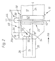
- Fig. 2 are functionally identical parts with the same reference numerals as shown in FIG. 1. The execution according to FIG. 2 is described only to the extent that it differs significantly from FIG. 1 deviates.
- Bevel gear 50 attached, which is part of an intermediate drive or bevel gear 52 with another bevel gear 54 is.
- the bevel gear 54 is seated on the intermediate shaft 34 ', which in the Top view seen transverse to the vehicle longitudinal direction and perpendicular to the output shaft 26 extends.
- the toothing of the bevel gear 52 may be designed as Hypoidvertechnikung, in the the axis of rotation of the output shaft 26 is lower than the axis of rotation the intermediate shaft 34 '.
- the intermediate shaft 34 in turn carries a spur gear 56, the as part of the spur gear 60 with the spur gear 58 on the differential housing 38 of the axle differential 16 meshes.
- the arrangement of the intermediate drive 52, 34 'and 60 is with regard to the selected translations, the gear diameter and the Center distances so that the drive shafts 42, 44 in plan view seen between a starter-generator means 62nd (ISG) and the main clutch 22 run.
- a powder magnetic coupling etc. may be provided instead of the Main clutch 22 as torque transmitting means also on hydraulic torque converter.
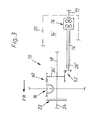
- a drive unit 70 is shown for an all-wheel drive of a motor vehicle, which is also described only insofar as it differs significantly from the previous two embodiments. Identical parts are provided with the same reference numerals.
- the change gear 14 ' has two output shafts 26' and 72 on, from a hollow shaft 74 and via an inter-axle differential 76 e.g. the Torsenbauart are driven.
- the output shaft 72 drives in a known manner via a not illustrated propeller shaft a rear differential of the motor vehicle while the forward-ending output shaft 26 'via the intermediate drive 52, 34', 60 (see also Fig. 2) the front axle differential 16 drives.
- the main clutch 22 is present in this embodiment the axle differential 16, however, the arrangement can also as in the above embodiments according to FIGS. 1 and 2 described be.
- the intermediate shaft 34, 34 ' also be positioned obliquely to the output shaft 26.
Landscapes
- Engineering & Computer Science (AREA)
- Chemical & Material Sciences (AREA)
- Combustion & Propulsion (AREA)
- Transportation (AREA)
- Mechanical Engineering (AREA)
- Retarders (AREA)
- Hybrid Electric Vehicles (AREA)
- Motor Power Transmission Devices (AREA)
- Arrangement And Driving Of Transmission Devices (AREA)
Abstract
Description
Claims (12)
- Antriebsaggregat, insbesondere für Kraftfahrzeuge, mit einer Antriebsquelle, einem nachgeschaltetem Geschwindigkeits-Wechselgetriebe und einem Achsdifferenzial, wobei das Achsdifferenzial über einen der Antriebsquelle benachbarten Zwischentrieb seitlich versetzt zur Ausgangswelle des Wechselgetriebes angeordnet ist, dadurch gekennzeichnet, dass der Zwischentrieb (28, 34; 52, 34') durch eine Zwischenwelle (34) gebildet ist, die zwei Zahnräder (32, 36; 54, 56) trägt, von denen eines mit der Ausgangswelle (26) des Wechselgetriebes (14) und das andere mit dem am Ausgleichsgehäuse (38) des Differenziales (16) angeordnetem Antriebsrad (Stirnrad 58 oder Tellerrad 40) in Eingriff ist.
- Antriebsaggregat nach Anspruch 1, dadurch gekennzeichnet, dass die Zwischenwelle (34') zumindest im wesentlichen quer zur besagten Ausgangswelle (26) des Wechselgetriebes (14) angeordnet und mit dieser über einen Kegeltrieb (52) trieblich verbunden ist.
- Antriebsaggregat nach den Ansprüchen 1 und 2, dadurch gekennzeichnet, dass die Zwischenwelle (34') abtriebsseitig über einen Stirnradtrieb (60) mit dem Ausgleichsgehäuse (38) des Differenziales (16) zusammenwirkt.
- Antriebsaggregat nach Anspruch 1, dadurch gekennzeichnet, dass die Zwischenwelle (34) zumindest im wesentlichen parallel zur Ausgangswelle (26) des Wechselgetriebes (14) angeordnet und mit dieser über einen Stirnradtrieb (28) trieblich verbunden ist.
- Antriebsaggregat nach einem oder mehreren der vorhergehenden Ansprüche, dadurch gekennzeichnet, dass die Antriebswelle (42) unmittelbar hinter dem Drehmoment-Übertragungsmittel (22) anordenbar ist.
- Antriebsaggregat nach Anspruch 5, dadurch gekennzeichnet, dass das Übertragungsmittel eine Reibungskupplung (22) und/oder ein Zwei-Massen-Schwungrad und/oder ein Drehmomentwandler und/oder eine Starter-Generator-Vorrichtung (62) ist.
- Antriebsaggregat nach den Ansprüchen 5 und 6, dadurch gekennzeichnet, dass die Antriebswellen (42, 44) des Differenziales (16) zwischen einer Starter-Generator-Vorrichtung (62) und einer nachgeschalteten Reibungskupplung (22) positioniert sind.
- Antriebsaggregat nach einem oder mehreren der Ansprüche 1 bis 4, dadurch gekennzeichnet, dass die Zwischenwelle (34) und das Differenzial (16) so angeordnet sind, dass die die Räder des Kraftfahrzeuges antreibenden Antriebswellen (42, 44) in der senkrechten Projektion gesehen zwischen der Antriebsquelle (12) und einem Drehmoment-Übertragungsmittel (22, 62) zum Wechselgetriebe (14) positioniert sind.
- Antriebsaggregat nach einem oder mehreren der Ansprüche 1 bis 7, dadurch gekennzeichnet, dass das Differenzial (14) und/oder die Zwischenwelle (34) in das Gehäuse (20) des Wechselgetriebes (14) integriert sind.
- Antriebsaggregat nach einem oder mehreren der vorhergehenden Ansprüche, dadurch gekennzeichnet, dass das Differenzial (14) und die Zwischenwelle (34) in einem Gehäuse (20a) angeordnet sind, das als alternatives Modul zu einem Getriebe ohne Zwischenwelle an das Gehäuse (20) nach Figuren 2 und 3 des Wechselgetriebes (14) anflanschbar ist.
- Antriebsaggregat nach einem oder mehreren der vorhergehenden Ansprüche, dadurch gekennzeichnet, dass das Wechselgetriebe (14') zwei koaxial oder parallel zueinander angeordnete Ausgangswellen (26',72) mit einem dazwischengeschaltetem Längsausgleich (Zwischenachsdifferenzial 76) aufweist und dass die mit der Zwischenwelle (34') trieblich verbundene Ausgangswelle (26') eine von zwei angetriebenen Achsen antreibt.
- Antriebsaggregat nach einem oder mehreren der vorhergehenden Ansprüche, dadurch gekennzeichnet, dass das Vorderachsdifferenzial mit den Antriebswellen (42, 44) durch Verschwenken im Stirnbereich in ihrer Höhe konstruktiv variierbar ist.
Applications Claiming Priority (2)
| Application Number | Priority Date | Filing Date | Title |
|---|---|---|---|
| DE10238664 | 2002-08-23 | ||
| DE2002138664 DE10238664A1 (de) | 2002-08-23 | 2002-08-23 | Antriebsaggregat |
Publications (2)
| Publication Number | Publication Date |
|---|---|
| EP1393956A1 true EP1393956A1 (de) | 2004-03-03 |
| EP1393956B1 EP1393956B1 (de) | 2008-06-04 |
Family
ID=31197280
Family Applications (1)
| Application Number | Title | Priority Date | Filing Date |
|---|---|---|---|
| EP20030012358 Expired - Lifetime EP1393956B1 (de) | 2002-08-23 | 2003-05-30 | Antriebsaggregat |
Country Status (2)
| Country | Link |
|---|---|
| EP (1) | EP1393956B1 (de) |
| DE (2) | DE10238664A1 (de) |
Families Citing this family (2)
| Publication number | Priority date | Publication date | Assignee | Title |
|---|---|---|---|---|
| DE102005014622B4 (de) * | 2005-03-23 | 2007-07-05 | Getrag Getriebe- Und Zahnradfabrik Hermann Hagenmeyer Gmbh & Cie Kg | Antriebsstrang für ein Kraftfahrzeug |
| DE102007031011B4 (de) | 2007-07-04 | 2019-07-11 | Audi Ag | Antriebsstrang für ein Kraftfahrzeug |
Citations (5)
| Publication number | Priority date | Publication date | Assignee | Title |
|---|---|---|---|---|
| US4258587A (en) * | 1977-02-14 | 1981-03-31 | Toyota Jidosha Kogyo Kabushiki Kaisha | Power transmission unit for an automotive vehicle |
| DE3921414A1 (de) * | 1988-06-29 | 1990-01-04 | Honda Motor Co Ltd | Antriebssystem fuer ein fahrzeug |
| US5205373A (en) * | 1990-03-09 | 1993-04-27 | Mazda Motor Corporation | Structure of vehicle power train |
| DE19515686A1 (de) * | 1994-05-10 | 1995-11-16 | Volkswagen Ag | Antriebsvorrichtung eines Kraftfahrzeuges |
| US5632354A (en) * | 1993-09-16 | 1997-05-27 | Fuji Jukogyo Kabushiki Kaisha | Motor vehicle with a continuously variable transmission |
Family Cites Families (8)
| Publication number | Priority date | Publication date | Assignee | Title |
|---|---|---|---|---|
| FR2128973A5 (de) * | 1971-03-10 | 1972-10-27 | Peugeot & Renault | |
| CH603378A5 (de) * | 1976-06-02 | 1978-08-15 | Schilter Maschinenfabrik Ag | |
| FR2403227A1 (fr) * | 1977-09-14 | 1979-04-13 | Renault | Transmission pour groupe moto-propulseur de vehicule automobile a boite de vitesses mecanique ou automatique |
| EP0183051A1 (de) * | 1984-10-26 | 1986-06-04 | Nissan Motor Co., Ltd. | Kraftübertragungssystem für Kraftfahrzeuge |
| JPH01156131A (ja) * | 1987-12-11 | 1989-06-19 | Honda Motor Co Ltd | 自動車用終減速機 |
| DE19505027C1 (de) * | 1995-02-15 | 1996-10-02 | Fichtel & Sachs Ag | Parallelhybridantrieb für ein Kraftfahrzeug |
| FR2735727B1 (fr) * | 1995-06-22 | 1997-08-14 | Peugeot | Groupe moto-propulseur pour vehicule a moteur dispose longitudinalement |
| JP3637111B2 (ja) * | 1995-08-11 | 2005-04-13 | 富士重工業株式会社 | 車両用パワユニットのトランスミッション締結部構造 |
-
2002
- 2002-08-23 DE DE2002138664 patent/DE10238664A1/de not_active Ceased
-
2003
- 2003-05-30 DE DE50309944T patent/DE50309944D1/de not_active Expired - Lifetime
- 2003-05-30 EP EP20030012358 patent/EP1393956B1/de not_active Expired - Lifetime
Patent Citations (5)
| Publication number | Priority date | Publication date | Assignee | Title |
|---|---|---|---|---|
| US4258587A (en) * | 1977-02-14 | 1981-03-31 | Toyota Jidosha Kogyo Kabushiki Kaisha | Power transmission unit for an automotive vehicle |
| DE3921414A1 (de) * | 1988-06-29 | 1990-01-04 | Honda Motor Co Ltd | Antriebssystem fuer ein fahrzeug |
| US5205373A (en) * | 1990-03-09 | 1993-04-27 | Mazda Motor Corporation | Structure of vehicle power train |
| US5632354A (en) * | 1993-09-16 | 1997-05-27 | Fuji Jukogyo Kabushiki Kaisha | Motor vehicle with a continuously variable transmission |
| DE19515686A1 (de) * | 1994-05-10 | 1995-11-16 | Volkswagen Ag | Antriebsvorrichtung eines Kraftfahrzeuges |
Also Published As
| Publication number | Publication date |
|---|---|
| EP1393956B1 (de) | 2008-06-04 |
| DE50309944D1 (de) | 2008-07-17 |
| DE10238664A1 (de) | 2004-04-22 |
Similar Documents
| Publication | Publication Date | Title |
|---|---|---|
| EP2608995B1 (de) | Antriebseinrichtung für einen triebwagen | |
| DE4119387C2 (de) | Antriebseinrichtung für ein Kraftfahrzeug | |
| DE10162337B4 (de) | Längs eingebauter Antriebsstrang | |
| DE102010040883A1 (de) | Verteilergetriebe | |
| DE2422779C3 (de) | Antriebsblock für Kraftfahrzeuge | |
| EP1634756B1 (de) | Antriebseinrichtung | |
| EP2248699B1 (de) | Antriebsstrang eines Kraftfahrzeuges umfassend ein Stufenlos-Getriebe | |
| DE102011018865B4 (de) | Antriebsvorrichtung für ein front-, heck- oder allradgetriebenes Kraftfahrzeug | |
| DE102013222086A1 (de) | Antriebsstrang für ein Schienenfahrzeug | |
| EP1393956B1 (de) | Antriebsaggregat | |
| DE2904062A1 (de) | Flaches automatisches getriebe | |
| DE102007031011B4 (de) | Antriebsstrang für ein Kraftfahrzeug | |
| EP2248697B1 (de) | Antriebsstrang eines Kraftfahrzeuges | |
| EP0648638B1 (de) | Antriebskombination | |
| DE102006043048A1 (de) | Antriebsanordnung für allradgetriebene Kraftfahrzeuge | |
| DE4111983B4 (de) | Antriebseinheit für ein Fahrzeug | |
| DE69814784T2 (de) | Antriebsstranganordnung | |
| DE102009014565A1 (de) | Fahrzeuggetriebe | |
| WO2004096596A1 (de) | Antriebsaggregat für kraftfahrzeuge | |
| DE102008048680B4 (de) | Antriebsanordnung für Kraftfahrzeuge mit Allradantrieb | |
| DE10308767A1 (de) | Antriebseinheit für ein Kraftfahrzeug | |
| DE1179130B (de) | Antrieb fuer Amphibienfahrzeuge | |
| EP4023480A2 (de) | Getriebe und landwirtschaftliches oder industrielles nutzfahrzeug | |
| EP0647191B1 (de) | Antrieb für motorgetriebene strassenfahrzeuge, insbes. pkw sowie getriebeanordnung für einen solchen antrieb | |
| DE2433566C3 (de) | Triebwerk für einen knickgelenkten Schlepper |
Legal Events
| Date | Code | Title | Description |
|---|---|---|---|
| PUAI | Public reference made under article 153(3) epc to a published international application that has entered the european phase |
Free format text: ORIGINAL CODE: 0009012 |
|
| 17P | Request for examination filed |
Effective date: 20031212 |
|
| AK | Designated contracting states |
Kind code of ref document: A1 Designated state(s): AT BE BG CH CY CZ DE DK EE ES FI FR GB GR HU IE IT LI LU MC NL PT RO SE SI SK TR |
|
| AX | Request for extension of the european patent |
Extension state: AL LT LV MK |
|
| 17Q | First examination report despatched |
Effective date: 20040506 |
|
| AKX | Designation fees paid |
Designated state(s): DE FR GB IT |
|
| 17Q | First examination report despatched |
Effective date: 20040506 |
|
| GRAP | Despatch of communication of intention to grant a patent |
Free format text: ORIGINAL CODE: EPIDOSNIGR1 |
|
| GRAS | Grant fee paid |
Free format text: ORIGINAL CODE: EPIDOSNIGR3 |
|
| GRAA | (expected) grant |
Free format text: ORIGINAL CODE: 0009210 |
|
| AK | Designated contracting states |
Kind code of ref document: B1 Designated state(s): DE FR GB IT |
|
| REG | Reference to a national code |
Ref country code: GB Ref legal event code: FG4D Free format text: NOT ENGLISH |
|
| REF | Corresponds to: |
Ref document number: 50309944 Country of ref document: DE Date of ref document: 20080717 Kind code of ref document: P |
|
| ET | Fr: translation filed | ||
| PLBE | No opposition filed within time limit |
Free format text: ORIGINAL CODE: 0009261 |
|
| STAA | Information on the status of an ep patent application or granted ep patent |
Free format text: STATUS: NO OPPOSITION FILED WITHIN TIME LIMIT |
|
| 26N | No opposition filed |
Effective date: 20090305 |
|
| REG | Reference to a national code |
Ref country code: FR Ref legal event code: PLFP Year of fee payment: 14 |
|
| REG | Reference to a national code |
Ref country code: FR Ref legal event code: PLFP Year of fee payment: 15 |
|
| REG | Reference to a national code |
Ref country code: FR Ref legal event code: PLFP Year of fee payment: 16 |
|
| PGFP | Annual fee paid to national office [announced via postgrant information from national office to epo] |
Ref country code: DE Payment date: 20200531 Year of fee payment: 18 Ref country code: FR Payment date: 20200523 Year of fee payment: 18 |
|
| PGFP | Annual fee paid to national office [announced via postgrant information from national office to epo] |
Ref country code: GB Payment date: 20200528 Year of fee payment: 18 Ref country code: IT Payment date: 20200529 Year of fee payment: 18 |
|
| REG | Reference to a national code |
Ref country code: DE Ref legal event code: R119 Ref document number: 50309944 Country of ref document: DE |
|
| GBPC | Gb: european patent ceased through non-payment of renewal fee |
Effective date: 20210530 |
|
| PG25 | Lapsed in a contracting state [announced via postgrant information from national office to epo] |
Ref country code: GB Free format text: LAPSE BECAUSE OF NON-PAYMENT OF DUE FEES Effective date: 20210530 Ref country code: DE Free format text: LAPSE BECAUSE OF NON-PAYMENT OF DUE FEES Effective date: 20211201 |
|
| PG25 | Lapsed in a contracting state [announced via postgrant information from national office to epo] |
Ref country code: FR Free format text: LAPSE BECAUSE OF NON-PAYMENT OF DUE FEES Effective date: 20210531 |
|
| PG25 | Lapsed in a contracting state [announced via postgrant information from national office to epo] |
Ref country code: IT Free format text: LAPSE BECAUSE OF NON-PAYMENT OF DUE FEES Effective date: 20200530 |
|
| PG25 | Lapsed in a contracting state [announced via postgrant information from national office to epo] |
Ref country code: IT Free format text: LAPSE BECAUSE OF NON-PAYMENT OF DUE FEES Effective date: 20210530 |