EP1393903A2 - Presse rotative pour rapporter des motifs sur un substrat en bande - Google Patents
Presse rotative pour rapporter des motifs sur un substrat en bande Download PDFInfo
- Publication number
- EP1393903A2 EP1393903A2 EP03017465A EP03017465A EP1393903A2 EP 1393903 A2 EP1393903 A2 EP 1393903A2 EP 03017465 A EP03017465 A EP 03017465A EP 03017465 A EP03017465 A EP 03017465A EP 1393903 A2 EP1393903 A2 EP 1393903A2
- Authority
- EP
- European Patent Office
- Prior art keywords
- support
- strip
- press according
- speed
- substrate
- Prior art date
- Legal status (The legal status is an assumption and is not a legal conclusion. Google has not performed a legal analysis and makes no representation as to the accuracy of the status listed.)
- Granted
Links
Images



Classifications
-
- B—PERFORMING OPERATIONS; TRANSPORTING
- B41—PRINTING; LINING MACHINES; TYPEWRITERS; STAMPS
- B41F—PRINTING MACHINES OR PRESSES
- B41F19/00—Apparatus or machines for carrying out printing operations combined with other operations
- B41F19/02—Apparatus or machines for carrying out printing operations combined with other operations with embossing
- B41F19/06—Printing and embossing between a negative and a positive forme after inking and wiping the negative forme; Printing from an ink band treated with colour or "gold"
- B41F19/062—Presses of the rotary type
-
- B—PERFORMING OPERATIONS; TRANSPORTING
- B41—PRINTING; LINING MACHINES; TYPEWRITERS; STAMPS
- B41F—PRINTING MACHINES OR PRESSES
- B41F13/00—Common details of rotary presses or machines
- B41F13/02—Conveying or guiding webs through presses or machines
- B41F13/04—Conveying or guiding webs through presses or machines intermittently
-
- B—PERFORMING OPERATIONS; TRANSPORTING
- B41—PRINTING; LINING MACHINES; TYPEWRITERS; STAMPS
- B41F—PRINTING MACHINES OR PRESSES
- B41F13/00—Common details of rotary presses or machines
- B41F13/0008—Driving devices
-
- B—PERFORMING OPERATIONS; TRANSPORTING
- B41—PRINTING; LINING MACHINES; TYPEWRITERS; STAMPS
- B41F—PRINTING MACHINES OR PRESSES
- B41F13/00—Common details of rotary presses or machines
- B41F13/008—Mechanical features of drives, e.g. gears, clutches
Definitions
- the present invention relates to a rotary press for reporting patterns on a strip substrate, comprising means for driving longitudinally this band substrate at a predetermined speed, means supplying at least one support strip of the material of said patterns, means for transferring said patterns from said support strip into determined locations of said strip substrate, means for driving said carrier strip through said transfer means so intermittently at said determined speed of the web substrate.
- means of means for reversing the longitudinal displacement of the support strip of the material to be deposited these means of displacement in the opposite direction being respectively arranged upstream and downstream of the means for the transfer from the image of the carrier tape to the web substrate, so as to reduce on the tape supports the space separating two successive images, so to save the consumption of this support band as much as possible.
- the support strip of the material to be transferred and the strip substrate have two parallel longitudinal paths for allow the transfer means to press them against each other with a pressure, temperature and time appropriate for the transfer of the image can be realized.
- the feeding means of the band support are necessarily superimposed on the strip substrate which is called to pass through several successive workstations located along a installation that can reach more than ten meters long, so that the power supply of the support band must be above the workstations, this that makes the job of loading tape replacement reels relatively difficult and painful support.
- the object of the present invention is to remedy, at least in part, the aforementioned drawbacks.
- the present invention relates to a rotary press to report patterns on a strip substrate of the aforementioned type, such as as defined in claim 1.
- the station may have more than one unit that can be stacked while remaining accessible from the ground for easy recharging. Such a provision saves the occupied area while multiplying the number of patterns reported.
- This arrangement also favors the possibility of a connection automatic without stopping production, allowing for this purpose the incorporation a backup tape accumulator that can fill up as the media feed reel is empty.
- This band reserve support can thus be used during the joining operation between the end of a support tape and the beginning of the next tape.
- the rotary press illustrated by FIGS. 1 to 3 is a press which is more particularly, although not exclusively intended for to be inserted into a print line on a strip substrate.
- This line In particular, printing may be a line for printing, cutting and the ribbing of cardboard articles, in particular a production line of blanks of cardboard boxes intended subsequently to form the boxes by folding along the ribs formed at the places of folding.
- This rotary press is therefore arranged in the direction of scrolling longitudinal direction of a strip substrate 1 which moves in the direction indicated by the arrow F (FIG. 3) and which is driven and guided according to a determined trajectory by a series of cylinders C drive and guide ( Figure 2), no only through the rotary press, but all along the line printing.
- This strip substrate 1 is fed between two rolls 2, 3 ( Figure 2) a transfer mechanism, arranged transversely to the direction longitudinal of the substrate in band 1 and whose role will be explained later.
- a support strip 4 There may be several support strips 4 carrying similar films or of different materials and / or colors, depending on the color of the patterns to be deposited on the substrate in strip 1.
- These support strips 4 consist of laminates generally comprising a web polyester, a wax separating layer, a color varnish formed by a resin, an aluminum layer and finally an adhesive layer.
- support strips 4 are stored in the form of coils 5, respectively and alternatively reserve, disposed in one or more superimposed feed units 6, 6a, 6b (FIG. 1) which, in this example, can go up to three. As shown in Figures 1 and 3, the support strips 4 emerging from the supply coils 5 arrive laterally to the strip substrate 1.
- three support strips 4, 4a, 4b therefore direct perpendicular to the substrate in strip 1.
- Three guides 7, 7a, 7b constituted by bars arranged on the bisector of the formed angle between the 45 ° strands support strips 4, 4a, 4b located upstream of the guides 7, 7a, 7b and the strands disposed downstream of these guides.
- the direction of these last strands is parallel to the direction of the substrate in band 1.
- these support strips 4, 4a, 4b are pointing from the guides 7, 7a, 7b in the opposite direction to that of the strip substrate 1.
- a or several transverse drive rollers 8 serve to rotate at again these support strips 4, 4a, 4b of 180 ° to bring them back in the direction F of displacement of the substrate in strip 1.
- These rollers 8, associated with pressure rollers 8a, constitute devices for training bands support 4, 4a, 4b at a constant speed.
- Each transverse roll 8 may have a different speed from that of the other transverse roll, following the consumption of material to be deposited from each support strip 4, 4a, 4b, which may vary depending on the size and spacing of the respective patterns.
- a series of intermittent training devices 9 (FIGS. 4) is disposed downstream of the transverse drive rollers 8.
- Each intermittent drive device 9 comprises as illustrated by FIG. 4 a drive roller 10 rotating at a modulated speed, around which the support band 4, 4a, 4b rotates 180 °, and a counter roll 11 integral with a flip-flop 12 engaged with a cross member 13 actuated by two cylinders 14. Next the position of the rocker 12, the support band 4, 4a, 4b is pressed between the 10 drive roller and the counter roller 11, so that it is driven at the speed of the training roller 10.
- each support band 4, 4a, 4b is intended for the transfer of a specific pattern whose size and position on the substrate in strip 1 differs from those of another pattern, each support band 4, 4a, 4b must be driven at times different from another support band. This is the reason why many intermittent training devices are provided, these being example to the number of six in the illustrated embodiment, but this number may vary more or less depending on the particular applications.
- An accumulation device 15 is disposed between the rollers transverse drive 8, driving the support strips 4, 4a, 4b in continuous and intermittent training devices 9, to enable absorbing the lengths of support strips 4, 4a, 4b coming out of the transverse rollers 8 of continuous training of these support strips, while these are not driven by the training devices intermittent 9.
- This accumulation device comprises an accumulation chamber 16 presenting at the front an inlet 17 for receiving the support strips 4 4a, 4b downstream of the drive rollers 8 and an exit 18 to bring these support strips around the respective drive rollers.
- the back of this accumulation chamber 16 is connected to a suction source 19 intended to create a depression to form with the support strips 4, 4a, 4b more or less long loops inside the accumulation chamber 16 during the stopping of the drive of the intermittent drive devices.
- two detectors 20, 20a serve to detect respectively the maximum loop and the minimum loop formed by the support band.
- detectors 20, 20a make it possible, when starting a new series of impressions to be made on the rotary press, to adjust the constant speed transverse feed rollers 8, so that the buckle formed by each support band 4, 4a, 4b does not exceed the two limits.
- the theoretical constant speed of the roller 8 has been set using the detectors 20, 20a, it is slightly increased by a programmed setpoint.
- the intermittent loops formed by the bands 4, 4a, 4b will thus have tendency to grow.
- the detectors 20 receive a signal, they control a brief uplift of the corresponding press 8a, which has for effect of slightly reducing the flow and thus shorten the incriminated loop.
- all upstream return rollers are subdivided into several adjacent portions, so as not to bind the bands 4, 4a, 4b between them.
- each unit 6, 6a, 6b comprises a rectangular support of coils 21, pivotally mounted about a central axis 22.
- Each coil carrier 21 has two pivoting seats 23, 23a for receiving shafts pivoting (30, 30a) supply coils 5, alternatively reserve 5a, support strips 4, 4a, 4b.
- These seats 23, 23a open respectively on two opposite sides of the rectangular support of coils 21, as it is see Figure 1.
- Each pivoting seat 23, 23a is associated with a lever 24, 24a for retaining the pivot axes of the coils 5 and 5a when the pivoting seat 23, 23a opens downwards.
- each coil support 21 is associated with a motor 25 (FIG. rotate in 180 ° steps to replace an empty 5 supply reel by a spare coil 5a.
- Each pivoting seat 23, 23a is still associated with a support 26, 26a for the joining of the support strips 4, 4a, 4b.
- of the guides 27, constituted by rollers at the four corners of the support rectangular coil 21, are used to engage with the support strip 4, 4a, 4b during feeding, to pass it to the periphery of the support of coils 21, during the rotation of this coil support 21, at the moment when a supply coil 5 must be replaced by a spare coil 5a.
- each half of the reel stand 21 in the longitudinal direction of the rectangle formed by this support 21 has a symmetry with respect to the central pivot axis 22 of this support 21, so that turning it 180 °, each half of the support 21 replaces the other half of this support 21.
- a connecting member 29 is still provided for make the connection between the end of one coil 5 and the beginning of the next.
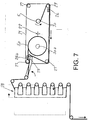
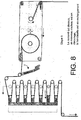
- FIGs 5 to 8 illustrate the different phases of the process of joining the support strips 4, 4a, 4b using simplified diagrams.
- the figure 5 shows the end of a spool 5.
- FIG. 6 shows the spool support 21 following its rotation of 180 ° in the opposite direction to the needles of a shows.
- the support strip 4 is guided by two of the return rollers 27.
- the front end of the new roll of reserve 5a is ready for the join operation.
- the organ of junction 29 came to press the two support strips 4, 4a, 4b to be joined against the support 26a to glue them to each other.
- the support strips 4, 4a, 4b are momentarily immobilized. It is then that the strip material accumulated in the reserve device 28 becomes empty to allow the transverse feed rollers 8 to feed without interrupting the rotary press in support strips 4, 4a, 4b of the material to be report on the substrate in strip 1.
- Cutting means (not shown), which can be associated at the junction member 29 then cut the rest of the carrier tape of the reel 5 empty and the connecting member 29 returns to its inactive position as illustrated in Figure 8, so that the new feed reel that was until then the reserve coil 5a begins to feed the rotary press.
- the reserve device 28 fills up again for the next reel change. In the meantime, there will be a need to replace the coil 5 empty by a new reserve coil 5a full.
- Downstream of the workstation 2, 3 is another device 15a, which is associated with an output traction group 50, equipped with pressers 50a, which are adjusted laterally to be positioned on bands 4, 4a, 4b, etc ....
- these bands can come from several stages (6, 6a, 6b of Figure 1) and therefore have average speeds different.
- the group 50, 50a rotates at a constant speed, more precisely at the speed of the fastest group of traction groups 8.
- the associated pressers 50a are lifted periodically. By doing so, they block the associated band 4.
- the bands 4 which we want to reduce the flow therefore make a movement of the stop / walk type.
- Activation / 50a pressers can be deactivated directly by the control of loops in the accumulation device 15a, or else by calculating a cycle regular basis and by superimposing any corrections from the monitoring individual loops in the accumulation device 15a.
- Another planned solution is to install an additional group 50, 50a, which would then adopt a specific average speed.
- FIG. 9 represents an alternative embodiment of an organ of modulation of the tape speed by replacing elements 8, 15, and 10, 11 of Figure 4. Indeed, it may be desirable to have a second run, for example to create a compact stamping unit in the form of an insert.
- the goal is to create a speed modulation for at less a metallized strip 44.
- This passes a first roll 40, linked to a suitable motor with a vacuum power supply 41 and unmounted means but known to bring the vacuum to the periphery of the cylinder, selectively between the generators A and E while passing through B.
- the band 44 is driven to continuous speed vc by the roller 40, whose speed of rotation wc is constant and chosen according to the average consumption required.
- Band 44 passes through the generators A, a point between B and B ', a point between C and C', D, and leave the device with a speed vi.
- the roll 43 is constructed as the roll 40, the only difference being that for wi the rotational speed is modulated to obtain a strip economy as described in the text Referring to Figures 2, 4.
- the average flow rate induced by the intermittent rotation wi of the roll 42 is identical to the flow rate given by the roll 40. It is understood easily that the BC trajectory is true only at one point in the cycle.
- the separation points B and C junction walk on surfaces based Profile of wi. We take advantage of the extremely low mass of band 44 for create a trajectory and a modulation vel vel vi perfectly controlled through the cycles.
- the speed wc can be influenced by a control of trajectory between the rollers 40, 42. If the points B and C have tendency to descend, this can be intercepted by a means of photocell (not shown) which will slightly increase the speed wc. And the opposite can be obtained by analogous means placed above B, C. this way, the software is free to overlay position corrections to roller 42 for the installation of holograms for example. A special modulation can also be supported, this can be very useful for joining the band 44 out of the meshing of a snapshot 16, for example.
Landscapes
- Engineering & Computer Science (AREA)
- Mechanical Engineering (AREA)
- Controlling Rewinding, Feeding, Winding, Or Abnormalities Of Webs (AREA)
- Replacement Of Web Rolls (AREA)
- Advancing Webs (AREA)
- Registering, Tensioning, Guiding Webs, And Rollers Therefor (AREA)
- Making Paper Articles (AREA)
- Attitude Control For Articles On Conveyors (AREA)
Abstract
Description
Claims (18)
- Presse rotative pour rapporter des motifs sur un substrat en bande (1), comprenant des moyens (C) pour entraíner longitudinalement ce substrat en bande (1) à vitesse déterminée, des moyens d'alimentation (6, 6a, 6b) d'au moins une bande support (4, 4a, 4b) du matériau desdits motifs, des moyens de transfert (2, 3) desdits motifs, de ladite bande support (4, 4a, 4b) en des emplacements déterminés dudit substrat en bande (1), des moyens (9) pour entraíner ladite bande support (4, 4a, 4b) à travers lesdits moyens de transfert (2, 3) de façon intermittente à ladite vitesse déterminée du substrat en bande (1), caractérisée en ce que lesdits moyens d'alimentation (6, 6a, 6b) sont disposés latéralement à la direction d'entraínement longitudinale dudit substrat en bande (1), des moyens (7, 7a, 7b) étant disposés le long de la trajectoire de ladite bande support (4, 4a, 4b) pour changer sa direction, d'une direction d'alimentation transversale à la direction d'entraínement longitudinale dudit substrat en bande (1), à une direction de transfert desdits motifs, parallèle à la direction d'entraínement longitudinale de ce substrat en bande (1).
- Presse selon la revendication 1, dans laquelle lesdits moyens d'alimentation (6, 6a, 6b) sont associés à des moyens (8) pour entraíner ladite bande support (4, 4a, 4b) à vitesse constante, un dispositif d'accumulation (15) de ladite bande support (4, 4a, 4b) étant disposé entre lesdits moyens (8) pour entraíner ladite bande support (4, 4a, 4b) à vitesse constante et lesdits moyens (9) pour entraíner cette bande support (4, 4a, 4b) de façon intermittente.
- Presse selon la revendication 1, dans laquelle lesdits moyens d'alimentation (6, 6a, 6b) comportent plusieurs unités d'alimentation indépendantes superposées.
- Presse selon la revendication 2, dans laquelle lesdits moyens (9) pour entraíner ladite bande support (4, 4a, 4b) de façon intermittente comportent un rouleau d'entraínement (10) avec lequel ladite bande support (4, 4a, 4b) est mise en contact à la sortie desdits moyens d'accumulation (15), un rouleau à rotation libre (11), parallèle audit rouleau d'entraínement (10) et des moyens (12-14) pour appliquer sélectivement ce rouleau à rotation libre (11) contre le rouleau d'entraínement (10), de manière à ce que ladite bande support (4, 4a, 4b) soit pincée entre lesdits rouleaux (10, 11) et ainsi entraínée par friction.
- Presse selon l'une des revendications 1 et 3, dans laquelle lesdits moyens d'alimentation (6, 6a, 6b) comprennent un mécanisme d'entraínement à vitesse déterminée (8), un dispositif de jonction (21, 26, 26a, 29) pour joindre la fin d'une bande support (4, 4a, 4b) et le début d'une autre bande support et une réserve (28) d'une certaine longueur de ladite bande support (4, 4a, 4b) entre ledit dispositif de jonction (29) et ledit mécanisme d'entraínement à vitesse déterminée (8) pour permettre l'alimentation continue de ladite bande support (4, 4a, 4b) pendant ladite opération de jonction.
- Presse selon la revendication 5, dans laquelle le mécanisme d'entraínement (8) comporte une série de galets presseurs (8a), associés à une des bandes (4, 4a), où ledit presseur peut être soulevé par intermittence, permettant ainsi une légère variation de débit de bande (4) sur le rouleau (8), permettant par-là de contrôler la position moyenne d'une boucle de bande (4, 4a) dans la chambre d'accumulation (16), le tout étant géré en bouclage automatique par le logiciel de la machine.
- Presse selon la revendication 6, dans laquelle les rouleaux de renvoi en amont du mécanisme d'entraínement (8) sont subdivisés en plusieurs parties adjacentes, de sorte à déconnecter l'avance des bandes (4, 4a, 4b) entre elles.
- Presse selon la revendication 5, dans laquelle ledit dispositif de jonction (21, 26, 26a, 29) comporte un support (21) pour au moins une bobine d'alimentation (5) et une bobine de réserve (5a) pour chaque bobine d'alimentation (5) desdites bandes support (4, 4a, 4b), relié à un bâti (6, 6a, 6b) par un axe central de pivotement (22) et comprenant des moyens de pivotement (23, 23a) pour recevoir lesdites bobines (5) dans des positions parallèles et symétriques audit axe central de pivotement (22), des guides (27) et des appuis (29) pour lesdites bandes support (4, 4a, 4b), associés à chacune desdites bobines d'alimentation (5) d'une part et desdites bobines de réserve (5a) d'autre part, ces guides (27) et ces appuis (26, 26a) étant disposés symétriquement par rapport audit axe central (22), des moyens (25) pour entraíner ledit support de bobines (21) par pas de 180° et des moyens (29) pour appliquer une portion finale de la bande support (4, 4a, 4b) de ladite bobine de rechange (5a) contre une portion initiale de la bande support (4, 4a, 4b) de ladite bobine d'alimentation (5) contre l'un desdits appuis (29) pour effectuer la jonction desdites portions adjacentes.
- Presse selon la revendication 2, dans laquelle ledit dispositif d'accumulation (15) de ladite bande support (4, 4a, 4b) comporte une chambre d'accumulation (16) pour des portions de réserve de ladite bande support, présentant une entrée (17) pour ladite bande support venant desdits moyens d'alimentation (6, 6a, 6b) et une sortie (18) pour ladite bande support vers lesdits moyens (9) pour entraíner cette bande support (4, 4a, 4b) de façon intermittente, des moyens (19) pour créer une dépression étant reliés à ladite chambre d'accumulation (16) qui comporte des détecteurs (20, 20a) pour détecter deux positions limites d'accumulation de ladite bande support (4, 4a, 4b) à l'intérieur de ladite chambre d'accumulation.
- Presse selon la revendication 2, dans laquelle lesdits moyens (8) pour entraíner ladite bande support (4, 4a, 4b) à vitesse constante, associés auxdits moyens d'alimentation (6, 6a, 6b), sont disposés en aval desdits moyens (7, 7a, 7b) pour changer la direction de ladite bande support (4, 4a, 4b) pour que la portion de cette bande support passant à travers lesdits moyens (7, 7a, 7b) pour changer leur direction soient maintenus constamment sous tension.
- Presse selon l'une des revendications précédentes, dans laquelle lesdits moyens pour changer de direction (7, 7a, 7b) comportent un organe de guidage rectiligne, disposé sur une bissectrice de l'angle formé entre la direction d'alimentation de ladite bande support (4, 4a, 4b) et la direction d'entraínement longitudinale dudit substrat en bande (1), pour que après avoir fait tourner ladite bande support (4, 4a, 4b) de 180° autour de lui, la direction longitudinale de cette bande support forme un angle de 90° entre son brin situé en amont et celui situé en aval dudit organe de guidage rectiligne (7, 7a, 7b).
- Presse selon la revendication 1, dans laquelle les bandes (4, 4a, 4b) sortantes sont entraínées à travers un autre dispositif d'accumulation (15a) par un dispositif de traction (50, 50a), où la vitesse de ce dernier est réglée en fonction de la position moyenne des boucles dans le dispositif (15a).
- Presse selon la revendication 12, dans laquelle le groupe de traction (50, 50a) est dédoublé et à chaque groupe (8, 8a) est associé un groupe (50, 50a) ayant sensiblement la même vitesse de base.
- Presse selon la revendication 12, dans laquelle le logiciel de commande pour les presseurs (8a) et (50a) est le même, et où les dispositifs d'accumulation (15) et (15a) sont identiques.
- Presse selon la revendication 12, dans laquelle les presseurs (50a) sont levés et les bandes associées bloquées de façon cadencée et où cette cadence est dictée par un système de surveillance des boucles dans le dispositif d'accumulation (15a) comme décrit pour le dispositif d'accumulation (15).
- Presse selon la revendication 4, dans laquelle un profil de vitesse intermittent est obtenu par la combinaison de 2 rouleaux (40, 42), où (40) tourne avec une vitesse wc constante et (42) avec une vitesse wi intermittente.
- Presse selon la revendication 16, dans laquelle les bandes (44) sont maintenues sans friction sur les surfaces des rouleaux (40, 42) par vacuum (41, 43).
- Presse selon la revendication 16, où la vitesse wc est ajustée par des moyens de contrôle placés au-dessus et en dessous de la zone (BC) entre les rouleaux (40, 42).
Applications Claiming Priority (2)
| Application Number | Priority Date | Filing Date | Title |
|---|---|---|---|
| CH14202002 | 2002-08-19 | ||
| CH14202002 | 2002-08-19 |
Publications (3)
| Publication Number | Publication Date |
|---|---|
| EP1393903A2 true EP1393903A2 (fr) | 2004-03-03 |
| EP1393903A3 EP1393903A3 (fr) | 2005-03-02 |
| EP1393903B1 EP1393903B1 (fr) | 2011-05-11 |
Family
ID=31193666
Family Applications (1)
| Application Number | Title | Priority Date | Filing Date |
|---|---|---|---|
| EP03017465A Expired - Lifetime EP1393903B1 (fr) | 2002-08-19 | 2003-08-01 | Presse rotative pour rapporter des motifs sur un substrat en bande |
Country Status (11)
| Country | Link |
|---|---|
| US (1) | US6779442B2 (fr) |
| EP (1) | EP1393903B1 (fr) |
| JP (1) | JP3745753B2 (fr) |
| KR (1) | KR20040016803A (fr) |
| CN (1) | CN1485202A (fr) |
| AT (1) | ATE508869T1 (fr) |
| AU (1) | AU2003234752A1 (fr) |
| BR (1) | BR0303109A (fr) |
| CA (1) | CA2437424A1 (fr) |
| ES (1) | ES2366023T3 (fr) |
| TW (1) | TWI238802B (fr) |
Families Citing this family (12)
| Publication number | Priority date | Publication date | Assignee | Title |
|---|---|---|---|---|
| DE102005008940C5 (de) * | 2004-04-13 | 2017-01-12 | manroland sheetfed GmbH | Vorrichtung zum Prägefoliendruck |
| DE502005008481D1 (de) * | 2004-04-13 | 2009-12-24 | Manroland Ag | Unterlage für prägevorrichtung |
| DE102005011568A1 (de) * | 2004-04-13 | 2005-11-17 | Man Roland Druckmaschinen Ag | Produktionsverfahren für eine Prägeeinrichtung in einer Bogendruckmaschine |
| DE102004019412A1 (de) * | 2004-04-19 | 2005-11-03 | Man Roland Druckmaschinen Ag | Verfahren zum Drucken elektrischer und/oder elektronischer Strukturen und Folie zur Verwendung in einem solchen Verfahren |
| DE102005043940C5 (de) * | 2005-03-10 | 2014-08-07 | manroland sheetfed GmbH | Prägeeinrichtung mit Folienlogistik in einer Bogendruckmaschine |
| DE102005062498A1 (de) * | 2005-12-27 | 2007-07-05 | Man Roland Druckmaschinen Ag | Verfahren zum Kaltfolienprägen |
| WO2008109633A2 (fr) * | 2007-03-06 | 2008-09-12 | Itw Food Equipment Group Llc | Gril à charbon de bois avec distribution de chaleur améliorée |
| DE102007015378A1 (de) * | 2007-03-28 | 2008-10-02 | Heidelberger Druckmaschinen Ag | Übergabevorrichtung für Folienwechsel |
| EP2100735A1 (fr) * | 2008-01-21 | 2009-09-16 | Vinfoil B.V. | Dispositif d'alimentation de film à utiliser dans un processus d'impression vers une presse d'impression |
| ES2533503B1 (es) * | 2013-10-07 | 2016-02-26 | Comexi Group Industries, Sau | Método para realizar diferentes aplicaciones específicas mediante una unidad impresora común, unidad impresora para implementar dicho método y máquina de tratamiento de sustrato en banda incluyendo dicha unidad impresora |
| CN112875375B (zh) * | 2021-03-10 | 2025-01-28 | 高登利盛影印(苏州)有限公司 | 一种便于调节的输送机构 |
| US11273103B1 (en) * | 2021-06-22 | 2022-03-15 | Vmi Holland B.V. | Method, computer program product and dispensing device for dispensing discrete medicaments |
Family Cites Families (17)
| Publication number | Priority date | Publication date | Assignee | Title |
|---|---|---|---|---|
| GB318902A (en) * | 1928-03-12 | 1929-09-12 | Thomas Johancen | Improvements in means for connecting rolls of paper webbing in printing presses |
| US2981432A (en) * | 1958-04-17 | 1961-04-25 | Dennison Mfg Co | Indicia-applying apparatus |
| FR2280516A1 (fr) * | 1974-07-31 | 1976-02-27 | Sublistatic Holding Sa | Procede et installation pour realiser une bande de transfert grande laize |
| US4488925A (en) * | 1983-03-11 | 1984-12-18 | Minnesota Mining And Manufacturing Company | Servo motor controlled labeler |
| GB8331899D0 (en) * | 1983-11-30 | 1984-01-04 | Markem Syst Ltd | Label printing machines |
| US4706863A (en) * | 1985-06-24 | 1987-11-17 | Mitsubishi Jukogyo Kabushiki Kaisha | Intermittent feeding apparatus for a continuous sheet |
| AU650636B2 (en) * | 1990-02-05 | 1994-06-30 | Molins Plc | Image applying method and apparatus |
| EP0861152B1 (fr) * | 1995-10-23 | 1999-12-22 | Clopay Plastic Products Company, Inc. | Produit, dispositif et procede pour la production de stratifies en ruban a partir d'un film polymere et d'une bande de materiau non tisse |
| JP3519087B2 (ja) * | 1996-10-14 | 2004-04-12 | ケーニツヒ ウント バウエル アクチエンゲゼルシヤフト | 折り装置へウエブ紙を供給する装置 |
| DE19728207A1 (de) * | 1997-07-02 | 1999-01-07 | Wifag Maschf | Wendeturmanordnung |
| FR2775633B1 (fr) * | 1998-03-09 | 2000-04-14 | Breger Emballages Sa | Installation d'impression par transfert, notamment par dorure |
| EP0965446B1 (fr) * | 1998-06-16 | 2003-02-26 | Kba-Giori S.A. | Machine d'impression de sécurité des papiers-valeurs |
| ATE226520T1 (de) * | 1998-09-08 | 2002-11-15 | Kba Giori Sa | Sicherheitsdruckmaschine für wertpapiere |
| DE19908973A1 (de) * | 1999-03-02 | 2000-09-07 | Voith Sulzer Papiertech Patent | Verfahren zur Regelung des Reißlängenverhältnisses einer erzeugten Papierbahn und Papiermaschine |
| US6387201B1 (en) * | 1999-05-14 | 2002-05-14 | Best Cutting Die Company | Rotary hot foil stamping machine |
| US6694872B1 (en) * | 1999-06-18 | 2004-02-24 | Holographic Label Converting, Inc. | In-line microembossing, laminating, printing, and diecutting |
| JP2002120348A (ja) * | 2000-10-13 | 2002-04-23 | Komori Corp | 印刷機 |
-
2003
- 2003-08-01 EP EP03017465A patent/EP1393903B1/fr not_active Expired - Lifetime
- 2003-08-01 AT AT03017465T patent/ATE508869T1/de not_active IP Right Cessation
- 2003-08-01 ES ES03017465T patent/ES2366023T3/es not_active Expired - Lifetime
- 2003-08-12 AU AU2003234752A patent/AU2003234752A1/en not_active Abandoned
- 2003-08-14 TW TW092122334A patent/TWI238802B/zh not_active IP Right Cessation
- 2003-08-18 CA CA002437424A patent/CA2437424A1/fr not_active Abandoned
- 2003-08-19 JP JP2003295440A patent/JP3745753B2/ja not_active Expired - Fee Related
- 2003-08-19 CN CNA03153676XA patent/CN1485202A/zh active Pending
- 2003-08-19 BR BR0303109-8A patent/BR0303109A/pt not_active IP Right Cessation
- 2003-08-19 KR KR1020030057310A patent/KR20040016803A/ko not_active Ceased
- 2003-08-19 US US10/644,104 patent/US6779442B2/en not_active Expired - Fee Related
Also Published As
| Publication number | Publication date |
|---|---|
| ATE508869T1 (de) | 2011-05-15 |
| ES2366023T3 (es) | 2011-10-14 |
| KR20040016803A (ko) | 2004-02-25 |
| BR0303109A (pt) | 2004-08-24 |
| EP1393903B1 (fr) | 2011-05-11 |
| TW200403175A (en) | 2004-03-01 |
| CN1485202A (zh) | 2004-03-31 |
| JP2004083286A (ja) | 2004-03-18 |
| TWI238802B (en) | 2005-09-01 |
| US20040031405A1 (en) | 2004-02-19 |
| EP1393903A3 (fr) | 2005-03-02 |
| JP3745753B2 (ja) | 2006-02-15 |
| US6779442B2 (en) | 2004-08-24 |
| CA2437424A1 (fr) | 2004-02-19 |
| AU2003234752A1 (en) | 2004-03-11 |
Similar Documents
| Publication | Publication Date | Title |
|---|---|---|
| EP1393903B1 (fr) | Presse rotative pour rapporter des motifs sur un substrat en bande | |
| EP3003703B1 (fr) | Unite de transformation d'un support en bande continue et machine de production d'emballages ainsi equipee | |
| FR2562526A1 (fr) | Chargeur de signatures, feuilles et produits similaires pour alimentateurs pour machines de conditionnement, de machines pour la reliure et analogues | |
| FR2612879A1 (fr) | Appareil d'alimentation en un materiau sous forme de film | |
| EP0612679B1 (fr) | Dispositif de distribution de feuilles semi-rigides, notamment de carton, à partir d'un empilement | |
| EP2834177B1 (fr) | Dispositif d'entraînement pour bande à estamper, module dérouleur et machine d'estampage ainsi équipée | |
| EP0514340A1 (fr) | Procédé et dispositif de préparation d'ébauches d'emballages | |
| EP2616242B1 (fr) | Dispositif de guidage de bandes pour machine d'estampage | |
| FR2484979A1 (fr) | Procede et appareil d'assemblage de matiere en feuille, notamment pour alimenter en continu des imprimantes rapides | |
| FR2501113A1 (fr) | Rotative offset a feuilles | |
| WO2012150386A1 (fr) | Dispositif d'empilage de feuilles de papier ou similaire | |
| EP1379457B1 (fr) | Procede pour recharger une fardeleuse a l'aide d'un film plastique, et fardeleuse mettant en oeuvre le procede | |
| EP0394707A1 (fr) | Dispositif d'introduction sequentielle de plaques dans une machine de façonnage | |
| FR2627456A1 (fr) | Appareil de distribution multiple | |
| EP3810537B1 (fr) | Dispositif de deroulage de bande et machine d'estampage d'elements en forme de feuilles | |
| BE889349A (fr) | Procede et appareil d'assemblage de matiere en feuille, notamment pour alimenter en continu des imprimantes rapides | |
| EP2613943B1 (fr) | Procede d'introduction de bandes a estamper dans un systeme assurant leur defilement et dispositif de mise en oeuvre d'un tel procede | |
| EP1588968B1 (fr) | Module de support et d'entraînement d'une matière en bande bobinée pour une machine la travaillant | |
| FR2826606A1 (fr) | Procede de reunion de sachets, dispositif pour la mise en oeuvre du procede et chaine de sachets ainsi que chaine de sachets empiles | |
| FR2772000A1 (fr) | Procede et dispositif pour reunir en lots des paquets en file continue au moyen de troncons de bandes adhesives | |
| FR2754240A1 (fr) | Dispositif d'application de bandes de dechirement | |
| EP1051295B1 (fr) | Procede et machine de fabrication d'etiquettes ou analogues rendues adhesives et deposees sur un support bobine | |
| FR2895984A1 (fr) | Dispositif et procede de preparation d'un troncon de ruban adhesif de longueur souhaitee a partir d'une bobine | |
| BE620609A (fr) | ||
| FR2505735A1 (fr) | Dispositif d'impression sur sangle |
Legal Events
| Date | Code | Title | Description |
|---|---|---|---|
| PUAI | Public reference made under article 153(3) epc to a published international application that has entered the european phase |
Free format text: ORIGINAL CODE: 0009012 |
|
| 17P | Request for examination filed |
Effective date: 20030801 |
|
| AK | Designated contracting states |
Kind code of ref document: A2 Designated state(s): AT BE BG CH CY CZ DE DK EE ES FI FR GB GR HU IE IT LI LU MC NL PT RO SE SI SK TR |
|
| AX | Request for extension of the european patent |
Extension state: AL LT LV MK |
|
| PUAL | Search report despatched |
Free format text: ORIGINAL CODE: 0009013 |
|
| AK | Designated contracting states |
Kind code of ref document: A3 Designated state(s): AT BE BG CH CY CZ DE DK EE ES FI FR GB GR HU IE IT LI LU MC NL PT RO SE SI SK TR |
|
| AX | Request for extension of the european patent |
Extension state: AL LT LV MK |
|
| AKX | Designation fees paid |
Designated state(s): AT BE BG CH CY CZ DE DK EE ES FI FR GB GR HU IE IT LI LU MC NL PT RO SE SI SK TR |
|
| 17Q | First examination report despatched |
Effective date: 20071109 |
|
| GRAP | Despatch of communication of intention to grant a patent |
Free format text: ORIGINAL CODE: EPIDOSNIGR1 |
|
| GRAS | Grant fee paid |
Free format text: ORIGINAL CODE: EPIDOSNIGR3 |
|
| GRAA | (expected) grant |
Free format text: ORIGINAL CODE: 0009210 |
|
| AK | Designated contracting states |
Kind code of ref document: B1 Designated state(s): AT BE BG CH CY CZ DE DK EE ES FI FR GB GR HU IE IT LI LU MC NL PT RO SE SI SK TR |
|
| REG | Reference to a national code |
Ref country code: GB Ref legal event code: FG4D Free format text: NOT ENGLISH |
|
| REG | Reference to a national code |
Ref country code: CH Ref legal event code: EP |
|
| REG | Reference to a national code |
Ref country code: IE Ref legal event code: FG4D |
|
| REG | Reference to a national code |
Ref country code: DE Ref legal event code: R096 Ref document number: 60337050 Country of ref document: DE Effective date: 20110622 |
|
| REG | Reference to a national code |
Ref country code: NL Ref legal event code: T3 |
|
| REG | Reference to a national code |
Ref country code: ES Ref legal event code: FG2A Ref document number: 2366023 Country of ref document: ES Kind code of ref document: T3 Effective date: 20111014 |
|
| PG25 | Lapsed in a contracting state [announced via postgrant information from national office to epo] |
Ref country code: SE Free format text: LAPSE BECAUSE OF FAILURE TO SUBMIT A TRANSLATION OF THE DESCRIPTION OR TO PAY THE FEE WITHIN THE PRESCRIBED TIME-LIMIT Effective date: 20110511 Ref country code: PT Free format text: LAPSE BECAUSE OF FAILURE TO SUBMIT A TRANSLATION OF THE DESCRIPTION OR TO PAY THE FEE WITHIN THE PRESCRIBED TIME-LIMIT Effective date: 20110912 |
|
| PG25 | Lapsed in a contracting state [announced via postgrant information from national office to epo] |
Ref country code: GR Free format text: LAPSE BECAUSE OF FAILURE TO SUBMIT A TRANSLATION OF THE DESCRIPTION OR TO PAY THE FEE WITHIN THE PRESCRIBED TIME-LIMIT Effective date: 20110812 Ref country code: SI Free format text: LAPSE BECAUSE OF FAILURE TO SUBMIT A TRANSLATION OF THE DESCRIPTION OR TO PAY THE FEE WITHIN THE PRESCRIBED TIME-LIMIT Effective date: 20110511 Ref country code: AT Free format text: LAPSE BECAUSE OF FAILURE TO SUBMIT A TRANSLATION OF THE DESCRIPTION OR TO PAY THE FEE WITHIN THE PRESCRIBED TIME-LIMIT Effective date: 20110511 Ref country code: CY Free format text: LAPSE BECAUSE OF FAILURE TO SUBMIT A TRANSLATION OF THE DESCRIPTION OR TO PAY THE FEE WITHIN THE PRESCRIBED TIME-LIMIT Effective date: 20110511 Ref country code: FI Free format text: LAPSE BECAUSE OF FAILURE TO SUBMIT A TRANSLATION OF THE DESCRIPTION OR TO PAY THE FEE WITHIN THE PRESCRIBED TIME-LIMIT Effective date: 20110511 |
|
| REG | Reference to a national code |
Ref country code: IE Ref legal event code: FD4D |
|
| PG25 | Lapsed in a contracting state [announced via postgrant information from national office to epo] |
Ref country code: EE Free format text: LAPSE BECAUSE OF FAILURE TO SUBMIT A TRANSLATION OF THE DESCRIPTION OR TO PAY THE FEE WITHIN THE PRESCRIBED TIME-LIMIT Effective date: 20110511 Ref country code: CZ Free format text: LAPSE BECAUSE OF FAILURE TO SUBMIT A TRANSLATION OF THE DESCRIPTION OR TO PAY THE FEE WITHIN THE PRESCRIBED TIME-LIMIT Effective date: 20110511 Ref country code: IE Free format text: LAPSE BECAUSE OF FAILURE TO SUBMIT A TRANSLATION OF THE DESCRIPTION OR TO PAY THE FEE WITHIN THE PRESCRIBED TIME-LIMIT Effective date: 20110511 |
|
| BERE | Be: lapsed |
Owner name: BOBST S.A. Effective date: 20110831 |
|
| PG25 | Lapsed in a contracting state [announced via postgrant information from national office to epo] |
Ref country code: SK Free format text: LAPSE BECAUSE OF FAILURE TO SUBMIT A TRANSLATION OF THE DESCRIPTION OR TO PAY THE FEE WITHIN THE PRESCRIBED TIME-LIMIT Effective date: 20110511 Ref country code: RO Free format text: LAPSE BECAUSE OF FAILURE TO SUBMIT A TRANSLATION OF THE DESCRIPTION OR TO PAY THE FEE WITHIN THE PRESCRIBED TIME-LIMIT Effective date: 20110511 Ref country code: DK Free format text: LAPSE BECAUSE OF FAILURE TO SUBMIT A TRANSLATION OF THE DESCRIPTION OR TO PAY THE FEE WITHIN THE PRESCRIBED TIME-LIMIT Effective date: 20110511 |
|
| PLBE | No opposition filed within time limit |
Free format text: ORIGINAL CODE: 0009261 |
|
| STAA | Information on the status of an ep patent application or granted ep patent |
Free format text: STATUS: NO OPPOSITION FILED WITHIN TIME LIMIT |
|
| PG25 | Lapsed in a contracting state [announced via postgrant information from national office to epo] |
Ref country code: MC Free format text: LAPSE BECAUSE OF NON-PAYMENT OF DUE FEES Effective date: 20110831 |
|
| 26N | No opposition filed |
Effective date: 20120214 |
|
| GBPC | Gb: european patent ceased through non-payment of renewal fee |
Effective date: 20110811 |
|
| PG25 | Lapsed in a contracting state [announced via postgrant information from national office to epo] |
Ref country code: BE Free format text: LAPSE BECAUSE OF NON-PAYMENT OF DUE FEES Effective date: 20110831 |
|
| REG | Reference to a national code |
Ref country code: DE Ref legal event code: R097 Ref document number: 60337050 Country of ref document: DE Effective date: 20120214 |
|
| PG25 | Lapsed in a contracting state [announced via postgrant information from national office to epo] |
Ref country code: GB Free format text: LAPSE BECAUSE OF NON-PAYMENT OF DUE FEES Effective date: 20110811 |
|
| PG25 | Lapsed in a contracting state [announced via postgrant information from national office to epo] |
Ref country code: LU Free format text: LAPSE BECAUSE OF NON-PAYMENT OF DUE FEES Effective date: 20110801 |
|
| PG25 | Lapsed in a contracting state [announced via postgrant information from national office to epo] |
Ref country code: BG Free format text: LAPSE BECAUSE OF FAILURE TO SUBMIT A TRANSLATION OF THE DESCRIPTION OR TO PAY THE FEE WITHIN THE PRESCRIBED TIME-LIMIT Effective date: 20110811 |
|
| PG25 | Lapsed in a contracting state [announced via postgrant information from national office to epo] |
Ref country code: TR Free format text: LAPSE BECAUSE OF FAILURE TO SUBMIT A TRANSLATION OF THE DESCRIPTION OR TO PAY THE FEE WITHIN THE PRESCRIBED TIME-LIMIT Effective date: 20110511 |
|
| PG25 | Lapsed in a contracting state [announced via postgrant information from national office to epo] |
Ref country code: HU Free format text: LAPSE BECAUSE OF FAILURE TO SUBMIT A TRANSLATION OF THE DESCRIPTION OR TO PAY THE FEE WITHIN THE PRESCRIBED TIME-LIMIT Effective date: 20110511 |
|
| REG | Reference to a national code |
Ref country code: FR Ref legal event code: PLFP Year of fee payment: 14 |
|
| REG | Reference to a national code |
Ref country code: FR Ref legal event code: PLFP Year of fee payment: 15 |
|
| REG | Reference to a national code |
Ref country code: FR Ref legal event code: PLFP Year of fee payment: 16 |
|
| PGFP | Annual fee paid to national office [announced via postgrant information from national office to epo] |
Ref country code: NL Payment date: 20200715 Year of fee payment: 18 |
|
| PGFP | Annual fee paid to national office [announced via postgrant information from national office to epo] |
Ref country code: FR Payment date: 20200811 Year of fee payment: 18 Ref country code: ES Payment date: 20200901 Year of fee payment: 18 Ref country code: DE Payment date: 20200722 Year of fee payment: 18 |
|
| PGFP | Annual fee paid to national office [announced via postgrant information from national office to epo] |
Ref country code: CH Payment date: 20200811 Year of fee payment: 18 Ref country code: IT Payment date: 20200713 Year of fee payment: 18 |
|
| REG | Reference to a national code |
Ref country code: DE Ref legal event code: R119 Ref document number: 60337050 Country of ref document: DE |
|
| REG | Reference to a national code |
Ref country code: CH Ref legal event code: PL |
|
| REG | Reference to a national code |
Ref country code: NL Ref legal event code: MM Effective date: 20210901 |
|
| PG25 | Lapsed in a contracting state [announced via postgrant information from national office to epo] |
Ref country code: LI Free format text: LAPSE BECAUSE OF NON-PAYMENT OF DUE FEES Effective date: 20210831 Ref country code: CH Free format text: LAPSE BECAUSE OF NON-PAYMENT OF DUE FEES Effective date: 20210831 |
|
| PG25 | Lapsed in a contracting state [announced via postgrant information from national office to epo] |
Ref country code: NL Free format text: LAPSE BECAUSE OF NON-PAYMENT OF DUE FEES Effective date: 20210901 |
|
| PG25 | Lapsed in a contracting state [announced via postgrant information from national office to epo] |
Ref country code: IT Free format text: LAPSE BECAUSE OF NON-PAYMENT OF DUE FEES Effective date: 20210801 Ref country code: FR Free format text: LAPSE BECAUSE OF NON-PAYMENT OF DUE FEES Effective date: 20210831 Ref country code: DE Free format text: LAPSE BECAUSE OF NON-PAYMENT OF DUE FEES Effective date: 20220301 |
|
| REG | Reference to a national code |
Ref country code: ES Ref legal event code: FD2A Effective date: 20220926 |
|
| PG25 | Lapsed in a contracting state [announced via postgrant information from national office to epo] |
Ref country code: ES Free format text: LAPSE BECAUSE OF NON-PAYMENT OF DUE FEES Effective date: 20210802 |