EP1393126B1 - Rastmechanismus - Google Patents
Rastmechanismus Download PDFInfo
- Publication number
- EP1393126B1 EP1393126B1 EP02732667A EP02732667A EP1393126B1 EP 1393126 B1 EP1393126 B1 EP 1393126B1 EP 02732667 A EP02732667 A EP 02732667A EP 02732667 A EP02732667 A EP 02732667A EP 1393126 B1 EP1393126 B1 EP 1393126B1
- Authority
- EP
- European Patent Office
- Prior art keywords
- latching
- mechanism according
- projections
- latching mechanism
- ring element
- Prior art date
- Legal status (The legal status is an assumption and is not a legal conclusion. Google has not performed a legal analysis and makes no representation as to the accuracy of the status listed.)
- Expired - Lifetime
Links
- 230000003287 optical effect Effects 0.000 claims description 20
- 230000008878 coupling Effects 0.000 claims 2
- 238000010168 coupling process Methods 0.000 claims 2
- 238000005859 coupling reaction Methods 0.000 claims 2
- 150000001875 compounds Chemical class 0.000 description 4
- 239000007787 solid Substances 0.000 description 4
- 230000009286 beneficial effect Effects 0.000 description 1
- 238000010276 construction Methods 0.000 description 1
- 229910003460 diamond Inorganic materials 0.000 description 1
- 239000010432 diamond Substances 0.000 description 1
- 239000000428 dust Substances 0.000 description 1
- 230000000694 effects Effects 0.000 description 1
- 238000003780 insertion Methods 0.000 description 1
- 230000037431 insertion Effects 0.000 description 1
- 238000004519 manufacturing process Methods 0.000 description 1
- 239000002245 particle Substances 0.000 description 1
Images


Classifications
-
- G—PHYSICS
- G02—OPTICS
- G02B—OPTICAL ELEMENTS, SYSTEMS OR APPARATUS
- G02B7/00—Mountings, adjusting means, or light-tight connections, for optical elements
- G02B7/02—Mountings, adjusting means, or light-tight connections, for optical elements for lenses
- G02B7/14—Mountings, adjusting means, or light-tight connections, for optical elements for lenses adapted to interchange lenses
-
- G—PHYSICS
- G03—PHOTOGRAPHY; CINEMATOGRAPHY; ANALOGOUS TECHNIQUES USING WAVES OTHER THAN OPTICAL WAVES; ELECTROGRAPHY; HOLOGRAPHY
- G03B—APPARATUS OR ARRANGEMENTS FOR TAKING PHOTOGRAPHS OR FOR PROJECTING OR VIEWING THEM; APPARATUS OR ARRANGEMENTS EMPLOYING ANALOGOUS TECHNIQUES USING WAVES OTHER THAN OPTICAL WAVES; ACCESSORIES THEREFOR
- G03B17/00—Details of cameras or camera bodies; Accessories therefor
- G03B17/02—Bodies
- G03B17/12—Bodies with means for supporting objectives, supplementary lenses, filters, masks, or turrets
- G03B17/14—Bodies with means for supporting objectives, supplementary lenses, filters, masks, or turrets interchangeably
Definitions
- the invention relates to a latching mechanism according to the preamble of Claim 1.
- From US 4,600,277 is a telescope with a main body and with at least two interchangeable insight systems known
- the two insight systems differ Significantly characterized by the fact that a first insight system one to the optical axis of Telescopic coaxial arrangement or alignment has.
- a second insight system has an angular design and allows an insight into the telescope below a 45 ° angle to the optical axis through the lens housed in the main body
- the viewing arrangements are with the main housing or telescope connectable by means of a bayonet lock.
- the bayonet lock includes on the Insight system L-shaped protrusions. These protrusions are connected to the housing of the respective viewing system firmly connected and have an axial orientation with respect on the optical axis.
- projections are associated with recesses in a fixed to the main housing plate, which is perpendicular to the optical axis of the telescope is arranged. Compared to each other, the projections and the recesses have different extensions in the circumferential direction, so that at Connection of viewing system and main housing the viewing system to the main body can only assume a predetermined and thus defined position.
- a disadvantage of these systems is that the projections formed on a component when snapping into the other component, such as main body or camera body, strong be charged. This heavy load is due to frequent connection and Loosen to damage the protrusions.
- the object of the invention is to develop a releasable connection such that the Load is reduced at the provided for the preparation of the compound projections
- a locking mechanism with a rotatably mounted To provide ring member having recesses for receiving the projections, wherein the releasable connection is provided by means of the ring member, the on the projections acting load can be reduced because the projections at Ausfubrung the rotational movement of the recesses are received.
- the projections force-free or almost free of force in the in the Ring element formed recesses are introduced.
- the ring element at least one spring element associate with which it cooperates, being in the preparation of the solid compound the housing parts clamping energy of this Federlementes is free.
- latching projections to arrange the associated recesses perpendicular to the projections.
- the ring element in relaxation of or the spring elements performs a movement in the axial direction, wherein the axial direction is determined by the optical axis.
- the ring element performs a tilting movement for producing a latching. This can occur in particular if only one spring element is provided
- This locking mechanism has been especially for connecting optical Components, especially an eyepiece and an optical device as special suitable exposed.
- this locking mechanism particularly suitable, by means of which a change of the eyepieces is easy to carry out and that works reliably. In particular, it does not require a separate lever when releasing the locking mechanism to operate, which has a negative effect on the Händling would change the eyepieces.
- this locking mechanism can alone by moving the housing parts against each other, the connection of the housing parts, especially eyepiece and main body, to be solved.
- the telescope 1 comprises a lens 5, an eyepiece 3 and two housing parts 7, 9.
- the lens 5 is fixedly connected to the housing part 7 and the Eyepiece 3 is detachably connected to the housing part 9.
- the housing parts 7 and 9 are in turn firmly connected with each other.
- the telescope 1 has a grip area 13, in which recessed grips 15 are formed on both longitudinal sides.
- To connect with a tripod mount 11 is provided on a tripod.
- the telescope is by means of a Fine drive 19 and a coarse drive 17 focusable.
- the housing 4 of the eyepiece 3 is Coaxially arranged to an optical axis through which arranged in the eyepiece 3 optical lenses, not shown, is fixed.
- the eyepiece 3 On the with the housing part 9 to connecting side, the eyepiece 3 has an extension 23. End is the extension with Projections 25 provided.
- These projections 25 have different shape design, here different extent in the circumferential direction. But it could be one too different extent of the projections in the radial direction or only one different shape of the projections, such as diamond shape, ring segment, etc. provided be.
- a receptacle 35 is arranged in the housing part 9 of the telescope 1.
- the receptacle comprises a cover 73, a ring element 57 and a sleeve 29.
- the lid 73 is provided with a closure plate 75, which is transparent and through which an inner Volume of the telescope 1 is sealed to the environment.
- a closure plate 75 which is transparent and through which an inner Volume of the telescope 1 is sealed to the environment.
- cover 73 with end plate 75 ensures that no moisture in the penetrates through the housing parts 7, 9 and the lens formed volume. Also is this inner volume thus protected from dirt particles, especially dust.
- the ring member 57 is rotatably mounted.
- Rotation limit 63 provided for that of the ring member 57.
- This sleeve 29 is fixedly connected to the lid 73, wherein between the the latter arranged ring element 57 between the sleeve 29 and the cover 73 in limited extent in the axial direction can be moved.
- the ramp 60 can also be formed on the locking grooves 51.
- the spring elements 67 and leaf springs 69 is biased simultaneously.
- the spring elements 67 and leaf springs 69 are preferably both each with a ramp 60th formed on the cooperating when releasing the connection surfaces are provided. If the spring elements 67 are prestressed, then the latching projections 59 stand with formed on the sleeve 29 contact areas 55 in conjunction or support this off. These contact areas 55 are formed by axial projections 53, the are formed integrally with the sleeve 29. These contact areas are in Circumferentially arranged adjacent to the locking grooves 51.
- leaf springs 69 simultaneously locking projections (not shown), so the provided leaf springs could be arranged instead of the latching projections, the ring element sliding on the opposite side with the lid in Contact would be.
- latching projections and locking grooves could also be arranged on the lid side, in which case the ring element slidably with the sleeve in would connect.
- the sleeve 29 is on the ring member 57 facing side with main springs 41st Mistake.
- the spring force of the main springs acts in the axial direction.
- main springs 41 are in this embodiment leaf springs 43, which by fastening elements 45, here screws 47, with the sleeve 29 are firmly connected.
- Recesses 49 for providing a possible spring travel of the main springs 41st formed on the outer circumference is the sleeve 29 with a radial profile 31.
- This Radial profile 31 includes two annular projections. This profile is for Preparation of the fixed connection of cover 73 and sleeve 29th
- a connecting ring 33 is provided, through the one along with a formed in the eyepiece 3 circumferential groove Stop 27 is formed.
- the eyepiece 3 has on the side facing the sleeve 29 on an extension 23 which is aligned coaxially with the optical axis20. Is the eyepiece 3 fixedly connected to the telescope 1, the sleeve 29 and the ring member 57 is arranged coaxially to the extension 23. The bearing of this extension 23 within the sleeve 29, wherein the ring member 57 is rotatably mounted on the extension, is shown in FIG shown.
- the projections 25 are at the end, on which the sleeve 29 facing side formed on the extension 23.
- the spring element is to be arranged such that the spring force of the spring elements also acts in the radial direction, so that when latching the clamping energy of the spring elements becomes free.
Landscapes
- Physics & Mathematics (AREA)
- General Physics & Mathematics (AREA)
- Optics & Photonics (AREA)
- Telescopes (AREA)
- Medicines Containing Antibodies Or Antigens For Use As Internal Diagnostic Agents (AREA)
- Superconductors And Manufacturing Methods Therefor (AREA)
- Chair Legs, Seat Parts, And Backrests (AREA)
- Hooks, Suction Cups, And Attachment By Adhesive Means (AREA)
- Snaps, Bayonet Connections, Set Pins, And Snap Rings (AREA)
Description
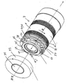
- Figur 1:
- Teleskop;
- Figur 2:
- Rastmechanismus; und
- Figur 3:
- Vergrößerte Darstellung der Aufnahme des Rastmechanismuses
- Figur 4:
- Darstellung vom im Ringelement aufgenommenen Vorsprüngen.
Die Vorsprünge 25 sind endseitig, auf der der Muffe 29 zugewandten Seite an dem Fortsatzes 23 ausgebildet.
- 1
- Teleskop
- 3
- Okular
- 4
- Gehäuse
- 5
- Objektiv
- 7
- Gehäuseteil
- 9
- Gehäuseteil
- 11
- Stativ
- 13
- Griffbereich
- 15
- Griffmulden
- 17
- Grobtrieb
- 19
- Feintrieb
- 20
- optische Achse
- 21
- Rastmechanismus
- 23
- Fortsatz
- 25
- Vorsprünge
- 27
- Anschlag
- 29
- Muffe
- 31
- Radialprofil
- 33
- Anschlußring
- 35
- Aufnahme
- 37
- Ausnehmung
- 39
- Anschlag
- 41
- Hauptfedern
- 43
- Blattfedern
- 45
- Befestigungselemement
- 47
- Schrauben
- 49
- Vertiefungen
- 51
- Rastnuten
- 53
- Axialvorsprung
- 55
- Kontaktbereich
- 57
- Ringelement
- 58
- Ausnehmung
- 59
- Rastvorsprünge
- 60
- Rampe
- 61
- Tangentialausnehmung
- 62
- Stäbe
- 63
- Drehbegrenzung
- 65
- Führungsschlitz
- 67
- Federelement
- 69
- Blattfeder
- 71
- Schrauben
- 73
- Deckel
- 75
- Abschlußplatte
Claims (17)
- Rastmechanismus zum Herstellen einer lösbaren Verbindung eines Gehäuseteils mit einem weiteren Gehäuseteil, wobei an einem der Gehäuseteile Vorsprünge (25) vorgesehen sind und wobei bei der Herstellung der lösbaren Verbindung mittels einer Drehbewegung der Gehäuseteile gegeneinander Rastvorsprünge (59) in zugeordnete Rastausnehmungen (51) verrastend eingreifen, dadurch gekennzeichnet, daß der Rastmechanismus (21) ein drehbar gelagertes Ringelement (57) umfaßt, das zwischen einem Deckel (73) und einer Muffe (29) angeordnet ist, wobei Deckel (73) und Muffe (29) ortsfest zu einem der Gehäuseteile (9) angeordnet sind und das Ausnehmungen (58) zur Aufnahme der Vorsprünge (25) umfaßt und das mittels Rastausnehmungen (51) und Rastvorsprüngen (59) bezüglich Drehung fixierbar ist.
- Rastmechanismus nach Anspruch 1, dadurch gekennzeichnet, daß mit dem Ringelement (51) mindestens ein Federelement (67) zusammen wirkt, wobei bei Herstellung der lösbaren Verbindung der Gehäuseteile (4, 9) Spannenergie des mindestens einen Federelementes (67) frei wird.
- Rastmechanismus nach Anspruch 1, dadurch gekennzeichnet, daß der vorgesehene Rastvorsprung (59) und die zugeordnete Rastausnehmung (51) mit senkrechter Ausrichtung in bezug auf die Ausrichtung der Vorsprünge (25) angeordnet sind.
- Rastmechanismus nach Anspruch 2 oder Anspruch 3, dadurch gekennzeichnet, daß bei Entspannung des Federelementes (67) das Ringelement (57) eine Bewegung in axialer Richtung entlang einer Drehachse (20) des Ringelements (57) ausführt.
- Rastmechanismus nach Anspruch 2 oder Anspruch 3, dadurch gekennzeichnet, daß durch das Federelement (67) ein Rastvorsprung (59) gebildet wird.
- Rastmechanismus nach mindestens einem der Ansprüche 1 - 3, dadurch gekennzeichnet, daß die Federkraft des einen Federelementes in radialer Richtung wirkt und die Rastnut oder der Rastvorsprung am Umfang des Ringelementes (57) mit radialer Ausrichtung angeordnet ist.
- Rastmechanismus nach mindestens einem der vorangegangenen Ansprüche, dadurch gekennzeichnet, daß mehrere in paralleler Richtung wirkende Federelemente (67) vorgesehen sind.
- Rastmechanismus nach mindestens einem der vorangegangenen Ansprüche, dadurch gekennzeichnet, daß mehrere Rastvorsprünge (59) mit zugeordneten Rastnuten (51) vorgesehen sind.
- Rastmechanismus nach einem der Ansprüche 1 bis 8, dadurch gekennzeichnet, daß jeweils zwei Federelemente diametral gegenüberliegend angeordnet sind, so daß bei Verrastung das Ringelement (57) die koaxiale Anordnung zur optischen Achse (20) beibehält.
- Rastmechanismus nach mindestens einem der vorangegangenen Ansprüche, dadurch gekennzeichnet, daß zur Kompensation eines axialen Spiels der Gehäuseteile (4, 9) gegeneinander Hauptfedern (41) vorgesehen sind.
- Rastmechanismus nach Anspruch 10, dadurch gekennzeichnet, daß die Hauptfedern (41) nur bei verbundenen Gehäuseteilen (4, 9) unter Spannung stehen.
- Rastmechanismus nach mindestens einem der vorangegangenen Ansprüche, dadurch gekennzeichnet, daß die Hauptfedern (41) zum Ausgleichen des axialen Spiels mit den Vorsprüngen (25) in Wirkverbindung treten.
- Rastmechanismus nach Anspruch 12, dadurch gekennzeichnet, daß das Ringelement (57) durch Anschläge um ein vorbestimmtes Winkelmaß drehbar ist.
- Rastmechanismus nach Anspruch 2 oder Anspruch 12, dadurch gekennzeichnet, daß die Rastnut (51) oder der Rastvorsprung (59) in Drehrichtung des Ringelementes (57) zum Lösen der Rastverbindung eine Rampe (60) aufweist.
- Rastmechanismus nach Anspruch 14, dadurch gekennzeichnet, daß die Steigung der Rampe derart gewählt ist, daß das zum Lösen der Verbindung erforderliche Moment größer ist, als das Moment was zum Herstellen der Verbindung der beiden Gehäuseteile (4, 9) erforderlich ist.
- Okular, für ein optisches Gerät, insbesondere Fernrohr, dadurch gekennzeichnet, daß das Okular ein Gehäuseteil (4) umfaßt, das mittels eines Rastmechanismuses nach mindestens einem der Ansprüche 1 bis 15 mit dem optischen Gerät (1) verbindbar ist.
- Teleskop mit einem auswechselbaren Okular, dadurch gekennzeichnet, daß zur Herstellung einer lösbaren Verbindung des Okulars (3) mit dem Teleskop (1) ein Rastmechanismus (21) nach einem der Ansprüche 1-15 vorgesehen ist.
Applications Claiming Priority (3)
| Application Number | Priority Date | Filing Date | Title |
|---|---|---|---|
| DE10121439 | 2001-04-27 | ||
| DE10121439A DE10121439A1 (de) | 2001-04-27 | 2001-04-27 | Rastmechanismus |
| PCT/EP2002/004569 WO2002088840A1 (de) | 2001-04-27 | 2002-04-25 | Rastmechanismus |
Publications (2)
| Publication Number | Publication Date |
|---|---|
| EP1393126A1 EP1393126A1 (de) | 2004-03-03 |
| EP1393126B1 true EP1393126B1 (de) | 2005-12-14 |
Family
ID=7683447
Family Applications (1)
| Application Number | Title | Priority Date | Filing Date |
|---|---|---|---|
| EP02732667A Expired - Lifetime EP1393126B1 (de) | 2001-04-27 | 2002-04-25 | Rastmechanismus |
Country Status (5)
| Country | Link |
|---|---|
| US (1) | US6967794B2 (de) |
| EP (1) | EP1393126B1 (de) |
| AT (1) | ATE313104T1 (de) |
| DE (2) | DE10121439A1 (de) |
| WO (1) | WO2002088840A1 (de) |
Families Citing this family (17)
| Publication number | Priority date | Publication date | Assignee | Title |
|---|---|---|---|---|
| DE10218171A1 (de) * | 2001-04-27 | 2002-10-31 | Hensoldt & Soehne Optik | Grob- und Feintrieb für ein Monokular, insbesondere für ein Fernrohr |
| JP4647022B2 (ja) * | 2008-09-09 | 2011-03-09 | パナソニック株式会社 | レンズフード着脱機構 |
| US8134116B2 (en) | 2009-01-12 | 2012-03-13 | Cognex Corporation | Modular focus system for image based code readers |
| KR101621895B1 (ko) * | 2009-12-28 | 2016-05-17 | 엘지이노텍 주식회사 | 구조안정 카메라 모듈 |
| AT510937B1 (de) * | 2010-12-23 | 2021-02-15 | Swarovski Optik Kg | Modulares teleskop |
| AT510936B1 (de) | 2010-12-23 | 2021-02-15 | Swarovski Optik Kg | Teleskop mit miteinander verbindbaren modulen |
| AT510935B1 (de) * | 2010-12-23 | 2021-02-15 | Swarovski Optik Kg | Teleskop mit objektiv und okularmodul |
| JP5722134B2 (ja) * | 2011-06-23 | 2015-05-20 | オリンパスイメージング株式会社 | 光学機器 |
| US10498933B2 (en) | 2011-11-22 | 2019-12-03 | Cognex Corporation | Camera system with exchangeable illumination assembly |
| US11366284B2 (en) | 2011-11-22 | 2022-06-21 | Cognex Corporation | Vision system camera with mount for multiple lens types and lens module for the same |
| US8731389B2 (en) | 2011-11-22 | 2014-05-20 | Cognex Corporation | Auto-focus mechanism for vision system camera |
| US8947590B2 (en) | 2011-11-22 | 2015-02-03 | Cognex Corporation | Vision system camera with mount for multiple lens types |
| WO2016065518A1 (zh) * | 2014-10-27 | 2016-05-06 | 深圳市大疆创新科技有限公司 | 镜头限位组件、相机的机身及相机模块 |
| JP6581732B2 (ja) * | 2016-09-16 | 2019-09-25 | 富士フイルム株式会社 | レンズユニット、カメラシステム及びレンズマウント |
| US10877296B2 (en) * | 2017-03-28 | 2020-12-29 | Kerr Corporation | Rotational alignment of interchangeable loupes |
| DE102021108266B4 (de) | 2020-09-16 | 2025-01-30 | Reimund Walter | Adaptervorrichtung zur Befestigung eines Zusatzgerätes sowie Befestigungsringe einer Adaptervorrichtung |
| CN214846194U (zh) * | 2020-11-17 | 2021-11-23 | 中强光电股份有限公司 | 转接组件及投影装置 |
Family Cites Families (7)
| Publication number | Priority date | Publication date | Assignee | Title |
|---|---|---|---|---|
| US3620149A (en) * | 1969-08-04 | 1971-11-16 | Olygin Optical Corp | Threaded type coupling device for coupling a lens barrel with a camera body |
| US4302077A (en) * | 1978-09-29 | 1981-11-24 | Canon Kabushiki Kaisha | Bayonet device for lens barrel |
| DE7901401U1 (de) * | 1979-01-19 | 1980-07-03 | Ernst Leitz Wetzlar Gmbh, 6330 Wetzlar | Mikroskopobjektivfassung |
| US4600277A (en) * | 1984-02-13 | 1986-07-15 | Murray Jr Joseph E | Telescope with multiple image-viewing assemblies |
| US5249082A (en) * | 1991-05-08 | 1993-09-28 | Eastman Kodak Company | Exact constraint arrangement for and methods of mounting an element such as a lens |
| US5464300A (en) * | 1993-04-29 | 1995-11-07 | Crainich; Lawrence | Medical instrument and coupling apparatus for same |
| JPH08122884A (ja) * | 1994-10-20 | 1996-05-17 | Fuji Photo Optical Co Ltd | テレビカメラ用マウント装置 |
-
2001
- 2001-04-27 DE DE10121439A patent/DE10121439A1/de not_active Withdrawn
-
2002
- 2002-04-25 AT AT02732667T patent/ATE313104T1/de not_active IP Right Cessation
- 2002-04-25 WO PCT/EP2002/004569 patent/WO2002088840A1/de not_active Ceased
- 2002-04-25 DE DE50205289T patent/DE50205289D1/de not_active Expired - Fee Related
- 2002-04-25 EP EP02732667A patent/EP1393126B1/de not_active Expired - Lifetime
-
2003
- 2003-10-27 US US10/695,557 patent/US6967794B2/en not_active Expired - Fee Related
Also Published As
| Publication number | Publication date |
|---|---|
| US20040141232A1 (en) | 2004-07-22 |
| DE50205289D1 (de) | 2006-01-19 |
| DE10121439A1 (de) | 2002-10-31 |
| WO2002088840A1 (de) | 2002-11-07 |
| ATE313104T1 (de) | 2005-12-15 |
| EP1393126A1 (de) | 2004-03-03 |
| US6967794B2 (en) | 2005-11-22 |
Similar Documents
| Publication | Publication Date | Title |
|---|---|---|
| DE10121439A1 (de) | Rastmechanismus | |
| DE102010060343B4 (de) | Selbstarretierende Einstellvorrichtung | |
| DE69120642T2 (de) | Endoskopischer Adapter mit Zwischenschicht | |
| DE102011051677B4 (de) | Mikroskopobjektiv und Mikroskop | |
| DE69216763T2 (de) | Feldstecher mit Einzelfokussierung | |
| WO2009118070A1 (de) | Elektrowerkzeugmaschine | |
| EP2708792A2 (de) | Stativkopf | |
| DE4244161A1 (en) | Automatic focus field glasses - have lens which can be moved in direction of optical axis for sharp adjustment and lenses movable along optical axis for varying refractory force | |
| WO2008135006A1 (de) | Binokulares fernrohr | |
| DE102016100219A1 (de) | Verstellvorrichtung für die Einstellung eines Zielfernrohrs und hiermit ausgestattetes Zielfernrohr | |
| DE102010017707A1 (de) | Manueller Fokussiermechanismus eines Abbildungsgeräts und Abbildungsgerät | |
| DE2038767B2 (de) | Schraubkupplung zum Befestigen eines Objektivs an einer Kamera | |
| DE4035550A1 (de) | Objektivabdeckung | |
| DE102014206657B4 (de) | Vorrichtung zum Einstellen eines Kameraobjektivs | |
| DE19713276C2 (de) | Vorrichtung zum Positionieren von Bauelementen innerhalb endoskopischer Systeme | |
| EP0307440B1 (de) | Objektivfassung für ein varioobjektiv für fernsehkameras | |
| EP3538952A1 (de) | Adapter zum verschwenken eines objektivs | |
| EP0027494B1 (de) | Wechselobjektiv für photographische Kameras, insbesondere Spiegelreflexkameras | |
| EP1775613A1 (de) | Vorrichtung zur Befestigung von Bildaufnahmegeräten an einem Beobachtungsfernrohr | |
| DE712349C (de) | Fotografische Kamera mit Auswechselobjektiven | |
| DE10320964A1 (de) | Einstellvorrichtung für eine optische Einheit | |
| DE112019002911T5 (de) | Binokulares Fernglas mit einer eingebauten Strichplatte | |
| EP1533645B1 (de) | Kupplung für ein Endoskop | |
| DE10209283A1 (de) | Vorrichtung zum Umschalten eines schwenkbaren Halters | |
| DE3783906T2 (de) | Geraet zur kinematischen verbindung in einer kamera mit einem wechselobjektiv. |
Legal Events
| Date | Code | Title | Description |
|---|---|---|---|
| PUAI | Public reference made under article 153(3) epc to a published international application that has entered the european phase |
Free format text: ORIGINAL CODE: 0009012 |
|
| 17P | Request for examination filed |
Effective date: 20030925 |
|
| AK | Designated contracting states |
Kind code of ref document: A1 Designated state(s): AT CH DE DK GB LI |
|
| 17Q | First examination report despatched |
Effective date: 20040302 |
|
| GRAP | Despatch of communication of intention to grant a patent |
Free format text: ORIGINAL CODE: EPIDOSNIGR1 |
|
| GRAS | Grant fee paid |
Free format text: ORIGINAL CODE: EPIDOSNIGR3 |
|
| GRAA | (expected) grant |
Free format text: ORIGINAL CODE: 0009210 |
|
| AK | Designated contracting states |
Kind code of ref document: B1 Designated state(s): AT CH DE DK GB LI |
|
| REG | Reference to a national code |
Ref country code: GB Ref legal event code: FG4D Free format text: NOT ENGLISH |
|
| REG | Reference to a national code |
Ref country code: CH Ref legal event code: EP |
|
| REF | Corresponds to: |
Ref document number: 50205289 Country of ref document: DE Date of ref document: 20060119 Kind code of ref document: P |
|
| PG25 | Lapsed in a contracting state [announced via postgrant information from national office to epo] |
Ref country code: DK Free format text: LAPSE BECAUSE OF FAILURE TO SUBMIT A TRANSLATION OF THE DESCRIPTION OR TO PAY THE FEE WITHIN THE PRESCRIBED TIME-LIMIT Effective date: 20060314 |
|
| GBT | Gb: translation of ep patent filed (gb section 77(6)(a)/1977) |
Effective date: 20060322 |
|
| PG25 | Lapsed in a contracting state [announced via postgrant information from national office to epo] |
Ref country code: AT Free format text: LAPSE BECAUSE OF NON-PAYMENT OF DUE FEES Effective date: 20060425 Ref country code: GB Free format text: LAPSE BECAUSE OF NON-PAYMENT OF DUE FEES Effective date: 20060425 |
|
| PG25 | Lapsed in a contracting state [announced via postgrant information from national office to epo] |
Ref country code: CH Free format text: LAPSE BECAUSE OF NON-PAYMENT OF DUE FEES Effective date: 20060430 Ref country code: LI Free format text: LAPSE BECAUSE OF NON-PAYMENT OF DUE FEES Effective date: 20060430 |
|
| PLBE | No opposition filed within time limit |
Free format text: ORIGINAL CODE: 0009261 |
|
| STAA | Information on the status of an ep patent application or granted ep patent |
Free format text: STATUS: NO OPPOSITION FILED WITHIN TIME LIMIT |
|
| PG25 | Lapsed in a contracting state [announced via postgrant information from national office to epo] |
Ref country code: DE Free format text: LAPSE BECAUSE OF NON-PAYMENT OF DUE FEES Effective date: 20061101 |
|
| 26N | No opposition filed |
Effective date: 20060915 |
|
| REG | Reference to a national code |
Ref country code: CH Ref legal event code: PL |
|
| GBPC | Gb: european patent ceased through non-payment of renewal fee |
Effective date: 20060425 |