EP1391948A1 - Anode for lithium secondary battery and lithium secondary battery - Google Patents
Anode for lithium secondary battery and lithium secondary battery Download PDFInfo
- Publication number
- EP1391948A1 EP1391948A1 EP02771769A EP02771769A EP1391948A1 EP 1391948 A1 EP1391948 A1 EP 1391948A1 EP 02771769 A EP02771769 A EP 02771769A EP 02771769 A EP02771769 A EP 02771769A EP 1391948 A1 EP1391948 A1 EP 1391948A1
- Authority
- EP
- European Patent Office
- Prior art keywords
- positive electrode
- secondary battery
- carbonaceous material
- lithium secondary
- collector
- Prior art date
- Legal status (The legal status is an assumption and is not a legal conclusion. Google has not performed a legal analysis and makes no representation as to the accuracy of the status listed.)
- Withdrawn
Links
Images




Classifications
-
- H—ELECTRICITY
- H01—ELECTRIC ELEMENTS
- H01M—PROCESSES OR MEANS, e.g. BATTERIES, FOR THE DIRECT CONVERSION OF CHEMICAL ENERGY INTO ELECTRICAL ENERGY
- H01M4/00—Electrodes
- H01M4/02—Electrodes composed of, or comprising, active material
- H01M4/36—Selection of substances as active materials, active masses, active liquids
- H01M4/60—Selection of substances as active materials, active masses, active liquids of organic compounds
- H01M4/602—Polymers
- H01M4/606—Polymers containing aromatic main chain polymers
- H01M4/608—Polymers containing aromatic main chain polymers containing heterocyclic rings
-
- H—ELECTRICITY
- H01—ELECTRIC ELEMENTS
- H01M—PROCESSES OR MEANS, e.g. BATTERIES, FOR THE DIRECT CONVERSION OF CHEMICAL ENERGY INTO ELECTRICAL ENERGY
- H01M4/00—Electrodes
- H01M4/02—Electrodes composed of, or comprising, active material
- H01M4/36—Selection of substances as active materials, active masses, active liquids
- H01M4/58—Selection of substances as active materials, active masses, active liquids of inorganic compounds other than oxides or hydroxides, e.g. sulfides, selenides, tellurides, halogenides or LiCoFy; of polyanionic structures, e.g. phosphates, silicates or borates
-
- H—ELECTRICITY
- H01—ELECTRIC ELEMENTS
- H01M—PROCESSES OR MEANS, e.g. BATTERIES, FOR THE DIRECT CONVERSION OF CHEMICAL ENERGY INTO ELECTRICAL ENERGY
- H01M10/00—Secondary cells; Manufacture thereof
- H01M10/05—Accumulators with non-aqueous electrolyte
- H01M10/052—Li-accumulators
- H01M10/0525—Rocking-chair batteries, i.e. batteries with lithium insertion or intercalation in both electrodes; Lithium-ion batteries
-
- H—ELECTRICITY
- H01—ELECTRIC ELEMENTS
- H01M—PROCESSES OR MEANS, e.g. BATTERIES, FOR THE DIRECT CONVERSION OF CHEMICAL ENERGY INTO ELECTRICAL ENERGY
- H01M4/00—Electrodes
- H01M4/02—Electrodes composed of, or comprising, active material
- H01M4/13—Electrodes for accumulators with non-aqueous electrolyte, e.g. for lithium-accumulators; Processes of manufacture thereof
-
- H—ELECTRICITY
- H01—ELECTRIC ELEMENTS
- H01M—PROCESSES OR MEANS, e.g. BATTERIES, FOR THE DIRECT CONVERSION OF CHEMICAL ENERGY INTO ELECTRICAL ENERGY
- H01M4/00—Electrodes
- H01M4/02—Electrodes composed of, or comprising, active material
- H01M4/36—Selection of substances as active materials, active masses, active liquids
- H01M4/58—Selection of substances as active materials, active masses, active liquids of inorganic compounds other than oxides or hydroxides, e.g. sulfides, selenides, tellurides, halogenides or LiCoFy; of polyanionic structures, e.g. phosphates, silicates or borates
- H01M4/5825—Oxygenated metallic salts or polyanionic structures, e.g. borates, phosphates, silicates, olivines
-
- H—ELECTRICITY
- H01—ELECTRIC ELEMENTS
- H01M—PROCESSES OR MEANS, e.g. BATTERIES, FOR THE DIRECT CONVERSION OF CHEMICAL ENERGY INTO ELECTRICAL ENERGY
- H01M4/00—Electrodes
- H01M4/02—Electrodes composed of, or comprising, active material
- H01M4/36—Selection of substances as active materials, active masses, active liquids
- H01M4/60—Selection of substances as active materials, active masses, active liquids of organic compounds
-
- H—ELECTRICITY
- H01—ELECTRIC ELEMENTS
- H01M—PROCESSES OR MEANS, e.g. BATTERIES, FOR THE DIRECT CONVERSION OF CHEMICAL ENERGY INTO ELECTRICAL ENERGY
- H01M4/00—Electrodes
- H01M4/02—Electrodes composed of, or comprising, active material
- H01M4/64—Carriers or collectors
- H01M4/66—Selection of materials
- H01M4/663—Selection of materials containing carbon or carbonaceous materials as conductive part, e.g. graphite, carbon fibres
-
- H—ELECTRICITY
- H01—ELECTRIC ELEMENTS
- H01M—PROCESSES OR MEANS, e.g. BATTERIES, FOR THE DIRECT CONVERSION OF CHEMICAL ENERGY INTO ELECTRICAL ENERGY
- H01M4/00—Electrodes
- H01M4/02—Electrodes composed of, or comprising, active material
- H01M4/64—Carriers or collectors
- H01M4/66—Selection of materials
- H01M4/665—Composites
- H01M4/666—Composites in the form of mixed materials
-
- H—ELECTRICITY
- H01—ELECTRIC ELEMENTS
- H01M—PROCESSES OR MEANS, e.g. BATTERIES, FOR THE DIRECT CONVERSION OF CHEMICAL ENERGY INTO ELECTRICAL ENERGY
- H01M4/00—Electrodes
- H01M4/02—Electrodes composed of, or comprising, active material
- H01M4/64—Carriers or collectors
- H01M4/66—Selection of materials
- H01M4/665—Composites
- H01M4/667—Composites in the form of layers, e.g. coatings
-
- H—ELECTRICITY
- H01—ELECTRIC ELEMENTS
- H01M—PROCESSES OR MEANS, e.g. BATTERIES, FOR THE DIRECT CONVERSION OF CHEMICAL ENERGY INTO ELECTRICAL ENERGY
- H01M10/00—Secondary cells; Manufacture thereof
- H01M10/05—Accumulators with non-aqueous electrolyte
- H01M10/052—Li-accumulators
-
- H—ELECTRICITY
- H01—ELECTRIC ELEMENTS
- H01M—PROCESSES OR MEANS, e.g. BATTERIES, FOR THE DIRECT CONVERSION OF CHEMICAL ENERGY INTO ELECTRICAL ENERGY
- H01M4/00—Electrodes
- H01M4/02—Electrodes composed of, or comprising, active material
- H01M2004/026—Electrodes composed of, or comprising, active material characterised by the polarity
- H01M2004/028—Positive electrodes
-
- H—ELECTRICITY
- H01—ELECTRIC ELEMENTS
- H01M—PROCESSES OR MEANS, e.g. BATTERIES, FOR THE DIRECT CONVERSION OF CHEMICAL ENERGY INTO ELECTRICAL ENERGY
- H01M2300/00—Electrolytes
- H01M2300/0085—Immobilising or gelification of electrolyte
-
- H—ELECTRICITY
- H01—ELECTRIC ELEMENTS
- H01M—PROCESSES OR MEANS, e.g. BATTERIES, FOR THE DIRECT CONVERSION OF CHEMICAL ENERGY INTO ELECTRICAL ENERGY
- H01M4/00—Electrodes
- H01M4/02—Electrodes composed of, or comprising, active material
- H01M4/36—Selection of substances as active materials, active masses, active liquids
- H01M4/38—Selection of substances as active materials, active masses, active liquids of elements or alloys
-
- H—ELECTRICITY
- H01—ELECTRIC ELEMENTS
- H01M—PROCESSES OR MEANS, e.g. BATTERIES, FOR THE DIRECT CONVERSION OF CHEMICAL ENERGY INTO ELECTRICAL ENERGY
- H01M4/00—Electrodes
- H01M4/02—Electrodes composed of, or comprising, active material
- H01M4/62—Selection of inactive substances as ingredients for active masses, e.g. binders, fillers
- H01M4/624—Electric conductive fillers
-
- H—ELECTRICITY
- H01—ELECTRIC ELEMENTS
- H01M—PROCESSES OR MEANS, e.g. BATTERIES, FOR THE DIRECT CONVERSION OF CHEMICAL ENERGY INTO ELECTRICAL ENERGY
- H01M4/00—Electrodes
- H01M4/02—Electrodes composed of, or comprising, active material
- H01M4/64—Carriers or collectors
- H01M4/66—Selection of materials
- H01M4/661—Metal or alloys, e.g. alloy coatings
-
- H—ELECTRICITY
- H01—ELECTRIC ELEMENTS
- H01M—PROCESSES OR MEANS, e.g. BATTERIES, FOR THE DIRECT CONVERSION OF CHEMICAL ENERGY INTO ELECTRICAL ENERGY
- H01M4/00—Electrodes
- H01M4/02—Electrodes composed of, or comprising, active material
- H01M4/64—Carriers or collectors
- H01M4/66—Selection of materials
- H01M4/668—Composites of electroconductive material and synthetic resins
-
- Y—GENERAL TAGGING OF NEW TECHNOLOGICAL DEVELOPMENTS; GENERAL TAGGING OF CROSS-SECTIONAL TECHNOLOGIES SPANNING OVER SEVERAL SECTIONS OF THE IPC; TECHNICAL SUBJECTS COVERED BY FORMER USPC CROSS-REFERENCE ART COLLECTIONS [XRACs] AND DIGESTS
- Y02—TECHNOLOGIES OR APPLICATIONS FOR MITIGATION OR ADAPTATION AGAINST CLIMATE CHANGE
- Y02E—REDUCTION OF GREENHOUSE GAS [GHG] EMISSIONS, RELATED TO ENERGY GENERATION, TRANSMISSION OR DISTRIBUTION
- Y02E60/00—Enabling technologies; Technologies with a potential or indirect contribution to GHG emissions mitigation
- Y02E60/10—Energy storage using batteries
Definitions
- the present invention relates to a positive electrode for lithium secondary battery and lithium secondary battery and, more particularly, to a lithium secondary battery suitable for a power supply of a portable electronic apparatus or electric vehicle requiring high energy density and to a positive electrode for use in the battery.
- a inorganic metal oxide such as lithium cobalt oxide (LiCoO 2 ) or lithium manganate (LiMn 2 O 4 ) is used as the positive electrode, and a carbonaceous material is used as the negative electrode.
- the theoretical capacity of the positive electrode is 100 to 150 Ah/kg, whereas that of the negative electrode is 370 to 800 Ah/kg, i.e., three times that of the positive electrode or more.
- a sulfur-based material is redox-reaction-active and has high energy density and high energy storage capability. That is, since the oxidation-number of a sulfur atom in the redox center can take a value from -2 to +6, high energy storage can be achieved by using a multi-electron transfer reaction. At room temperature, however, the electron transfer reaction is slow, so it is difficult to directly use a sulfur-based material as the positive electrode material.
- N. Oyama, et al. the present inventors, have reported a composite positive electrode material consisting of 2,5-dimercapto-1,3,4-thiadiazole and polyaniline in [N. Oyama, et al., Nature, vol. 373, 598-600 (1995)].
- This composite positive electrode material exhibits high electron transfer rate at room temperature probably because polyaniline as a conductive polymer accelerates the redox reaction of an organic sulfur compound.
- This organic sulfur compound has high energy density but makes it difficult to increase the electrical energy extractable per weight of a battery. This is principally because the low-conductivity a battery with organic sulfur compounds only works in the form of a thin film having a thickness of a few ⁇ m due to the poor conductivity, and because there was no effective collector material except for copper.
- the positive electrode of a commercially available lithium secondary battery is manufactured by directly coating a collector made of an aluminum substrate with a slurry material containing any lithium composite oxides such as LiCoO 2 , LiNiO 2 , LiMn 2 O 4 , or LiV 2 O 5 , an electric conductivity enhancing agent such as acetylene black, a binder a shape-retaining agent or reinforcing agent such as PVDF, and a solvent such as NMP, and by molding the resultant structure with heat and pressure, thereby forming a positive electrode material layer.
- a slurry material containing any lithium composite oxides such as LiCoO 2 , LiNiO 2 , LiMn 2 O 4 , or LiV 2 O 5 , an electric conductivity enhancing agent such as acetylene black, a binder a shape-retaining agent or reinforcing agent such as PVDF, and a solvent such as NMP, and by molding the resultant structure with heat and pressure, thereby forming a positive electrode material layer.
- an organic sulfide compound as the positive electrode active material of a lithium secondary battery, it is necessary to solve the problems caused by the collector material. More specifically, to extract high energy density as the characteristic feature of the organic sulfur compound described above, a conductive collector material several times lighter than copper must be found.
- a positive electrode collector should be desirably not corroded even at a high potential (e.g., 4 V vs. Li/Li + ) in the presence of an organic solvent forming the electrolyte.
- oxide-film-coated aluminum developed for a capacitor or H8079 steel aluminum it is possible to use oxide-film-coated aluminum developed for a capacitor or H8079 steel aluminum.
- a sufficient electrical current cannot flow through these materials because they have a large interface resistance.
- a positive electrode for lithium secondary battery comprising a collector obtained by forming a carbonaceous material film on the surface of a conductive substrate, and a positive electrode material layer carried on the carbonaceous material film side of the collector and containing an organic sulfide compound as a main active material.
- a lithium secondary battery comprising. a positive electrode having a collector formed by forming a carbonaceous material film on the surface of a conductive substrate, and a positive electrode material layer carried on the carbonaceous material film side of the collector and containing an organic sulfide compound as a main active material, an electrolyte, and a negative electrode having a material which storages and releases lithium.
- This positive electrode for lithium secondary battery has a structure including a collector formed on the surface of a conductive substrate by using a carbonaceous material film, and a positive electrode material layer carried on the carbonaceous material film side of the collector and containing an organic sulfide compound as a main active material.
- the collector and positive electrode material layer will be described in detail below.
- the conductive substrate forming this collector is preferably made of a metal having lower density than copper. Practical examples of the metal are aluminum, titanium, nickel, and alloys consisting primarily of these metals. This conductive substrate is usually a thin plate.
- the carbonaceous material film formed on the surface of the conductive substrate has a composition containing a carbonaceous material and binder. This binder must have resistance to an organic solvent.
- Examples of the carbonaceous material are graphite materials such as natural graphite and artificial graphite, coke, carbon fibers, mesophase carbon microbeads, a graphitization retardant material as a carbide of synthetic resin, and a carbon nanotube. These materials can be used singly or in the form of a mixture of two or more types of them.
- the carbonaceous material is preferably made up of particles having an average particle size of 20 nm to 30 ⁇ m. These carbonaceous material particles are desirably a mixture of fine particles having a particle size of preferably 0.02 to less than 1.0 ⁇ m, and more preferably, 0.05 to 0.5 ⁇ m, and coarse particles having a particle size of preferably 1 to 30 ⁇ m, and more preferably, 2 to 10 ⁇ m.
- the mixing ratio of the fine and coarse particles is favorably 85 : 15 to 15 : 85 as a weight ratio. If the ratio of the fine particles in the carbonaceous material particles exceeds 85 as a weight ratio, the amount of coarse particles effectively decreases, and this may lower the conductivity of the carbonaceous material film formed on the surface of the conductive substrate.
- the ratio of the fine particles in the carbonaceous material particles is less than 15 as a weight ratio, the amount of fine particles which function as a current path network with respect to the coarse particles effectively decreases, and this may lower the conductivity of the carbonaceous material film formed on the surface of the conductive substrate. This may also lower the adhesion of the carbonaceous material film to the substrate.
- the mixing ratio of the fine and coarse particles is more preferably 70 : 30 to 30 : 70 as a weight ratio.
- the binder can be any polymeric material having resistance to an organic solvent used as an electrolyte
- this binder is preferably a polymer or polymerization precursor consisting primarily of amidoimide or imide.
- the content of this binder in the carbonaceous material film is favorably 2 to 50 wt%. If the content of the binder is less than 2 wt%, the adhesion of the carbonaceous material film to the substrate may become insufficient. If the content of the binder exceeds 50 wt%, the binder amount increases, and this may lower the conductivity of the carbonaceous material film.
- the content of the binder is more favorably 5 to 30 wt%.
- the carbonaceous material film preferably has a thickness of, e.g., 0.1 to 20 ⁇ m.
- This carbonaceous material film is formed by, e.g., the following method.
- the surface of the conductive substrate is coated with this slurry, and the slurry is dried to form a carbonaceous material film.
- the coating method can be any of reverse coating, gravure coating, roll knife coating, comma coating, bar coating, and spray coating.
- fine particles and/or ultrafine particles of a conductive material can also be adhered to the surface of the carbonaceous material film.
- this conductive material are copper, iron, silver, nickel, palladium, gold, platinum, indium, indium oxide, and tin oxide. These materials can be used singly or in the form of a mixture.
- This positive electrode material layer contains an organic sulfide compound as a main active material.
- an organic sulfide compound e.g., 2-mercaptoethylether, 2-mercaptoethylsulfide, 1,2-ethanedithiol, tetrathioethylenediamine, N,N'-dithio-N,N'-dimethylethylenediamine, trithiocyanuric acid, 2,4-dithiopyridine, 4,5-diamino-2,6-dimethylmercaptopyrimidine, N,N'-dimercaptopiperazine, 2,5-mercapto-1,3,4-thiadiazole (DMcT), s-triazine-2,4,6-trithiol, or 1,8-disulfidonaphthalene.
- 2-mercaptoethylether 2-mercaptoethylsulfide
- 1,2-ethanedithiol 1,2-ethanedithiol
- a conductive polymer having a sulfide group and/or disulfide group can be used as the organic sulfide compound.
- This conductive polymer is a material having both charge storage properties and conductivity and hence is particularly preferable as the main active material of the positive electrode material layer.
- the conductive polymer are polymers such as a sulfur-containing aniline derivative, a sulfur-containing pyrrole derivative monomer, and a sulfur-containing thiophene derivative monomer.
- the main active material can further contain a ⁇ electron conjugate conductive polymer.
- a ⁇ electron conjugate conductive polymer examples are polymers obtained by polymerizing thiophene, pyrrole, aniline, furan, and benzene. Practical examples are polyaniline, polypyrrol, polythiophene, and polyacene. These ⁇ electron conjugate conductive polymers cause a redox reduction which is highly reversible at 0 to ⁇ 1.0 V with respect to an Ag/AgCl electrode.
- the main active material can further contain an inorganic sulfur compound in addition to the ⁇ electron conjugate conductive polymer.
- Sulfur such as S 8 is an example of this inorganic sulfur compound.
- the positive electrode material layer can contain a conductive powder such as carbon or binder in addition to the main active material.
- a lithium secondary battery according to the present invention will be described in detail below.
- This lithium secondary battery includes the above-mentioned positive electrode, a negative electrode having a material which storages and releases lithium, and an electrolyte placed between these positive and negative electrodes.
- Examples of the material for the negative electrode, which storages and releases lithium are a lithium-based metal material such as a lithium metal and lithium alloy (e.g., Li-Al alloy), and a lithium intercalation carbon material.
- This lithium-based metal material is preferably used in the form of a foil, in order to decrease the weight of the battery.
- Examples of the carbon material are natural graphite, artificial graphite, amorphous carbon, fibrous carbon, powdery carbon, petroleum pitch-based carbon, and coal coke-based carbon. These carbon materials are preferably particles having a diameter of 0.01 to 10 ⁇ m, or fibers having a fiber diameter of 0.01 to 10 ⁇ m and a fiber length of a few ⁇ m to a few mm.
- liquid electrolytes prepared by dissolving lithium salts, such as CF 3 SO 3 Li, C 4 FgSO 3 Li, (CF 3 SO 2 ) 2 NLi, (CF 3 SO 2 ) 3 CLi, LiBF 4 , LiPF 6 , LiClO 4 , and LiAsF 6 , in nonaqueous solvents such as chain-like carbonate, cyclic carbonate, cyclic ester, nitrile compound, acid anhydride, amide compound, phosphate compound, and amine compound.
- lithium salts such as CF 3 SO 3 Li, C 4 FgSO 3 Li, (CF 3 SO 2 ) 2 NLi, (CF 3 SO 2 ) 3 CLi, LiBF 4 , LiPF 6 , LiClO 4 , and LiAsF 6
- nonaqueous solvents such as chain-like carbonate, cyclic carbonate, cyclic ester, nitrile compound, acid anhydride, amide compound, phosphate compound, and amine compound.
- nonaqueous solvents are ethylene carbonate, propylene carbonate, dimethoxyethane, ⁇ -butyloractone, n-methylpyrrolidinone, N,N'-dimethylacetamide, a mixture of propylene carbonate and dimethoxyethane, and a mixture of sulforan and tetrahydrofuran.
- A) gel electrolyte and B) solid electrolyte can be used instead of the aforementioned liquid electrolyte.
- the lithium salts described above can be used as electrolytes included in this gel electrolyte (polymer gel electrolyte).
- Solvents for dissolving these electrolytes are nonaqueous solvents.
- These nonaqueous solvents include the above-mentioned chain-like carbonate, cyclic carbonate, cyclic ester, nitrile compound, acid anhydride, amide compound, phosphate compound, and amine compound.
- a polymer gel it is preferable to use a polymer which consists of (a) an ethylene-unsaturated carboxylic acid polymer or its derivative and (b) polyalkylene oxide having a hydroxyl group at its one terminal end or its derivative, and in which the two materials are bonded by esterification.
- a polymer gel it is also preferable to use a copolymer of acrylonitrile and methyl acrylate or methacrylic acid.
- a polymer gel which contains (I) a unit derived from at least one type of monomer having one copolymerizable vinyl group, and (II) a unit derived from at least one type of compound selected from (II-a) a compound having two acryloyl groups and an oxyethylene group, (II-b) a compound having one acryloyl group and an oxyethylene group, and (II-c) a glycidyl ether compound.
- the ratio of the former is preferably 85 to 99.5 mol%, and the ratio of the latter is preferably 15 to 0.5 mol%.
- a suitable polymer gel which contains (A) a unit derived from at least one type of monomer having one copolymerizable vinyl group, (B) a unit derived from a compound having two acryloyl groups' and an oxyethylene group, and (C) a unit derived from a plasticized compound having a polymerizable group.
- the total amount of the monomer (A), crosslinking compound (B), and plasticized compound (C) is 100 mol%
- (A) + (C) is preferably 85 to 99.5 mol%
- (B) is preferably 15 to 0.5 mol%.
- (A) + (C) is 100 mol%
- (A) is preferably 75 to 99 mol%
- (C) is preferably 25 to 1 mol%.
- the monomer (I) or (A) described above it is possible to use, e.g., (metha)acrylonitrile, ( ⁇ -alkyl)acrylic acid or its alkylester, ( ⁇ -alkyl)acrylic fluorine-containing alkylester, ( ⁇ -fluorine-containing alkyl)acrylic fluorine-containing alkylester, vinylester, vinylalkylether, allylalkylether, allylester, vinyl acetate, vinyl alcohol, vinyl chloride, vinylidene chloride, or cyclic olefin.
- (metha)acrylonitrile e.g., (metha)acrylonitrile, ( ⁇ -alkyl)acrylic acid or its alkylester, ( ⁇ -alkyl)acrylic fluorine-containing alkylester, ( ⁇ -fluorine-containing alkyl)acrylic fluorine-containing alkylester, vinylester, vinylalkylether, allylalkylether, allylester, vinyl
- n is a number from 1 to 23
- R is C m H 2m+1
- m is a number from 1 to 4.
- R is C m H 2m+1 , m is a number from 1 to 4, R 1 is H or CH 3 , X is a bisphenol group; p ⁇ 16, q ⁇ 34, and r is 0 or 1.
- R is C m H 2m+1 .
- m is a number from 0 to 4
- R 1 and R 2 are H or CH 3
- s is a number from 1 to 100.
- H 2 C CHCH 2 O-(CH 2 CH 2 O) x -(CH 2 CH(R 1 )O) y -R 3
- R 1 is H or CH 3
- R 3 is H or an alkyl group
- H 2 C CHCOO(CH 2 CH 2 O) x -(CH 2 CH(R 1 )O) y -R 2
- R 1 and R 2 are H or CH 3
- glycidylether compound (II-c) it is possible to use methyleneglycidylether, ethylglycidylether, or alkyl-, alkenyl-, aryl-, or alkylaryl-polyethyleneglycolglycidylether.
- the compound (C) it is possible to use the compound (II-b), benzyl methacrylate, isobornyl methacrylate, diethylaminoethylbenzylchloride methacrylate, diethylaminoethyl methacrylate, dimethylaminoethylmethylchloride methacrylate, trifluoroethyl methacrylate, cyclohexyl methacrylate, 2-methacryloyloxyethyl phthalate, 2-methacryloyloxyethylhexahydrophthalate, butyl epoxystearate, or dioctyl epoxyhexahydrophthalate.
- the polymer gel electrolyte can be obtained by dipping the polymer in an electrolytic solution or by polymerizing the components (monomer/compound) of the polymer in the presence of an electrolytic solution.
- This solid electrolyte consists of a lithium-containing salt or a polymer containing this salt and molten salt.
- the lithium-containing salt are LiI, Li 3 N-LiI-B 2 O 3 , LiI ⁇ H 2 O, Li- ⁇ -Al 2 O 3 , and Li 2 S-SiS 2 -LiI.
- An example of a polymer electrolyte containing this lithium-containing salt is polyethylene oxide in which the lithiumion salt is dissolved.
- an electrolyte is mixed in at least one of the positive and negative electrodes, it is preferable to use a solid electrolyte composition consisting of polyether obtained by adding ethylene oxide and butylene oxide to polyamine, an ion-exchanging compound having a layered crystal, and a lithiumion salt.
- the polyether can be obtained by adding ethylene oxide and butylene oxide to polyamine in the presence of an alkali catalyst at 100 to 180°C and 1 to 10 atm.
- polyethyleneimine, polyalkylenepolyamine, or a derivative of one of these can be used as polyamine as a component of the polyether.
- polyalkylenepolyamine are diethylenetriamine, triethylenetetramine, hexamethylenetetramine, and dipropylenetriamine.
- the number of added moles of ethylene oxide and butylene oxide is 2 to 150 moles per active hydrogen of polyamine.
- the molar ratio (EO/BO) of added ethylene oxide (EO) to butylene oxide (BO) is 80/20 to 10/90.
- the average molecular weight of polyether thus obtained is 1,000 to 5,000,000.
- This polyether is preferably contained in the solid electrode composition at a ratio of 0.5 to 20 wt%.
- Examples of the ion-exchanging compound having the layered crystal structure are silicate-containing clay minerals such as montmorillonite, bentonite, hectorite, saponite, and smectite, phosphoric esters such as zirconium phosphate and titanium phosphate, vanadic acid, antimonic acid, tungstic acid, and compounds obtained by modifying these compounds by an organic cation such as a quaternary antimoniumion salt or by organic polar compounds such as ethylene oxide and butylene oxide.
- silicate-containing clay minerals such as montmorillonite, bentonite, hectorite, saponite, and smectite
- phosphoric esters such as zirconium phosphate and titanium phosphate
- vanadic acid vanadic acid
- antimonic acid antimonic acid
- tungstic acid tungstic acid
- polyether as one of components has surface detergent activity. Therefore, when this composition is mixed in at least one of the positive or negative electrodes, this polyether disperses evenly within the composition and decreases the potential polarization.
- the positive electrode for lithium secondary battery according to the present invention comprises a collector obtained by forming a carbonaceous material film on the surface of a conductive substrate, and a positive electrode material layer composed of an organic sulfide compound as a main active material on the carbonaceous material film of this collector.
- the surface (on the positive electrode material layer side) of the conductive substrate of the collector, which carries the positive electrode material layer is covered with the carbonaceous material film and hence functions as a protective film against the redox reaction.
- the carbonaceous material film has high conductivity, the collector having this carbonaceous material film has a high electricity collecting capability with respect to the positive electrode material layer.
- this positive electrode is incorporated into a lithium secondary battery and a positive voltage is applied, dissolution of the conductive substrate made of a light metal such as Al can be prevented. As a consequence, the positive electrode material layer can be well carried for long time periods, without being peeled from the collector having this substrate.
- the carbonaceous material film can be well adhered to the conductive substrate with a small amount of binder.
- the conductivity of the whole carbonaceous material film can be further improved, so the collector having this film can achieve further improved electricity collecting capability with respect to the positive electrode material layer.
- fine projections and recesses are formed on the surface of the carbonaceous material film having the coarse and fine particles of the carbonaceous material. Therefore, the adhesion of the positive electrode material layer formed on this carbonaceous material film can be improved by the anchor function of these projections and recesses.
- the lithium secondary battery according to the present invention includes the positive electrode described above, the electrical energy extractable per unit weight can be increased.
- a slurry was prepared by thoroughly kneading 20 wt% of graphite having an average particle size of 5 ⁇ m, 20 wt% of carbon black, 20 wt% of polyamidoimide resin (N8020 (trade name) manufactured by TOYOBO CO., LTD.), and 40 wt% of N-methyl-2-pyrrolidone (NMP) solvent.
- This slurry was coated on the surface of a conductive substrate made of an aluminum (Al) foil (manufactured by Nilaco Ltd.) with a predetermined thickness by using a bar coater.
- the resultant material was preliminarily dried at 150°C for 1 hr and then hardened by further heating at 200°C for 1 hr, thereby manufacturing a current collector. Note that the aluminum foil was directly used as obtained without performing any specific surface treatment.
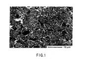
- FIG. 1 shows a scanning electron microscope (SEM) photograph of the surface of the current collector.
- This carbonaceous material film had carbonaceous material particles having an average particle size of 5 ⁇ m. Also, fine carbonaceous material particles having a particle size of 0.1 to 0.5 ⁇ m and coarse carbonaceous material particles having a particle size of 2 to 10 ⁇ m were mixed at a weight ratio of 50 : 50.
- a total solid type measurement cell was assembled using the obtained current collector, and the following electrode characteristics were used in evaluation.
- This measurement cell was a three-electrode cell formed as follows. As shown in FIG. 2, a polyacrylonitrile (PAN)-based thermoplastic gel electrolyte sheet 12 cutting into a size of 2 cm ⁇ 2 cm, was overlapped on a collector 11 and the residual portion of this collector 11 was exposed for the lead connection. In addition, two metal lithium foils 13 and 14 each having a size of 2 cm ⁇ 1 cm were placed on the electrolyte film 12 with a spacing of 1 mm, and adhered to the film. After that, lead electrodes 15 and 16 made of stainless steel plates were attached to the metal lithium foils 13 and 14, respectively, and the two sides of the resultant structure were sandwiched by glass plates 17 and 18.
- PAN polyacrylonitrile
- the PAN-based thermoplastic gel electrolyte film 12 described above was formed as follows. That is, a 20 wt% of a acrylonitrile-methylacrylate copolymer (PAN-MA) and a 1 : 1 solvent mixture, containing 1 mol/L of lithium tetrafluoroborate (LiBF 4 ), of propylene carbonate (PC) and ethylene carbonate (EC) were mixed. The mixture dissolved at 150°C was poured into a stainless steel tray, and slowly cooled. Then, an electrolyte gel sheet of 0.2 to 0.5 mm in thickness was obtained.
- PAN-MA acrylonitrile-methylacrylate copolymer
- LiBF 4 lithium tetrafluoroborate
- PC propylene carbonate
- EC ethylene carbonate
- a three-electrode measurement cell was assembled following the same procedures as in Example 1 except that an untreated Al foil was used as a current collector.
- Example 1 and Comparative Example 1 were evaluated by using a cyclic voltammetry method (CV method) and an AC impedance method (AC method).
- FIG. 3 shows the results of the CV measurement of the three-electrode measurement cell of Example 1.
- FIGS. 4 and 5 show the results of the AC impedance measurements of Example 1 and Comparative Example 1, respectively.
- FIG. 5 shows that in the three-electrode cell of Comparative Example 1 in which the collector made of an Al foil was incorporated, electron transfer in the collector interface did not easily occur.
- Carbon-based conductive paint ink (EB-815 (trade name) manufactured by Acheson (Japan) Ltd.) was used as a slurry.
- This ink has a composition containing 5 to 20 wt% of artificial graphite, 5 to 20 wt% of carbon black, 5 to 20 wt% of amidoimide resin, 0 to 1 wt% of butyral resin, and N-methylpyrrolidone solvent.
- a carbonaceous material film of 5 to 20 ⁇ m thickness was formed on the surface of the conductive substrate made of an Al foil.
- This carbonaceous material film had carbonaceous material particles having an average particle size of 10 ⁇ m.
- fine carbonaceous material particles having a particle size of 0.05 to 0.5 ⁇ m and coarse carbonaceous material particles having a particle size of 5 to 20 ⁇ m were mixed at a weight ratio of 1 : 2.
- This evaluation electrode was used to form a three-electrode type electrolytic solution cell having a reference electrode made of a lithium metal and a counter electrode made of a platinum plate, and the following electrochemical measurements were performed.
- a 1 : 1 solvent mixture containing 1 mol/L of lithium tetrafluoroborate (LiBF 4 ), of propylene carbonate (PC) and ethylene carbonate (EC)- was used.
- Potential scanning was repetitively performed at a potential sweep rate of 2 mV/sec within a potential range of 2.0 to 4.8 V (vs. Li/Li + ).
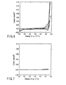
- FIG. 6 shows the obtained current response curves (CV curves).
- the potential window widened whenever scanning was repeated.
- a potential range of 2.5 to 4.3 V vs. Li/Li + no electrode reaction of the collector itself of Example 2 occurred. So, this electrode can be used as an electrode for electrolysis at a potential within this range.
- a three-electrode type electrolysis cell was constructed following the same procedures as in Example 2 except that a collector made of an untreated Al foil (H8079) was used, and the same electrochemical measurements as in Example 2 were performed.
- the obtained current potential response curve (CV curves) is shown in FIG. 7.
- Example 2 the collector of Example 2 in which a predetermined carbonaceous material film was formed on the surface of an Al foil had superior electricity collecting characteristics for electrolysis.
- a collector was manufactured by forming a carbonaceous material on the surface of a conductive substrate following the same procedures as in Example 2 except that a 15- ⁇ m thick titanium (Ti) foil was used as the conductive substrate.
- This collector was used to form a three-electrode type electrolytic solution cell and perform electrochemical measurements following the same procedures as in Example 2. Consequently, characteristics similar to Example 2 in which an Al foil was used as the conductive substrate were obtained.
- a collector was manufactured by forming a carbonaceous material on the surface of a conductive substrate following the same procedures as in Example 2 except that a 15 ⁇ m thick nickel (Ni) foil was used as the conductive substrate.
- This collector was used to form a three-electrode type electrolytic solution cell and perform electrochemical measurements following the same procedures as in Example 2. Consequently, characteristics similar to Example 2 in which an Al foil was used as the conductive substrate were obtained.
- An untreated Al foil was dipped in an aqueous alizarin(1,2-dihydroxyanthraquinone) solution for 1 hr to form an alizarin-aluminum complex undercoat on the surface.
- a collector was manufactured following the same procedures as in Example 2 except that a carbonaceous material was formed on the surface of this undercoat. The formation of this undercoat made the adhesion of the obtained collector higher than that obtained by surface roughing which is normally performed.
- the obtained collector was used to form a three-electrode type electrolytic solution cell and perform electrochemical measurements following the same procedures as in Example 2. Consequently, characteristics similar to Example 2 in which an Al foil was used as the conductive substrate were obtained.
- Collectors were manufactured by forming carbonaceous material films on the surfaces of conductive substrates following the same procedures as in Example 2 except that an aluminum punching metal and mesh metal were used as the conductive substrates. These collectors were used to form three-electrode type electrolytic solution cells and perform electrochemical measurements following the same procedures as in Example 2. Consequently, both the collectors had characteristics similar to Example 2 in which an Al foil was used as the conductive substrate.
- ⁇ -BL ⁇ -butyl lactone
- DMcT 2,5-dimercapto-1,3,4-thiadiazole
- ⁇ -BL 2 : 1 : 10 (weight ratio) and having a viscosity of 9 to 15 Pa ⁇ s.
- ⁇ -BL ⁇ -butyl lactone
- DMcT 2,5-dimercapto-1,3,4-thiadiazole
- the surface of the carbonaceous material film on one side of the collector formed in Example 2 was coated with the first ink for positive electrode material at 5 to 10 ⁇ m thick by using a bar coater, and the ink layer was dried in vacuum at 60°C for 2 hrs. Subsequently, the surface of this first electrode material layer was coated with the second ink for electrode material at 10 to 100 ⁇ m thick, and the ink layer was dried in a vacuum at 60°C for 2 to 12 hrs. In this manner, a composite positive electrode was manufactured.
- the obtained positive electrode was cut into a size of 10 to 50 mm.
- the entire surface of a sample was insulated by being coated with a silicone adhesive, except for a portion at a distance of 5 mm from one end and a circular portion (at a distance of 5 mm from the other end) 5 mm in diameter as an evaluation window, thereby forming an evaluation electrode.
- the entire coating layer on the exposed portion at one end was removed with a knife, and a lead wire was connected to this portion by a clip.
- This evaluation electrode was used to manufacture a three-electrode type electrolytic solution cell having a lithium metal reference electrode and platinum plate counter electrode, and the following electrochemical measurements were performed.
- a 1 : 1 solvent mixture containing 1 mol/L of lithium tetrafluoroborate (LiBF 4 ), of propylene carbonate (PC) and ethylene carbonate (EC) was used.
- FIG. 9 shows the cyclic voltammogram at 10 mV/sec potential sweep rate of the evaluation electrode.
- the polyaniline functions as an electrode reaction catalyst to accelerate the redox reaction of DMcT.
- FIG. 10 shows the potential-time relationship when electrolysis was performed at a current density with which the charge/discharge rate was equivalent to 2 C.
- FIG. 10 reveals that the collector of Example 8 can be used even at high charge/discharge rate.
- the surface of one side of the collector obtained in Example 2 was coated with the ink for the composite positive electrode material at 250 to 300 ⁇ m thick by using a bar coater, and the ink layer was dried at 100°C for 10 min. In this way, a 100 to 200 ⁇ m thick positive electrode sheet in which the composite positive electrode material layer having an area of 2 cm ⁇ 2 cm was formed on the one-side surface of the collector was manufactured.
- the resultant material was mixed in a mortar to prepare a viscous liquid material. This liquid material was evenly cast in a stainless steel tray, heated by a hot plate at 120°C, and cooled, thereby manufacturing a gel electrolyte sheet.
- a test cell shown in FIG. 11 was assembled by using the positive electrode sheet, the gel electrolyte sheet having an area of 2 cm ⁇ 2 cm, and a negative electrode formed by making a nickel foil to carry a metal lithium foil having an area of 2 cm ⁇ 2 cm.
- this test cell includes a positive electrode 25, gel electrolyte sheet 26, negative electrode 29, and two glass plates 30a and 30b.
- the positive electrode 25 has a collector 23 and positive electrode material layer 24.
- the collector 23 is manufactured by forming carbonaceous material films 22a and 22b on the both-side surfaces of a conductive substrate 21 made of an Al foil.
- the positive electrode layer 24 is carried on a one-side surface of the collector 23 and has an area of 2 cm ⁇ 2 cm.
- the gel electrolyte sheet 26 is overlapped on the positive electrode material layer 24 of the positive electrode 25.
- the negative electrode 29 has a structure in which a metal lithium foil 28 having an area of 2 cm ⁇ 2 cm is carried on a nickel foil 27 such that this metal lithium foil 28 is in contact with the electrolyte sheet 26.
- the glass plates 30a and 30b sandwich these positive electrode 25, electrolyte sheet 26, and negative electrode 29 by using a clip (not shown). Note that the collector 23 and nickel foil 27 are extended in opposite directions in order to extract an current.
- This test cell was assembled in an argon ambient containing water and having a dew point of -90°C or less and an oxygen concentration of 1 ppm or less, in a glove box (manufactured by Miwa Seisakusho Ltd.) entirely fullfielded with argon.
- Example 9 The obtained test cell of Example 9 was subjected to a charge/discharge test under the following conditions.
- test cell was placed in the glove box containing the argon ambient having a dew point of -90°C or less and an oxygen concentration of 1 ppm or less.
- a charge/discharge test was conducted at a charge/discharge rate of 0.2 C and a charge/discharge depth of 80% by using a charge/discharge test apparatus (manufactured by IWATSU ELECTRIC CO., LTD.).
- FIG. 12 shows the values of charge/discharge capacities of the test cell of Example 9 as a function of the number of cycles.
- FIG. 13 shows the charge/discharge characteristic at the 25th cycle.
- a test cell was assembled by stacking, in the order named, a positive electrode 43 having a structure in which a positive electrode material layer 42 was formed on one surface of a collector 41, a gel electrolyte sheet 44 having an area of 2 cm ⁇ 2 cm, a metal lithium foil 45 having an area of 2 cm ⁇ 2 cm as a negative electrode, and a nickel foil 46 for carrying this lithium foil 45, and sandwiching the stacked electrodes with two glass plates 47a and 47b.
- the positive electrode 43 was manufactured by forming a positive electrode material layer 42 (thin layer) of polyaniline.(PAn) available from NITTO DENKO CORP. in an area of 2 cm ⁇ 2 cm on one surface of a collector 41 (the thickness of carbonaceous material film was 7 ⁇ m) obtained in Example 2 described earlier (Example 10-1), or by forming a positive electrode material layer 42 (thin layer) of poly-2-methoxyaniline-s-sulfonic acid (PMAS) available from NITTO DENKO CORP. in an area of 2 cm ⁇ 2 cm on one surface of the same collector (Example 10-2).
- PMAS poly-2-methoxyaniline-s-sulfonic acid
- Test cells were assembled following the same procedures as in Example 10-1 except that a structure (Comparative Example 3-1) in which a thin layer of PAn. available from NITTO DENKO CORP. was formed on one-side surface of a collector made of a copper foil and a structure (Comparative Example 3-2) in which a thin layer of PMAS available from NITTO DENKO CORP. was formed on the same collector were used as positive electrodes.
- Each test cell was placed in a glove box containing an argon ambient having a dew point of -90°C or less and an oxygen concentration of 1 ppm or less.
- the charge/discharge test was conducted at a charge/discharge rate of 0.2 C and a charge/discharge depth of 80% by using a charge/discharge test apparatus (manufactured by IWATSU ELECTRIC CO., LTD.).
- Example 10-1 which included the positive electrode obtained by coating the collector having the carbonaceous material film formed on it with the thin PAn film.
- Comparative Example 3-1 which included the positive electrode obtained by coating the copper foil collector with the thin PAn film, oxidation of copper occurred also on the collector when the thin PAn film oxidized, so no satisfactory secondary battery characteristics could be obtained. This is so because the surface of the copper collector dissolved.
- the test cell of Example 10-2 which included the positive electrode obtained by coating the collector having the carbonaceous material film formed on it with the thin PMAS film has a theoretical capacity and energy density smaller than those of the test cell of Example 10-1 which included the positive electrode coated with the thin PAn film, and had charge/discharge characteristics slightly inferior to those of the test cell of Comparative Example 3-1 which included the positive electrode obtained by coating the copper foil collector with the thin PAn film.
- the stable charge/discharge cycles were obtained from this test cell of Example 10-2.
- polyaniline manufactured by NITTO DENKO CORP. and DMcT manufactured by Tokyo Kasei were dissolved in an N-methylpyrrolidone solvent. Furthermore, a sulfur powder was added, and the resulting mixture was stirred to prepare an ink solution. Note that this ink solution had a composition in which the weight ratio of polyaniline : DMcT was 1 : 30 and the amount of sulfur was varied within a predetermined range.
- the resulting ink solution was cast by using an applicator at a thickness of 60 ⁇ m on the collector obtained in Example 2, and dried in a vacuum at 80°C for 3 hrs, thereby manufacturing a positive electrode.
- test cell shown in FIG. 11 was assembled in the same manner as in Example 9. This test cell was subjected to a charge/discharge test under the following conditions.
- Charging was performed at a fixed current density until the cell voltage reached to 4.25 V. After that, the voltage was held at 4.25 V until the charging was completed. After the charging was thus completed, the circuit was opened for 30 min in order to estimate the magnitude of the overvoltage. Discharging was performed with a constant current and terminated when the cell voltage lowered to 1.2 V. The circuit was opened for 30 min after performing the discharge. The details were as follows. The charging current density was 0.25 mA/cm 2 in all cycles, and the 31st to 36th cycles were used as evaluation ones. The upper-limit cutoff voltage was 4.25 V. After the cell voltage reached 4.25 V, charging was continued at this fixed potential of 4.25 V until completion. The charging time was 6 hr.
- the 31st and 32nd cycles were performed at a current density of 0.12 mA/cm 2
- the 33rd and 34th cycles were performed at a current density of 0.25 mA/cm 2
- the 35th and 36th cycles were performed at a current density of 0.50 mA/cm 2 .
- the lower-limit cutoff voltage was set at 1.0 V, and the discharge was completed when the cell voltage lowered to 1.0 V.
- This charge/discharge test was conducted in a glove box entirely replaced with argon. By this charge/discharge test, FIG. 15 showing the terminal voltage during discharge in the 31st to 36th cycles was obtained.
- the test cell of Example 11 hardly changed the discharge voltage and discharge capacity even when the current density was changed in the 31st to 36th cycles, i.e., a discharge capacity close to 400 mAh/g was obtained at a discharge voltage of about 3.5 V. Accordingly, the redox reaction of the active material in the positive electrode is presumably satisfactorily fast at a current density of 0.25 mA/cm 2 or less. The charge/discharge efficiency was 90% or more.
- a collector coated with a 30- ⁇ m thick carbonaceous material film was manufactured following the same procedures as in Example 2 except that a spray gun was used as the coating method.
- a spray gun was used as the coating method.
- MPY-3 5,6-dithia-4,5,6,7-tetrahydro-2H-isoindole
- the redox behavior of its polymer (poly(MPY-3)) were evaluated by using cyclic voltammetry.
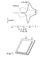
- FIG. 16 shows cyclic voltammograms when poly(MPY-3) and polypyrrol polymerized to the same extent as this poly(MPY-3) were electrochemically measured as comparative compounds.
- a redox reaction was observed in the thin poly(MPY-3) film in a potential region more positive than in the thin polypyrrol film. Also, the energy density of poly(MPY-3) was larger than that of polypyrrol.
- poly(MPY-3) has superior characteristics as a positive electrode material of a polymer secondary battery, and, when combined with the collector coated with the carbonaceous material film described above, can realize a positive electrode capable of increasing the electrical energy extractable per weight.
- a 10 to 300 nm thick copper film was formed using a sputtering apparatus (SPF-210H (trade name) manufactured by ANELVA CORPORATION). Subsequently, this thin copper film on the collector was coated with an ink solution containing (DMcT), polyaniline, carbon black, and NMP at a weight ratio of 2 : 1 : 0.2 : 30 by using a bar coater. The ink layer was dried at 100°C to form a 30 to 150 ⁇ m thick positive electrode material layer, thereby manufacturing a positive electrode.
- SPPF-210H trade name
- the obtained positive electrode was used to assemble a battery having a size of 2 cm ⁇ 2 cm shown in FIG. 14 described previously, following the same procedures as in Example 10. After the elapse of one hour, a clip was removed, and, as shown in FIG. 17, the battery was wrapped in an aluminum laminated film, and the opening was melted to assemble a thin lithium secondary battery having an outer package structure. These series of operations were performed in an argon ambient containing water and having a dew point of -90°C or less and an oxygen concentration of 1 ppm or less, in a glove box entirely replaced with argon.
- the obtained thin lithium secondary battery was subjected to a charge/discharge test at a charge/discharge rate of 0.2 C and a charge/discharge depth of 80% by using a charge/discharge test apparatus (manufactured by IWATSU ELECTRIC CO., LTD.).
- this secondary battery had superior charge/discharge characteristics equivalent to a secondary battery using a collector made of copper.
- a 10 nm thick gold film was formed using a sputtering apparatus (SPF-210H (trade name) manufactured by ANELVA CORPORATION).
- SPF-210H trade name
- This collector was dipped in an aqueous solution containing DMcT for 1 hr to bond DMcT molecules to the surface of the thin gold film.
- the resultant collector was repetitively alternately dipped in an aqueous solution containing cuprous chloride and aqueous DMcT solution to form molecular stacked films of DMcT and copper, thereby manufacturing a positive electrode.
- Example 14 The obtained positive electrode of Example 14 was used to manufacture an evaluation electrode, assemble a three-electrode type electrolysis cell, and evaluate the characteristics, following the same procedures as in Example 9. Consequently, CV curves possessed similar shape and characteristics to FIG. 9 explained earlier were obtained.
- the present invention can provide a positive electrode for lithium secondary battery, which achieves high energy density, by making it possible to use a conductive material, such as aluminum, which is several times as light in weight as copper, as a collector which carries a positive electrode material layer containing an organic sulfide compound as an active material.
- the present invention can provide a high-capacity, high-performance lithium secondary battery having the positive electrode described above.
Landscapes
- Chemical & Material Sciences (AREA)
- Chemical Kinetics & Catalysis (AREA)
- Electrochemistry (AREA)
- General Chemical & Material Sciences (AREA)
- Engineering & Computer Science (AREA)
- Materials Engineering (AREA)
- Composite Materials (AREA)
- Inorganic Chemistry (AREA)
- Crystallography & Structural Chemistry (AREA)
- Manufacturing & Machinery (AREA)
- Cell Electrode Carriers And Collectors (AREA)
- Secondary Cells (AREA)
- Battery Electrode And Active Subsutance (AREA)
Abstract
Description
a collector obtained by forming a carbonaceous material film on the surface of a conductive substrate, and
a positive electrode material layer carried on the carbonaceous material film side of the collector and containing an organic sulfide compound as a main active material.
a positive electrode having a collector formed by forming a carbonaceous material film on the surface of a conductive substrate, and a positive electrode material layer carried on the carbonaceous material film side of the collector and containing an organic sulfide compound as a main active material,
an electrolyte, and
a negative electrode having a material which storages and releases lithium.
-(CH2CH2O)p]COC(R)=CH2
Accordingly, a positive electrode for lithium secondary battery having excellent performance is expected to be realized by forming, on this collector, a positive electrode material layer containing an organic sulfide compound as a main active material.
DMcT : PAn : γ-BL = 2 : 1 : 10 (weight ratio) and having a viscosity of 9 to 15 Pa·s.
The
Claims (13)
- A positive electrode for lithium secondary battery comprising:a collector obtained by forming a carbonaceous material film on the surface of a conductive substrate; anda positive electrode material layer carried on the carbonaceous material film side of said collector and containing an organic sulfide compound as a main active material.
- A positive electrode for lithium secondary battery according to claim 1, wherein said main active material further contains a π electron conjugate conductive polymer.
- A positive electrode for lithium secondary battery according to claim 1, wherein said main active material further contains a π electron conjugate conductive polymer and inorganic sulfur compound.
- A positive electrode for lithium secondary battery according to claim 1, wherein said conductive substrate is made of a material selected from the group consisting of aluminum, titanium, nickel, and alloys of these metals, each of which has a density less than copper.
- A positive electrode for lithium secondary battery according to claim 1, wherein said carbonaceous material film contains at least one type of carbonaceous material selected from the group consisting of graphite materials such as natural graphite and artificial graphite, coke, carbon fibers, mesophase carbon microbeads, a graphitization retardant material as a carbide of synthetic resin, and a carbon nanotube, and a binder having resistance to an organic solvent.
- A positive electrode for lithium secondary battery according to claim 5, wherein said binder is a polymer or polymerization precursor consisting primarily of amidoimide or imide.
- A positive electrode for lithium secondary battery according to claim 5 or 6, wherein said carbonaceous material film has a form which contains carbonaceous material particles having an average particle size of 20 nm to 30 µm, and in which fine carbonaceous material particles having a particle size of 0.02 to less than 1.0 µm and coarse carbonaceous material particles having a particle size of 1 to 30 µm are mixed at a weight ratio of 85 : 15 to 15 : 85.
- A positive electrode for lithium secondary battery according to claim 1, wherein said conductive substrate is made of aluminum, and said carbonaceous material film formed on said conductive substrate has a thickness of 0.1 to 20 µm.
- A positive electrode for lithium secondary battery according to claim 5, wherein said carbonaceous material film is formed by coating the surface of said conductive substrate with a slurry which contains a carbonaceous material, a binder having resistance to an organic solvent, and an organic solvent by using any of reverse coating, gravure coating, roll knife coating, comma coating, bar coating,-and spray coating, and drying the coating film.
- A positive electrode for lithium secondary battery according to claim 1, wherein fine particles and/or ultrafine particles of a conductive material are adhered to the surface of said carbonaceous material film.
- A lithium secondary battery comprising:a positive electrode having a collector formed by forming a carbonaceous material film on the surface of a conductive substrate, and a positive electrode material layer carried on the carbonaceous material film side of said collector and containing an organic sulfide compound as a main active material;an electrolyte; anda negative electrode having a material which absorbs and releases lithium.
- A lithium secondary battery according to claim 11, wherein said main active material further contains a π electron conjugate conductive polymer.
- A lithium secondary battery according to claim 11, wherein said main active material further contains a π electron conjugate conductive polymer and inorganic sulfur compound.
Applications Claiming Priority (3)
| Application Number | Priority Date | Filing Date | Title |
|---|---|---|---|
| JP2001152759A JP3733404B2 (en) | 2001-05-22 | 2001-05-22 | Positive electrode for lithium secondary battery and lithium secondary battery |
| JP2001152759 | 2001-05-22 | ||
| PCT/JP2002/004925 WO2002095848A1 (en) | 2001-05-22 | 2002-05-22 | Anode for lithium secondary battery and lithium secondary battery |
Publications (2)
| Publication Number | Publication Date |
|---|---|
| EP1391948A1 true EP1391948A1 (en) | 2004-02-25 |
| EP1391948A4 EP1391948A4 (en) | 2010-01-06 |
Family
ID=18997382
Family Applications (1)
| Application Number | Title | Priority Date | Filing Date |
|---|---|---|---|
| EP02771769A Withdrawn EP1391948A4 (en) | 2001-05-22 | 2002-05-22 | ANODE FOR LITHIUM SECONDARY BATTERY AND RELATED LITHIUM SECONDARY BATTERY |
Country Status (14)
| Country | Link |
|---|---|
| US (1) | US20030148187A1 (en) |
| EP (1) | EP1391948A4 (en) |
| JP (1) | JP3733404B2 (en) |
| KR (1) | KR100496090B1 (en) |
| CN (1) | CN1242500C (en) |
| AU (1) | AU2002308873B2 (en) |
| BR (1) | BR0205397A (en) |
| CA (1) | CA2420001A1 (en) |
| CZ (1) | CZ2003859A3 (en) |
| HU (1) | HUP0700136A2 (en) |
| MX (1) | MXPA03003444A (en) |
| PL (1) | PL374493A1 (en) |
| TW (1) | TW544962B (en) |
| WO (1) | WO2002095848A1 (en) |
Cited By (6)
| Publication number | Priority date | Publication date | Assignee | Title |
|---|---|---|---|---|
| WO2009069250A1 (en) * | 2007-11-30 | 2009-06-04 | Toyota Jidosha Kabushiki Kaisha | Electrode collector for battery and use thereof |
| EP2081244A1 (en) | 2008-01-15 | 2009-07-22 | Samsung Electronics Co., Ltd. | Electrode, Lithium Battery, Method of Manufacturing Electrode, and Composition for Coating Electrode |
| WO2012175486A1 (en) * | 2011-06-21 | 2012-12-27 | Fraunhofer-Gesellschaft zur Förderung der angewandten Forschung e. V. | Cathode unit for an alkaline metal/sulphur battery having an optimised arrester structure |
| US9263731B2 (en) | 2010-11-12 | 2016-02-16 | A123 Systems Llc | High performance lithium or lithium ion cell |
| US9350017B2 (en) | 2010-11-12 | 2016-05-24 | A123 Systems Llc | High performance lithium or lithium ion cell |
| EP4465372A1 (en) * | 2023-05-17 | 2024-11-20 | Automotive Cells Company SE | Electrode sheet for a battery cell and associated manufacturing process |
Families Citing this family (49)
| Publication number | Priority date | Publication date | Assignee | Title |
|---|---|---|---|---|
| AU2002366928A1 (en) * | 2001-12-21 | 2003-07-09 | Sanyo Electric Co., Ltd. | Non-aqueous electrolytic secondary battery |
| JP2005050669A (en) * | 2003-07-28 | 2005-02-24 | Tdk Corp | Electrode and electrochemical element using the same |
| US7348102B2 (en) * | 2004-03-16 | 2008-03-25 | Toyota Motor Corporation | Corrosion protection using carbon coated electron collector for lithium-ion battery with molten salt electrolyte |
| US7521153B2 (en) * | 2004-03-16 | 2009-04-21 | Toyota Motor Engineering & Manufacturing North America, Inc. | Corrosion protection using protected electron collector |
| DE102004013634A1 (en) * | 2004-03-18 | 2005-10-06 | Ormecon Gmbh | Composition useful for forming a coating useful in electrical double layer capacitors to form electronic apparatus and power supplies comprises a mixture of a conductive polymer in colloidal form and carbon |
| EP1744388A4 (en) * | 2004-03-30 | 2010-08-25 | Noboru Oyama | ACTIVE REDOX REVERSIBLE ELECTRODE AND SECONDARY BATTERY INCLUDING SAID ELECTRODE |
| KR100591792B1 (en) * | 2004-06-16 | 2006-06-26 | 경상대학교산학협력단 | Current collector-anode integrated superelastic metal-metal sulfide element for battery |
| JP5153056B2 (en) * | 2004-12-24 | 2013-02-27 | パナソニック株式会社 | Manufacturing method of composite current collector and electrode for non-aqueous electrolyte secondary battery or electric double layer capacitor containing carbon nanofiber |
| WO2006085691A1 (en) | 2005-02-10 | 2006-08-17 | Showa Denko K.K | Secondary-battery cutrrent collector, secondary-battery cathode, secondary-battery anode, secondary battery and production method thereof |
| JP2006324288A (en) * | 2005-05-17 | 2006-11-30 | Tdk Corp | Method for producing electrode for electrochemical capacitor |
| US8262746B2 (en) * | 2005-08-26 | 2012-09-11 | Sanyo Electric Co., Ltd. | Method of producing electrode plate filled with active material, method of producing battery using thereof |
| FR2891402B1 (en) * | 2005-09-29 | 2010-03-26 | Univ Toulouse | DISPERSE SOLUTION OF CARBON MATERIALS FOR THE MANUFACTURE OF CURRENT COLLECTORS. |
| WO2007043515A1 (en) * | 2005-10-11 | 2007-04-19 | Showa Denko K.K. | Electric double layer capacitor |
| CN100387695C (en) * | 2005-11-19 | 2008-05-14 | 燕山大学 | Mesophase carbon alloy lubricating additive and preparation method thereof |
| KR100740715B1 (en) | 2006-06-02 | 2007-07-18 | 경상대학교산학협력단 | Current collector-electrode integrated Ti-Ni alloy-Ni sulfide element |
| JP5372318B2 (en) * | 2006-07-14 | 2013-12-18 | パナソニック株式会社 | Method for manufacturing electrochemical capacitor |
| US8002921B2 (en) * | 2008-05-29 | 2011-08-23 | Corning Incorporated | Electrodes for electric double layer devices |
| WO2010002002A1 (en) * | 2008-07-03 | 2010-01-07 | Dic株式会社 | Secondary battery and carbon ink for conductive auxiliary layer of the secondary battery |
| US20100159366A1 (en) * | 2008-08-15 | 2010-06-24 | Massachusetts Institute Of Technology | Layer-by-layer assemblies of carbon-based nanostructures and their applications in energy storage and generation devices |
| JP5029540B2 (en) | 2008-09-01 | 2012-09-19 | ソニー株式会社 | Positive electrode active material, positive electrode and non-aqueous electrolyte secondary battery using the same |
| CZ2008572A3 (en) * | 2008-09-19 | 2010-02-10 | He3Da S.R.O. | Lithium battery with spatial electrode type and method of production |
| JP2010086788A (en) * | 2008-09-30 | 2010-04-15 | Nippon Zeon Co Ltd | Method of manufacturing electrode for electrochemical element |
| JP5608990B2 (en) * | 2009-03-12 | 2014-10-22 | トヨタ自動車株式会社 | Current collector foil, battery, vehicle, battery-operated device, and current collector foil manufacturing method |
| KR20110035906A (en) * | 2009-09-30 | 2011-04-06 | 가부시키가이샤 한도오따이 에네루기 켄큐쇼 | Capacitor |
| CN101807683A (en) * | 2010-04-28 | 2010-08-18 | 常州市宙纳新能源科技有限公司 | Positive electrode piece, negative electrode piece of lithium ion capacitance battery and manufacture method of two electrode pieces thereof |
| JP5561029B2 (en) * | 2010-08-27 | 2014-07-30 | トヨタ自動車株式会社 | battery |
| US9882202B2 (en) | 2010-11-26 | 2018-01-30 | Ulvac, Inc. | Positive electrode for lithium-sulfur secondary battery and method of forming the same |
| DE102011002720A1 (en) * | 2011-01-14 | 2012-07-19 | Robert Bosch Gmbh | cathode composition |
| KR101199177B1 (en) | 2011-06-15 | 2012-11-07 | 삼성에스디아이 주식회사 | Secondary battery |
| KR101271991B1 (en) | 2011-07-06 | 2013-06-05 | 삼성에스디아이 주식회사 | Secondary battery |
| US20140315095A1 (en) * | 2011-07-29 | 2014-10-23 | Uacj Foil Corporation | Collector, electrode structure, nonaqueous electrolyte battery, and electrical storage device |
| CN102315454A (en) * | 2011-08-02 | 2012-01-11 | 大连丽昌新材料有限公司 | A kind of preparation of composite collector and the application in the lithium ion flow battery thereof |
| JP5281706B2 (en) * | 2011-10-25 | 2013-09-04 | 株式会社神戸製鋼所 | Current collector, current collector manufacturing method, electrode, and secondary battery |
| KR101357241B1 (en) | 2011-10-28 | 2014-02-03 | 한국과학기술원 | Electrode including mixed composites of self-assembled electrode active material and graphene layer, and secondary battery using the same, and the fabrication method thereof |
| TWI482340B (en) | 2011-12-14 | 2015-04-21 | Ind Tech Res Inst | Electrode assembly of lithium secondary battery |
| CN103187576B (en) | 2011-12-28 | 2015-07-29 | 清华大学 | Collector, electrochemical cell electrode and electrochemical cell |
| JP6115914B2 (en) * | 2013-03-13 | 2017-04-19 | 国立研究開発法人産業技術総合研究所 | Sulfur-modified nitrile group-containing copolymer resin and use thereof |
| JP2013145761A (en) * | 2013-04-08 | 2013-07-25 | Nippon Zeon Co Ltd | Method for manufacturing electrode for electrochemical element |
| US20140315084A1 (en) * | 2013-04-18 | 2014-10-23 | Nokia Corporation | Method and apparatus for energy storage |
| JP6394253B2 (en) * | 2014-10-03 | 2018-09-26 | 株式会社豊田中央研究所 | Non-aqueous secondary battery electrode, method for producing the same, and non-aqueous secondary battery |
| TWI597313B (en) * | 2015-12-24 | 2017-09-01 | 財團法人工業技術研究院 | Conductive composition and capacitor utilizing the same |
| CN108885947B (en) * | 2016-03-22 | 2021-01-05 | 松下知识产权经营株式会社 | Positive electrode for electrochemical device with lead member, method for producing the same, and electrochemical device |
| WO2017195331A1 (en) | 2016-05-12 | 2017-11-16 | エリーパワー株式会社 | Positive electrode for non-aqueous electrolyte secondary battery, and non-aqueous electrolyte secondary battery |
| KR20170136971A (en) | 2016-06-02 | 2017-12-12 | 주식회사 엘지화학 | Carbon-based fiber sheet and lithium-sulfur battery comprising the same |
| WO2017209383A1 (en) * | 2016-06-02 | 2017-12-07 | 주식회사 엘지화학 | Carbon-based fiber sheet and lithium-sulfur battery including same |
| CN106653135A (en) * | 2017-02-04 | 2017-05-10 | 陈柏瑞 | Pi electron orbital semiconductor type quantum battery |
| CN111146441B (en) * | 2018-11-06 | 2021-05-04 | Sk新技术株式会社 | Positive electrode active material for lithium secondary battery and method for producing the same |
| CN112186197B (en) * | 2019-07-01 | 2024-06-18 | 宁德时代新能源科技股份有限公司 | Positive electrode current collector, positive electrode sheet and electrochemical device |
| FR3143203B1 (en) * | 2022-12-07 | 2025-12-26 | Renault Sas | Electrode and electrolyte for lithium-ion battery incorporating a polymer compound |
Family Cites Families (10)
| Publication number | Priority date | Publication date | Assignee | Title |
|---|---|---|---|---|
| US5478676A (en) * | 1994-08-02 | 1995-12-26 | Rexam Graphics | Current collector having a conductive primer layer |
| JPH08109196A (en) * | 1994-08-19 | 1996-04-30 | Matsushita Electric Ind Co Ltd | Composite electrode and manufacturing method thereof |
| US6210831B1 (en) * | 1997-12-19 | 2001-04-03 | Moltech Corporation | Cathodes comprising electroactive sulfur materials and secondary batteries using same |
| US6110619A (en) * | 1997-12-19 | 2000-08-29 | Moltech Corporation | Electrochemical cells with cationic polymers and electroactive sulfur compounds |
| US6153337A (en) * | 1997-12-19 | 2000-11-28 | Moltech Corporation | Separators for electrochemical cells |
| EP0973180A3 (en) * | 1998-07-14 | 2003-11-19 | Asahi Glass Company Ltd. | Secondary power source |
| US6576370B1 (en) * | 1999-04-26 | 2003-06-10 | Matsushita Electric Industrial Co., Ltd. | Positive electrode and lithium battery using the same |
| US6503432B1 (en) * | 2000-03-02 | 2003-01-07 | E. I. Du Pont De Nemours And Company | Process for forming multilayer articles by melt extrusion |
| JP2001273901A (en) * | 2000-03-27 | 2001-10-05 | Yuasa Corp | Electrode material |
| JP2002110237A (en) * | 2000-08-17 | 2002-04-12 | Samsung Sdi Co Ltd | Positive active material composition for lithium-sulfur battery, method for producing the same, and lithium-sulfur battery |
-
2001
- 2001-05-22 JP JP2001152759A patent/JP3733404B2/en not_active Expired - Fee Related
-
2002
- 2002-05-21 TW TW091110672A patent/TW544962B/en not_active IP Right Cessation
- 2002-05-22 WO PCT/JP2002/004925 patent/WO2002095848A1/en not_active Ceased
- 2002-05-22 CZ CZ2003859A patent/CZ2003859A3/en unknown
- 2002-05-22 CN CNB028017684A patent/CN1242500C/en not_active Expired - Fee Related
- 2002-05-22 MX MXPA03003444A patent/MXPA03003444A/en unknown
- 2002-05-22 BR BR0205397-7A patent/BR0205397A/en not_active IP Right Cessation
- 2002-05-22 CA CA002420001A patent/CA2420001A1/en not_active Abandoned
- 2002-05-22 KR KR10-2003-7000950A patent/KR100496090B1/en not_active Expired - Fee Related
- 2002-05-22 AU AU2002308873A patent/AU2002308873B2/en not_active Ceased
- 2002-05-22 EP EP02771769A patent/EP1391948A4/en not_active Withdrawn
- 2002-05-22 PL PL02374493A patent/PL374493A1/en unknown
- 2002-05-22 HU HU0700136A patent/HUP0700136A2/en unknown
-
2003
- 2003-02-13 US US10/365,816 patent/US20030148187A1/en not_active Abandoned
Cited By (11)
| Publication number | Priority date | Publication date | Assignee | Title |
|---|---|---|---|---|
| WO2009069250A1 (en) * | 2007-11-30 | 2009-06-04 | Toyota Jidosha Kabushiki Kaisha | Electrode collector for battery and use thereof |
| US8852810B2 (en) | 2007-11-30 | 2014-10-07 | Toyota Jidosha Kabushiki Kaisha | Electrode collector for battery and use thereof |
| EP2081244A1 (en) | 2008-01-15 | 2009-07-22 | Samsung Electronics Co., Ltd. | Electrode, Lithium Battery, Method of Manufacturing Electrode, and Composition for Coating Electrode |
| US9397330B2 (en) | 2008-01-15 | 2016-07-19 | Samsung Electronics Co., Ltd. | Electrode, lithium battery, method of manufacturing electrode, and composition for coating electrode |
| US9263731B2 (en) | 2010-11-12 | 2016-02-16 | A123 Systems Llc | High performance lithium or lithium ion cell |
| US9350017B2 (en) | 2010-11-12 | 2016-05-24 | A123 Systems Llc | High performance lithium or lithium ion cell |
| EP2638597B1 (en) * | 2010-11-12 | 2017-01-18 | A123 Systems LLC | High performance lithium or lithium ion cell |
| WO2012175486A1 (en) * | 2011-06-21 | 2012-12-27 | Fraunhofer-Gesellschaft zur Förderung der angewandten Forschung e. V. | Cathode unit for an alkaline metal/sulphur battery having an optimised arrester structure |
| US10090528B2 (en) | 2011-06-21 | 2018-10-02 | Fraunhofer-Gesellschaft Zur Forderung Der Angewandten Forschung E.V. | Cathode unit for an alkaline metal/sulfur battery having an optimised arrester structure |
| EP4465372A1 (en) * | 2023-05-17 | 2024-11-20 | Automotive Cells Company SE | Electrode sheet for a battery cell and associated manufacturing process |
| WO2024236191A1 (en) * | 2023-05-17 | 2024-11-21 | Automotive Cells Company Se | Electrode sheet for a battery cell and associated manufacturing process |
Also Published As
| Publication number | Publication date |
|---|---|
| CN1242500C (en) | 2006-02-15 |
| TW544962B (en) | 2003-08-01 |
| CN1463473A (en) | 2003-12-24 |
| KR20030029112A (en) | 2003-04-11 |
| JP3733404B2 (en) | 2006-01-11 |
| CA2420001A1 (en) | 2002-11-28 |
| JP2002352796A (en) | 2002-12-06 |
| HUP0700136A2 (en) | 2007-06-28 |
| PL374493A1 (en) | 2005-10-31 |
| WO2002095848A1 (en) | 2002-11-28 |
| BR0205397A (en) | 2003-07-01 |
| AU2002308873B2 (en) | 2004-12-23 |
| CZ2003859A3 (en) | 2004-04-14 |
| EP1391948A4 (en) | 2010-01-06 |
| US20030148187A1 (en) | 2003-08-07 |
| MXPA03003444A (en) | 2003-08-19 |
| KR100496090B1 (en) | 2005-06-17 |
Similar Documents
| Publication | Publication Date | Title |
|---|---|---|
| AU2002308873B2 (en) | Anode for lithium secondary battery and lithium secondary battery | |
| KR100896556B1 (en) | Positive electrode material for lithium secondary cell | |
| KR101264485B1 (en) | Positive electrode of lithium secondary battery and method for producing the same | |
| US7241534B2 (en) | Lithium polymer secondary cell | |
| CN110582872A (en) | Lithium battery cathode and manufacturing method | |
| JP4834030B2 (en) | Positive electrode for lithium secondary battery and lithium secondary battery using the same | |
| JP2019212619A (en) | Manufacturing method of electrode active material layer, manufacturing method of electrode for lithium ion battery, and manufacturing method for lithium ion battery | |
| CN113273010A (en) | Composite solid electrolyte and composite solid electrolyte secondary battery | |
| JP5326575B2 (en) | Method for producing polyradical compound-conductive substance complex | |
| JP3500245B2 (en) | Gel-like solid electrolyte secondary battery | |
| JP2005340165A (en) | Positive electrode material for lithium secondary battery | |
| CN1290221C (en) | Polymeric solid electrolyte and lithium secondary cell using the same | |
| JP2004185865A (en) | Lithium ion battery, method of manufacturing the same, and negative electrode structure | |
| JP4058753B2 (en) | Polymer solid electrolyte and polymer solid electrolyte battery | |
| KR100766886B1 (en) | Lithium secondary battery | |
| JP2024122209A (en) | Cured material for lithium ion secondary battery, negative electrode for lithium ion secondary battery, and lithium ion secondary battery | |
| JP3588131B2 (en) | Positive electrode for secondary battery and secondary battery using the electrode | |
| JP2011159568A (en) | Positive electrode for nonaqueous secondary battery, and nonaqueous secondary battery using the same | |
| JPH04218261A (en) | Secondary battery | |
| WO2023162833A1 (en) | Electrode and battery | |
| KR20260029553A (en) | Binder for lithium rechargeable battery, electrode including the same and lithium rechargeable battery including the same | |
| HK1157938A (en) | Electrochemical cells with tabs |
Legal Events
| Date | Code | Title | Description |
|---|---|---|---|
| PUAI | Public reference made under article 153(3) epc to a published international application that has entered the european phase |
Free format text: ORIGINAL CODE: 0009012 |
|
| 17P | Request for examination filed |
Effective date: 20030228 |
|
| AK | Designated contracting states |
Kind code of ref document: A1 Designated state(s): AT BE CH CY DE DK ES FI FR GB GR IE IT LI LU MC NL PT SE TR |
|
| AX | Request for extension of the european patent |
Extension state: AL LT LV MK RO SI |
|
| RAP1 | Party data changed (applicant data changed or rights of an application transferred) |
Owner name: OYAMA, NOBORU Owner name: MITSUI & CO., LTD. Owner name: FUJI JUKOGYO KABUSHIKI KAISHA |
|
| RAP1 | Party data changed (applicant data changed or rights of an application transferred) |
Owner name: OYAMA, NOBORU Owner name: FUJI JUKOGYO KABUSHIKI KAISHA |
|
| A4 | Supplementary search report drawn up and despatched |
Effective date: 20091203 |
|
| 17Q | First examination report despatched |
Effective date: 20100312 |
|
| RAP1 | Party data changed (applicant data changed or rights of an application transferred) |
Owner name: FUJI JUKOGYO KABUSHIKI KAISHA Owner name: OYAMA, NOBORU |
|
| STAA | Information on the status of an ep patent application or granted ep patent |
Free format text: STATUS: THE APPLICATION IS DEEMED TO BE WITHDRAWN |
|
| 18D | Application deemed to be withdrawn |
Effective date: 20141202 |