Technical Field
-
The present invention relates to a ceramic heater for a
semiconductor producing/inspecting device used in a ceramic
heater, an electrostatic chuck, a chuck top plate for a wafer
prober, and the like mainly in the semiconductor industry.
Background Art
-
Conventionally, a heater using a metal base such as
stainless steel or aluminum alloy has been used in semiconductor
producing/inspecting devices or other devices, examples of which
include an etching device and a chemical gas phase growth device
and the like.
-
However, such a metal heater has the following problems.
-
First, the thickness of the ceramic substrate must be as
thick as about 15 mm since the heater is made of metal. This
is because in a thin metal plate, a warp, a strain and the like
are caused owing to thermal expansion thereof resulting from
heating so that a silicon wafer placed on the metal plate is
damaged or inclined. However, when the thickness of the ceramic
substrate is made thick, a problem that the heater becomes heavy
and bulky arises.
-
Heating temperature is controlled by changing the amount
of voltage or electric current applied to the heating elements.
However, since the metal plate is thick, the temperature of the
ceramic substrate does not follow the change in the voltage or
electric current amount promptly. Thus, a problem that the
temperature is not easily controlled occurs.
-
On the contrary to this, JP Kokai Hei 11-40330 and the
like discloses a ceramic heater wherein a nitride ceramic or
carbide ceramic having a high thermal conductivity and a large
strength is used instead of metal and heating elements formed
by sintering metal particles are provided on a surface of a ceramic
substrate made of such a ceramic.
-
Even when such a heater expands thermally at the time of
heating, a warp, a strain or the like is not easily caused in
its ceramic substrate. The temperature-following character to
a change in applied voltage or electric current amount is also
good.
Summary of the Invention
-
However, in the process of producing a semiconductor, a
corrosive gas such as chlorine-based gas or fluorine-based gas
is used as an etching gas or a cleaning gas. Therefore, in the
case where a ceramic heater having a structure as described above
is used, there is caused a problem that electrode members such
as external terminals, or conductive wires corrode so that the
performance of the ceramic heater deteriorates.
-
In order to solve such a problem, a manner for protecting
electrode members, such as external terminals or conductive wires,
from corrosive gas and the like is adopted by: bonding a
disc-shaped ceramic to a cylindrical ceramic body through a
ceramic bonding layer; and providing external terminals and the
like inside the cylindrical ceramic body, as described in JP
Kokai Hei 2000-114355 or Japanese Patent gazette No. 2783980.
-
Fig. 11 is a sectional view schematically showing a ceramic
heater wherein a silicon wafer is placed at a ceramic substrate
having such a structure.
-
In this ceramic heater 50, a cylindrical body 57 is bonded
to a bottom face 51b in the vicinity of the center of a ceramic
substrate 51 having a disc shape through a ceramic bonding layer
61. Since the cylindrical ceramic body 57 is formed so as to
adhere closely to a bottom plate (not shown) of a supporting
case, the inside and outside of the cylindrical ceramic body
57 are completely isolated from each other.
-
A conductor circuit 58, which is extended toward the
vicinity of the center of the ceramic substrate 51 at which the
cylindrical ceramic body 57 is bonded, is formed between a
resistance heating element 52 and the bottom face 51b, and the
end portion of the resistance heating element is connected to
one end portion of the conductor circuit 58 through a via hole
530.
-
This conductor circuit 58 is formed in order to extend
the end portion of the resistance heating element to the central
portion. Immediately under the other end portion of the
conductor circuit 58 are formed a conductor-filled through hole
53 and a blind hole 59 for exposing the conductor-filled through
hole 53. This conductor-filled through hole 53 is connected
to an external terminal 63 having a T-shaped tip through a solder
layer (not shown).
-
In the case where the end portion of the resistance heating
element exists inside the cylindrical ceramic body 57, no via
hole or conductor circuit is necessary. Consequently, the
conductor-filled through holes 53 are directly formed at the
end portions of the resistance heating element, and the end
portions are connected to external terminals 63 through the
solder layer.
-
Sockets 65 having conductive wires 630 are attached to
these external terminals 63, and the conductive wires 630 are
led out from a through hole (not shown) formed in a bottom plate
(not shown), and are connected to a power source and the like
(not shown).
-
As described above, in this ceramic heater 50, the
cylindrical ceramic body 57 is bonded to the ceramic substrate
51 through the ceramic bonding layer 61, and the cylindrical
ceramic body 57 is formed untill a bottom plate (case wall) of
a non-shown supporting case; therefore, the inside and outside
of the cylindrical ceramic body 57 are in the state that they
are completely isolated from each other.
-
Accordingly, wires and the like inside the cylindrical
ceramic body 57 are not corroded by corrosive gas and the like.
-
However, when this method is adopted, there is caused a
new problem that temperature evenness in a heating face of the
ceramic substrate deteriorates, resulted from escape of heat
toward gas inside the cylindrical ceramic body by the
introduction of inert gas or the like into the cylindrical ceramic
body or escape of heat through a bonding portion for the ceramic
substrate and the cylindrical ceramic body.
-
In light of above-mentioned problems, the present inventor
made eager investigation to obtain a ceramic heater wherein:
electrode members such as external terminals or conductive wires
are not corroded, and dispersion in temperature in a heating
face of a ceramic substrate is small, at the time of heating
in the.process of producing a semiconductor. As a result, the
present inventor has found out that, by: constituting a ceramic
heater for a semiconductor producing/inspecting device wherein
a resistance heating element is formed inside a ceramic
substrate; and further forming a power feeding terminal at the
outside of a wafer-heating region of the ceramic substrate, a
portion forced to contact corrosive gas can be kept inside the
wafer-heating region and thus a semiconductor wafer can be evenly
heated without exposing external terminals or conductive bodies
for connecting the external terminals to resistance heating
elements to the corrosive gas. Thus, the present invention has
been completed.
-
That is, a ceramic heater for a semiconductor
producing/ inspecting device according to the present invention
comprises: a ceramic substrate; and a resistance heating element
formed inside the ceramic substrate, wherein a power feeding
terminal is formed to be exposed at the outside of a wafer-heating
region of the above-mentioned ceramic substrate.
-
The wafer-heating region is desirably a portion extending
from a face opposing a wafer, to a face opposite to the face
opposing a wafer, of the ceramic substrate. That is, the
above-mentioned wafer-heating region is a region used to heat
a semiconductor wafer, and is desirably a portion (see Fig. 9)
traversed in the process of dragging a place where the
semiconductor wafer is to be placed, which is in a face opposing
the semiconductor wafer of the ceramic substrate, to the
underlying face (the face opposite to the face opposing the
semiconductor wafer), vertically.
-
In a ceramic heater having a desired structure among the
ceramic heaters for semiconductor producing/inspecting devices
of the present invention, the above-mentioned ceramic substrate
is constituted by: a disc-shaped substrate; and a convex portion
formed on its side face, and the connection between the resistance
heating element inside the above-mentioned ceramic substrate
and an external terminal is made through a conductor inside the
convex portion.
-
In another ceramic heater having a desired structure, the
ceramic substrate is a disc-shaped substrate body having a
diameter larger than the wafer-heating region thereof, and an
external terminal is formed at the outside of the wafer-heating
region.
-
It is desired that a bottomed hole is formed in a side
face of the above-mentioned ceramic substrate and a temperature
measuring element is inserted into the bottomed hole.
-
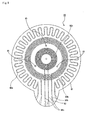
As shown in Figs. 1 to 3, in one of the ceramic heaters
having the above-mentioned desired structures, its ceramic
substrate has a shape wherein a disc-shaped substrate and a convex
portion are formed to be integrated with each other, and the
connection between a resistance heating element and an external
terminal is made through a conductor inside the convex portion.
Therefore, in the case where the ceramic heater is fixed to a
supporting case and the resultant is used as a hot plate unit
in the process of producing a semiconductor, electrode members
such as the external terminal, and conductive wires can be
arranged outside the atmosphere of corrosive gas. For this
reason, the electrode members and the conductive wires are not
forced to contact the corrosive gas, and a drop in the performance
of the ceramic heater can be prevented.
-
Furthermore, even when in the ceramic heater of the present
invention, the electrode members and the conductive wires cannot
be arranged outside the corrosive gas atmosphere in the process
of producing a semiconductor, the electrode members and the like
are located to be concentrated in the vicinity of the convex
portion of the ceramic substrate. Therefore, by forming a
protective member made of a ceramic or the like capable of blocking
the corrosive gas in this portion, the electrode members can
easily be protected from the corrosive gas and the corrosion
of the electrode members can be prevented.
-
In the ceramic heater of the present invention, it is
unnecessary to provide the cylindrical ceramic body 57 for
protecting electrode members such as external terminals, and
conductive wires from corrosive gas, in the vicinity of the center
portion of the ceramic substrate 51, as in the ceramic heater
50 shown in Fig. 11. Therefore, it is unnecessary to consider:
temperature unevenness in the heating face, which is resulted
from: escape of heat toward the gas inside the cylindrical ceramic
body 57 by the introduction of inert gas or the like into the
cylindrical ceramic body 57; or escape of heat through a bonding
portion for the ceramic substrate 51 and the cylindrical ceramic
body 57, and thus a semiconductor wafer, which is an object to
be heated, can be evenly heated.
-
In a ceramic heater having another structure, its ceramic
substrate is a disc-shaped substrate body having a diameter
larger than the wafer-heating region thereof, wherein an external
terminal is formed at the outside of the wafer-heating region.
-
In this structure, it is sufficient as long as a chamber
is formed so as to cover the ceramic substrate. Also, if the
terminal is made exposed from a side face of the ceramic substrate,
a conductive wire for connecting the resistance heating element
to the terminal is not corroded by any corrosive gas since the
conductive wire exists inside the ceramic substrate.
-
Also, since the ceramic heater is a single disc as a whole,
the heat capacity can be made point-symmetric as compared with
the case of forming the convex portion. Thus, radiation of heat
is evenly performed and, this structure is favorable. The
diameter of the ceramic substrate is desirably set to not less
than 1.5 times larger than the wafer-heating region.
Brief Description of the Drawings
-
- Fig. 1 is a bottom view schematically showing one example
of a ceramic heater according to the present invention.
- Fig. 2 is a partial sectional view of the ceramic heater
shown in Fig. 1 taken in the direction of A-A line.
- Fig. 3 is a partial sectional view of the ceramic heater
shown in Fig. 1 taken in the direction of B-B line.
- Fig. 4 is a bottom view schematically showing another
example of the ceramic heater according to the present invention.
- Fig. 5 is a sectional view schematically showing one
example of the case where the ceramic heater according to the
present invention is fixed to a supporting case.
- Fig. 6 is a partial sectional view schematically showing
one example of the case where a protective member is formed in
the ceramic heater according to the present invention.
- Fig. 7 is a bottom view schematically showing a structure
of bottomed holes in the ceramic heater shown in Fig. 1 and
temperature measuring elements.
- Fig. 8 is a plan view showing a ceramic heater having a
convex portion of a semicircular shape.
- Figs. 9 are bottom views schematically showing another
embodiment of the ceramic heater according to the present
invention.
- Figs. 10(a) to (d) are sectional views schematically
showing parts of the process of producing the ceramic heater
shown in Fig. 1.
- Fig. 11 is a sectional view schematically showing one
example of a conventional ceramic heater.
- Fig. 12(a) is a thermoviewer photograph obtained by
observing the heating face of the ceramic heater according to
Example 1, and Fig. 12 (b) is a thermoviewer photograph obtained
by observing the heating face of the ceramic heater according
to Comparative Example 1.
- Fig. 13 is a graph showing the relationship between the
in-face temperatures and the thermal conductivities thereof of
the ceramic heater according to Examples 4 to 8 and Comparative
Examples 2 to 6.
- Fig. 14 is a graph showing the relationshipbetween applied
electric powers and temperatures in the case where the
temperatures of the ceramic heaters according to Example 1 and
Comparative Example 1 were raised.
| | Explanation of Symbols |
| 10, 30, 50 | ceramic heater |
| 11, 31, 51 | ceramic substrate |
| 11a, 51a | heating face | | |
| 11b, 51b | bottom face | | |
| 12, 32, 52 | resistance heating element |
| 120, 180 . | conductor containing paste layer |
| 23, 63 | external terminal |
| 14, 54 | bottomed hole |
| 15, 55 | through hole for a lifter pin |
| 16, 56 | lifter pin |
| 18, 58 | conductor circuit |
| 20 | protective member |
| 21 | bonding layer |
| 13, 53 | conductor-filled through hole |
| 130, 170 | filled layer |
| 29, 69 | semiconductor wafer |
| 70 | green sheet |
-
Detailed Disclosure of the Invention
-
The following will describe the present invention
according to embodiments thereof.
-
A ceramic heater for a semiconductor producing/inspecting
device according to an embodiment is a ceramic heater for a
semiconductor producing/inspecting device wherein resistance
heating elements comprising a plurality of circuits are formed
inside a ceramic substrate, in which the ceramic substrate is
formed of a disc-shaped substrate and a convex portion of a
substantially rectangular shape, these are integrated to
constitute a main face on a single plane, and the connection
between the resistance heating elements and external terminals
is made at a side face of the convex portion.
-
The embodiment of the ceramic heater of the present
invention will be described with reference to drawings.
-
In the following description, a ceramic heater for a
semiconductor producing/inspecting device may be referred to
simply as a ceramic heater.
-
Fig. 1 is a bottom view which schematically shows a ceramic
heater of the present invention.
-
Fig. 2 is a partial sectional view of the ceramic heater
shown in Fig. 1 taken in the direction of A-A line, and Fig.
3 is a partial sectional view of the ceramic heater shown in
Fig. 1 taken in the direction of B-B line.
-
In this ceramic heater, resistance heating elements are
formed inside its ceramic substrate.
-
In the following description, the A-A line direction and
the B-B line direction may be referred to as the longitudinal
direction and the lateral direction, respectively.
-
As shown in Fig. 1, in the ceramic heater 10, its ceramic
substrate 11 has a shape formed of a disc-shaped substrate and
a convex portion of a substantially rectangular shape.
-
The disc-shaped substrate and the convex portion of a
substantially rectangular shape are integrated with each other
to constitute a main face on a single plane. The thickness of
side faces of the ceramic substrate 11 is wholly even.
-
In the following description, the convex portion of a
substantially rectangular shape may be referred to simply as
the convex portion. The shape of the convex portion is not
limited to any rectangular shape, and may be a semicircular and
the like.
-
Fig. 8 shows a ceramic heater 80 having a convex portion
of a semicircular shape. This ceramic heater 80 is constructed
in the same manner as the ceramic heater 10 shown in Fig. 1 except
that the convex portion has a semicircular shape.
-
The diameter of the disc-shaped substrate which
constitutes the ceramic substrate 11 in the ceramic heater 10
of the present invention is desirably 200 mm or more. This is
based on the following reasons: as the ceramic heater has a larger
diameter, the temperature of a semiconductor wafer 29 easily
becomes more uneven when the wafer is heated, and thus the
construction of the present invention functions more
effectively; and also a semiconductor wafer having a large
diameter can be placed on the substrate having such a large
diameter.
-
In particular, the diameter of the substrate which
constitutes the ceramic substrate 11 is desirably 12 inches (300
mm) or more. This is because, this size becomes the main current
of semiconductor wafers in the next generation.
-
About the substantially rectangular convex portion of the
ceramic substrate 11, the length thereof in the A-A line direction
(longitudinal direction) is desirably 310 to 600 mm.
-
If the length is less than 310 mm, electrode members cannot
be arranged outside the atmosphere of corrosive gas since the
distance between the semiconductor wafer 29 and the electrode
members cannot be made sufficiently long. When the length
exceeds 600 mm, the temperature of the convex portion drops so
that dispersion in temperature is generated in the heating face
of the ceramic substrate 11.
-
On the other hand, the length in the B-B line direction
(lateral direction) of the convex portion is desirably 5 to 340
mm.
-
When the length is less than 5 mm, it is difficult to form
resistance heating elements 12 or external terminals 23 in the
convex portion. When the length exceeds 340 mm, the interval
between the resistance heating elements 12 is too wide in the
convex portion so that the temperature of the convex portion
drops. Consequently, dispersion in temperature is caused in
the heating face of the ceramic substrate 11.
-
The thickness of the ceramic substrate 11 which constitutes
the ceramic heater 10 of the present invention is desirably 25
mm or less. This is because when the thickness of the ceramic
substrate 11 exceeds 25 mm, the temperature-following character
deteriorates. Moreover, the thickness is desirably 0.5 mm or
more. When the thickness is smaller than 0.5 mm, the strength
itself of the ceramic substrate 11 drops so that the ceramic
substrate is easily damaged. Moreover, it is difficult to form
via holes or conductor circuits 18 under the resistance heating
elements 12.
-
More desirably, the thickness exceeds 1.5 mm and 5 mm or
less. When the thickness is larger than 5 mm, heat is not easily
conducted so that heating efficiency tends to deteriorate. On
the other hand, when the thickness is 1.5mm or less, heat conducted
in the ceramic substrate 11 does not diffuse sufficiently so
that dispersion in temperature may be caused in the heating face.
Additionally, the strength of the ceramic substrate 11 drops
so that the ceramic substrate 11 may be damaged.
-
Furthermore, in the ceramic substrate 10, the resistance
heating elements 12 (12a to 12c) are formed inside the ceramic
substrate 11 in order to perform heating in such a manner that
the temperature in the whole of the heating face 11a will be
even.
-
That is, a resistance heating element 12a having a
repetition pattern of winding lines is arranged in the outermost
circumference of the ceramic heater 10, and resistance heating
elements 12b and 12c including circuits of concentrically
circular patterns are arranged at a constant intervals and inside
the resistance heating element 12a.
-
As the pattern of the resistance heating element 12a in
the outermost circumference in the ceramic heater 10 of the
present invention, there can be used, for example, a
concentrically circular pattern, a spiral pattern, an
eccentrically circular pattern or the like as well as the
repetition pattern of the winding lines, shown in Fig. 1. Also,
these may be used together.
-
By making the pattern of the resistance heating element
12a formed in the outer circumference as a pattern divided in
the circumferential direction, minute temperature control can
be performed in the outermost circumference, where the
temperature drops easily, of the ceramic heater 10. Thus,
dispersion in the temperature of the ceramic heater 10 can be
suppressed. Furthermore, the pattern of the resistance heating
elements divided in the circumferential direction may be formed
not only in the outermost circumference but also in the inside
thereof.
-
About the resistance heating elements 12b and 12c formed
in the internal circumference portion of the ceramic substrate
11, there can also be used, for example, repetition patterns
of winding lines, spiral patterns, eccentrically circular
patterns or other patterns besides the concentrically circular
patterns.
-
In the ceramic heater 10, each of end portions of the
resistance heating elements 12a to 12c is extended to a side
face of the convex portion of the ceramic substrate 11.
-
The pattern of resistance heating element 12a is as
follows: a part of the repetition pattern of the winding lines
is cut such that end portions of the two cut ends are extended
perpendicularly to the side face of the convex portion of the
ceramic substrate 11.
-
In the resistance heating element 12b, one of the end
portions thereof is formed at the outer side of the concentrically
circular pattern, and the end portion is extended perpendicularly
to the side face of the convex portion of the ceramic substrate
11 in the same manner as in the case of the resistance heating
element 12a. Whereas, the other end portion is formed at the
inner side of the concentrically circular pattern in order to
prevent the generation of cooling spots and the like. Hence,
a via hole 17 is made immediately under this end portion, and
a conductor circuit 18b is formed under the via hole 17, whereby
the end portion of the resistance heating element is extended
to the side face of the convex portion of the ceramic substrate
11.
-
At the resistance heating element 12c, via holes 17 are
formed immediately under the end portion thereof at the outer
side of the concentrically circular pattern and the end portion
thereof at the inner side thereof, and a conductor circuit 18c
is formed under the via holes 17, whereby the end portions of
the resistance heating element are extended to the side face
of the convex portion of the ceramic substrate 11.
-
That is, the end portions formed at the inner side of the
concentrically circular patterns are connected to the conductor
circuits 18b and 18c through the via holes 17.
-
In order to prevent intervals between the resistance
heating elements from being sparse in the vicinity of the bonding
part between the disc-shaped substrate and the substantially
rectangular convex portion of the ceramic substrate 11, the cut
portion of the repetition pattern of the winding lines, which
is the resistance heating element 12a formed in the outer
circumference, may be made narrower than the one shown in the
figure.
-
In order to avoid overlapping of the repetition pattern
of the winding lines with the conductor circuit 18b or 18c
three-dimensionally in this case, a via hole may be made
immediately above the cut portion at the repetition pattern of
the winding lines, thereby forming conductor circuits having
a structure wherein end portions are extended from the upper
part of this via hole as a starting point to the side face of
the convex portion such that the cut portion of the repetition
pattern of the winding lines becomes narrow.
-
The conductor circuits 18 are formed in order to extend
the end portions of the resistance heating elements to the side
face of the convex portion of the ceramic substrate 11. About
the material, the structure and so on of the conductor circuits
18, it is desired to use the same as those of the resistance
heating elements 12.
-
In the ceramic heater of the present invention, the
resistance heating elements 12 are formed inside the ceramic
substrate 11 so that the surfaces of the resistance heating
elements are not oxidized. Thus, it is unnecessary to cover
the surface.
-
Furthermore, conductor-filled through holes 13 are formed
at the end portions of the conductor circuits 18 and the end
portions of the resistance heating elements extended to the side
face of the convex portion of the ceramic substrate 11, and blind
holes for making the conductor-filled through holes exposed are
formed. Moreover, external terminals 23 are inserted into the
blind holes 19, and they are bonded with a brazing material (not
shown).
-
Furthermore, for example, sockets (not shown) having
conductive wires are attached to the external terminals 23, and
the conductive wires are connected to a power source or the like.
-
The external terminals 23 equipped for the connection to
the power source are attached to the resistance heating elements
12 through solder. In the case where the external terminals
23 are connected thereto, an alloy such as silver-lead, lead-tin
or bismuth-tin can be used as the solder. The thickness of the
solder layer is desirably 0.1 to 50 µm. This is because this
range is a range sufficient for maintaining the connection based
on the solder.
-
Examples of the external terminals 23 include external
terminals made of kovar or Ni.
-
The external terminals 23 are desirably formed on a side
face or a lower side face of the ceramic substrate, as shown
in Fig. 6.
-
As shown in Figs. 2 and 3, through holes 15 are formed
in the ceramic substrate 10 and, also, lifter pins are passed
through the through holes 15 so that the semiconductor wafer
29, which is an object to be heated, can be supported and heated
in the state where the wafer 29 is positioned a predetermined
distance apart from the heating face of the ceramic heater 10.
-
By not the lifter pins 16 but supporting pins 22 formed
on the heating face of the ceramic heater, the semiconductor
wafer 29 can be supported and heated in the state that the wafer
29 is positioned a predetermined distance apart from the heating
face of the ceramic heater 10.
-
In the ceramic substrate 11 of the present invention, when
the semiconductor wafer 29, which is an object to be heated,
is positioned apart from the heating face of the ceramic substrate
11 by means of the lifter pins 15 or the supporting pins 22,
it is desired to hold the wafer 29 in the state where the wafer
29 is positioned 5 to 5000 µm apart. This is because: when the
distance is less than 5 µm, the distance becomes too short, thus
the temperature of the semiconductor wafer is affected by
temperature distribution in the ceramic substrate 11 and made
uneven.
-
When the distance exceeds 5000 µm, the temperature of the
semiconductor wafer 29 does not rise easily. As a result, in
particular, the temperature of the outer circumferential portion
of the semiconductor wafer 29 becomes low. The object to be
heated and the heating face of the ceramic substrate are desirably
positioned from 5 to 500 µm, more desirably from 20 to 200 µm
apart from each other.
-
Fig. 4 is a bottom view which schematically shows a ceramic
heater of another embodiment of the present invention.
-
In the ceramic heater 30, resistance heating elements 32
(32a to 32c) are formed inside a ceramic substrate 31 so as to
perform heating in such a manner that the temperature in the
whole of a heating face 31a will be even. These resistance
heating elements 32a to 32c are formed of circuits having
concentrically circular patterns. Each of the end portions of
the resistance heating elements 32a to 32c is extended to a side
face of a convex portion of the ceramic substrate 31.
-
The end portion formed at the outer side of the resistance
heating element 32a, which is one of the concentrically circular
patterns, is extended perpendicularly to the side face of the
convex portion of the ceramic substrate 31. A via hole is formed
immediately under the end portion formed at the inner side, and
a conductor circuit 38a is formed, through the via hole,
immediately under the end portion, whereby the end portion of
the resistance heating element is extended to the side face of
the convex portion of the ceramic substrate 31.
-
In the resistance heating elements 32b and 32c, via holes
are formed immediately under the end portions formed at the outer
sides of the concentrically circular patterns and the end
portions formed at the inner sides thereof, and conductor
circuits 38b and 38c are formed under the via holes, thereby
extending the end portions of the resistance heating elements
to the side face of the convex portion of the ceramic substrate
31.
-
About the ceramic substrate 30 shown in Fig. 4, structures
other than the patterns of the resistance heating elements are
similar to that in the ceramic substrate 10 shown in Fig. 1.
Thus, description thereof will not be repeated.
-
Fig. 5 is a sectional view which schematically shows one
example of the case where the ceramic heater 10 of the present
invention is fixed to a supporting case to function as a hot
plate unit.
-
In the hot plate unit 1, through holes are formed near
the outer circumference portion of the ceramic heater 10, and
bolts 72 are passed through the through holes. Ends of the bolts
72 are fixed to the bottom of the supporting case and, also,
the bolts are fixed by means of nuts 73 erected to the lower
part of the ceramic substrate 11. Consequently, the ceramic
heater 10 is supported and fixed to the inside of the supporting
case 41 by means of the bolts 72 which are vertically erected
on the bottom of the supporting case 41.
-
In this case, the substantially rectangular convex portion
of the ceramic substrate 11 is positioned outside the upper part
of the supporting case.
-
The ceramic heater 10 is supported and fixed at the bottom
of the supporting case 41 in substantially parallel manner with
each other.
-
Furthermore, in this state, the side faces of the ceramic
heater 10 and an outer frame portion of the supporting case 41
are slightly separated to be brought into a non-contact state
with each other. Since the air functions as a heat insulating
material, heat does not escape easily from the side faces of
the ceramic heater 10.
-
External terminals 23 are connected through a solder layer
(not shown) to the end portions of the conductor circuits 18
which is connected through the via holes 17 to the resistance
heating elements 12. Sockets 25 having conductive wires 230
are attached to the external terminals 23, and the conductive
wires 230 are led out from the supporting case, so as to be
connected to a power source (not shown).
-
Incidentally, guide tubes 45 for protecting lifter pins
(not shown) are formed in the hot plate unit 1, and coolant
introducing pipes 39 are fixed to the bottom portion of the
supporting case 41 to make cooling possible.
-
In the case where the ceramic heater 10 of the present
invention is used as the hot plate unit 1 having the structure
shown in Fig. 5 in the process of producing a semiconductor,
the distance from a semiconductor wafer 29 to electrode members
such as the external terminals 23 and the like, or the conductive
wires 230 can be made long; therefore, the electrode members,
such as the external terminals 23 formed at the side face of
the convex portion of the ceramic substrate 11, and the conductive
wires 230 can be provided outside the atmosphere of corrosive
gas such as cleaning gas by putting the whole of the hot plate
unit except the convex portion into an air-tightly closed case
or by covering only the convex portion with a protective member
or the like. Thus, the electrode members are not forced to
contact the corrosive gas, and deterioration in the performance
of the ceramic heater can be prevented.
-
Additionally, in the ceramic heater of the present
invention, it is unnecessary to set, in the vicinity of the central
portion of the ceramic substrate, any cylindrical ceramic body
for protecting the electrode members such as the external
terminals, or the conductive wires from the corrosive gas, as
performed in the ceramic heater shown in Fig. 11. It is therefore
unnecessary to consider temperature unevenness in the heating
face, resulting from escape of heat toward the gas inside the
cylindrical ceramic body by the introduction of inert gas or
the like into the cylindrical ceramic body or escape of heat
through a bonding portion for the ceramic substrate and the
cylindrical ceramic body. Thus, the semiconductor wafer, which
is an object to be heated, can be evenly heated.
-
Besides, it is unnecessary to produce a ceramic sintered
body and subsequently perform the step of bonding the ceramic
substrate to any cylindrical ceramic body by re-firing or some
other operation as performed in the ceramic heater 50 of Fig.
11. Thus, the process of producing the ceramic heater can be
made simple.
-
Fig. 6 is a sectional view which schematically shows a
structure in the case where electrode members such as external
terminals 23 and the like, or conductive wires, which are formed
on a side face of a convex portion of a ceramic substrate 11,
are covered with a protective member 20.
-
The protective member 20 is desirably made of a material
having an insulating property and having such a heat-resistance
that the member is not deformed or reformed even when the ceramic
substrate 11 is heated, and is desirably a member made of an
oxide ceramic such as alumina, silica, mullite or cordierite,
a nitride ceramic such as aluminum nitride or silicon nitride,
a carbide ceramic such as silicon carbide, a corrosion-resistant
metal, or the like.
-
The protective member 20 is desirably brazed to the ceramic
substrate 11 through a bonding portion 21 made of a brazing
material. This is because the ceramic substrate 11 and the
protective member 20 are firmly fixed to each other. Thematerial
of the bonding portion 21 is not particularly limited, and
examplesthereofinclude brazing aluminum,brazing gold,brazing
silver, brazing phosphor copper, brazing brass, brazing nickel
and brazing palladium.
-
Further, a heat insulating ring may be used in the bonding
portion 21.
-
As the bonding portion 21, the following may be used:
brazing silver prescribed in JIS Z 3261-1976, brazing gold
prescribed in JIS Z 3266-1977, brazing palladium prescribed in
JIS Z 3267-1976, brazing brass prescribed in JIS Z 3262-1977,
brazing aluminum alloy prescribed in JIS Z 3263-1977, brazing
phosphor copper prescribed in JIS Z 3264-1977 , brazing phosphor
nickel prescribed in JIS Z 3265-1976, or the like.
-
Specifically, an example of brazing silver is an alloy
made of 44 to 46% by weight of Ag, 14 to 16% by weight of Cu,
14 to 18% by weight of Zn, and 23 to 35% by weight of Cd, an
example of brazing gold is an alloy made of 34.5 to 35.5% by
weight of Au, and 2.5 to 3.5% by weight of Ni, an example of
brazing palladium is an alloy made of 59.5 to 60.5% by weight
of Pd, and 39.5 to 40.5% by weight of Ni, and an example of brazing
brass is an alloy made of 46 to 49% by weight of Cu, 10 to 11%
by weight of Ni, and 0.3 to 1.0% by weight of Ag.
-
An example of brazing aluminum alloy is an alloy made of
0.25% or less by weight of Cu, 6.8 to 8.2% by weight of Si, 0.1%
or less by weight of Mn, 0.8% or less by weight of Fe and the
balance of Al, an example of brazing nickel is an alloy made
of 13.0 to 15.0% by weight of Cr, 2.7 to 4.0% by weight of B,
3. 0 to 5.0% by weight of Si, 4.0 to 5.0% by weight of Fe, 0.6
to 0.9% by weight of C, and the balance of Ni, and an example
of brazing phosphor copper is an alloy made of 4.8 to 5.3% by
weight of P, and the balance of Cu.
-
The thickness of the bonding portion 21 is desirably 0.1
to 5 mm. This is because, if the thickness is too large or too
small, the adhesiveness becomes poor.
-
Accordingly, even when the whole of the hot plate unit
1 including the electrode members such as the external terminals
23, or the conductive wires 230 is in the atmosphere of corrosive
gas in the process of producing a semiconductor, the electrode
members, such as the external terminals 23, or the conductive
wires 230 can easily be protected from the corrosive gas and
corrosion of the electrode members and the conductive wires can
be prevented by covering the electrode members and the conductive
wires 230 with the protective member 20 capable of blocking the
corrosive gas as shown in Fig. 6 since the electrode members
such as the external terminals 23 concentrate in the vicinity
of the convex portion of the ceramic substrate 11 in the ceramic
heater 10 of the present invention.
-
Fig. 7 is a bottom view which schematically shows a
structure of bottomed holes formed in the ceramic substrate 11,
and the like.
-
As shown in Fig. 7, the plurality of bottomed holes 14,
which are in parallel to the main face of the ceramic substrate
11 and have openings in the side face of the convex portion,
are formed in the ceramic substrate 11.
-
Temperature measuring elements 180 are inserted in the
bottomed holes 14.
-
The bottomed holes 14 are formed in such a manner that
their tips are positioned in portions the temperature of which
relatively easily becomes uneven, such as the central portion
of the ceramic substrate 11 and the outer circumference portion
thereof. Therefore, in the case where the temperature measuring
elements 180 are inserted into the bottomed holes 14 to measure
the temperature of the ceramic substrate, the temperature in
the heating face can be precisely measured.
-
As shown in Figs. 2 and 3, the temperature in the heating
face can be more precisely measured by making the bottomed holes
14 closer to the heating face 11a than the resistance heating
elements 12.
-
The openings of the bottomed holes 14 are provided in the
side face of the convex portion of the ceramic substrate 11;
therefore, portions where the temperature measuring elements
180 are exposed can be positioned outside the corrosive gas
atmosphere, in the process of producing a semiconductor, in the
same manner as in the case of the above-mentioned electrode
members and conductive wires. The portions where the
temperature measuring elements 180 are exposed are not forced
to contact the corrosive gas. Thus, deterioration in the
performance of the temperature measuring elements 180 can be
prevented.
-
The distance between the bottomed holes 14 and the heating
face 11a is desirably 0.1 mm to 1/2 of the thickness of the ceramic
substrate.
-
With this structure, temperature-measuring positions are
closer to the heating face 11a than the resistance heating
elements 12, so that the temperature of the semiconductor wafer
29 can be more precisely measured.
-
When the distance between the bottomed holes 14 and the
heating face 11a is less than 0.1 mm, heat radiates so that a
temperature distribution is formed in the heating face 11a. When
the distance exceeds 1/2 of the thickness, the ceramic substrate
is easily affected by the temperature of the resistance heating
elements 12 so that temperature-control cannot be performed.
Thus, a temperature distribution is formed in the heating face,
as well.
-
The diameter of the bottomed hole 14 is desirably 0.3
to 5 mm. This is because, when the diameter is too large, the
heat-radiating property becomes large. When the diameter is
too small, the processability deteriorates so that the distance
to the heating face 11a cannot be made even.
-
As shown in Fig. 7, a plurality of the bottomed holes 14
are desirably arranged linear-symmetrically with the center of
the ceramic substrate 11. This is because temperatures in the
entire heating face can be measured.
-
Examples of the temperature measuring elements 180 include
thermocouples, platinum temperature measuring resistors,
thermistors and the like.
-
Examples of the thermocouple include K-, R-, B-, S-, E-,
J- and T-type thermocouples and the like, as described in
JIS-C-1602 (1980). Of these, the K-type thermocouple is
preferred.
-
Desirably, the size of the connecting part of the
thermocouple is equal to or more than the strand diameter thereof,
and is 0.5 mm or less. This is because when the connecting part
is large, the heat capacity is large so that the responsibility
deteriorates. It is difficult to make the size thereof smaller
than the strand diameter.
-
The above-mentioned temperature measuring elements 180
may be bonded to the bottom of the bottomed holes 14 with brazing
gold, brazing silver or the like, or may be inserted into the
bottomed holes 14 followed by sealing up the holes with a
heat-resistant resin. The two may be used together.
-
Examples of the heat-resistant resin include
thermosetting resins, in particular, epoxy resin, polyimide
resin and bismaleimide-triazine resin and the like. These
resins may be used alone or in combination of two or more of
them.
-
As the above-mentioned brazing gold, desired is at least
one selected from an alloy of 37 to 80.5% by weight of Au and
63 to 19.5% by weight of Cu, and an alloy of 81.5 to 82.5% by
weight of Au and 18.5 to 17.5% by weight of Ni. These have a
melting temperature of 900°C or more, and are not easily melted
in high temperature regions.
-
Examples of the brazing silver include Ag-Cu types.
-
The following will describe the material, shape and so
on of the ceramic heater which constitutes the present invention
in more detail.
-
The ceramic which constitutes the ceramic heater of the
present invention is desirably a nitride ceramic or a carbide
ceramic.
-
Since a nitride ceramic or a carbide ceramic has a thermal
expansion coefficient smaller than metals and a far higher
mechanical strength than metals, the ceramic substrate thereof
does not warp or bend even when the thickness of the ceramic
substrate is made small. Therefore, the ceramic substrate can
be made thin and light. Since the thermal conductivity of the
ceramic substrate is high and the ceramic substrate itself is
thin, the surface temperature of the ceramic substrate follows
temperature change in the resistance heating elements promptly.
That is, the surface temperature of the ceramic substrate can
be controlled by changing the amount of voltage or electric
current to change the temperature of the resistance heating
elements.
-
Examples of the nitride ceramic include aluminum nitride,
silicon nitride, boron nitride and titaniumnitride and the like.
These may be used alone or in combination of two or more.
-
Examples of the carbide ceramic include silicon carbide,
zirconium carbide, titanium carbide, tantalum carbide and
tungsten carbide. These may be used alone or in combination
of two or more.
-
Of these, aluminum nitride is most preferred. This is
because its thermal conductivity is highest, that is, 180 W/m·
K and aluminum nitride has excellent temperature-following
character.
-
It is desired that the ceramic substrate of the present
invention contains carbon and the carbon content is from 200
to 5000 ppm. This is because the electrodes can be concealed
and black-body radiation is easily used.
-
The brightness of the ceramic substrate is desirably N6
or less as a value based on the rule of JIS Z 8721. This is
because the ceramic having such a brightness is excellent in
radiant heat capacity and the property of the concealing.
-
The brightness N is defined as follows: the brightness
of ideal black is made to 0; that of ideal white is made to 10;
respective colors are divided into 10 parts in the manner that
the brightness of the respective colors is recognized stepwise
between the brightness of black and that of white; and the
resultant parts are indicatedby symbols N0 to N10, respectively.
-
Actual measurement thereof is performed by comparison with
color charts corresponding to N0 to N10. One place of decimals
in this case is made to 0 or 5.
-
In the present invention, the resistance heating elements
are embedded in the ceramic substrate.
-
When the resistance heating elements are formed inside
the ceramic substrate, it is desired that the resistance heating
elements are formed at positions having a distance, from the
face opposite to the heating face, of 60% or less of the thickness.
In the case of exceeding 60%, heat conducted in the ceramic
substrate does not diffuse sufficiently since the resistance
heating elements are too near to the heating face. Thus, a
temperature distribution in the heating face is generated.
-
When the resistance heating elements are formed, a
plurality of heating element forming layers may be provided.
In this case, the patterns of the respective layers are desirably
in the state where any one of the resistance heating elements
is formed on some layer so as to be complementary to each other
and, when viewed from a position above the heating face, the
patterns are formed in all areas. An example of such a structure
is a staggered arrangement.
-
When the resistance heating elements are formed inside
the ceramic substrate, the thickness thereof is preferably 1
to 50 µm. The width of the resistance heating elements in the
ceramic substrate is preferably 5 to 20 µm.
-
The resistance value of the resistance heating elements
can be changed dependently on their width or thickness. The
above-mentioned ranges are however most practical. The
resistance value becomes larger as the resistance heating
elements become thinner and narrower. The thickness and the
width of the resistance heating elements become larger in the
case where the resistance heating elements are formed inside
the ceramic substrate. However, when the resistance heating
elements are formed inside, the distance between the heating
face and the resistance heating elements becomes short so that
the evenness of the temperature in the surface deteriorates.
Thus, it is necessary to make the width of the resistance heating
elements themselves large. Since the resistance heating
elements are formed inside, it is unnecessary to consider the
adhesiveness to the nitride ceramic or the like. Therefore,
it is possible to use a high melting point metal such as tungsten
or molybdenum, or a carbide of tungsten, molybdenum or the like.
Thus, the resistance value can be made high. Therefore, the
thickness itself may be made large in order to prevent
disconnection and the like. For these reasons, the resistance
heating elements are desirably made to have the above-mentioned
thickness and width.
-
By setting the position where the resistance heating
elements are formed in this manner, heat generated from the
resistance heating elements diffuses to the whole of the ceramic
substrate while the heat is conducted. Thus, a temperature
distribution in the face for heating an object to be heated (a
semiconductor wafer) is made even so that the temperatures of
respective portions of the object to be heated are made even.
-
The resistance heating elements may have a rectangular
section or an elliptical section. They desirably have a flat
section. From the flat section, heat is more easily radiated
toward the heating face. Thus, a temperature distribution in
the heating face cannot be easily generated.
-
The aspect ratio (the width of the resistance heating
element/the thickness of the resistance heating element) of the
section is desirably 10 to 5000.
-
Adjustment thereof into this range makes it possible to
increase the resistance value of the resistance heating elements
and keep the evenness of the temperature in the heating face.
-
In the case where the thickness of the resistance heating
elements is made constant, the amount of heat conducted toward
the heating face of the ceramic substrate becomes small when
the aspect ratio is smaller than the above-mentioned range. Thus,
a heat distribution similar to the pattern of the resistance
heating elements is generated in the heating face. On the other
hand, when the aspect ratio is too large, the temperature of
the portions just above the centers of the resistance heating
elements becomes high so that a heat distribution similar to
the pattern of the resistance heating elements is generated in
the heating face. Accordingly, when temperature distribution
is considered, the aspect ratio of the section is preferably
10 to 5000.
-
When the resistance heating elements are formed inside
the ceramic substrate, the aspect ratio is desirably 200 to 5000.
-
The aspect ratio becomes larger in the case where the
resistance heating elements are formed inside the ceramic
substrate. This is based on the following reason. When the
resistance heating elements are formed inside, the distance
between the heating face and the resistance heating elements
becomes short so that temperature evenness in the surface
deteriorates. It is therefore necessary to make the resistance
heating elements themselves flat.
-
A conductor containing paste used when the resistance
heating elements are formed is not particularly limited.
However, preferably, the paste contains a resin, a solvent, a
thickener or the like as well as metal particles or a conductive
ceramic for ensuring electric conductivity.
-
The above-mentioned metal particles are preferably made
of, for example, a noble metal (gold, silver, platinum or
palladium), lead, tungsten, molybdenum, nickel or the like.
Among them, the noble metal (gold, silver, platinum or palladium)
is more preferred. These may be used alone, but are desirably
used in combination of two or more. These metals are not
relatively easily oxidized, and have a resistance value
sufficient for generating heat.
-
Examples of the above-mentioned conductive ceramic
include carbides of tungsten and molybdenum. These may be used
alone or in combination of two or more.
-
The particle diameter of these metal particles or the
conductive ceramic particles is preferably from 0.1 to 100 µm.
When the particle diameter is too fine, that is, less than 0.1
µm, they are easily oxidized. On the other hand, when the
particle diameter exceeds 100 µm, they are not easily sintered
so that the resistance value becomes large.
-
The shape of the metal particles may be spherical or scaly.
When these metal particles are used, they may be a mixture of
spherical particles and scaly particles.
-
In the case where the metal particles are scaly or a mixture
of spherical particles and scaly particles, metal oxides between
the metal particles are easily held and adhesion between the
resistance heating elements and the nitride ceramic or the like
is made sure. Moreover, the resistance value can be made large.
Thus, this case is profitable.
-
Examples of the resin used in the conductor containing
paste include epoxy resin, phenol resin and the like. Examples
of the solvent includes isopropyl alcohol and the like. Examples
of the thickener include cellulose and the like.
-
It is desired to add a metal oxide to the metal particles
in the conductor containing paste and make the resistance heating
elements as a sintered body of the metal particles and the metal
oxide, as described above. By sintering the metal oxide together
with the metal particles in this way, the nitride ceramic or
the carbide ceramic constituting the ceramic substrate can be
closely adhered to the metal particles.
-
The reason why the adhesion to the nitride ceramic or the
carbide ceramic by mixing the metal oxide is improved is unclear,
but considered to be based on the following. The surface of
the metal particles, or the surface of the nitride ceramic or
the carbide ceramic is slightly oxidized so that an oxidized
film is formed thereon. Pieces of this oxidized film are sintered
and integrated with each other through the metal oxide so that
the metal particles and the nitride ceramic or the carbide ceramic
are closely adhered to each other.
-
A preferred example of the above-mentioned metal oxide
is at least one selected from the group consisting of lead oxide,
zinc oxide, silica, boron oxide (B2O3), alumina, yttria and
titania.
-
These oxides make it possible to improve adhesion between
the metal particles and the nitride ceramic or the carbide ceramic
without increasingthe resistance value of the resistance heating
elements.
-
When the total amount of the metal oxides is set to 100
parts by weight, the weight ratio of lead oxide, zinc oxide,
silica, boron oxide (B2O3), alumina, yttria and titania is as
follows: lead oxide: 1 to 10, silica: 1 to 30, boron oxide: 5
to 50, zinc oxide: 20 to 70, alumina: 1 to 10, yttria: 1 to 50
and titania: 1 to 50. The weight ratio is desirably adjusted
within the scope that the total thereof does not exceed 100 parts
by weight.
-
By adjusting the amounts of these oxides within these
ranges, in particular, adhesion to the nitride ceramic can be
improved.
-
The amount of the metal oxide added to the metal particles
is preferably 0.1% or more by weight and less than 10% by weight.
-
For the resistance heating elements, a metal foil or a
metal wire may be used. As the metal foil, a nickel foil or
stainless steel foil made into heating elements by patterning
based on etching or the like is preferred. The patterned metal
foil may be stuck with a resin film or the like. Examples of
the metal wire include a tungsten wire and a molybdenum wire
and the like.
-
The area resistivity when the resistance heating elements
are formed is preferably 0.1 mΩ/□ to 10 Ω/□. When the area
resistivity is less than 0.1 Ω/□, the resistance heating element
pattern must be made to be a very small width, such as a width
of about 0.1 to 1 mm, in order to ensure the amount of generated
heat. Consequently, a slight crack or the like in the pattern
causes a break of the pattern or a variation in the resistance
value. When the area resistivity exceeds 10 Ω/□, the amount
of generated heat cannot be ensured unless the width of the
resistance heating element pattern is made to be large. As a
result, the flexibility of the design of the pattern deteriorates
so that the temperature in the heating face is not easily made
even.
-
In a ceramic heater according to another embodiment, a
ceramic substrate which constitutes the ceramic heater is formed
of a disc-shaped substrate body having a diameter larger than
a wafer-heating region, and an external terminal is formed at
the outside of the wafer-heating region.
-
Fig. 9 (a) is a sectional view which shows a ceramic heater
having the above-mentioned structure, and Fig. 9(b) is a plan
view thereof.
-
In this ceramic heater 90, a ceramic substrate 91 has a
diameter larger than a wafer-heating region, and heating is
performed by a resistance heating element 92, an external
terminal 95, and a conductive body 93 for connecting the
resistance heating element electrically to the external
terminal.
-
In this ceramic heater 90, a seal ring 97 is formed outside
the wafer-heating region of the ceramic substrate 91, and a
chamber 94 is formed thereon. A protecting case is provided
on the lower side. In Figs. 9, the wafer-heating region is
represented by A.
-
In this ceramic heater 90, the power feeding terminal
(external terminal) 95 is formed at the outside of the
wafer-heating area A of the ceramic substrate 91, whereby a
portion which is forced to contact corrosive gas can be limited
into the wafer-heating region A and a semiconductor wafer can
be evenly heated without exposing the external terminal 95 or
the conductive body 93 for connecting the external terminal 95
to the resistance heating element 92 to the corrosive gas.
-
In the case where an electrostatic electrode layer is
formed inside the ceramic substrate of the present invention,
this ceramic substrate functions as an electrostatic chuck. In
this case, the ceramic substrate which constitutes this
electrostatic chuck is constructed in the almost similar manner
to the above-mentioned ceramic heater except that the
electrostatic electrode is formed.
-
The ceramic substrate of the present invention functions
as a chuck top plate for a wafer prober by providing a chuck
top conductive layer on a surface of the ceramic substrate and
providing guard electrodes, ground electrodes and the like inside
the ceramic substrate.
-
The following will describe a process for producing the
ceramic heater 10 wherein the resistance heating elements 12a
to 12c are formed on the ceramic substrate 11 (see Figs. 1 to
3) on the basis of Figs. 10.
(1) Step of forming ceramic substrate
-
First, ceramic powder of a nitride or the like is mixed
with a binder, a solvent and the like to prepare a paste. This
is used to form green sheets 70 formed of a disc-shaped substrate
and a substantially rectangular convex portion.
-
As the above-mentioned ceramic powder of the nitride or
the like, aluminum nitride or the like can be used. If necessary,
a sintering aid such as yttria, a compound containing Na or Ca,
or the like may be added thereto.
-
As the binder, desirable is at least one selected from
an acrylic resin binder, ethylcellulose, butylcellosolve, and
polyvinyl alcohol.
-
As the solvent, desirable is at least one selected from
α-terpineol and glycol.
-
A paste obtained by mixing these is formed into a sheet
form by a doctor blade process, to produce green sheets.
-
The thickness of the green sheets is preferably 0.1 to
5 mm.
-
Next, there are formed :a green sheet wherein portions
which will be via holes for connecting end portions of the
resistance heating elements to conductive circuits are formed;
a green sheet wherein portions which will be conductor-filled
through holes for connecting the conductive circuits to external
terminals are formed; and a green sheet wherein portions which
will be bottomed holes are formed.
(2) Step of printing conductor containing paste on green
sheet
-
A metal paste or a conductor containing paste containing
a conductive ceramic, for forming the resistance heating elements
12, is printed on the green sheet 70 wherein the portions which
will be the via holes are formed, so as to form a conductor
containing paste layer 120 for the resistance heating elements.
-
A conductor containing paste layer 180 for the conductor
circuits is formed beneath the green sheet 70 wherein the portions
which will be the via holes are formed.
-
A conductor containing paste filled layer 170 for the via
holes is formed in the portions which will be the via holes,
and a conductor containing paste filled layer 130 for the
conductor-filled through holes is formed in the portions which
will be the conductor-filled through holes.
-
These conductor containing pastes contain metal particles
or conductive ceramic particles.
-
The above-mentioned pastes into which carbon is
incorporated may be filled into the portions which will be the
via holes and the portions which will be the conductor-filled
through holes. This is because carbon in the green sheets reacts
with tungsten or molybdenum filled in the conductor-filled
through holes so that carbides thereof are formed.
-
The average particle diameter of tungsten particles or
molybdenum particles, which are the above-mentioned metal
particles, is preferably 0.1 to 5 µm. When the average particle
is less than 0.1 µm or exceeds 5 µm, the conductor containing
paste is not easily printed.
-
Such a conductor containing paste may be a composition
(paste) obtained by mixing, for example, 85 to 87 parts by weight
of the metal particles or the conductive ceramic particles; 1.5
to 10 to parts by weight of at least one binder selected from
acrylic resin binders, ethylcellulose, butylcellosolve and
polyvinyl alcohol; and 1.5 to 10 parts by weight of at least
one solvent selected from α-terpineol and glycol.
(3) Step of laminating green sheets
-
Green sheets 70 on which no conductor containing paste
is printed are laminated on the upper and lower sides of the
green sheet 70 wherein the portions which will be the bottomed
holes are formed, and subsequently the following are laminated
on the lower side thereof: a green sheet 70 on which the conductor
containing paste is printed, and a green sheet 70 on which no
conductor containing paste is printed (see Fig. 10(a)).
-
At this time, thelaminating is performed in such a manner
that the green sheet 70 on which the conductor containing paste
is printed is located at a position having a distance of 60%
or less of the thickness of the laminated green sheets from the
bottom face.
-
Specifically, the.number of the green sheets laminated
on the upper side is preferably 20 to 50, and that of the green
sheets laminated on the lower side is preferably 5 to 20.
(4) Step of firing green sheet lamination
-
The green sheet lamination is heated and pressed to sinter
the green sheets and the inner conductor containing paste.
-
The heating temperature is preferably 1000 to 2000°C, and
the pressing pressure is preferably 10 to 20 MPa. The heating
is performed in the atmosphere of an inert gas. As the inert
gas, argon, nitrogen or the like can be used.
-
Next, in the resultant sinteredbody are formed the through
holes 15 for lifter pins, through which lifter pins 16 for
supporting a semiconductor wafer 29 will be passed; the
conductor-filled through holes 13 for connecting the resistance
heating elements 12 to external terminals 23; and the like (see
Fig. 10(b)).
-
The above-mentioned steps of forming the through holes
may be conducted to the above-mentioned green sheet lamination,
but may preferably be applied to the above-mentioned sintered
body. This is because the lamination may be deformed in the
sintering step.
-
The through holes can be formed by grinding the surface
and then subjecting the surface to blast treatment such as
sandblast. Blind holes 19 are formed to expose the
conductor-filled through holes 13 for the connection to the inner
resistance heating elements 12 (see Fig. 10(c)). The external
terminals 23 are inserted through solder or brazing material
into the blind holes 19, and resultant is heated for re-flowing,
thereby connecting the external terminals 23 to the
conductor-filled through holes 13 (see Fig. 10(d)). The heating
temperature is preferably 90 to 450°C in the case of solder
treatment, and is preferably 900 to 1100°C inthe case of treatment
with the brazing material.
-
Furthermore, thermocouples (not shown) as temperature
measuring elements are attached to the bottomed holes 14 with
brazing silver, brazing gold or the like, and then holes are
sealed up with a heat-resistant resin such as polyimide, so as
to finish the production of the ceramic heater 10.
Best Modes for Carrying out the Invention
-
Hereinafter, the present invention will be described in
more detail by way of examples.
(Example 1)
Production of ceramic heater (see Figs. 1 to 3 and 10)
-
- (1) The following paste was used to perform formation by
a doctor blade method, so as to form a sheet having a thickness
of 0.47 mm: a paste obtained by mixing 100 parts by weight of
aluminum nitride powder (manufactured by Tokuyama Corp. , average
particle diameter: 0.6 µm), 4 parts by weight of alumina, 11.5
parts by weight of an acrylic resin binder, 0.5 part by weight
of a dispersant and 53 parts by weight of alcohols of 1-butanol
and ethanol.
- (2) Next, this green sheet was dried at 80°C for 5 hours,
and subsequently portions which would be conductor-filled
through holes 13, via holes 17 and bottomed holes 14 were provided
by punching and the like.
- (3) The following were mixed to prepare a conductor
containing paste A: 100 parts by weight of tungsten carbide
particles having an average particle diameter of 1 µm, 3. 0 parts
by weight of an acrylic resin binder, 3.5 parts by weight of
α-terpineol solvent, and 0.3 part by weight of a dispersant.
The following were mixed to prepare a conductor containing
paste B: 100 parts by weight of tungsten particles having an
average particle diameter of 3 µm, 1.9 parts by weight of an
acrylic resin binder, 3.7 parts by weight of α-terpineol solvent,
and 0.2 part by weight of a dispersant.This conductor containing paste A was printed on the green
sheet by screen printing, so as to form a conductor containing
paste layer 120 for resistance heating elements and a conductor
containing paste layer 180 for conductor circuits. The printed
patterns were made into a repetition pattern of winding lines
in the outer circumference portion of the ceramic substrate 11
and a concentrically circular pattern in the inner circumference
portion, as shown in Fig. 1.Further, the conductor containing paste B was filled into
the portions which would be the conductor-filled through holes
13 to which external terminals 23 would be connected, and the
portions which would be the via holes 17 for connecting the
resistance heating elements 12 to the conductor circuits 18,
so as to form a filled layer 130 for the conductor-filled through
holes and a filled layer 170 for the via holes (see Fig. 10 (a)).37 green sheets on which no conductor containing paste
was printed were stacked on the upper side (heating face side)
of the green sheet that had been subj ected to the above-mentioned
processing, and the same 13 green sheets were stacked on the
lower side of the green sheet. The sheets were pressed and bonded
to each other at 130°C and a pressure of 8 MPa to form a lamination
(see Fig. 10(b)).
- (4) Next, the resultant lamination was degreased at 600°C
in the atmosphere of nitrogen gas for 5 hours and hot-pressed
at 1890°C and a pressure of 15 MPa for 10 hours to yield a ceramic
plate having a thickness of 3 mm and having therein the resistance
heating elements 12 and the conductor circuits 18 each having
a thickness of 6 µm and a width of 10 mm.
Further, this ceramic plate was cut to be made into a shape
formed of a disc shape and a convex portion. By the grinding
treatment, the ceramic plate was made into a shape wherein a
disc-shaped substrate body having a diameter of 340 mm was
integrated with a substantially rectangular convex portion
having a length in the longitudinal direction of 150 mm and a
length in the lateral direction of 50 mm.The bottomed holes 14 were formed to be parallel to the
main face of the ceramic substrate 11 and, further, had openings
in a side face of the convex portion of the ceramic substrate
11. Tips of the bottomed holes 14 were arranged in the central
portion and/or the outer circumference portion of the ceramic
substrate 11.
- (5) Next, the ceramic plate-formed body obtained in the
(4) was ground with a diamond grindstone. Subsequently, a mask
was placed thereon, and blast treatment with SiC particles and
so on was conducted to make through holes 15 for lifter pins,
through which lifter pins 16 for carrying a semiconductor wafer
29 would be passed.
- (6) Next, the portions to f orm the conductor-filled through
holes 13 were hollowed out to make blind holes 19 (see Fig. 10(c)).
Brazing gold comprising Ni-Au was used and heated at 700°C for
re-flowing to connect external terminals 23 made of kovar to
the blind holes 19 (see Fig. 10(d)).
- (7) Temperature measuring elements 180 for
temperature-control were embedded in the bottomed holes 14 to
yield a ceramic heater 10 of the present invention.
-
(Example 2)
-
A ceramic heater 30 was produced in the similar manner
to Example 1, as shown in Fig. 4, except that all the resistance
heating elements 32 has a concentric shape and end portions
thereof were extended to a side face of a convex portion of a
ceramic substrate 31.
(Example 3)
-
A ceramic heater was made to have a structure shown in
Figs. 9, and the diameter of its ceramic substrate was set to
400 mm, which was a diameter two times larger than the diameter
of its wafer-heating region. Conditions for producing the
ceramic substrate were set to the similar conditions to Example
1, thus obtaining a ceramic heater 90.
(Comparative Example 1)
-
A ceramic heater 50 having a structure having a cylindrical
ceramic body 57, as shown in Fig. 11, was produced. The process
for producing the ceramic substrate was basically similar to
Example 1, but the shape of its ceramic substrate, patterns of
its resistance heating elements, and others were different from
those in Example 1.
-
Nitrogen gas was introduced, as an inert gas, into the
cylindrical ceramic body 57.
-
The ceramic heaters according to Examples 1 to 3 and
Comparative Example 1 were fixed into supporting cases, and
subsequently silicon wafers were placed thereon, and evaluations
were made by the following methods. The results are shown in
Table 1.
Evaluating methods
(1) Observation of electrodes and conductive wires
-
The temperatures of the ceramic heaters were raised to
200°C in the atmosphere of chlorine gas, and subsequently states
of corrosions of the electrode members and conductive wires
formed at the ceramic heaters were observed.
-
In the ceramic heaters of Examples 1 and 2, only the portions
except the convex portions were forced to contact the chlorine
gas atmosphere.
(2) Temperature evenness in heating face
-
The temperature of each of the ceramic heaters was raised
to 200°C, and subsequently the highest temperature and the lowest
temperature of the silicon wafer were measured with a
thermoviewer (IR-16-2012-0012, manufactured by Nippon Datum
Co.) and, then, temperature difference therebetween was
calculated.
(3) Observation of temperature in heating face of ceramic
heater
-
The setting temperatures of the ceramic heaters according
to Example 1 and Comparative Example 1 were adjusted to be 550°C,
and the temperatures thereof were raised. The heating faces
were observed with a thermoviewer. The results are shown in
Figs. 12. Fig. 12 (a) is a thermoviewer photograph obtained by
observing the heating face of the ceramic heater according to
Example 1, and Fig. 12 (b) is a thermoviewer photograph obtained
by observing the heating face of the ceramic heater according
to Comparative Example 1.
(4) Measurement of applied electric powers and
temperatures
-
The temperatures of the ceramic heaters according to
Example 1 and Comparative Example 1 were raised, and then applied
electric powers and the temperatures were measured. Fig. 14
is a graph showing the relationship between the applied electric
powers and the temperatures at that time.
| | Corrosion of electrode members and conductive wires | Temperature evenness in heating face (°C) heating face (°C) |
| Example 1 | None | 1.0 |
| Example 2 | None | 0.8 |
| Example 3 | None | 0.5 |
| Comparative Example 1 | None | 4.0 |
-
As shown in Table 1, in the ceramic heaters according to
Examples 1 to 3 and Comparative Example 1, no corrosion by chlorine
gas was found out in the electrode members and the conductive
wires.
-
This result is considered to be: because, in the ceramic
heaters according to Examples 1 to 3, the electrode members and
the conductive wires were able to be arranged outside the chorine
gas atmosphere so as to avoid the exposion to the corrosive gas.
-
Also, this result is considered to be: because, in the
ceramic heater according to Comparative Example 1, the electrode
members and the conductive wires were protected by the material
for blocking the corrosive gas.
-
On the other hand, in the ceramic heater according to
Comparative Example 1, dispersion in the temperature in the
heating face was found.
-
It can be considered to be because in the ceramic heater
according to Comparative Example 1, the cylindrical ceramic body
for protecting the electrode members, such as the external
terminals, and the conductive wires from any corrosive gas was
set in the vicinity of the central portion of the ceramic substrate,
so that temperature unevenness was generated in the heating face,
resulting from escape of heat toward the gas inside the
cylindrical body, based on the introduction of inert gas into
the cylindrical ceramic body, and escape of heat through the
bonding portion for the ceramic substrate and the cylindrical
ceramic body.
-
As shown in Figs. 12, about the ΔT temperature difference
between the highest temperature and the lowest temperature in
each ceramic heater, the ΔT was 6.5°C in the ceramic heater
according to Comparative Example 1 since the temperature of the
center thereof was low. Whereas, the ΔT was 0.7°C in the ceramic
heater according to Example 1 since the temperature of the heating
face was even.
-
As shown in Fig. 14, in the ceramic heater according to
Example 1, the applied electric power was 3 kw even if the
temperature was raised to 700°C. However, in the ceramic heater
according to Comparative Example 1, an applied electric power
up to 7 kw was necessary. The reason for this is unclear, but
it appears that heat was conducted to flow out from the cylindrical
ceramic body connected to the center portion and an excessive
electric power was required for rise up to a predetermined
temperature.
-
As described above, the ceramic heaters of the present
invention are excellent in saving electric power.
(Examples 4 to 8) Production of ceramic heaters wherein
the thermal conductivities of ceramic substrates were varied
-
Instead of the step (1) in Example 1, the following paste
was used to perform formation by a doctor blade method, so as
to form a sheet having a thickness of 0.47 mm: a paste obtained
by mixing 100 parts by weight of SiC powder (manufactured by
Tokuyama Corp., average particle diameter: 0.5 µm), 5 parts by
weight of B4C, 11.5 parts by weight of an acrylic resin binder,
0.5 part by weight of a dispersant and 53 parts by weight of
alcohols of 1-butanol and ethanol.
-
In the step (4) in Example 1, the lamination was degreased
at 600°C for 5 hours, and fired under normal pressure to produce
a porous body. At this time, the thermal conductivity was
adjusted by performing sintering under firing conditions as shown
in Table 2.
-
A ceramic heater was produced in the similar manner to
Example 1 except the above-mentioned steps.
-
SiC has electrical conductivity, but if it is porous, the
resistance heating elements have a smaller resistance value.
Therefore, electric current flows in the resistance heating
elements. For this reason, the resultant can be used as a ceramic
heater inside which the resistance heating elements are embedded.
(Comparative Examples 2 to 6) Production of ceramic heaters
wherein the thermal conductivities of ceramic substrates were
varied
-
The following paste was used to perform formation by a
doctor blade method, so as to form a sheet having a thickness
of 0.47 mm: a paste obtained by mixing 100 parts by weight of
SiC powder (manufactured by Tokuyama Corp., average particle
diameter: 0.5 µm), 5 parts by weight of B4C, 11. 5 parts by weight
of an acrylic resin binder, 0.5 part by weight of a dispersant
and 53 parts by weight of alcohols of 1-butanol and ethanol.
Further, the resultant was degreased at 600°C for 5 hours, and
fired under normal pressure and under firing conditions as shown
in Table 2 to produce a porous body. A ceramic heater was produced
in the similar manner to Comparative Example 1 except the
above-mentioned steps.
-
The thermal conductivities and porosities of the ceramic
substrates constituting the ceramic heaters according to
Examples 4 to 8 and Comparative Examples 2 to 6 are shown in
Table 2.
-
Fig. 13 shows the relationship between in-face
temperatures and thermal conductivities of the ceramic heaters
according to Examples 4 to 8 and Comparative Examples 2 to 6.
| | Firing conditions | Thermal conductivity
(W/m·K) | Porosity
(%) |
| | Temperature
(°C) | Time
(hour) |
| Example 4 | 1900 | 3 | 63 | 40 |
| Example 5 | 1900 | 5 | 68 | 38 |
| Example 6 | 2000 | 3 | 70 | 32 |
| Example 7 | 2000 | 5 | 75 | 30 |
| Example 8 | 2100 | 3 | 77 | 28 |
| Comparative Example 2 | 1900 | 3 | 63 | 40 |
| Comparative Example 3 | 1900 | 5 | 68 | 38 |
| Comparative Example 4 | 2000 | 3 | 70 | 32 |
| Comparative Example 5 | 2000 | 5 | 75 | 30 |
| Comparative Example 6 | 2100 | 3 | 77 | 28 |
-
As shown in Fig. 13, the structure of the present invention
is advantageous in that, the dependency of the temperature of
the ceramic heater upon the thermal conductivity of the ceramic
substrate is far smaller and the in-face temperature evenness
is excellent.
-
Heat is conducted into the cylindrical ceramic body in
the ceramic heaters according to Comparative Examples 2 to 6;
therefore, the temperature of the center of the ceramic heater
at which the cylindrical ceramic body is bonded is lowered when
the thermal conductivity of the ceramic substrate is raised,
and conversely the cylindrical ceramic body functions as a heat
insulating material so that the center temperature rises when
the thermal conductivity of the ceramic substrate is lowered.
-
On the other hand, in the ceramic heater according to the
present invention, no cylindrical ceramic body is present;
therefore, such a problem is not caused, and the temperature
of the ceramic heater does not depend upon the thermal
conductivity of the ceramic substrate and the in-face temperature
evenness is excellent.
Industrial Applicability
-
As described above, according to the ceramic heater of
the present invention, its ceramic substrate has a shape wherein
a disc-shaped substrate and a convex portion are formed to be
integrated with each other and the connection of its resistance
heating elements to external terminals is made on a side face
of this convex portion; therefore, in the case where the ceramic
heater is fixed to a supporting case and is used in the process
of producing a semiconductor while a semiconductor wafer is put
on the ceramic heater, electrode members, such as the external
terminals, and conductive wires can be formed outside of
corrosive gas atmosphere. Consequently, the electrode members
are not forced to contact the corrosive gas and deterioration
in the performance of the ceramic heater can be prevented.
-
Even when the electrode members are present in the
corrosive gas atmosphere in the process of producing a
semiconductor, the electrode members concentrate in the vicinity
of the convex portion of the ceramic substrate in the ceramic
heater of the present invention. Therefore, by covering only
this portion with a protective member which is made of a ceramic
and is capable of blocking the corrosive gas, the ceramic heater
can easily be protected from the corrosive gas and the corrosion
of the electrode members can be prevented.
-
Furthermore, it is unnecessary for the ceramic heater of
the present invention to provide a cylindrical ceramic body for
protecting the electrode members, such as the external terminals
and the like, and the conductive wires from the corrosive gas
in the vicinity of the central portion of the ceramic substrate,
unlike conventional ceramic heaters. It is therefore
unnecessary to consider temperature unevenness in the heating
face, resulting from escape of heat toward the gas inside the
cylindrical body, based on the introduction of inert gas into
the cylindrical ceramic body, and escape of heat through the
bonding portion for the ceramic substrate and the cylindrical
ceramic body. As a result, a semiconductor wafer, which is an
object to be heated, can be evenly heated.