EP1391748A1 - Radar device - Google Patents
Radar device Download PDFInfo
- Publication number
- EP1391748A1 EP1391748A1 EP01936817A EP01936817A EP1391748A1 EP 1391748 A1 EP1391748 A1 EP 1391748A1 EP 01936817 A EP01936817 A EP 01936817A EP 01936817 A EP01936817 A EP 01936817A EP 1391748 A1 EP1391748 A1 EP 1391748A1
- Authority
- EP
- European Patent Office
- Prior art keywords
- vehicle
- radar device
- vehicle body
- distance
- target
- Prior art date
- Legal status (The legal status is an assumption and is not a legal conclusion. Google has not performed a legal analysis and makes no representation as to the accuracy of the status listed.)
- Withdrawn
Links
Images






Classifications
-
- G—PHYSICS
- G01—MEASURING; TESTING
- G01S—RADIO DIRECTION-FINDING; RADIO NAVIGATION; DETERMINING DISTANCE OR VELOCITY BY USE OF RADIO WAVES; LOCATING OR PRESENCE-DETECTING BY USE OF THE REFLECTION OR RERADIATION OF RADIO WAVES; ANALOGOUS ARRANGEMENTS USING OTHER WAVES
- G01S13/00—Systems using the reflection or reradiation of radio waves, e.g. radar systems; Analogous systems using reflection or reradiation of waves whose nature or wavelength is irrelevant or unspecified
- G01S13/88—Radar or analogous systems specially adapted for specific applications
- G01S13/93—Radar or analogous systems specially adapted for specific applications for anti-collision purposes
- G01S13/931—Radar or analogous systems specially adapted for specific applications for anti-collision purposes of land vehicles
-
- G—PHYSICS
- G01—MEASURING; TESTING
- G01S—RADIO DIRECTION-FINDING; RADIO NAVIGATION; DETERMINING DISTANCE OR VELOCITY BY USE OF RADIO WAVES; LOCATING OR PRESENCE-DETECTING BY USE OF THE REFLECTION OR RERADIATION OF RADIO WAVES; ANALOGOUS ARRANGEMENTS USING OTHER WAVES
- G01S13/00—Systems using the reflection or reradiation of radio waves, e.g. radar systems; Analogous systems using reflection or reradiation of waves whose nature or wavelength is irrelevant or unspecified
- G01S13/02—Systems using reflection of radio waves, e.g. primary radar systems; Analogous systems
- G01S13/06—Systems determining position data of a target
- G01S13/08—Systems for measuring distance only
- G01S13/32—Systems for measuring distance only using transmission of continuous waves, whether amplitude-, frequency-, or phase-modulated, or unmodulated
- G01S13/34—Systems for measuring distance only using transmission of continuous waves, whether amplitude-, frequency-, or phase-modulated, or unmodulated using transmission of continuous, frequency-modulated waves while heterodyning the received signal, or a signal derived therefrom, with a locally-generated signal related to the contemporaneously transmitted signal
- G01S13/348—Systems for measuring distance only using transmission of continuous waves, whether amplitude-, frequency-, or phase-modulated, or unmodulated using transmission of continuous, frequency-modulated waves while heterodyning the received signal, or a signal derived therefrom, with a locally-generated signal related to the contemporaneously transmitted signal using square or rectangular modulation, e.g. diplex radar for ranging over short distances
-
- G—PHYSICS
- G01—MEASURING; TESTING
- G01S—RADIO DIRECTION-FINDING; RADIO NAVIGATION; DETERMINING DISTANCE OR VELOCITY BY USE OF RADIO WAVES; LOCATING OR PRESENCE-DETECTING BY USE OF THE REFLECTION OR RERADIATION OF RADIO WAVES; ANALOGOUS ARRANGEMENTS USING OTHER WAVES
- G01S13/00—Systems using the reflection or reradiation of radio waves, e.g. radar systems; Analogous systems using reflection or reradiation of waves whose nature or wavelength is irrelevant or unspecified
- G01S13/02—Systems using reflection of radio waves, e.g. primary radar systems; Analogous systems
- G01S13/06—Systems determining position data of a target
- G01S13/42—Simultaneous measurement of distance and other co-ordinates
- G01S13/426—Scanning radar, e.g. 3D radar
-
- G—PHYSICS
- G01—MEASURING; TESTING
- G01S—RADIO DIRECTION-FINDING; RADIO NAVIGATION; DETERMINING DISTANCE OR VELOCITY BY USE OF RADIO WAVES; LOCATING OR PRESENCE-DETECTING BY USE OF THE REFLECTION OR RERADIATION OF RADIO WAVES; ANALOGOUS ARRANGEMENTS USING OTHER WAVES
- G01S13/00—Systems using the reflection or reradiation of radio waves, e.g. radar systems; Analogous systems using reflection or reradiation of waves whose nature or wavelength is irrelevant or unspecified
- G01S13/02—Systems using reflection of radio waves, e.g. primary radar systems; Analogous systems
- G01S13/06—Systems determining position data of a target
- G01S13/42—Simultaneous measurement of distance and other co-ordinates
- G01S13/44—Monopulse radar, i.e. simultaneous lobing
- G01S13/4454—Monopulse radar, i.e. simultaneous lobing phase comparisons monopulse, i.e. comparing the echo signals received by an interferometric antenna arrangement
-
- G—PHYSICS
- G01—MEASURING; TESTING
- G01S—RADIO DIRECTION-FINDING; RADIO NAVIGATION; DETERMINING DISTANCE OR VELOCITY BY USE OF RADIO WAVES; LOCATING OR PRESENCE-DETECTING BY USE OF THE REFLECTION OR RERADIATION OF RADIO WAVES; ANALOGOUS ARRANGEMENTS USING OTHER WAVES
- G01S13/00—Systems using the reflection or reradiation of radio waves, e.g. radar systems; Analogous systems using reflection or reradiation of waves whose nature or wavelength is irrelevant or unspecified
- G01S13/02—Systems using reflection of radio waves, e.g. primary radar systems; Analogous systems
- G01S13/06—Systems determining position data of a target
- G01S13/46—Indirect determination of position data
- G01S13/48—Indirect determination of position data using multiple beams at emission or reception
-
- G—PHYSICS
- G01—MEASURING; TESTING
- G01S—RADIO DIRECTION-FINDING; RADIO NAVIGATION; DETERMINING DISTANCE OR VELOCITY BY USE OF RADIO WAVES; LOCATING OR PRESENCE-DETECTING BY USE OF THE REFLECTION OR RERADIATION OF RADIO WAVES; ANALOGOUS ARRANGEMENTS USING OTHER WAVES
- G01S13/00—Systems using the reflection or reradiation of radio waves, e.g. radar systems; Analogous systems using reflection or reradiation of waves whose nature or wavelength is irrelevant or unspecified
- G01S13/003—Bistatic radar systems; Multistatic radar systems
-
- G—PHYSICS
- G01—MEASURING; TESTING
- G01S—RADIO DIRECTION-FINDING; RADIO NAVIGATION; DETERMINING DISTANCE OR VELOCITY BY USE OF RADIO WAVES; LOCATING OR PRESENCE-DETECTING BY USE OF THE REFLECTION OR RERADIATION OF RADIO WAVES; ANALOGOUS ARRANGEMENTS USING OTHER WAVES
- G01S13/00—Systems using the reflection or reradiation of radio waves, e.g. radar systems; Analogous systems using reflection or reradiation of waves whose nature or wavelength is irrelevant or unspecified
- G01S13/02—Systems using reflection of radio waves, e.g. primary radar systems; Analogous systems
- G01S13/06—Systems determining position data of a target
- G01S13/08—Systems for measuring distance only
- G01S13/32—Systems for measuring distance only using transmission of continuous waves, whether amplitude-, frequency-, or phase-modulated, or unmodulated
- G01S13/34—Systems for measuring distance only using transmission of continuous waves, whether amplitude-, frequency-, or phase-modulated, or unmodulated using transmission of continuous, frequency-modulated waves while heterodyning the received signal, or a signal derived therefrom, with a locally-generated signal related to the contemporaneously transmitted signal
- G01S13/345—Systems for measuring distance only using transmission of continuous waves, whether amplitude-, frequency-, or phase-modulated, or unmodulated using transmission of continuous, frequency-modulated waves while heterodyning the received signal, or a signal derived therefrom, with a locally-generated signal related to the contemporaneously transmitted signal using triangular modulation
-
- G—PHYSICS
- G01—MEASURING; TESTING
- G01S—RADIO DIRECTION-FINDING; RADIO NAVIGATION; DETERMINING DISTANCE OR VELOCITY BY USE OF RADIO WAVES; LOCATING OR PRESENCE-DETECTING BY USE OF THE REFLECTION OR RERADIATION OF RADIO WAVES; ANALOGOUS ARRANGEMENTS USING OTHER WAVES
- G01S13/00—Systems using the reflection or reradiation of radio waves, e.g. radar systems; Analogous systems using reflection or reradiation of waves whose nature or wavelength is irrelevant or unspecified
- G01S13/02—Systems using reflection of radio waves, e.g. primary radar systems; Analogous systems
- G01S13/50—Systems of measurement based on relative movement of target
- G01S13/58—Velocity or trajectory determination systems; Sense-of-movement determination systems
- G01S13/583—Velocity or trajectory determination systems; Sense-of-movement determination systems using transmission of continuous unmodulated waves, amplitude-, frequency-, or phase-modulated waves and based upon the Doppler effect resulting from movement of targets
- G01S13/584—Velocity or trajectory determination systems; Sense-of-movement determination systems using transmission of continuous unmodulated waves, amplitude-, frequency-, or phase-modulated waves and based upon the Doppler effect resulting from movement of targets adapted for simultaneous range and velocity measurements
-
- G—PHYSICS
- G01—MEASURING; TESTING
- G01S—RADIO DIRECTION-FINDING; RADIO NAVIGATION; DETERMINING DISTANCE OR VELOCITY BY USE OF RADIO WAVES; LOCATING OR PRESENCE-DETECTING BY USE OF THE REFLECTION OR RERADIATION OF RADIO WAVES; ANALOGOUS ARRANGEMENTS USING OTHER WAVES
- G01S13/00—Systems using the reflection or reradiation of radio waves, e.g. radar systems; Analogous systems using reflection or reradiation of waves whose nature or wavelength is irrelevant or unspecified
- G01S13/88—Radar or analogous systems specially adapted for specific applications
- G01S13/93—Radar or analogous systems specially adapted for specific applications for anti-collision purposes
- G01S13/931—Radar or analogous systems specially adapted for specific applications for anti-collision purposes of land vehicles
- G01S2013/93185—Controlling the brakes
-
- G—PHYSICS
- G01—MEASURING; TESTING
- G01S—RADIO DIRECTION-FINDING; RADIO NAVIGATION; DETERMINING DISTANCE OR VELOCITY BY USE OF RADIO WAVES; LOCATING OR PRESENCE-DETECTING BY USE OF THE REFLECTION OR RERADIATION OF RADIO WAVES; ANALOGOUS ARRANGEMENTS USING OTHER WAVES
- G01S13/00—Systems using the reflection or reradiation of radio waves, e.g. radar systems; Analogous systems using reflection or reradiation of waves whose nature or wavelength is irrelevant or unspecified
- G01S13/88—Radar or analogous systems specially adapted for specific applications
- G01S13/93—Radar or analogous systems specially adapted for specific applications for anti-collision purposes
- G01S13/931—Radar or analogous systems specially adapted for specific applications for anti-collision purposes of land vehicles
- G01S2013/9319—Controlling the accelerator
-
- G—PHYSICS
- G01—MEASURING; TESTING
- G01S—RADIO DIRECTION-FINDING; RADIO NAVIGATION; DETERMINING DISTANCE OR VELOCITY BY USE OF RADIO WAVES; LOCATING OR PRESENCE-DETECTING BY USE OF THE REFLECTION OR RERADIATION OF RADIO WAVES; ANALOGOUS ARRANGEMENTS USING OTHER WAVES
- G01S13/00—Systems using the reflection or reradiation of radio waves, e.g. radar systems; Analogous systems using reflection or reradiation of waves whose nature or wavelength is irrelevant or unspecified
- G01S13/88—Radar or analogous systems specially adapted for specific applications
- G01S13/93—Radar or analogous systems specially adapted for specific applications for anti-collision purposes
- G01S13/931—Radar or analogous systems specially adapted for specific applications for anti-collision purposes of land vehicles
- G01S2013/932—Radar or analogous systems specially adapted for specific applications for anti-collision purposes of land vehicles using own vehicle data, e.g. ground speed, steering wheel direction
-
- G—PHYSICS
- G01—MEASURING; TESTING
- G01S—RADIO DIRECTION-FINDING; RADIO NAVIGATION; DETERMINING DISTANCE OR VELOCITY BY USE OF RADIO WAVES; LOCATING OR PRESENCE-DETECTING BY USE OF THE REFLECTION OR RERADIATION OF RADIO WAVES; ANALOGOUS ARRANGEMENTS USING OTHER WAVES
- G01S13/00—Systems using the reflection or reradiation of radio waves, e.g. radar systems; Analogous systems using reflection or reradiation of waves whose nature or wavelength is irrelevant or unspecified
- G01S13/88—Radar or analogous systems specially adapted for specific applications
- G01S13/93—Radar or analogous systems specially adapted for specific applications for anti-collision purposes
- G01S13/931—Radar or analogous systems specially adapted for specific applications for anti-collision purposes of land vehicles
- G01S2013/9321—Velocity regulation, e.g. cruise control
-
- G—PHYSICS
- G01—MEASURING; TESTING
- G01S—RADIO DIRECTION-FINDING; RADIO NAVIGATION; DETERMINING DISTANCE OR VELOCITY BY USE OF RADIO WAVES; LOCATING OR PRESENCE-DETECTING BY USE OF THE REFLECTION OR RERADIATION OF RADIO WAVES; ANALOGOUS ARRANGEMENTS USING OTHER WAVES
- G01S13/00—Systems using the reflection or reradiation of radio waves, e.g. radar systems; Analogous systems using reflection or reradiation of waves whose nature or wavelength is irrelevant or unspecified
- G01S13/88—Radar or analogous systems specially adapted for specific applications
- G01S13/93—Radar or analogous systems specially adapted for specific applications for anti-collision purposes
- G01S13/931—Radar or analogous systems specially adapted for specific applications for anti-collision purposes of land vehicles
- G01S2013/9325—Radar or analogous systems specially adapted for specific applications for anti-collision purposes of land vehicles for inter-vehicle distance regulation, e.g. navigating in platoons
-
- G—PHYSICS
- G01—MEASURING; TESTING
- G01S—RADIO DIRECTION-FINDING; RADIO NAVIGATION; DETERMINING DISTANCE OR VELOCITY BY USE OF RADIO WAVES; LOCATING OR PRESENCE-DETECTING BY USE OF THE REFLECTION OR RERADIATION OF RADIO WAVES; ANALOGOUS ARRANGEMENTS USING OTHER WAVES
- G01S13/00—Systems using the reflection or reradiation of radio waves, e.g. radar systems; Analogous systems using reflection or reradiation of waves whose nature or wavelength is irrelevant or unspecified
- G01S13/88—Radar or analogous systems specially adapted for specific applications
- G01S13/93—Radar or analogous systems specially adapted for specific applications for anti-collision purposes
- G01S13/931—Radar or analogous systems specially adapted for specific applications for anti-collision purposes of land vehicles
- G01S2013/9327—Sensor installation details
- G01S2013/93271—Sensor installation details in the front of the vehicles
-
- G—PHYSICS
- G01—MEASURING; TESTING
- G01S—RADIO DIRECTION-FINDING; RADIO NAVIGATION; DETERMINING DISTANCE OR VELOCITY BY USE OF RADIO WAVES; LOCATING OR PRESENCE-DETECTING BY USE OF THE REFLECTION OR RERADIATION OF RADIO WAVES; ANALOGOUS ARRANGEMENTS USING OTHER WAVES
- G01S13/00—Systems using the reflection or reradiation of radio waves, e.g. radar systems; Analogous systems using reflection or reradiation of waves whose nature or wavelength is irrelevant or unspecified
- G01S13/88—Radar or analogous systems specially adapted for specific applications
- G01S13/93—Radar or analogous systems specially adapted for specific applications for anti-collision purposes
- G01S13/931—Radar or analogous systems specially adapted for specific applications for anti-collision purposes of land vehicles
- G01S2013/9327—Sensor installation details
- G01S2013/93275—Sensor installation details in the bumper area
Definitions
- the present invention relates to a mm-Wave radar which transmits a mm-Wave and receives its echo to detect a relative speed of a target, a distance to the target, a deviation angle of a target direction with respect to a reference direction and other target information.
- a vehicle-mounted radar for detecting a distance to a target and a relative speed of the target is classified into various types according to modulation of a radar used therefor.
- a dual-frequency CW (Continuous Wave) system discloses a dual-frequency CW (Continuous Wave) system, an FMCW (Frequency Modulated Continuous Wave) system and a pulse system as such systems.
- the radar of the dual-frequency CW system alternately transmits two kinds of continuous waves having different frequencies, mixes the echoes of the transmitted waves, and detects a relative speed of the target and a distance to the target according to a frequency and a phase of the obtained signal.
- the radar of the FMCW system transmits a continuous wave having frequency modulation done by a triangular wave and also mixes the transmitted wave and the echo from the target, and detects a distance to the target and a relative speed of the target based on the frequency of a beat signal obtained.
- the radar of the pulse system transmits a pulse wave, counts a lapse of time until its echo is received, and detects a distance to the target based on the counted value.
- mm-Wave Radar-Assisted Vehicle-to-Vehicle Distance Warning Device discloses a mechanical scanning system, a beam switching system and a monopulse system.
- the radar of the mechanical scanning system scans a horizontal plane with a main beam A from a transmitting/receiving antenna 11 by oscillating the transmitting/receiving antenna 11 about an axis O by a servomotor or the like.
- This mechanical scanning-type radar needs to expand a turning angle ⁇ of the transmitting/receiving antenna 11 in order to expand a scanning range ⁇ by the main beam A from the transmitting/receiving antenna 11. To do so, it is necessary to have a larger depth in a casing 10, in which the transmitting/receiving antenna 11 is accommodated, so not to disturb the transmitting/receiving antenna 11 from oscillating.
- the radar of the beam switching system scans a horizontal plane by the main beam from an antenna 30 by sequentially switching transmitter-receivers 31S 1 , 31S 2 , ..., 31S n on the antenna 30 which transmits beams A 1 , A 2 , ..., A n having different directions from one another.
- This beam switching type radar needs to increase the number of the transmitter-receivers 31S 1 , 31S 2 , ..., 31S n on the antenna 30 to expand the scanning range ⁇ by the main beam from the antenna 30. To do so, it is necessary to secure a space for arrangement of add-on receivers by increasing a horizontal width of the antenna 30. For example, as shown in Fig.
- the radar of the monopulse system receives echoes from a target by two antennas which are disposed side to side to detect an azimuth angle of the target based on a phase difference of the waves received by the two antennas.
- One of the objects of the present invention is to reduce the size of a radar device mounted on a vehicle body. To achieve the object, one aspect of the invention provides:
- the configuration of a monopulse type radar according to this embodiment will be described.
- the configuration of a homodyne type dual-frequency CW radar will be described as an example, but it does not mean that the application of the present invention to the heterodyne type dual-frequency CW radar is inhibited.
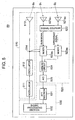
- a monopulse type radar 50 has a transmitting section 510 which sends a mm-Wave B 0 to ahead of the loaded vehicle, a receiving section 520 which receives at mutually different positions echoes B 1 , B 2 from the target, a control processing section 530 which detects target information (the presence of a target, a distance from the target, a relative speed of the target and an azimuth angle in a horizontal plane of the target) and a housing (not shown) for enclosing them.
- target information the presence of a target, a distance from the target, a relative speed of the target and an azimuth angle in a horizontal plane of the target
- the transmitting section 510 includes a modulator 511 which alternately outputs two kinds of modulated signals according to a changing command from the control processing section 530, an oscillator 512 which outputs a high-frequency signal (e.g., a millimeter wave) having a transmission frequency corresponding to the modulated signal from the modulator 511, a transmitting antenna 513 which radiates the output signal from the oscillator 512 as the mm-Wave B 0 , a directional coupler 514 which guides part of the output, which is from the oscillator 512 as a reference signal for the conversion of a frequency into an intermediate frequency band, to the receiving section 520, and the like.
- the transmitting section 510 alternately emits continuous waves with mutually different transmission frequencies f 1 , f 2 from the transmitting antenna 513 to ahead of the loaded vehicle as shown in Fig. 6.
- a distance from a preceding vehicle is shorter than when traveling at a high speed, so that the vehicles tend to have a short distance between them.
- the radar is aimed at a driver's watching area when traveling at a high speed, the emitted electric field becomes narrow at a short distance as shown in Fig. 7.
- the target is closest to the own vehicle M and close to a line
- a field-of-view ⁇ of the mm-Wave B 0 from the transmitting antenna 513 is expanded to include at least a prescribed portion of the target, which is closest to the own vehicle M and close to a line, into the electric field emitted from the transmitting antenna 513.
- the assumed closest distance to the target is not a minimum distance that two vehicles can be approached physically but a designed minimum distance that the own vehicle can approach the preceding vehicle while securing traveling safety, specifically a distance that is assumed to be kept from the preceding vehicle when a traffic is heavy. Its specific value is variable depending on vehicle types on which the radar device is mounted but generally approximately 1 m to 3 m.
- the reason of determining the field-of-view ⁇ so to include at least a certain portion present in the closest distance from the own vehicle M in the emitted electric field is that an error ⁇ L is caused between a vehicle-to-vehicle distance L 2 'detected by the radar 50 and a real vehicle-to-vehicle distance L 1 if the tail end of the preceding vehicle T which is present in the same traveling lane as the own vehicle M and close to a line, namely a portion in the closest distance from the own vehicle M, is not included in the emitted electric field as shown in Fig. 8.
- the field-of-view ⁇ of the mm-Wave B 0 from the transmitting antenna 513 is determined so that the emitted electric field includes an area T 0 including a position which is ahead by a distance Lmin corresponding to the minimum vehicle-to-vehicle distance when the own vehicle M becomes closest to the immediately preceding vehicle T while keeping safety and displaced by a distance corresponding to a half Wv/2 of a vehicle width Wv from the central axis m of the own vehicle M is included in the emitted electric field.
- a horizontal width ⁇ W of the area T 0 may be determined according to a horizontal resolution. As shown in Fig.
- the field-of-view ⁇ of the mm-Wave B 0 from the transmitting antenna 513 is determined so that the emitted electric field includes the area T 0 including a position which is ahead by a distance Lmin corresponding to the vehicle-to-vehicle distance when the own vehicle becomes closest to the immediately preceding vehicle T while keeping safety and displaced by a distance corresponding to the sum (Wv/2+ ⁇ C) of a half Wv/2 of the vehicle width Wv and an offset amount ⁇ C of the central axis b of the mm-Wave B 0 .
- the horizontal width ⁇ W of the area T 0 may be determined according to the horizontal resolution.
- the receiving section 520 has a hybrid circuit 522 which generates a sum signal of output signals from two receiving antennas 521a 1 , 521a 2 located at different positions and directed in the same direction as the central axis of the mm-Wave B 0 for the individual transmission frequencies f 1 , f 2 and also generates a difference signal of the output signals from the two receiving antennas 521a 1 , 521a 2 for one (e.g., f 1 ) of the transmission frequencies, two mixers 523a 1 , 523a 2 which generate a beat signal by mixing each of output signals from the hybrid circuit 522 and a signal from the directional coupler 514, an analog circuit 525 which demodulates and amplifies a beat signal from each of the mixers 523a 1 , 523a 2 for each of the transmission frequencies f 1 , f 2 , an A/D converter 524 which samples an analog signal output for each of the transmission frequencies f 1 , f 2 from the analog circuit 525 at appropriate sampling intervals
- the two receiving antennas 521a 1 , 521a 2 of the receiving section 520 are disposed to form a line in a horizontal direction together with the transmitting antenna 513 of the transmitting section 510 as shown in Fig. 11.
- Total length W of the arrangement of these three antennas 513, 521a 1 , 521a 2 has a relationship indicated by the expression below between a wavelength ⁇ and the field-of-view ⁇ of the mm-Wave B 0 from the transmitting antenna 513 as shown in Fig. 12.
- the total length W of the arrangement of the three antennas 513, 521a 1 , 521a 2 is inversely proportional to the field-of-view ⁇ of the mm-Wave B 0 from the transmitting antenna 513. Therefore, when the field-of-view ⁇ of the mm-Wave B 0 from the transmitting antenna 513 is expanded, the total length W of the arrangement of the three antennas 513, 521a 1 , 521a 2 becomes short, and the overall size of the radar device can be made compact.
- the field-of-view ⁇ of the mm-Wave B 0 from the transmitting antenna 513 is expanded to a level capable of detecting the vehicle which is in the shortest vehicle-to-vehicle distance when traveling at a low speed and close to a line in this embodiment, so that a compact radar device can be realized.
- the radar device which can be used in either traveling condition of high-speed running or low-speed running, can be realized as compact one suitable for accommodation according to this embodiment.
- the control section 530 has a digital signal processor which is connected to equipment (such as an output device to be described later) which uses the calculated result.
- This digital signal processor realizes a functional configuration section such as an FFT (FFT: Fast Fourier Transform) section 531, a signal processing section 532, and the like.
- FFT Fast Fourier Transform
- the FFT section 531 decomposes the sampled signal from the A/D converter 524 into frequency components to output an amplitude, a frequency and a phase of the peak of the obtained frequency spectrum.
- the signal processing section 532 instructs timing of switching two transmission frequencies f 1 , f 2 to the modulator 511, calculates based on the output from the FFT section 531 as shown below and outputs the calculated result as target information.
- the signal processing section 532 calculates a relative speed of the target and a distance to the target based on the frequency and phase of the peak of the frequency spectrum obtained from the sum signal of the respective transmission frequencies f 1 , f 2 and outputs the calculated results as target information indicating the relative speed of the target and the distance to the target. And, the signal processing section 532 calculates an amplitude ratio (difference signal/sum signal) of the peak of the frequency spectra obtained from one sum signal and a difference signal of the same transmission frequency f 1 as that in the output from the FFT section 531. As shown in Fig.
- the signal processing section 532 outputs the calculated amplitude ratio as target information indicating the azimuth angle ⁇ of the target with respect to the reference direction.
- the signal processing section 532 also outputs the peak amplitude which is output from the FFT section 531 as target information indicating the presence or not of the target.
- this vehicle running support system includes the above-described radar device 50 for detecting target information F, a vehicle speed sensor (not shown) for detecting a running speed V M of the own vehicle M, a vehicle-to-vehicle distance control device 60 for outputting a control command based on the output F of the radar device 50 and the output V M of the vehicle speed sensor, a throttle control device 63 for controlling a throttle opening of the own vehicle M according to the control command from the vehicle-to-vehicle distance control device 60, a transmission control device 62 for controlling the transmission of the own vehicle M according to the control command from the vehicle-to-vehicle distance control device 60, a brake control device 61 for controlling the brakes of the own vehicle M according to the control command from the vehicle-to-vehicle distance control device 60, a warning device 65 for outputting a warning by voice or the like, a warning control device 64 for controlling the warning device 65 according to the control command from the vehicle-to-vehicle distance control device 60,
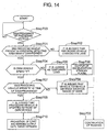
- the vehicle-to-vehicle distance control device 60 when the own vehicle M is running at a low speed, the vehicle-to-vehicle distance control device 60 repeatedly performs the control processing shown in Fig. 14 based on the output F of the radar device 50 and output V of the vehicle speed sensor. Specifically, it is performed as follows.
- the vehicle-to-vehicle distance control device 60 monitors a distance to the preceding vehicle T in the target information F sequentially output by the radar device 50 to sequentially judge whether or not the preceding vehicle T is present within a prescribed distance from the own vehicle M. If the preceding vehicle T is found within a prescribed distance from the own vehicle M, the vehicle-to-vehicle distance control device 60 monitors a level of the signal indicating the presence or not of the preceding vehicle T in the target information F (Step 700).
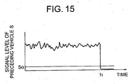
- the vehicle-to-vehicle distance control device 60 judges that the echo from the preceding vehicle T has disappeared and also judges whether or not the preceding vehicle T is present within an electric field emitted from the transmitting antenna 513 at the time of disappearance t 1 of the echo.
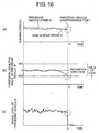
- the vehicle-to-vehicle distance control device 60 judges that the preceding vehicle T has moved out of the running lane of the own vehicle M because the preceding vehicle T or the own vehicle M has changed its lane (Step 702) and gives a control command for making to keep the running speed V M of the own vehicle M to the throttle control device 63 at the time of echo disappearance t 1 shown in Fig. 16(A) (Step 703).
- the vehicle-to-vehicle control device 60 judges whether or not the own vehicle M is running or not at the time of echo disappearance t 1 . Specifically, when the output V M of the vehicle speed sensor has the threshold value V 0 or more at the time of echo disappearance t 1 , it is judged that the own vehicle M was running at the time of echo disappearance t 1 , and when the output is other than what was described above, it is judged that the own vehicle M was stopped at the time of echo disappearance t 1 (Step 704).
- the vehicle-to-vehicle distance control device 60 judges that the target present in the electric field emitted from the transmitting antenna 513 is temporarily lost (Step 705) and gives a deceleration command to the throttle control device 63 and the transmission control device 62 and also a warning output command to the warning control device 64 (Step 706).
- the own vehicle M decelerates when issuing a warning from the warning device 65.
- the vehicle-to-vehicle distance control device 60 judges whether or not the preceding vehicle T was running at the time of echo disappearance t 1 . Specifically, a running speed V T of the preceding vehicle T at the time of echo disappearance t 1 is calculated by subtracting the output V M of the vehicle speed sensor at the time of echo disappearance t 1 from a relative speed of the preceding vehicle T at the time of echo disappearance t 1 .
- the calculated value is a threshold value V 0 or more, it is judged that the preceding vehicle T was running at the time of echo disappearance t 1 , and when it is other than what was described above, it is judged that the preceding vehicle T was stopped at the time of echo disappearance t 1 (Step 707).
- the vehicle-to-vehicle distance control device 60 judges that the distance between the own vehicle M and the preceding vehicle T has increased to a reached distance or more of the mm-Waves B 0 and gives a control command for making to keep the running speed V M of the own vehicle M at the time of echo disappearance t 1 to the throttle control device 63 (Step 703). And, when it is judged that the preceding vehicle T was stopped at the time of echo disappearance t 1 , both the preceding vehicle T and the own vehicle M were stopped at the time of echo disappearance t 1 as shown in Figs.
- Step 709 gives a warning output command to the warning control device 64 and prohibits the own vehicle M from starting to move until a signal level S of the radar output indicating the presence or not of the preceding vehicle T exceeds the threshold value S 0 again (Step 710).
- the own vehicle M keeps the stopped state until the preceding vehicle T starts to move again after the warning device 65 issues a warning.
- the radar device 50 can detect even a preceding vehicle, which is most approached and close to a line when traveling at a low speed, without fail as described above. Therefore, the above-described control processing can be performed based on the output of the radar device 50 to enhance traveling safety when the own vehicle has become closer to the preceding vehicle when traveling at a low speed.
- preceding vehicles T which come closer to the own vehicle M when running at a low speed include big trucks having a large height.
- a rotating shaft for holding the radar device 50 to be vertically rotatable and a servomotor for rotating the radar device 50 about the rotating shaft are additionally disposed to prevent the mm-Wave B 0 from the radar device 50 from passing through when the own vehicle comes closer to a preceding vehicle having a large height.
- the vehicle-to-vehicle distance control device 60 controls the servomotor to turn upward the radar device 50 as shown in Fig. 18(B).
- the mm-Wave B 0 from the radar device 50 is directed upward, so that the tail end of the preceding vehicle T having a large height which is close to the own vehicle M can be detected.
- the radar device 50 may be turned so that an elevation angle ⁇ of the radar device 50 is changed from zero degree to a prescribed angle ⁇ 0 as shown in Fig. 19, or the elevation angle ⁇ of the radar device 50 may be increased gradually from zero degree to the prescribed angle ⁇ 0 as the distance to the preceding vehicle T decreases as shown in Fig. 20.
- the vehicle-to-vehicle distance control device 60 controls the servomotor to turn the radar device 50 downward as shown in Fig. 18(C).
- the mm-Wave B 0 from the radar device 50 returns to the horizontal state, so that it becomes possible to detect the tail end of the preceding vehicle T having a large height that is getting away from the own vehicle.
- the radar device 50 may be turned to change the elevation angle ⁇ of the radar device 50 from the prescribed angle ⁇ 0 to zero degree or the elevation angle ⁇ of the radar device 50 may be increased gradually from the prescribed angle ⁇ 0 to zero degree as the distance from the preceding vehicle T increases.
- the preceding vehicle having a large height can also be detected by controlling the elevation angle ⁇ of the radar device 50.
- a beat signal obtained by mixing the transmitted mm-Wave and the echo from the target is subjected to the FFT processing, and a distance to the target and a relative speed of the target are obtained from the peaks of the frequency spectrum obtained as a result as shown in Figs. 21(B), (C).
- a radar of a type other than the dual-frequency CW system to which the present invention is applied is adopted as a radar device of the running support system shown in Fig. 13, it is necessary to appropriately change the control processing to be performed by the vehicle-to-vehicle distance control device depending on the output of the radar.
- the FMCW radar to which the present invention is applied is adopted, a signal indicating the presence.of the preceding vehicle is lost if both the own vehicle and the preceding vehicle stop. Therefore, a control processing different from the above-described control processing of the running support system adopting the dual-frequency CW radar is carried out.
- the vehicle-to-vehicle distance control device monitors a relative speed of the preceding vehicle which is present at a prescribed distance from the own vehicle and a running speed of the own vehicle and both of them have a threshold value V 0 or below, it is judged that the preceding vehicle is stopped in front of the stopped own vehicle. Then, a warning output command is given to the warning control device 64, and it may be configured to prohibit the own vehicle from starting to move until the relative speed of the preceding vehicle present at a prescribed distance from the own vehicle exceeds the threshold value V 0 again. Besides, in addition to the above control processing, it is desirable to perform the processing excluding Step 709 and Step 710 in the processing contained in Step 704 in the control processing shown in Fig.
- Step 14 by the vehicle-to-vehicle distance control device.
- it may be configured to judge in Step 704 that a relative speed of the preceding vehicle is not higher than the threshold value V 0 , to perform Step 705 and Step 706 when the relative speed of the preceding vehicle is not higher than the threshold value V 0 , and to perform Step 708 and Step 703 when the relative speed of the preceding vehicle exceeds the threshold value V 0 .
- traveling safety of a vehicle running at a low speed, which has come closer to a preceding vehicle can be enhanced furthermore.
Landscapes
- Engineering & Computer Science (AREA)
- Radar, Positioning & Navigation (AREA)
- Remote Sensing (AREA)
- Physics & Mathematics (AREA)
- Computer Networks & Wireless Communication (AREA)
- General Physics & Mathematics (AREA)
- Electromagnetism (AREA)
- Radar Systems Or Details Thereof (AREA)
Abstract
Description
Claims (6)
- A radar device which is mounted on a vehicle body and detects a target present in a moving direction of the vehicle body, comprising:a transmitting antenna for transmitting a mm-Wave that forms an electric field having a width determined according to a width of the vehicle body at a position away from the vehicle body in a moving direction of the vehicle body by a distance corresponding to a most-approached distance prescribed between the vehicle body and the target; andtwo receiving antennas for receiving reflected mm-Waves at mutually different positions.
- The radar device according to Claim 1, wherein:when a central axis of the mm-Wave and a central axis of the vehicle body are deviated from each other, the.transmitting antenna transmits the mm-Wave that forms an electric field having a width determined according to a space between the central axis of the mm-Wave and the central axis of the vehicle body and a width of the vehicle body at a position away in a moving direction of the vehicle body by a distance corresponding to a most-approached distance.
- The radar device according to Claim 1, wherein:the transmitting antenna alternately transmits as the mm-Wave two kinds of continuous waves having mutually different transmission frequencies.
- A system for assisting running of a vehicle, comprising:a radar device for detecting a distance from the vehicle to a target;a rotating shaft for holding the radar device to be turnable in a vertical direction of the vehicle in a running condition;a motor for turning the radar device; anda control device for controlling a turning angle of the motor according to a distance detected by the radar device.
- A system for assisting running of a vehicle, comprising:the radar device according to Claim 3; anda control device which does not output a start command of the vehicle until the output of the radar device is resumed after an output of the radar device is interrupted.
- A system for assisting running of a vehicle, comprising:the radar device according to Claim 1 or 2; anda warning device for outputting a warning when it becomes impossible to detect a target after the radar device detects the target at a position away in a moving direction of the vehicle body by a distance corresponding to a most-approached distance.
Applications Claiming Priority (1)
| Application Number | Priority Date | Filing Date | Title |
|---|---|---|---|
| PCT/JP2001/004540 WO2002099456A1 (en) | 2001-05-30 | 2001-05-30 | Radar device |
Publications (2)
| Publication Number | Publication Date |
|---|---|
| EP1391748A1 true EP1391748A1 (en) | 2004-02-25 |
| EP1391748A4 EP1391748A4 (en) | 2007-01-31 |
Family
ID=11737370
Family Applications (1)
| Application Number | Title | Priority Date | Filing Date |
|---|---|---|---|
| EP01936817A Withdrawn EP1391748A4 (en) | 2001-05-30 | 2001-05-30 | Radar device |
Country Status (4)
| Country | Link |
|---|---|
| US (1) | US7570197B2 (en) |
| EP (1) | EP1391748A4 (en) |
| JP (1) | JP4088583B2 (en) |
| WO (1) | WO2002099456A1 (en) |
Cited By (7)
| Publication number | Priority date | Publication date | Assignee | Title |
|---|---|---|---|---|
| EP1684092A1 (en) * | 2005-01-20 | 2006-07-26 | Hitachi, Ltd. | Automotive radar with mechanically scanned monopulse antenna |
| EP2068172A2 (en) | 2007-12-04 | 2009-06-10 | Robert Bosch GmbH | Adaptive nulling in monopulse difference antenna diagram to improve the angular resolution at object locations |
| EP2073034A3 (en) * | 2007-12-22 | 2010-03-24 | Audi AG | Motor vehicle with a combination of forward-looking radars with overlapping beams |
| EP2172788A1 (en) * | 2008-10-03 | 2010-04-07 | Honeywell International Inc. | Radar system for obstacle avoidance |
| DE102008052246A1 (en) * | 2008-10-18 | 2010-04-22 | Adc Automotive Distance Control Systems Gmbh | Beam sensor system e.g. radio detection and ranging system, for driver assistance system of motor vehicle, has signal processing units processing received signals, where system evaluates intensity of received reflections of objects |
| US7898462B2 (en) | 2008-10-03 | 2011-03-01 | Honeywell International Inc. | Multi-sector radar sensor |
| US8477063B2 (en) | 2008-10-03 | 2013-07-02 | Honeywell International Inc. | System and method for obstacle detection and warning |
Families Citing this family (18)
| Publication number | Priority date | Publication date | Assignee | Title |
|---|---|---|---|---|
| JP2005156337A (en) * | 2003-11-26 | 2005-06-16 | Hitachi Ltd | Automotive radar equipment |
| DE102004019651A1 (en) * | 2004-04-22 | 2005-11-17 | Siemens Ag | Blind spot sensor system |
| US20060089759A1 (en) * | 2004-10-22 | 2006-04-27 | Honeywell International Inc. | Systems and methods for performing high accurate distance measuring for radar altimeters |
| JP2006163609A (en) * | 2004-12-03 | 2006-06-22 | Nissan Motor Co Ltd | Luminescent sign system and wireless power transmission device |
| JP4304517B2 (en) * | 2005-11-09 | 2009-07-29 | トヨタ自動車株式会社 | Object detection device |
| JP5590777B2 (en) * | 2008-05-12 | 2014-09-17 | トヨタ自動車株式会社 | Radar equipment |
| DE102008054624A1 (en) * | 2008-12-15 | 2010-06-17 | Robert Bosch Gmbh | FMCW radar sensor for motor vehicles |
| WO2011139408A1 (en) * | 2010-05-04 | 2011-11-10 | Raytheon Company | Multistatic target detection and geolocation |
| US8441394B2 (en) * | 2011-07-11 | 2013-05-14 | Delphi Technologies, Inc. | System and method for detecting obstructions and misalignment of ground vehicle radar systems |
| WO2014038076A1 (en) * | 2012-09-07 | 2014-03-13 | トヨタ自動車株式会社 | Vehicle distance control device |
| JP5983572B2 (en) * | 2013-09-20 | 2016-08-31 | 株式会社デンソー | Undercover detection device |
| US9759807B2 (en) * | 2013-10-25 | 2017-09-12 | Texas Instruments Incorporated | Techniques for angle resolution in radar |
| WO2015060997A1 (en) * | 2013-10-25 | 2015-04-30 | Texas Instruments Incorporated | Angle resolution in radar |
| EP3311192A1 (en) * | 2015-06-17 | 2018-04-25 | Novelic D.O.O. | Millimeter-wave sensor system for parking assistance |
| US11696216B2 (en) | 2016-02-18 | 2023-07-04 | Comcast Cable Communications, Llc | SSID broadcast management to support priority of broadcast |
| WO2018186663A1 (en) * | 2017-04-04 | 2018-10-11 | 엘지전자 주식회사 | Method for measuring distance in wireless communication system and device therefor |
| CN109143187A (en) * | 2018-09-29 | 2019-01-04 | 惠州市德赛西威汽车电子股份有限公司 | A kind of vehicle-mounted millimeter wave angle radar test method |
| FR3126788B1 (en) * | 2021-09-03 | 2023-10-13 | Cie Plastic Omnium Se | Radar system, body part and associated vehicle |
Family Cites Families (40)
| Publication number | Priority date | Publication date | Assignee | Title |
|---|---|---|---|---|
| US2690555A (en) * | 1947-10-10 | 1954-09-28 | James Lewis Bradley | Protection system for mobile bodies |
| US3778823A (en) * | 1970-12-27 | 1973-12-11 | Toyota Motor Co Ltd | Vehicle safety device |
| US3749197A (en) * | 1971-05-12 | 1973-07-31 | B Deutsch | Obstacle detection system |
| US3735398A (en) * | 1971-05-20 | 1973-05-22 | Sperry Rand Corp | Base band short range pre-collision sensor for actuation of vehicle safety apparatus |
| US3772690A (en) * | 1971-12-07 | 1973-11-13 | Sperry Rand Corp | Vehicle safety apparatus |
| US3750169A (en) * | 1972-03-13 | 1973-07-31 | Sperry Rand Corp | Vehicular safety system |
| US3858205A (en) * | 1972-10-06 | 1974-12-31 | Sperry Rand Corp | Base-band precollision sensor with time domain gating for preventing false responses |
| US4150375A (en) * | 1978-03-02 | 1979-04-17 | Sperry Rand Corporation | Interferometric protective system for vehicles |
| US5023617A (en) * | 1990-02-20 | 1991-06-11 | General Motors Corporation | Vehicle forward sensor antenna steering system |
| JP3007213B2 (en) | 1992-02-18 | 2000-02-07 | 日本無線株式会社 | Automotive radar equipment |
| JPH06160518A (en) * | 1992-11-18 | 1994-06-07 | Mitsubishi Electric Corp | Automotive radar device |
| JP2953232B2 (en) * | 1993-01-19 | 1999-09-27 | トヨタ自動車株式会社 | Frequency modulation radar equipment |
| US5402129A (en) * | 1993-08-04 | 1995-03-28 | Vorad Safety Systems, Inc. | Monopulse azimuth radar system for automotive vehicle tracking |
| JPH07128443A (en) * | 1993-11-02 | 1995-05-19 | Toyota Motor Corp | In-vehicle radar device |
| JP3147675B2 (en) | 1994-09-16 | 2001-03-19 | 日産自動車株式会社 | Radar equipment for vehicles |
| JP3302849B2 (en) * | 1994-11-28 | 2002-07-15 | 本田技研工業株式会社 | Automotive radar module |
| JP3498434B2 (en) | 1995-07-25 | 2004-02-16 | 株式会社デンソー | Aperture antenna, antenna driving circuit, and radar device |
| DE69611278T2 (en) | 1995-11-10 | 2001-05-23 | Toyota Jidosha K.K., Toyota | Radar device for detecting the direction of the center of a target |
| GB9602250D0 (en) * | 1996-02-05 | 1996-04-03 | Secr Defence | Collision warning system |
| JP3314623B2 (en) * | 1996-08-12 | 2002-08-12 | トヨタ自動車株式会社 | In-vehicle scanning radar |
| US6087975A (en) * | 1997-06-25 | 2000-07-11 | Honda Giken Kogyo Kabushiki Kaisha | Object detecting system for vehicle |
| JPH1138121A (en) * | 1997-07-15 | 1999-02-12 | Mitsubishi Electric Corp | Automotive radar equipment |
| JP3414267B2 (en) | 1997-07-22 | 2003-06-09 | 株式会社デンソー | Central axis deflection amount calculation device, center axis deflection amount correction device, and inter-vehicle distance control device of vehicle obstacle detection device |
| JP3580094B2 (en) * | 1997-08-28 | 2004-10-20 | 日産自動車株式会社 | Forward recognition device |
| JP3475745B2 (en) | 1997-10-09 | 2003-12-08 | 日産自動車株式会社 | Inter-vehicle distance alarm |
| JPH11144198A (en) * | 1997-11-14 | 1999-05-28 | Mazda Motor Corp | Vehicle object identification device |
| JP3462740B2 (en) | 1998-01-06 | 2003-11-05 | 株式会社日立製作所 | Axis adjustment method for automotive radar |
| JP3395623B2 (en) | 1998-01-19 | 2003-04-14 | 株式会社日立製作所 | Vehicle travel control device |
| JPH11326495A (en) * | 1998-05-13 | 1999-11-26 | Hitachi Ltd | Antenna axis adjustment device for automotive radar |
| JP2000230974A (en) * | 1999-02-09 | 2000-08-22 | Toyota Motor Corp | Radar equipment |
| JP3622565B2 (en) * | 1999-03-31 | 2005-02-23 | 株式会社デンソー | Radar equipment |
| JP2000292530A (en) * | 1999-04-09 | 2000-10-20 | Hino Motors Ltd | Radar equipment |
| JP3514166B2 (en) | 1999-05-06 | 2004-03-31 | 日産自動車株式会社 | Preceding vehicle recognition device |
| JP4258941B2 (en) | 1999-06-03 | 2009-04-30 | 株式会社デンソー | Radar equipment |
| JP3411866B2 (en) * | 1999-10-25 | 2003-06-03 | 株式会社日立製作所 | Millimeter wave radar device |
| JP4134462B2 (en) | 1999-10-28 | 2008-08-20 | 株式会社デンソー | Radar device, adjustment method, adjustment system |
| US6573859B2 (en) * | 2000-02-07 | 2003-06-03 | Toyota Jidosha Kabushiki Kaisha | Radar apparatus |
| DE10005558A1 (en) * | 2000-02-09 | 2001-08-23 | Bosch Gmbh Robert | Vehicle data communications device uses dual channel communications microwave frequencies for intermediate frequency processing by conventional parts |
| JP3988571B2 (en) * | 2001-09-17 | 2007-10-10 | 株式会社デンソー | Radar equipment |
| US6583753B1 (en) * | 2002-04-03 | 2003-06-24 | Delphi Technologies, Inc. | Vehicle back-up and parking aid radar system |
-
2001
- 2001-05-30 EP EP01936817A patent/EP1391748A4/en not_active Withdrawn
- 2001-05-30 US US10/478,805 patent/US7570197B2/en not_active Expired - Fee Related
- 2001-05-30 JP JP2003502521A patent/JP4088583B2/en not_active Expired - Fee Related
- 2001-05-30 WO PCT/JP2001/004540 patent/WO2002099456A1/en not_active Ceased
Cited By (10)
| Publication number | Priority date | Publication date | Assignee | Title |
|---|---|---|---|---|
| EP1684092A1 (en) * | 2005-01-20 | 2006-07-26 | Hitachi, Ltd. | Automotive radar with mechanically scanned monopulse antenna |
| EP2068172A2 (en) | 2007-12-04 | 2009-06-10 | Robert Bosch GmbH | Adaptive nulling in monopulse difference antenna diagram to improve the angular resolution at object locations |
| EP2068172A3 (en) * | 2007-12-04 | 2010-03-24 | Robert Bosch GmbH | Adaptive nulling in monopulse difference antenna diagram to improve the angular resolution at object locations |
| US8035548B2 (en) | 2007-12-04 | 2011-10-11 | Robert Bosch Gmbh | Evaluation method, particularly for a driver assistance system of a motor vehicle, for object detection using a radar sensor |
| EP2073034A3 (en) * | 2007-12-22 | 2010-03-24 | Audi AG | Motor vehicle with a combination of forward-looking radars with overlapping beams |
| EP2172788A1 (en) * | 2008-10-03 | 2010-04-07 | Honeywell International Inc. | Radar system for obstacle avoidance |
| US7868817B2 (en) | 2008-10-03 | 2011-01-11 | Honeywell International Inc. | Radar system for obstacle avoidance |
| US7898462B2 (en) | 2008-10-03 | 2011-03-01 | Honeywell International Inc. | Multi-sector radar sensor |
| US8477063B2 (en) | 2008-10-03 | 2013-07-02 | Honeywell International Inc. | System and method for obstacle detection and warning |
| DE102008052246A1 (en) * | 2008-10-18 | 2010-04-22 | Adc Automotive Distance Control Systems Gmbh | Beam sensor system e.g. radio detection and ranging system, for driver assistance system of motor vehicle, has signal processing units processing received signals, where system evaluates intensity of received reflections of objects |
Also Published As
| Publication number | Publication date |
|---|---|
| WO2002099456A1 (en) | 2002-12-12 |
| US7570197B2 (en) | 2009-08-04 |
| EP1391748A4 (en) | 2007-01-31 |
| JPWO2002099456A1 (en) | 2004-09-16 |
| US20040145512A1 (en) | 2004-07-29 |
| JP4088583B2 (en) | 2008-05-21 |
Similar Documents
| Publication | Publication Date | Title |
|---|---|---|
| US7570197B2 (en) | Radar device | |
| US7504989B2 (en) | On-vehicle radar device | |
| JP4007498B2 (en) | Automotive radar equipment | |
| EP1548458A2 (en) | Vehicle-mounted radar | |
| US7924215B2 (en) | Radar apparatus and mobile object | |
| JP4093109B2 (en) | Radar equipment for vehicles | |
| US9435883B2 (en) | Antenna, radar apparatus and signal processing method | |
| US9310470B2 (en) | Radar apparatus and signal processing method | |
| US7786926B2 (en) | Radar system for motor vehicles | |
| JP3398745B2 (en) | Automotive radar equipment | |
| EP1385020B1 (en) | Fm-cw radar apparatus | |
| US20110084872A1 (en) | Signal processing apparatus and radar apparatus | |
| JP2003315452A (en) | Radar equipment | |
| JP2001242242A (en) | Millimeter wave radar device with detection performance improvement function | |
| US6943727B2 (en) | Length measurement with radar | |
| CN113678017A (en) | Electronic device, control method of electronic device, and control program of electronic device | |
| JP3733914B2 (en) | Vehicle object detection device, vehicle safety control method, automobile | |
| CN112789517A (en) | Electronic device, control method for electronic device, and control program for electronic device | |
| JPH1138121A (en) | Automotive radar equipment | |
| JP2009058316A (en) | Radar device, object detection method, and vehicle | |
| WO2005066656A1 (en) | Vehicle mounted radar system and its signal processing method | |
| US7091900B2 (en) | Radar | |
| JP4446931B2 (en) | Radar equipment | |
| JP2006058135A (en) | Moving object detection apparatus and moving object detection method | |
| JP3577237B2 (en) | Radar equipment for vehicles |
Legal Events
| Date | Code | Title | Description |
|---|---|---|---|
| PUAI | Public reference made under article 153(3) epc to a published international application that has entered the european phase |
Free format text: ORIGINAL CODE: 0009012 |
|
| 17P | Request for examination filed |
Effective date: 20031212 |
|
| AK | Designated contracting states |
Kind code of ref document: A1 Designated state(s): AT BE CH CY DE DK ES FI FR GB GR IE IT LI LU MC NL PT SE TR |
|
| A4 | Supplementary search report drawn up and despatched |
Effective date: 20070102 |
|
| 17Q | First examination report despatched |
Effective date: 20070326 |
|
| GRAP | Despatch of communication of intention to grant a patent |
Free format text: ORIGINAL CODE: EPIDOSNIGR1 |
|
| RIC1 | Information provided on ipc code assigned before grant |
Ipc: G01S 13/93 20060101ALI20120402BHEP Ipc: G01S 13/48 20060101ALI20120402BHEP Ipc: G01S 13/42 20060101ALI20120402BHEP Ipc: G01S 13/34 20060101AFI20120402BHEP Ipc: G01S 13/44 20060101ALI20120402BHEP |
|
| STAA | Information on the status of an ep patent application or granted ep patent |
Free format text: STATUS: THE APPLICATION IS DEEMED TO BE WITHDRAWN |
|
| 18D | Application deemed to be withdrawn |
Effective date: 20120914 |