EP2068172A2 - Adaptive nulling in monopulse difference antenna diagram to improve the angular resolution at object locations - Google Patents
Adaptive nulling in monopulse difference antenna diagram to improve the angular resolution at object locations Download PDFInfo
- Publication number
- EP2068172A2 EP2068172A2 EP08105549A EP08105549A EP2068172A2 EP 2068172 A2 EP2068172 A2 EP 2068172A2 EP 08105549 A EP08105549 A EP 08105549A EP 08105549 A EP08105549 A EP 08105549A EP 2068172 A2 EP2068172 A2 EP 2068172A2
- Authority
- EP
- European Patent Office
- Prior art keywords
- motor vehicle
- radar sensor
- radar
- evaluation method
- zero point
- Prior art date
- Legal status (The legal status is an assumption and is not a legal conclusion. Google has not performed a legal analysis and makes no representation as to the accuracy of the status listed.)
- Ceased
Links
Images

Classifications
-
- G—PHYSICS
- G01—MEASURING; TESTING
- G01S—RADIO DIRECTION-FINDING; RADIO NAVIGATION; DETERMINING DISTANCE OR VELOCITY BY USE OF RADIO WAVES; LOCATING OR PRESENCE-DETECTING BY USE OF THE REFLECTION OR RERADIATION OF RADIO WAVES; ANALOGOUS ARRANGEMENTS USING OTHER WAVES
- G01S13/00—Systems using the reflection or reradiation of radio waves, e.g. radar systems; Analogous systems using reflection or reradiation of waves whose nature or wavelength is irrelevant or unspecified
- G01S13/88—Radar or analogous systems specially adapted for specific applications
- G01S13/93—Radar or analogous systems specially adapted for specific applications for anti-collision purposes
- G01S13/931—Radar or analogous systems specially adapted for specific applications for anti-collision purposes of land vehicles
-
- G—PHYSICS
- G01—MEASURING; TESTING
- G01S—RADIO DIRECTION-FINDING; RADIO NAVIGATION; DETERMINING DISTANCE OR VELOCITY BY USE OF RADIO WAVES; LOCATING OR PRESENCE-DETECTING BY USE OF THE REFLECTION OR RERADIATION OF RADIO WAVES; ANALOGOUS ARRANGEMENTS USING OTHER WAVES
- G01S13/00—Systems using the reflection or reradiation of radio waves, e.g. radar systems; Analogous systems using reflection or reradiation of waves whose nature or wavelength is irrelevant or unspecified
- G01S13/02—Systems using reflection of radio waves, e.g. primary radar systems; Analogous systems
- G01S13/06—Systems determining position data of a target
- G01S13/42—Simultaneous measurement of distance and other co-ordinates
- G01S13/422—Simultaneous measurement of distance and other co-ordinates sequential lobing, e.g. conical scan
-
- G—PHYSICS
- G01—MEASURING; TESTING
- G01S—RADIO DIRECTION-FINDING; RADIO NAVIGATION; DETERMINING DISTANCE OR VELOCITY BY USE OF RADIO WAVES; LOCATING OR PRESENCE-DETECTING BY USE OF THE REFLECTION OR RERADIATION OF RADIO WAVES; ANALOGOUS ARRANGEMENTS USING OTHER WAVES
- G01S13/00—Systems using the reflection or reradiation of radio waves, e.g. radar systems; Analogous systems using reflection or reradiation of waves whose nature or wavelength is irrelevant or unspecified
- G01S13/02—Systems using reflection of radio waves, e.g. primary radar systems; Analogous systems
- G01S13/06—Systems determining position data of a target
- G01S13/42—Simultaneous measurement of distance and other co-ordinates
- G01S13/44—Monopulse radar, i.e. simultaneous lobing
- G01S13/4445—Monopulse radar, i.e. simultaneous lobing amplitude comparisons monopulse, i.e. comparing the echo signals received by an antenna arrangement with overlapping squinted beams
-
- G—PHYSICS
- G01—MEASURING; TESTING
- G01S—RADIO DIRECTION-FINDING; RADIO NAVIGATION; DETERMINING DISTANCE OR VELOCITY BY USE OF RADIO WAVES; LOCATING OR PRESENCE-DETECTING BY USE OF THE REFLECTION OR RERADIATION OF RADIO WAVES; ANALOGOUS ARRANGEMENTS USING OTHER WAVES
- G01S13/00—Systems using the reflection or reradiation of radio waves, e.g. radar systems; Analogous systems using reflection or reradiation of waves whose nature or wavelength is irrelevant or unspecified
- G01S13/66—Radar-tracking systems; Analogous systems
- G01S13/72—Radar-tracking systems; Analogous systems for two-dimensional tracking, e.g. combination of angle and range tracking, track-while-scan radar
- G01S13/723—Radar-tracking systems; Analogous systems for two-dimensional tracking, e.g. combination of angle and range tracking, track-while-scan radar by using numerical data
- G01S13/726—Multiple target tracking
-
- G—PHYSICS
- G01—MEASURING; TESTING
- G01S—RADIO DIRECTION-FINDING; RADIO NAVIGATION; DETERMINING DISTANCE OR VELOCITY BY USE OF RADIO WAVES; LOCATING OR PRESENCE-DETECTING BY USE OF THE REFLECTION OR RERADIATION OF RADIO WAVES; ANALOGOUS ARRANGEMENTS USING OTHER WAVES
- G01S13/00—Systems using the reflection or reradiation of radio waves, e.g. radar systems; Analogous systems using reflection or reradiation of waves whose nature or wavelength is irrelevant or unspecified
- G01S13/88—Radar or analogous systems specially adapted for specific applications
- G01S13/93—Radar or analogous systems specially adapted for specific applications for anti-collision purposes
- G01S13/931—Radar or analogous systems specially adapted for specific applications for anti-collision purposes of land vehicles
- G01S2013/93185—Controlling the brakes
-
- G—PHYSICS
- G01—MEASURING; TESTING
- G01S—RADIO DIRECTION-FINDING; RADIO NAVIGATION; DETERMINING DISTANCE OR VELOCITY BY USE OF RADIO WAVES; LOCATING OR PRESENCE-DETECTING BY USE OF THE REFLECTION OR RERADIATION OF RADIO WAVES; ANALOGOUS ARRANGEMENTS USING OTHER WAVES
- G01S13/00—Systems using the reflection or reradiation of radio waves, e.g. radar systems; Analogous systems using reflection or reradiation of waves whose nature or wavelength is irrelevant or unspecified
- G01S13/88—Radar or analogous systems specially adapted for specific applications
- G01S13/93—Radar or analogous systems specially adapted for specific applications for anti-collision purposes
- G01S13/931—Radar or analogous systems specially adapted for specific applications for anti-collision purposes of land vehicles
- G01S2013/9321—Velocity regulation, e.g. cruise control
-
- G—PHYSICS
- G01—MEASURING; TESTING
- G01S—RADIO DIRECTION-FINDING; RADIO NAVIGATION; DETERMINING DISTANCE OR VELOCITY BY USE OF RADIO WAVES; LOCATING OR PRESENCE-DETECTING BY USE OF THE REFLECTION OR RERADIATION OF RADIO WAVES; ANALOGOUS ARRANGEMENTS USING OTHER WAVES
- G01S13/00—Systems using the reflection or reradiation of radio waves, e.g. radar systems; Analogous systems using reflection or reradiation of waves whose nature or wavelength is irrelevant or unspecified
- G01S13/88—Radar or analogous systems specially adapted for specific applications
- G01S13/93—Radar or analogous systems specially adapted for specific applications for anti-collision purposes
- G01S13/931—Radar or analogous systems specially adapted for specific applications for anti-collision purposes of land vehicles
- G01S2013/9325—Radar or analogous systems specially adapted for specific applications for anti-collision purposes of land vehicles for inter-vehicle distance regulation, e.g. navigating in platoons
Landscapes
- Engineering & Computer Science (AREA)
- Radar, Positioning & Navigation (AREA)
- Remote Sensing (AREA)
- Physics & Mathematics (AREA)
- Computer Networks & Wireless Communication (AREA)
- General Physics & Mathematics (AREA)
- Electromagnetism (AREA)
- Radar Systems Or Details Thereof (AREA)
- Traffic Control Systems (AREA)
Abstract
Description
Die Erfindung betrifft ein Auswerteverfahren, insbesondere für ein Fahrerassistenzsystem eines Kraftfahrzeugs, zur Objektdetektion mittels eines Radarsensors gemäß dem Oberbegriff von Anspruch 1. Die Erfindung betrifft ebenfalls ein Verfahren zur Kollisionsvermeidung für ein Kraftfahrzeug. Des weiteren betrifft die Erfindung ein Computerprogramm, ein Computerprogrammprodukt und eine Vorrichtung, um derartige Verfahren auszuführen bzw. durchzuführen.The invention relates to an evaluation method, in particular for a driver assistance system of a motor vehicle, for object detection by means of a radar sensor according to the preamble of claim 1. The invention also relates to a method for collision avoidance for a motor vehicle. The invention further relates to a computer program, a computer program product and a device for carrying out such methods.
Ein Auswerteverfahren zur Objektdetektion bzw. ein Objektdetektionsystem kann beispielsweise im Rahmen einer adaptiven Fahrgeschwindigkeits- und/oder -abstandsregelung bzw. eines Fahrerassistenzsystems eines Kraftfahrzeugs eingesetzt werden. Eine solche Regelung kann ohne Eingriff durch den Fahrer eine zuvor eingestellte Fahrgeschwindigkeit und/oder einen zuvor eingestellten Abstand zu einem vorausfahrenden Fahrzeug oder zu sich in Fahrtrichtung befindlichen Gegenständen bzw. Zielobjekten regeln. Dies geschieht unter entsprechender Berücksichtigung des Umfelds des Kraftfahrzeugs und gegebenenfalls weiterer Parameter, wie beispielsweise den aktuellen Witterungs- und Sichtbedingungen. Eine derartige Regelung wird auch als adaptive Geschwindigkeitsregelung bzw. ACC (adaptive cruise control)-System bezeichnet. In der Publikation der Robert Bosch GmbH "Adaptive Fahrgeschwindigkeitsregelung ACC, Gelbe Reihe, Ausgabe 2002, Technische Unterrichtung" sind derartige adaptive Geschwindigkeitsregelvorrichtungen beschrieben. Das ACC-System muss insbesondere im Hinblick auf die steigende Verkehrsdichte der heutigen Zeit flexibel genug sein, um auf alle Fahrsituationen geeignet zu reagieren. Dies erfordert wiederum eine entsprechende Objektsdetektionssensorik, um in jeder Fahrsituation die für die Regelung notwendigen Messdaten hinsichtlich erkannter Zielobjekte bzw. Hindernisse zu liefern.An evaluation method for object detection or an object detection system can be used, for example, as part of an adaptive driving speed and / or distance control or a driver assistance system of a motor vehicle. Such a control can regulate a previously set driving speed and / or a previously set distance to a vehicle in front or to objects or target objects located in the direction of travel without intervention by the driver. This takes place with appropriate consideration of the environment of the motor vehicle and possibly other parameters, such as the current weather and visibility conditions. Such a control is also called adaptive cruise control or ACC (a daptive c ruise c ontrol) system, respectively. In the publication of Robert Bosch GmbH "Adaptive cruise control ACC, Yellow Series, Edition 2002, Technical Instruction" such adaptive cruise control devices are described. The ACC system must be flexible enough to respond to all driving situations, especially in view of the increasing traffic density of today. This, in turn, requires a corresponding object detection sensor system in order to be able to control it in every driving situation To provide measurement data regarding detected target objects or obstacles.
Im Rahmen eines Fahrerassistenzsystems für ein Kraftfahrzeug kann auch ein Verfahren zur Kollisionsvermeidung implementiert sein, bei welchem bei wenigstens einem sich während der Fahrt nähernden Hindernis ein Fahrmanöver des Kraftfahrzeugs autonom oder semiautonom durchgeführt oder vorgeschlagen wird. Das wenigstens eine Hindernis wird ebenfalls mittels eines Auswerteverfahrens zur Objektdetektion bzw. eines Objektdetektionssystems erfasst.Within the scope of a driver assistance system for a motor vehicle, a method for collision avoidance may also be implemented in which a driving maneuver of the motor vehicle is autonomously or semi-autonomously performed or proposed in at least one obstacle approaching during the journey. The at least one obstacle is also detected by means of an evaluation method for object detection or an object detection system.
Häufig werden derartige Objektdetektionssysteme oder Abstandssensoren mittels Radarsensoren realisiert. In der
Insbesondere im Hinblick auf den benötigten Bauraum bzw. den zu wählenden Einbauort derartiger Radarsensoren ist es wünschenswert, diese in ihren Abmessungen so klein wie möglich auszuführen. Die dadurch bedingte relativ geringe Apertur, insbesondere der strahlformenden optischen Elemente bzw. des Radarsensors resultiert in einem geringen Winkeltrennvermögen aufgrund der entsprechenden hinsichtlich des Winkelbereichs relativ breiten Radarstrahlkeulen bzw. Beams. Üblich sind Beams mit 6 dB-Breiten mit einem Winkelbereich von deutlich über 5°. Mit bekannten Auswerteverfahren zur Objektdetektion lassen sich beispielsweise Zielobjekte, welche 2° voneinander beabstandet sind, nicht separieren bzw. trennen. Dies könnte aber etwa bei einer sogenannten Gassensituation, insbesondere auf einer mehrspurigen Autobahn oder dergleichen, wichtig sein, falls sich das eigene Fahrzeug auf der mittleren Spur befindet und in Fahrtrichtung vor dem eigenen Fahrzeug sich auf der rechten und der linken Spur ebenfalls Fahrzeuge befinden. Je nach Abstand von den Fremdfahrzeugen kommt es nun vor, dass die einzelnen Radarstrahlkeulen mehrere Fahrspuren abdecken und somit nicht mehr ermittelt werden kann, ob sich die detektierten Zielobjekte auf der rechten und der linken Spur befinden oder ob sich ein weiteres Zielobjekt auf der mittleren Spur, d. h. der Spur, welche von dem eigenen Fahrzeug befahren wird, befindet, da die Zielobjekte zu einem Ziel verschmelzen und bezüglich des Winkels in Einzelmessungen nicht mehr trennbar sind.In particular, with regard to the required installation space or the chosen installation location of such radar sensors, it is desirable to make them as small as possible in their dimensions. The resulting relatively small aperture, in particular of the beam-shaping optical elements or of the radar sensor results in a low angular separation capability due to the corresponding radar beam lobes or beams which are relatively wide with respect to the angular range. Common are beams with 6 dB widths with an angle range of well over 5 °. With known evaluation methods for object detection, for example Target objects, which are 2 ° apart, do not separate or separate. However, this could be important in a so-called lane situation, in particular on a multi-lane motorway or the like, if the own vehicle is on the middle lane and in the direction of travel in front of the own vehicle are also vehicles on the right lane and the left lane. Depending on the distance from the foreign vehicles, it now happens that the individual radar beam lobes cover several lanes and thus can no longer be determined whether the detected target objects are on the right and left lane or whether another target object on the middle lane, ie the lane, which is traveled by the own vehicle, located because the target objects merge into a target and with respect to the angle in individual measurements are no longer separable.
Zum Stand der Technik hinsichtlich Objektdetektionssystemen, insbesondere für ein Kraftfahrzeug, wird auf die
Das erfindungsgemäße Auswerteverfahren, insbesondere für ein Fahrerassistenzsystems eines Kraftfahrzeugs zur Objektdetektion mittels eines Radarsensors, welcher wenigstens zwei separate Radarstrahlkeulen, welche einen abzutastenden Winkelbereich abdecken, zeitlich synchron aussendet und deren jeweilige Zielantworten als Messwerte empfängt, wobei wenigstens zwei Zielantworten (d. h. jeweils eine Zielantwort je Radarstrahlkeule) der wenigstens zwei separaten Radarstrahlkeulen des Radarsensors derart rechnerisch überlagert werden, dass eine synthetische Radarstrahlkeule mit wenigstens einer vorbestimmten Nullstelle in dem abgetasteten Winkelbereich entsteht, ermöglicht in einfacher und vorteilhafter Weise eine deutliche Verbesserung der Auflösung bzw. Winkeltrennung bei der Objektdetektion. Dies kann ohne zusätzlichen Einsatz von Hardware lediglich mittels spezieller Softwareroutinen bzw. einer modifizierten Auswertemethode bei der Objektdetektion mittels des Radarsensors geschehen. Wird z. B. ein entsprechendes Zielobjekt auf der eigenen Spur in einer bestimmten Position, d. h. unter einem bestimmten Winkel detektiert, so kann durch eine entsprechende Überlagerung der Zielantworten aus zwei Beams bzw. separaten Radarstrahlkeulen des Radarsensors ein synthetischer Beam gebildet werden, welcher eine scharfe Nullstelle an der detektierten Position aufweist. Anschließend kann durch Verlegen der Nullstelle auf den gemessenen Winkel überprüft werden, ob nur ein Zielobjekt an dieser Winkelposition oder beispielsweise mehrere Zielobjekte bei versetztem Winkel vorliegen. Liegt tatsächlich nur ein Zielobjekt vor, so muss dessen Pegel sehr stark abnehmen. Ergibt sich das Zielobjekt nun aus einer Überlagerung von zwei Zielobjekten (beispielsweise in 120 m Abstand, je 3 m seitlich versetzt auf den Nebenspuren), so würde die Signalamplitude nur einen kleineren Teil abnehmen und nicht verschwinden. Dadurch ergibt sich eine zusätzliche Information hinsichtlich der Winkelauflösung. Mit Hilfe des Phasengangs zwischen den Beams bzw. Radarstrahlkeulen der Radarsensoren kann ein Filterverhalten mit ausreichend steilen Flanken erreicht werden. Durch die Nullstelle entsteht eine Art Winkel-Notch bzw. ein Winkel-Notch-Filter.The evaluation method according to the invention, in particular for a driver assistance system of a motor vehicle for object detection by means of a radar sensor which temporally synchronously transmits at least two separate radar beam lobes covering an angular range to be scanned and receives their respective target responses as measured values, at least two target responses (ie in each case one target response per radar beam lobe ) of the at least two separate radar beam lobes of the radar sensor are computationally superimposed in such a way that a synthetic radar beam lobe with at least one predetermined zero point arises in the scanned angular range, allows in a simple and advantageous manner a significant improvement of the resolution or angle separation in the object detection. This can be done without the additional use of hardware only by means of special software routines or a modified evaluation method in the object detection done by means of the radar sensor. If z. B. a corresponding target on its own lane in a particular position, ie detected at a certain angle, it can be formed by a corresponding superposition of the target responses of two beams or separate radar beam lobes of the radar sensor, a synthetic beam, which has a sharp zero at the has detected position. Subsequently, by moving the zero point to the measured angle, it is possible to check whether there is only one target object at this angular position or, for example, several target objects with the angle offset. If only one target is present, its level must decrease very much. If the target object now results from a superimposition of two target objects (for example at 120 m distance, 3 m laterally offset on the secondary tracks), the signal amplitude would decrease only a smaller part and not disappear. This results in additional information regarding the angular resolution. With the aid of the phase response between the beams or radar beam lobes of the radar sensors, a filter behavior with sufficiently steep flanks can be achieved. The zero point creates a kind of angle notch or an angle notch filter.
Die rechnerische Überlagerung kann mittels einer komplexen Gewichtung wenigstens einer der wenigstens zwei Zielantworten derart durchgeführt werden, dass sich für ein Zielobjekt, welches an der wenigstens einen vorbestimmten Nullstelle detektiert wurde, die wenigstens zwei Zielantworten zu Null summieren. Unter Berücksichtigung der Verhältnisse zwischen den Radarstrahlkeulen bzw. Beams gemäß einer Referenzmessung wird nun einer der Beams mit dem Betragsquotienten zu einem weiteren Beam an der Stelle, an der die Nullstelle entstehen soll, multipliziert und durch Phasendrehung, welche den Phasenunterschied an der für die Nullstelle gewünschten Winkelposition zwischen den beiden Beams egalisiert (d. h. hinsichtlich des Pegels gleich jedoch mit einem Phasenunterschied von 180°), modifiziert und von dem weiteren Beam subtrahiert.The computational overlay can be performed by means of a complex weighting of at least one of the at least two target responses such that for a target object which was detected at the at least one predetermined zero, the at least two target responses sum to zero. Taking into account the relationships between the radar beam beams or beams according to a reference measurement, one of the beams with the absolute value quotient is then multiplied by another beam at the point where the zero point is to be formed and by phase rotation, which the phase difference at the desired for the zero point Angular position between the two beams equalized (ie equal in terms of the level but with a phase difference of 180 °), modified and subtracted from the other beam.
Wie vorstehend bereits ausgeführt, ist es vorteilhaft, wenn die wenigstens eine vorbestimmte Nullstelle auf den Winkelwert des detektierten Zielobjekts gelegt wird. Dadurch erhält man weitere Informationen über das Zielobjekt.As already stated above, it is advantageous if the at least one predetermined Zero is placed on the angle value of the detected target object. This gives you more information about the target object.
Des weiteren kann die wenigstens eine vorbestimmte Nullstelle auf den Winkelwert der Mitte der vor dem Kraftfahrzeug liegenden Fahrspur, gelegt werden.Furthermore, the at least one predetermined zero point can be set to the angle value of the center of the lane ahead of the motor vehicle.
In einer verfahrensmäßigen Ausgestaltung der Erfindung kann ferner vorgesehen sein, dass ein scannendes Verschieben der wenigstens einen vorbestimmten Nullstelle in dem abgetasteten Winkelbereich rechnerisch durchgeführt wird.In a procedural embodiment of the invention, it may further be provided that a scanning displacement of the at least one predetermined zero point in the scanned angular range is carried out by calculation.
Durch ein Wandern des Winkel-Notches bzw. Verschieben der Nullstelle kann somit eine Art Scanning bei einer einzelnen Messung durchgeführt werden, wodurch sozusagen ein virtueller Schwenk erfolgt.By moving the angle notch or moving the zero point, it is thus possible to carry out a type of scanning in a single measurement, as it were, thus resulting in a virtual pan.
In Anspruch 6 ist ein Verfahren zu Kollisionsvermeidung für ein Kraftfahrzeug angegeben.
Ein Computerprogramm mit Programmcodemitteln bzw. ein Computerprogrammprodukt mit Programmcodemitteln, die auf einem computerlesbaren Datenträger gespeichert sind, um die erfindungsgemäßen Verfahren auszuführen, sind in Anspruch 7 bzw. Anspruch 8 angegeben.A computer program with program code means or a computer program product with program code means which are stored on a computer-readable data medium to carry out the methods according to the invention are specified in
Anspruch 9 betrifft eine Vorrichtung, insbesondere ein Fahrerassistenzsystem eines Kraftfahrzeugs, zur Durchführung der erfindungsgemäßen Verfahren.Claim 9 relates to a device, in particular a driver assistance system of a motor vehicle, for carrying out the method according to the invention.
Das erfindungsgemäße Auswerteverfahren bzw. das Verfahren zur Kollisionsvermeidung für ein Kraftfahrzeug ist vorzugsweise als Computerprogramm auf einer Steuereinrichtung eines Fahrerassistenzsystems eines Kraftfahrzeugs bzw. eines Radarsensors realisiert, wobei auch andere Lösungen selbstverständlich in Frage kommen. Dazu ist das Computerprogramm in einem Speicherelement der Steuereinrichtung gespeichert. Durch Abarbeitung auf einem Mikroprozessor der Steuereinrichtung wird das Verfahren ausgeführt. Das Computerprogramm kann auf einen computerlesbaren Datenträger (Diskette, CD, DVD, Festplatte, USB-Memory-Stick, Speicherkarte oder dergleichen) oder einem Internetserver als Computerprogrammprodukt gespeichert sein und von dort aus in das Speicherelement der Steuereinrichtung übertragen werden.The evaluation method according to the invention or the method for collision avoidance for a motor vehicle is preferably realized as a computer program on a control device of a driver assistance system of a motor vehicle or a radar sensor, although other solutions are of course also possible. For this purpose, the computer program is stored in a memory element of the control device. By processing on a microprocessor the control device, the method is carried out. The computer program may be stored on a computer-readable data carrier (floppy disk, CD, DVD, hard disk, USB memory stick, memory card or the like) or an Internet server as a computer program product and be transferred from there into the memory element of the control device.
Vorteilhafte Ausgestaltungen und Weiterbildungen der Erfindung ergeben sich aus den Unteransprüchen. Nachfolgend ist anhand der Zeichnung ein Ausführungsbeispiel der Erfindung prinzipmäßig beschrieben.Advantageous embodiments and modifications of the invention will become apparent from the dependent claims. An exemplary embodiment of the invention is described in principle below with reference to the drawing.
Es zeigen:
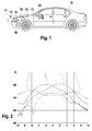
- Figur 1
- eine schematische Darstellung der wesentlichen Komponenten eines ACC- Systems bzw. einer adaptiven Geschwindigkeitsregelvorrichtung als Fahreras- sistenzsystem auf dessen Steuereinrichtung ein erfindungsgemäßes Auswerte- verfahren bzw. ein Verfahren zur Kollisionsvermeidung ablaufen kann;
Figur 2- ein schematisches Antennendiagramm eines Radarsensors;
- Figur 3
- ein schematisches Antennendiagramm eines Radarsensors mit einer syntheti- schen Radarstrahlkeule; und
Figur 4- ein schematisches Antennendiagramm eines Radarsensors mit einer weiteren synthetischen Radarstrahlkeule.
- FIG. 1
- a schematic representation of the essential components of an ACC system or an adaptive cruise control device as a driver assistance system on whose control device an inventive evaluation process or a method for collision avoidance can run;
- FIG. 2
- a schematic antenna diagram of a radar sensor;
- FIG. 3
- a schematic antenna diagram of a radar sensor with a synthetic radar beam lobe; and
- FIG. 4
- a schematic antenna diagram of a radar sensor with another synthetic radar beam lobe.
Ein in
Die während des Einsatzes in regelmäßigen Zeitabständen, z. B. alle 10 ms empfangenen Radarrohdaten werden in der ACC-Steuereinheit 14 ausgewertet, um einzelne Zielobjekte zu identifizieren und zu verfolgen und um insbesondere ein unmittelbar auf der eigenen Fahrspur vorausfahrendes Fahrzeug zu erkennen und als Zielobjekt auszuwählen. Durch Befehle an die Antriebs-Steuereinheit 18 und die Bremssystem-Steuereinheit 20 regelt die ACC-Steuereinheit 14 als Einrichtung zur Bestimmung des Beschleunigungs- und Verzögerungsbedarfs die Geschwindigkeit des Fahrzeugs 10. Wenn kein vorausfahrendes Fahrzeug geortet wird, regelt die ACC-Steuereinheit 14 die Geschwindigkeit des Kraftfahrzeugs 10 auf eine vom Fahrer gewählte Wunschgeschwindigkeit. Ist dagegen ein vorausfahrendes Fahrzeug, dessen Geschwindigkeit kleiner ist als die des eigenen Fahrzeugs, als Zielobjekt erfasst worden, so wird die Geschwindigkeit des Kraftfahrzeugs 10 derart geregelt, dass ein angemessener Abstand zu dem vorausfahrenden Fahrzeug eingehalten wird. Des weiteren kann im Rahmen des Fahrerassistenzsystems ein Verfahren zur Kollisionsvermeidung für das Kraftfahrzeug 10, bei welchem bei wenigstens einem sich während der Fahrt nähernden Hindernis ein Fahrmanöver des Kraftfahrzeugs 10 autonom oder semiautonom durchgeführt oder vorgeschlagen wird, eingesetzt werden.During use at regular intervals, for. B. every 10 ms received radar raw data are evaluated in the
Das Fahrerassistenzsystem bzw. die adaptive Geschwindigkeitsregelvorrichtung 11 bedient sich dabei eines erfindungsgemäßen Auswerteverfahrens zur Objektdetektion mittels des Radarsensors 12, welcher die separaten Radarstrahlkeulen Beam1 bis Beam4, welche einen abzutastenden Winkelbereich abdecken (in den
Das erfindungsgemäße Auswerteverfahren bzw. das Verfahren zur Kollisionsvermeidung für das Kraftfahrzeug 10 ist vorzugsweise als Computerprogramm auf der Steuereinrichtung 14 des Fahrerassistenzsystems 11 des Kraftfahrzeugs 10 bzw. des Radarsensors 12 realisiert, wobei auch andere Lösungen selbstverständlich in Frage kommen. Dazu ist das Computerprogramm in einem Speicherelement der Steuereinrichtung 14 gespeichert. Durch Abarbeitung auf einem Mikroprozessor der Steuereinrichtung 14 wird das Verfahren ausgeführt. Das Computerprogramm kann auf einen computerlesbaren Datenträger (Diskette, CD, DVD, Festplatte, USB-Memory-Stick, Speicherkarte oder dergleichen) oder einem Internetserver als Computerprogrammprodukt gespeichert sein und von dort aus in das Speicherelement der Steuereinrichtung 14 übertragen werden.The evaluation method according to the invention or the method for collision avoidance for the
Claims (9)
Applications Claiming Priority (1)
| Application Number | Priority Date | Filing Date | Title |
|---|---|---|---|
| DE102007058241.4A DE102007058241B4 (en) | 2007-12-04 | 2007-12-04 | Evaluation method, in particular for a driver assistance system of a motor vehicle, for object detection using a radar sensor |
Publications (2)
| Publication Number | Publication Date |
|---|---|
| EP2068172A2 true EP2068172A2 (en) | 2009-06-10 |
| EP2068172A3 EP2068172A3 (en) | 2010-03-24 |
Family
ID=40361654
Family Applications (1)
| Application Number | Title | Priority Date | Filing Date |
|---|---|---|---|
| EP08105549A Ceased EP2068172A3 (en) | 2007-12-04 | 2008-10-10 | Adaptive nulling in monopulse difference antenna diagram to improve the angular resolution at object locations |
Country Status (3)
| Country | Link |
|---|---|
| US (1) | US8035548B2 (en) |
| EP (1) | EP2068172A3 (en) |
| DE (1) | DE102007058241B4 (en) |
Families Citing this family (4)
| Publication number | Priority date | Publication date | Assignee | Title |
|---|---|---|---|---|
| DE102007058241B4 (en) * | 2007-12-04 | 2022-07-07 | Robert Bosch Gmbh | Evaluation method, in particular for a driver assistance system of a motor vehicle, for object detection using a radar sensor |
| US8035545B2 (en) * | 2009-03-13 | 2011-10-11 | Raytheon Company | Vehicular surveillance system using a synthetic aperture radar |
| DE102016202112A1 (en) * | 2016-02-12 | 2017-08-17 | Robert Bosch Gmbh | Radar sensor for driver assistance systems in motor vehicles |
| KR102628655B1 (en) | 2018-06-29 | 2024-01-24 | 삼성전자주식회사 | Method and device to operate radar |
Citations (10)
| Publication number | Priority date | Publication date | Assignee | Title |
|---|---|---|---|---|
| US5926128A (en) | 1972-11-01 | 1999-07-20 | The Marconi Company Limited | Radar systems |
| US6005511A (en) | 1995-03-01 | 1999-12-21 | The Ohio State University | Highway vehicle guidance system |
| DE19934670A1 (en) | 1999-05-26 | 2000-12-21 | Bosch Gmbh Robert | Object detection system |
| DE10027345A1 (en) * | 1999-06-03 | 2001-02-08 | Denso Corp | Monopulse radar device determines change in angle direction data occurring in each monopulse area in succession and derives target object angular directions from changes in data |
| GB2367438A (en) | 2000-09-29 | 2002-04-03 | Jaguar Cars | Monopulse radar for automotive cruise control |
| US6549158B1 (en) | 1977-07-28 | 2003-04-15 | Raytheon Company | Shipboard point defense system and elements therefor |
| EP1391748A1 (en) | 2001-05-30 | 2004-02-25 | Hitachi, Ltd. | Radar device |
| EP1420265A1 (en) | 2002-11-15 | 2004-05-19 | M/A-Com, Inc. | Vehicle front-end sensor for range and bearing measurement of an object |
| EP1548458A2 (en) | 2003-11-26 | 2005-06-29 | Hitachi, Ltd. | Vehicle-mounted radar |
| DE102005060875A1 (en) | 2005-12-20 | 2007-06-21 | Robert Bosch Gmbh | Method and device for signal processing at an angle determination by means of microwave motion sensors |
Family Cites Families (13)
| Publication number | Priority date | Publication date | Assignee | Title |
|---|---|---|---|---|
| US5173702A (en) * | 1980-12-29 | 1992-12-22 | Raytheon Company | All weather tactical strike system (AWTSS) and method of operation |
| JP2567332B2 (en) * | 1993-02-17 | 1996-12-25 | 本田技研工業株式会社 | Time division radar system |
| JP2989428B2 (en) | 1993-06-17 | 1999-12-13 | 本田技研工業株式会社 | Time-sharing FM radar system |
| US5402129A (en) * | 1993-08-04 | 1995-03-28 | Vorad Safety Systems, Inc. | Monopulse azimuth radar system for automotive vehicle tracking |
| DE19530065A1 (en) | 1995-07-01 | 1997-01-09 | Bosch Gmbh Robert | Monostatic FMCW radar sensor |
| JP3622565B2 (en) * | 1999-03-31 | 2005-02-23 | 株式会社デンソー | Radar equipment |
| US7068211B2 (en) * | 2000-02-08 | 2006-06-27 | Cambridge Consultants Limited | Methods and apparatus for obtaining positional information |
| EP1873551B1 (en) * | 2000-08-16 | 2019-03-06 | Valeo Radar Systems, Inc. | Automotive radar systems and techniques |
| DE10256524A1 (en) * | 2002-12-04 | 2004-07-01 | Robert Bosch Gmbh | Device for measuring angular positions |
| DE10303587A1 (en) | 2003-01-30 | 2004-08-12 | Robert Bosch Gmbh | Angle-resolving location device for motor vehicles has multi-beam radar sensor, evaluation device has device that filters amplitudes with at least one amplitude received in preceding measurement cycle |
| US6844849B1 (en) | 2003-07-10 | 2005-01-18 | Codar Ocean Sensors, Ltd. | Circular superdirective receive antenna arrays |
| WO2005026769A1 (en) * | 2003-09-11 | 2005-03-24 | Mitsubishi Denki Kabushiki Kaisha | Radar device |
| DE102007058241B4 (en) * | 2007-12-04 | 2022-07-07 | Robert Bosch Gmbh | Evaluation method, in particular for a driver assistance system of a motor vehicle, for object detection using a radar sensor |
-
2007
- 2007-12-04 DE DE102007058241.4A patent/DE102007058241B4/en active Active
-
2008
- 2008-10-10 EP EP08105549A patent/EP2068172A3/en not_active Ceased
- 2008-11-14 US US12/291,952 patent/US8035548B2/en active Active
Patent Citations (10)
| Publication number | Priority date | Publication date | Assignee | Title |
|---|---|---|---|---|
| US5926128A (en) | 1972-11-01 | 1999-07-20 | The Marconi Company Limited | Radar systems |
| US6549158B1 (en) | 1977-07-28 | 2003-04-15 | Raytheon Company | Shipboard point defense system and elements therefor |
| US6005511A (en) | 1995-03-01 | 1999-12-21 | The Ohio State University | Highway vehicle guidance system |
| DE19934670A1 (en) | 1999-05-26 | 2000-12-21 | Bosch Gmbh Robert | Object detection system |
| DE10027345A1 (en) * | 1999-06-03 | 2001-02-08 | Denso Corp | Monopulse radar device determines change in angle direction data occurring in each monopulse area in succession and derives target object angular directions from changes in data |
| GB2367438A (en) | 2000-09-29 | 2002-04-03 | Jaguar Cars | Monopulse radar for automotive cruise control |
| EP1391748A1 (en) | 2001-05-30 | 2004-02-25 | Hitachi, Ltd. | Radar device |
| EP1420265A1 (en) | 2002-11-15 | 2004-05-19 | M/A-Com, Inc. | Vehicle front-end sensor for range and bearing measurement of an object |
| EP1548458A2 (en) | 2003-11-26 | 2005-06-29 | Hitachi, Ltd. | Vehicle-mounted radar |
| DE102005060875A1 (en) | 2005-12-20 | 2007-06-21 | Robert Bosch Gmbh | Method and device for signal processing at an angle determination by means of microwave motion sensors |
Also Published As
| Publication number | Publication date |
|---|---|
| EP2068172A3 (en) | 2010-03-24 |
| DE102007058241B4 (en) | 2022-07-07 |
| US20090140913A1 (en) | 2009-06-04 |
| DE102007058241A1 (en) | 2009-06-10 |
| US8035548B2 (en) | 2011-10-11 |
Similar Documents
| Publication | Publication Date | Title |
|---|---|---|
| EP2068173B1 (en) | Method for measuring cross movements in a driver assist system | |
| EP1276626B1 (en) | Distance-related method for controlling the speed of a vehicle | |
| EP1277064B1 (en) | Method for adjusting the speed of a motor vehicle | |
| EP1797450B1 (en) | Radar sensor and method for regulating the distance and speed | |
| EP1577682B1 (en) | Object locating system for vehicles to recognize lane change | |
| EP1671196B1 (en) | Method and device for lane recognition for a vehicle | |
| EP3495840A1 (en) | Method and device for locating a vehicle | |
| DE112010005193T5 (en) | Obstacle detection device | |
| EP1912844B1 (en) | Method for the creation of environmental hypotheses for driver assistance functions | |
| DE102007024391A1 (en) | Collision warning device with guardrail detection | |
| DE102014116014A1 (en) | Method for operating a driver assistance system of a motor vehicle, driver assistance system and motor vehicle | |
| EP2908153A2 (en) | Detection of dynamic objects by means of ultrasound | |
| EP3151035A1 (en) | Method for operating radar sensors in a motor vehicle and motor vehicle | |
| DE102010003375B4 (en) | Environment evaluation system in a vehicle with sensor means for detecting objects in the vicinity of the vehicle | |
| DE102015009382A1 (en) | Method for radar-based determination of a height of an object | |
| DE102007058241B4 (en) | Evaluation method, in particular for a driver assistance system of a motor vehicle, for object detection using a radar sensor | |
| DE19754220B4 (en) | Method and device for detecting an impending or potential collision | |
| EP3374791A1 (en) | Lateral crash barrier recognition by means of a distance sensor in a motor vehicle | |
| DE102010029637B4 (en) | Method for object tracking in a positioning system and positioning system | |
| DE19828160B4 (en) | Method for automatic recognition of the main roadway in a multi-lane route | |
| EP1185883A1 (en) | Model-supported allocation of vehicles to traffic lanes | |
| DE102014218351A1 (en) | Method and system for position determination | |
| EP1433002B1 (en) | Method for determining the position of a target object and radar system operating with said method | |
| DE10335898A1 (en) | Driver assistance system with means for detecting moving and stationary objects in front of the driver's vehicle, whereby evaluation of stationary objects is improved by accessing the behavior of moving objects | |
| DE102019201088A1 (en) | Method for recognizing road markings |
Legal Events
| Date | Code | Title | Description |
|---|---|---|---|
| PUAI | Public reference made under article 153(3) epc to a published international application that has entered the european phase |
Free format text: ORIGINAL CODE: 0009012 |
|
| AK | Designated contracting states |
Kind code of ref document: A2 Designated state(s): AT BE BG CH CY CZ DE DK EE ES FI FR GB GR HR HU IE IS IT LI LT LU LV MC MT NL NO PL PT RO SE SI SK TR |
|
| AX | Request for extension of the european patent |
Extension state: AL BA MK RS |
|
| PUAL | Search report despatched |
Free format text: ORIGINAL CODE: 0009013 |
|
| AK | Designated contracting states |
Kind code of ref document: A3 Designated state(s): AT BE BG CH CY CZ DE DK EE ES FI FR GB GR HR HU IE IS IT LI LT LU LV MC MT NL NO PL PT RO SE SI SK TR |
|
| AX | Request for extension of the european patent |
Extension state: AL BA MK RS |
|
| 17P | Request for examination filed |
Effective date: 20100924 |
|
| 17Q | First examination report despatched |
Effective date: 20101015 |
|
| AKX | Designation fees paid |
Designated state(s): DE FR GB IT |
|
| STAA | Information on the status of an ep patent application or granted ep patent |
Free format text: STATUS: THE APPLICATION HAS BEEN REFUSED |
|
| 18R | Application refused |
Effective date: 20160423 |