EP1391587A1 - Abgasturbolader - Google Patents
Abgasturbolader Download PDFInfo
- Publication number
- EP1391587A1 EP1391587A1 EP02018633A EP02018633A EP1391587A1 EP 1391587 A1 EP1391587 A1 EP 1391587A1 EP 02018633 A EP02018633 A EP 02018633A EP 02018633 A EP02018633 A EP 02018633A EP 1391587 A1 EP1391587 A1 EP 1391587A1
- Authority
- EP
- European Patent Office
- Prior art keywords
- exhaust gas
- housing
- shaft
- gas turbocharger
- radial
- Prior art date
- Legal status (The legal status is an assumption and is not a legal conclusion. Google has not performed a legal analysis and makes no representation as to the accuracy of the status listed.)
- Granted
Links
- 238000013016 damping Methods 0.000 claims abstract description 12
- 230000033001 locomotion Effects 0.000 claims description 10
- 230000003534 oscillatory effect Effects 0.000 claims 1
- 238000002485 combustion reaction Methods 0.000 description 4
- 230000004907 flux Effects 0.000 description 3
- 239000000463 material Substances 0.000 description 3
- XEEYBQQBJWHFJM-UHFFFAOYSA-N Iron Chemical compound [Fe] XEEYBQQBJWHFJM-UHFFFAOYSA-N 0.000 description 2
- 230000000694 effects Effects 0.000 description 2
- 230000001419 dependent effect Effects 0.000 description 1
- 238000011161 development Methods 0.000 description 1
- 230000018109 developmental process Effects 0.000 description 1
- 238000005516 engineering process Methods 0.000 description 1
- 230000005484 gravity Effects 0.000 description 1
- 229910052742 iron Inorganic materials 0.000 description 1
- 239000000314 lubricant Substances 0.000 description 1
- 238000005461 lubrication Methods 0.000 description 1
- 230000010355 oscillation Effects 0.000 description 1
- 230000002093 peripheral effect Effects 0.000 description 1
- 238000007789 sealing Methods 0.000 description 1
- 230000006641 stabilisation Effects 0.000 description 1
- 238000011105 stabilization Methods 0.000 description 1
Images

Classifications
-
- F—MECHANICAL ENGINEERING; LIGHTING; HEATING; WEAPONS; BLASTING
- F01—MACHINES OR ENGINES IN GENERAL; ENGINE PLANTS IN GENERAL; STEAM ENGINES
- F01D—NON-POSITIVE DISPLACEMENT MACHINES OR ENGINES, e.g. STEAM TURBINES
- F01D25/00—Component parts, details, or accessories, not provided for in, or of interest apart from, other groups
- F01D25/16—Arrangement of bearings; Supporting or mounting bearings in casings
- F01D25/162—Bearing supports
- F01D25/164—Flexible supports; Vibration damping means associated with the bearing
-
- F—MECHANICAL ENGINEERING; LIGHTING; HEATING; WEAPONS; BLASTING
- F16—ENGINEERING ELEMENTS AND UNITS; GENERAL MEASURES FOR PRODUCING AND MAINTAINING EFFECTIVE FUNCTIONING OF MACHINES OR INSTALLATIONS; THERMAL INSULATION IN GENERAL
- F16C—SHAFTS; FLEXIBLE SHAFTS; ELEMENTS OR CRANKSHAFT MECHANISMS; ROTARY BODIES OTHER THAN GEARING ELEMENTS; BEARINGS
- F16C39/00—Relieving load on bearings
- F16C39/06—Relieving load on bearings using magnetic means
- F16C39/063—Permanent magnets
-
- F—MECHANICAL ENGINEERING; LIGHTING; HEATING; WEAPONS; BLASTING
- F05—INDEXING SCHEMES RELATING TO ENGINES OR PUMPS IN VARIOUS SUBCLASSES OF CLASSES F01-F04
- F05D—INDEXING SCHEME FOR ASPECTS RELATING TO NON-POSITIVE-DISPLACEMENT MACHINES OR ENGINES, GAS-TURBINES OR JET-PROPULSION PLANTS
- F05D2220/00—Application
- F05D2220/40—Application in turbochargers
-
- F—MECHANICAL ENGINEERING; LIGHTING; HEATING; WEAPONS; BLASTING
- F05—INDEXING SCHEMES RELATING TO ENGINES OR PUMPS IN VARIOUS SUBCLASSES OF CLASSES F01-F04
- F05D—INDEXING SCHEME FOR ASPECTS RELATING TO NON-POSITIVE-DISPLACEMENT MACHINES OR ENGINES, GAS-TURBINES OR JET-PROPULSION PLANTS
- F05D2240/00—Components
- F05D2240/50—Bearings
- F05D2240/51—Magnetic
- F05D2240/511—Magnetic with permanent magnets
-
- F—MECHANICAL ENGINEERING; LIGHTING; HEATING; WEAPONS; BLASTING
- F16—ENGINEERING ELEMENTS AND UNITS; GENERAL MEASURES FOR PRODUCING AND MAINTAINING EFFECTIVE FUNCTIONING OF MACHINES OR INSTALLATIONS; THERMAL INSULATION IN GENERAL
- F16C—SHAFTS; FLEXIBLE SHAFTS; ELEMENTS OR CRANKSHAFT MECHANISMS; ROTARY BODIES OTHER THAN GEARING ELEMENTS; BEARINGS
- F16C2360/00—Engines or pumps
- F16C2360/23—Gas turbine engines
- F16C2360/24—Turbochargers
Definitions
- the invention relates to an exhaust gas turbocharger with a housing and in the housing rotatable about its longitudinal axis shaft on which a Turbine wheel and a compressor wheel sit and that in radial bearings and at least an axial bearing is guided, the radial bearing being a passive permanent magnetic Bearings are formed, each one on the shaft seated bearing disc as a rotor and at least one of these at least have one side axially opposite stator.
- Exhaust gas turbochargers serve to improve efficiency and thus the performance increase of internal combustion engines. You point a wave on one end with a turbine wheel and the other end with a compressor wheel is provided.
- the turbine wheel is driven by the exhaust gas flow from the Internal combustion engine applied, wherein essentially part of the thermal Exhaust gas energy by the turbine wheel in a rotary motion is implemented.
- the compressor wheel is driven via the shaft, that draws in fresh air and pressurizes it into the intake ducts of the internal combustion engine can flow in and thus improve the degree of filling.
- a magnetic bearing of the shaft promises the advantage that the use of oil as a lubricant can be dispensed with. Let it through comply with strict emissions standards for vehicles and reliability increase the tubo charger. Magnetic bearings also offer the advantage reducing or even avoiding the balancing of the rotating Components because these bearings keep the rotor in its center of gravity. At one point, magnetic bearings are the traditional oil-lubricated ones However, plain bearings are inferior - they have almost none Damping. This is imperative for external suggestions, for example through the internal combustion engine, dampen and the radial movement of the rotor to that specified by the existing radial gaps Game, limit. The damping must be by additional constructive Measures are provided.
- the invention is therefore based on the object of mounting an exhaust gas turbocharger to be designed so that when using permanent magnetic Radial bearings a sufficient damping of radial movements of the rotor is reached.
- each have a resilient element for radial Damping of vibratory movements of the shaft is arranged.
- the resilient Elements are caused by radial movements of the stators In this way, pressure takes up and hinders the radial movements the wave and have a dampening effect.
- the parts fixed to the housing can be fitted with housing disks with a Stator axially projecting flange extension be formed, the resilient Element preferably with a radially outer surface of the Stator on the one hand and a radially inner surface of the housing-fixed Batch, on the other hand, is connected without gaps.
- the stator is preferably axially and radially enclosing the rotor Cross section U-shaped yoke and there can be two radial bearings be present, between which at least one thrust bearing is arranged.
- the radial bearings within the turbocharger should be one if possible have a large distance around a large lever arm for any occurring To have tilting movements of the shaft.
- a positive system rigidity, i.e. a stable radial bearing system results for bearing distances that are larger are the average diameter of the bearing rings.
- the resilient element is in a preferred embodiment of the invention formed as a cylindrical ring arranged coaxially to the shaft. hereby a uniform damping effect is achieved over the entire circumference.
- the oscillations or vibrations that occur during operation of the turbocharger of the rotating parts depend among other things on their mass and mechanical rigidity. This requires a certain spring stiffness and damping constant of the resilient element by suitable Choice of material composition of the element can be provided can.
- the resilient element preferably has a spring stiffness between 200 kN / m and 600 kN / m and a damping constant between 100 kg / s and 300 kg / s. These values can be easily can be achieved by the resilient element made of a plastic, preferably consists of rubber.
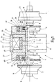
- the exhaust gas turbocharger 1 shown in Fig. 1 has a shaft 2, on its left-hand end of a compressor wheel 3 and at the right-hand end a turbine wheel 4 sit.
- the compressor wheel 3 is in a manner known per se designed as a radial compressor.
- the radial bearings 5, 6 are the compressor wheel 3 and the turbine wheel 4 adjacent. There are grooves 7, 8 between them, which accommodate the Sealing rings are used, being limiting bearings with a typical game of approx. ⁇ 0.15 mm. There is a between the radial bearings 5, 6 Thrust bearing 9.
- the shaft 2 is from surround a total of six rings that are against a collar 10 on shaft 2 are axially clamped.
- a first shaft sleeve 11 with the groove 7 is followed by one Bearing plate 12, a second shaft sleeve 13, a bearing plate 14, one third shaft sleeve 15 and a further bearing disk 16.
- the bearing disks 12, 16 belong to the radial bearings 5, 6. You will each on both sides by a U-shaped cross-section, the shaft 2 coaxial surrounding yoke 17, 18, each yoke 17, 18 a pair of Radial bearing stators 19, 20 and 21, 22 which the legs of the yokes 17, 18, form.
- the radial bearing stators 19, 20, 21, 22 and the bearing washers 12, 16 have permanent magnets 23, 24, 25, 26 and 27, 28, 29, 30, respectively face each other in the axial direction in the two radial bearings 5, 6. They are so polarized that they attract each other, so that in the gaps between the bearing plates 12, 16 and the radial bearing stators 19, 20, 21, 22 results in an axially directed and attractive magnetic field.
- the magnetic fields center the shaft 2, with a radial rigidity of for example 160 kN / m is reached.
- the permanent magnets 23 to 30 each consist of nine coaxially one inside the other set ring magnet 34 as from the enlarged view of the Radial bearing 6 can be seen in Fig. 2.
- the ring magnets 34 of a permanent magnet 23 to 30 lie against one another in the radial direction without a gap.
- Two ring elements 34 adjacent in the radial direction are opposite axially magnetized.
- the ring magnets opposite in the axial direction 34 of two adjacent permanent magnets 23 to 30 are themselves mutually attractively polarized, so that an axial magnetic flux arises.
- the yokes 17, 18 are radially on the outside of spring-elastic elements 60, 61 surround the formed as cylindrical rings made of plastic material are.
- the rings 60, 61 are gap-free with the radially outer surface the yokes 17, 18 on the one hand and the radially inner surface of a Yokes 17, 18 axially overlapping flange of housing washers 37, 38 on the other hand connected.
- the housing washers 37, 38 are in the Drawing not shown connected to the turbocharger housing.
- the rings 60, 61 are caused by radial movements of the yokes 17, 18 In this way, pressure takes up and dampens the radial movement.
- the Spring stiffness of the rings 60, 61 is in the range from 200 kN / m to k600 N / m.
- the damping constant of the rings 60, 61 is approximately 100 kg / s to 300 kg / s.
- the bearing disc 14 belongs to the thrust bearing 9. It is on both sides by one Ring yoke 47 made from laminated SI iron.
- the ring yoke is 47 edged and fixed between the two housing disks 37, 38. It has an outer yoke shell 48, of which two inwardly directed yoke legs 49, 50 go out, have the L-shaped cross section and with each other facing the leg sections, the bearing disc 14, whereby two magnetic gaps 51, 52 arise.
- the peripheral side of the bearing washer 14 adjacent are two within the ring yoke 47 axially adjacent permanent magnets 53, 54, which - symbolizes through the triangles - are oppositely axially polarized. they lay to each other and to the yoke legs 49, 50. They are from an electromagnetic Ring coil 55 surround the space between the Permanent magnets 53, 54 and the yoke shell 48 and the yoke legs 49, 50 fills out.
- Axial stabilization can be effected via the axial bearing 9. This happens with an axial deflection of the bearing plate 14 in that this deflection from a not shown here, in the state of the Technology known sensor is detected and thus also not shown controller controls the current flow to the ring coil 55 so that an additional magnetic flux is generated which results in an asymmetrical overall Magnetic flux distribution within the axial bearing 9 leads to the deflection counteracts the bearing disc.
Landscapes
- Engineering & Computer Science (AREA)
- General Engineering & Computer Science (AREA)
- Mechanical Engineering (AREA)
- Support Of The Bearing (AREA)
- Supercharger (AREA)
- Vibration Prevention Devices (AREA)
- Magnetic Bearings And Hydrostatic Bearings (AREA)
Abstract
Description
- Fig. 1
- die Seitenansicht eines Abgasturboladers ohne Gehäuse mit Teilschnittdarstellung des oberen Teils der Lagerung der Welle; und
- Fig. 2
- einen Querschnitt durch ein Radiallager des Abgasturboladers gemäß Fig. 1.
Claims (9)
- Abgasturbolader (1) mit einem Gehäuse und einer im Gehäuse um ihre Längsachse drehbar angeordneten Welle (2), auf der ein Turbinenrad (4) und ein Verdichterrad (3) sitzen und die in Radiallagern (5, 6) und wenigstens einem Axiallager (9) geführt ist, wobei die Radiallager (5, 6) als passive permanentmagnetische Lager ausgebildet sind, die jeweils eine auf der Welle (2) sitzende Lagerscheibe (12, 16) als Rotor und wenigstens einen diesem an zumindest einer Seite axial gegenüberliegenden Stator (19, 20, 21, 22) aufweisen, dadurch gekennzeichnet, dass zwischen dem Stator (19, 20, 21, 22) und einer gehäusefesten Partie (37, 38) jeweils ein federelastisches Element (60, 61) zur radialen Dämpfung von Schwingungsbewegungen der Welle (2) angeordnet ist.
- Abgasturbolader nach Anspruch 1, dadurch gekennzeichnet, dass die gehäusefesten Partien durch Gehäusescheiben (37, 38) mit einem den Stator (19, 20, 21, 22) axial überragenden Flanschfortsatz gebildet sind.
- Abgasturbolader nach Anspruch 1 oder 2, dadurch gekennzeichnet, dass das federelastische Element (60, 61) mit einer radial außen liegenden Fläche des Stators (19, 20, 21, 22) einerseits und einer radial innen liegenden Fläche der gehäusefesten Partie andererseits spaltfrei verbunden ist.
- Abgasturbolader nach einem der Ansprüche 1 bis 3, dadurch gekennzeichnet, dass das federelastische Element (60, 61) als koaxial zur Welle (2) angeordneter, zylindrischer Ring ausgebildet ist.
- Abgasturbolader nach einem der Ansprüche 1 bis 4, dadurch gekennzeichnet, dass das federelastische Element (60, 61) eine Federsteifigkeit zwischen 200 kN/m und 600 kN/m aufweist.
- Abgasturbolader nach einem der Ansprüche 1 bis 5, dadurch gekennzeichnet, dass das federelastische Element (60, 61) eine Dämpfungskonstante zwischen 100 kg/s und 300 kg/s aufweist.
- Abgasturbolader nach einem der Ansprüche 1 bis 6, dadurch gekennzeichnet, dass das federelastische Element (60, 61) aus einem Kunststoff, vorzugsweise aus Kautschuk besteht.
- Abgasturbolader nach einem der Ansprüche 1 bis 7, dadurch gekennzeichnet, dass der Stator (19, 20, 21, 22) als den Rotor axial und radial einfassendes, im Querschnitt U-förmiges Joch (17, 18) ausgebildet ist.
- Abgasturbolader nach einem der Ansprüche 1 bis 8, dadurch gekennzeichnet, dass zwei Radiallager (5, 6) vorhanden sind, zwischen denen wenigstens ein Axiallager (9) angeordnet ist.
Priority Applications (4)
| Application Number | Priority Date | Filing Date | Title |
|---|---|---|---|
| EP02018633A EP1391587B1 (de) | 2002-08-20 | 2002-08-20 | Abgasturbolader |
| DE50214471T DE50214471D1 (de) | 2002-08-20 | 2002-08-20 | Abgasturbolader |
| JP2003286628A JP4413553B2 (ja) | 2002-08-20 | 2003-08-05 | 排気タービン過給機 |
| US10/643,195 US6846167B2 (en) | 2002-08-20 | 2003-08-18 | Turbocharger with magnetic bearing system that includes dampers |
Applications Claiming Priority (1)
| Application Number | Priority Date | Filing Date | Title |
|---|---|---|---|
| EP02018633A EP1391587B1 (de) | 2002-08-20 | 2002-08-20 | Abgasturbolader |
Publications (2)
| Publication Number | Publication Date |
|---|---|
| EP1391587A1 true EP1391587A1 (de) | 2004-02-25 |
| EP1391587B1 EP1391587B1 (de) | 2010-06-02 |
Family
ID=30775817
Family Applications (1)
| Application Number | Title | Priority Date | Filing Date |
|---|---|---|---|
| EP02018633A Expired - Lifetime EP1391587B1 (de) | 2002-08-20 | 2002-08-20 | Abgasturbolader |
Country Status (4)
| Country | Link |
|---|---|
| US (1) | US6846167B2 (de) |
| EP (1) | EP1391587B1 (de) |
| JP (1) | JP4413553B2 (de) |
| DE (1) | DE50214471D1 (de) |
Cited By (3)
| Publication number | Priority date | Publication date | Assignee | Title |
|---|---|---|---|---|
| CN112503099A (zh) * | 2020-11-23 | 2021-03-16 | 人本股份有限公司 | 轴承轴向安装缓震轴承座 |
| CN113931929A (zh) * | 2021-09-16 | 2022-01-14 | 上海工程技术大学 | 一种可自主减振降噪的滚动轴承装置 |
| CN114382550A (zh) * | 2020-10-19 | 2022-04-22 | 通用电气公司 | 用于阻尼轴振动的阻尼装置 |
Families Citing this family (16)
| Publication number | Priority date | Publication date | Assignee | Title |
|---|---|---|---|---|
| DE10216421A1 (de) * | 2002-04-12 | 2003-10-30 | Forschungszentrum Juelich Gmbh | Magnetführungseinrichtung |
| DE10216447C1 (de) * | 2002-04-12 | 2003-09-18 | Forschungszentrum Juelich Gmbh | Abgasturbolader |
| DE50213007D1 (de) * | 2002-08-20 | 2008-12-24 | Borgwarner Inc | Abgasturbolader |
| US20060137342A1 (en) * | 2004-12-14 | 2006-06-29 | Borgwarner Inc. | Turbine flow regulating valve system |
| US20060137343A1 (en) * | 2004-12-14 | 2006-06-29 | Borgwarner Inc. | Turbine flow regulating valve system |
| WO2007066474A1 (ja) * | 2005-12-09 | 2007-06-14 | Ntn Corporation | モータ一体型の磁気軸受装置 |
| DE112006003310T5 (de) * | 2005-12-09 | 2008-11-06 | Ntn Corporation | Magnetlagervorrichtung |
| KR100853658B1 (ko) * | 2007-05-25 | 2008-08-25 | 한국과학기술연구원 | 압축기 |
| DE102008050314A1 (de) | 2008-08-18 | 2010-02-25 | Daimler Ag | Verdichter und Verfahren zum Betreiben eines Verdichters sowie Brennstoffzelleneinrichtung mit einem Verdichter |
| IT1393321B1 (it) * | 2009-03-16 | 2012-04-20 | Electron S R L D | Cuscinetti magnetici radiale e assiale smorzatori di vibrazioni, sistema di supporto a levitazione magnetica per rotore, con smorzamento di vibrazioni, misura statica e dinamica di sforzo, compensazione di allungamento termico. |
| CN102597498A (zh) | 2009-10-29 | 2012-07-18 | 海洋能源公司 | 能量转换系统和方法 |
| DE102012012540A1 (de) * | 2012-06-26 | 2014-01-02 | Robert Bosch Gmbh | Turboverdichter |
| US10539160B2 (en) | 2017-04-19 | 2020-01-21 | Garrett Transportation I Inc | Damping system for an e-charger |
| US11451108B2 (en) * | 2017-08-16 | 2022-09-20 | Ifit Inc. | Systems and methods for axial impact resistance in electric motors |
| CN110566590B (zh) * | 2019-09-12 | 2021-02-12 | 中国科学院理化技术研究所 | 一种对中结构、对中装置和旋转设备 |
| US11221054B2 (en) | 2019-11-26 | 2022-01-11 | Garrett Transportation I Inc | E-charger with hybrid dampening system |
Citations (4)
| Publication number | Priority date | Publication date | Assignee | Title |
|---|---|---|---|---|
| DE1526439A1 (de) * | 1966-03-03 | 1970-02-12 | Kuehnle Kopp Kausch Ag | Abgasturbolader mit beidseitig an der Welle fliegend angeordnetem Turbinen- und Geblaeselaufrad |
| DE2314436A1 (de) * | 1973-03-23 | 1977-12-29 | Boehringer Andreas | Lagerungs- und daempfungseinrichtung zur stabilisierung der rotorbewegung schnell umlaufender zentrifugen |
| EP0087197A1 (de) * | 1982-02-22 | 1983-08-31 | BBC Aktiengesellschaft Brown, Boveri & Cie. | Antrieb und Lagerung eines Turboverdichters |
| US5521448A (en) | 1994-08-01 | 1996-05-28 | Mechanical Technology Incorporated | Damping for passive magnetic bearings |
Family Cites Families (3)
| Publication number | Priority date | Publication date | Assignee | Title |
|---|---|---|---|---|
| JPS5973624A (ja) * | 1982-10-18 | 1984-04-25 | Aisin Seiki Co Ltd | タ−ボチヤ−ジヤ用軸受装置 |
| US5752774A (en) * | 1996-10-22 | 1998-05-19 | Mohawk Innovative Technology, Inc. | Zero clearance auxiliary bearing for providing rotor shock tolerance |
| DE19712711A1 (de) * | 1997-03-26 | 1998-10-01 | Pfeiffer Vacuum Gmbh | Dämpfungssystem für magnetisch gelagerte Rotoren |
-
2002
- 2002-08-20 DE DE50214471T patent/DE50214471D1/de not_active Expired - Lifetime
- 2002-08-20 EP EP02018633A patent/EP1391587B1/de not_active Expired - Lifetime
-
2003
- 2003-08-05 JP JP2003286628A patent/JP4413553B2/ja not_active Expired - Fee Related
- 2003-08-18 US US10/643,195 patent/US6846167B2/en not_active Expired - Fee Related
Patent Citations (4)
| Publication number | Priority date | Publication date | Assignee | Title |
|---|---|---|---|---|
| DE1526439A1 (de) * | 1966-03-03 | 1970-02-12 | Kuehnle Kopp Kausch Ag | Abgasturbolader mit beidseitig an der Welle fliegend angeordnetem Turbinen- und Geblaeselaufrad |
| DE2314436A1 (de) * | 1973-03-23 | 1977-12-29 | Boehringer Andreas | Lagerungs- und daempfungseinrichtung zur stabilisierung der rotorbewegung schnell umlaufender zentrifugen |
| EP0087197A1 (de) * | 1982-02-22 | 1983-08-31 | BBC Aktiengesellschaft Brown, Boveri & Cie. | Antrieb und Lagerung eines Turboverdichters |
| US5521448A (en) | 1994-08-01 | 1996-05-28 | Mechanical Technology Incorporated | Damping for passive magnetic bearings |
Cited By (4)
| Publication number | Priority date | Publication date | Assignee | Title |
|---|---|---|---|---|
| CN114382550A (zh) * | 2020-10-19 | 2022-04-22 | 通用电气公司 | 用于阻尼轴振动的阻尼装置 |
| CN112503099A (zh) * | 2020-11-23 | 2021-03-16 | 人本股份有限公司 | 轴承轴向安装缓震轴承座 |
| CN113931929A (zh) * | 2021-09-16 | 2022-01-14 | 上海工程技术大学 | 一种可自主减振降噪的滚动轴承装置 |
| CN113931929B (zh) * | 2021-09-16 | 2024-01-23 | 上海工程技术大学 | 一种可自主减振降噪的滚动轴承装置 |
Also Published As
| Publication number | Publication date |
|---|---|
| US20040037716A1 (en) | 2004-02-26 |
| JP2004092641A (ja) | 2004-03-25 |
| JP4413553B2 (ja) | 2010-02-10 |
| DE50214471D1 (de) | 2010-07-15 |
| EP1391587B1 (de) | 2010-06-02 |
| US6846167B2 (en) | 2005-01-25 |
Similar Documents
| Publication | Publication Date | Title |
|---|---|---|
| EP1391587B1 (de) | Abgasturbolader | |
| EP1391586B1 (de) | Abgasturbolader | |
| EP0332979B1 (de) | Magnetische Lagerung mit Permanentmagneten zur Aufnahme der radialen Lagerkräfte | |
| EP2503104B1 (de) | Turbomaschine | |
| EP1402186B1 (de) | Abgasturbolader | |
| DE10043235A1 (de) | Vakuumpumpe | |
| EP3775566A1 (de) | Seitenkanalverdichter für ein brennstoffzellensystem zur förderung und/oder verdichtung von einem gasförmigen medium | |
| DE112010001692T5 (de) | Isolier- und dämpfbuchse für eine wälzelementlagerpatrone | |
| DE3931661A1 (de) | Magnetgelagerte vakuumpumpe | |
| DE112013004747T5 (de) | Als halbschwimmender Ring ausgebildetes Zapfenlager mit hydrodynamischen Fluidfilmfestkörpergelenkkippsegmenten und nachgiebigen Dämpfern | |
| DE19543764A1 (de) | Berührungsdichtung für Strömungsmaschinen | |
| WO2013107804A2 (de) | Nassläuferpumpe mit permanentmagnet | |
| DE112013001938T5 (de) | Axiallageranordnung | |
| DE102017009842A1 (de) | Verdichteranordnung zum Betreiben einer Druckluftversorgungsanlage, Druckluftversorgungsanlage, Fahrzeug | |
| DE102013200655B4 (de) | Kombiniertes Radial-Axiallager und Nassläuferpumpe | |
| DE112006000639B4 (de) | Turbolader mit elektrischer Rotationsmaschine einer Brennkraftmaschine | |
| EP2009286B1 (de) | Wellendichtung für eine Turbomaschine | |
| WO2018078150A1 (de) | Rotationssystem mit axialer gaslagerung | |
| WO2004099622A1 (de) | Turbopumpe | |
| EP0893576B1 (de) | Verbindung von rotierenden Bauteilen | |
| EP2284426B1 (de) | Strömungsmaschine | |
| DE102016211308A1 (de) | Rotor für eine elektrische Maschine, elektrische Maschine mit dem Rotor und Herstellungsverfahren für den Rotor | |
| EP1646795A1 (de) | Magnetisches lagerelement | |
| DE19823630C2 (de) | Motorlager für schnelldrehende Kleinmotoren | |
| WO2018158079A1 (de) | Radiallager für strömungsmaschinen |
Legal Events
| Date | Code | Title | Description |
|---|---|---|---|
| PUAI | Public reference made under article 153(3) epc to a published international application that has entered the european phase |
Free format text: ORIGINAL CODE: 0009012 |
|
| AK | Designated contracting states |
Kind code of ref document: A1 Designated state(s): AT BE BG CH CY CZ DE DK EE ES FI FR GB GR IE IT LI LU MC NL PT SE SK TR |
|
| AX | Request for extension of the european patent |
Extension state: AL LT LV MK RO SI |
|
| 17P | Request for examination filed |
Effective date: 20040326 |
|
| AKX | Designation fees paid |
Designated state(s): DE FR GB IT NL |
|
| RAP1 | Party data changed (applicant data changed or rights of an application transferred) |
Owner name: BORGWARNER INC. |
|
| 17Q | First examination report despatched |
Effective date: 20080515 |
|
| GRAP | Despatch of communication of intention to grant a patent |
Free format text: ORIGINAL CODE: EPIDOSNIGR1 |
|
| GRAS | Grant fee paid |
Free format text: ORIGINAL CODE: EPIDOSNIGR3 |
|
| GRAA | (expected) grant |
Free format text: ORIGINAL CODE: 0009210 |
|
| AK | Designated contracting states |
Kind code of ref document: B1 Designated state(s): DE FR GB IT NL |
|
| REG | Reference to a national code |
Ref country code: GB Ref legal event code: FG4D Free format text: NOT ENGLISH |
|
| REF | Corresponds to: |
Ref document number: 50214471 Country of ref document: DE Date of ref document: 20100715 Kind code of ref document: P |
|
| REG | Reference to a national code |
Ref country code: NL Ref legal event code: T3 |
|
| PLBE | No opposition filed within time limit |
Free format text: ORIGINAL CODE: 0009261 |
|
| STAA | Information on the status of an ep patent application or granted ep patent |
Free format text: STATUS: NO OPPOSITION FILED WITHIN TIME LIMIT |
|
| 26N | No opposition filed |
Effective date: 20110303 |
|
| REG | Reference to a national code |
Ref country code: DE Ref legal event code: R097 Ref document number: 50214471 Country of ref document: DE Effective date: 20110302 |
|
| PGFP | Annual fee paid to national office [announced via postgrant information from national office to epo] |
Ref country code: GB Payment date: 20120726 Year of fee payment: 11 |
|
| PGFP | Annual fee paid to national office [announced via postgrant information from national office to epo] |
Ref country code: IT Payment date: 20120809 Year of fee payment: 11 Ref country code: FR Payment date: 20120809 Year of fee payment: 11 |
|
| PGFP | Annual fee paid to national office [announced via postgrant information from national office to epo] |
Ref country code: NL Payment date: 20120813 Year of fee payment: 11 |
|
| REG | Reference to a national code |
Ref country code: NL Ref legal event code: V1 Effective date: 20140301 |
|
| GBPC | Gb: european patent ceased through non-payment of renewal fee |
Effective date: 20130820 |
|
| PG25 | Lapsed in a contracting state [announced via postgrant information from national office to epo] |
Ref country code: NL Free format text: LAPSE BECAUSE OF NON-PAYMENT OF DUE FEES Effective date: 20140301 |
|
| REG | Reference to a national code |
Ref country code: FR Ref legal event code: ST Effective date: 20140430 |
|
| PG25 | Lapsed in a contracting state [announced via postgrant information from national office to epo] |
Ref country code: IT Free format text: LAPSE BECAUSE OF NON-PAYMENT OF DUE FEES Effective date: 20130820 |
|
| PG25 | Lapsed in a contracting state [announced via postgrant information from national office to epo] |
Ref country code: GB Free format text: LAPSE BECAUSE OF NON-PAYMENT OF DUE FEES Effective date: 20130820 |
|
| PG25 | Lapsed in a contracting state [announced via postgrant information from national office to epo] |
Ref country code: FR Free format text: LAPSE BECAUSE OF NON-PAYMENT OF DUE FEES Effective date: 20130902 |
|
| PGFP | Annual fee paid to national office [announced via postgrant information from national office to epo] |
Ref country code: DE Payment date: 20150831 Year of fee payment: 14 |
|
| REG | Reference to a national code |
Ref country code: DE Ref legal event code: R119 Ref document number: 50214471 Country of ref document: DE |
|
| PG25 | Lapsed in a contracting state [announced via postgrant information from national office to epo] |
Ref country code: DE Free format text: LAPSE BECAUSE OF NON-PAYMENT OF DUE FEES Effective date: 20170301 |