EP1391363A1 - Proportional-Relaisventil - Google Patents
Proportional-Relaisventil Download PDFInfo
- Publication number
- EP1391363A1 EP1391363A1 EP03014346A EP03014346A EP1391363A1 EP 1391363 A1 EP1391363 A1 EP 1391363A1 EP 03014346 A EP03014346 A EP 03014346A EP 03014346 A EP03014346 A EP 03014346A EP 1391363 A1 EP1391363 A1 EP 1391363A1
- Authority
- EP
- European Patent Office
- Prior art keywords
- relay
- pressure
- piston
- chamber
- valve
- Prior art date
- Legal status (The legal status is an assumption and is not a legal conclusion. Google has not performed a legal analysis and makes no representation as to the accuracy of the status listed.)
- Withdrawn
Links
- 238000009423 ventilation Methods 0.000 claims 3
- 238000005192 partition Methods 0.000 description 4
- 230000003111 delayed effect Effects 0.000 description 3
- 238000005303 weighing Methods 0.000 description 3
- 238000011161 development Methods 0.000 description 1
- 230000018109 developmental process Effects 0.000 description 1
- 238000006073 displacement reaction Methods 0.000 description 1
- 230000010363 phase shift Effects 0.000 description 1
- 230000002123 temporal effect Effects 0.000 description 1
Images
Classifications
-
- B—PERFORMING OPERATIONS; TRANSPORTING
- B60—VEHICLES IN GENERAL
- B60T—VEHICLE BRAKE CONTROL SYSTEMS OR PARTS THEREOF; BRAKE CONTROL SYSTEMS OR PARTS THEREOF, IN GENERAL; ARRANGEMENT OF BRAKING ELEMENTS ON VEHICLES IN GENERAL; PORTABLE DEVICES FOR PREVENTING UNWANTED MOVEMENT OF VEHICLES; VEHICLE MODIFICATIONS TO FACILITATE COOLING OF BRAKES
- B60T15/00—Construction arrangement, or operation of valves incorporated in power brake systems and not covered by groups B60T11/00 or B60T13/00
- B60T15/02—Application and release valves
- B60T15/18—Triple or other relay valves which allow step-wise application or release and which are actuated by brake-pipe pressure variation to connect brake cylinders or equivalent to compressed air or vacuum source or atmosphere
Definitions
- the invention relates to a proportional relay valve according to the preamble of claim 1.
- Proportional relay valves of the type mentioned are known. They are used, for example, in EBS wheel and axle modulators used and serve as the main actuator of large pneumatic Nominal size for controlling brake pressure to brake cylinders, where z. B. predetermined by control electronics Control pulses by means of solenoid valves in a control pressure for the relay valve. The outlet pressure of the proportional relay valve is proportional to this Control pressure. Pneumatic control of the relay valve is also done by the pressure of a brake value transmitter. Both Relay valves used up to now incline the relay pistons to vibrations, especially resonance vibrations. root cause this is due to the smooth design of the components for the purpose of low hysteresis of the pressure transfer identifier.
- the object of the present invention is a proportional relay valve of the type mentioned above train that the risk of piston vibrations is avoided is and an improved dynamic control engineering Behavior, especially an improved dynamic pressure build-up is achieved.
- a sealed partition is provided, the the outlet chamber into a relay piston chamber and a relay piston facing away from the relay piston divides and which with a device for pressure equalization, for example Orifice or throttle, provided between these two chambers is.
- the partition wall acts as a baffle and shields the relay piston from the dynamic gas flow forces from.
- the arrangement of the partition wall a phase increase of the internal negative feedback in the relay valve generated.
- the modulated brake pressure acts on the Pressure equalization device delayed, d. H. delayed on the relay piston, causing a phase shift the pressure vibrations between the relay pistons and the relay work space connected to the brake cylinders is effected and thus suppresses natural piston vibrations become.
- the relay piston overrides by the invention Training first, what is in a larger pressure gradients, better timing and expresses faster pressure change in the ABS case.
- the invention Relay valve is therefore excellent for ABS-ASR-FDR pressure control and regular operation can be used in EBS systems.
- the dynamic brake pressure build-up is improved.
- This Behavior especially the rise time, can be determined by the Size of the pressure equalization cross section of the device for Pressure equalization, for example the orifice or throttle, is influenced become.
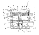
- the drawing shows a proportional relay valve schematically in section 2 with a housing 4 in which a relay piston 6 is arranged to be longitudinally displaceable.
- the proportional relay valve 2 points above the relay piston 6 a control chamber 8 and below the relay piston 6 one Outlet chamber 10 on. Via a control pressure supply line 12 and a control pressure port 14 is control pressure of the control chamber 8 can be supplied or removed from the control chamber 8.
- the outlet chamber 10 is on the one hand via an outlet connection 16 to a leading to a brake cylinder Brake pressure line 18 and on the other hand via a valve device 20 with inlet valve 22 and outlet valve 24 with a supply pressure chamber 26, which with a not shown Pressure source is connected, or with the atmosphere connectable via a vent connection 28.
- the inlet valve 22 is formed by a on the housing 4 arranged outer valve seat 30 and one through a spring 32 biased against the valve seat 30, slidable guided, hollow valve body 34.
- the relay piston 6 has an end piston pin 36, the edge of which as an annular, inner valve seat 38 is formed, which together with the valve body 34 Exhaust valve 24 forms.
- the relay piston 6 delimits with its one surface, which serves as control surface 40, the control chamber 8 and with its other surface, which serves as weighing surface 42, the Outlet chamber 10.
- An intermediate wall 44 is arranged in the outlet chamber 10, which coaxially surrounds the piston pin 36 by means of Seals 52, 54 against the piston pin and the housing is sealed and the outlet chamber 10 in a relay piston side Chamber 46 and a relay piston chamber facing away from the relay piston 48 shares which with the brake pressure line 18 communicates.
- the intermediate wall 44 has at least a device for pressure equalization between the Chamber 46 and the relay working chamber 48, which here as Opening or orifice or throttle 50 is shown over the chamber 46 communicates with relay working chamber 48 stands.
- the device 50 can also be a check valve his.
- the proportional relay valve 2 works as follows:
- Inlet valve 22 becomes the supply pressure chamber 26 with the relay working chamber 48 connected, which in the reservoir pressure chamber 26 pressure medium present via the outlet connection 16 and the brake pressure line 18 in the Consumer circuit, for example a brake cylinder, can flow.
- the aperture or throttle 50 is delayed in time a pressure equalization between the relay working chamber 48 and the relay piston-side chamber 46 to that on the weighing surface 42 of the relay piston 6 acting pressure with the the control surface 40 acting control pressure in equilibrium has been brought.
- the partition 44 with aperture 50 causes thus that the pressure medium flow forces are temporal act on the relay piston 6 with a delay. With this balance the relay piston 6 moves through the valve spring 32 so far back that at the same time the exhaust valve 24 and the inlet valve 22 are closed.
Landscapes
- Engineering & Computer Science (AREA)
- Transportation (AREA)
- Mechanical Engineering (AREA)
- Valves And Accessory Devices For Braking Systems (AREA)
Abstract
Description
Claims (7)
- Proportional-Relaisventil, insbesondere für Rad- und Achsmodulatoren von EBS-Bremssystemen, mitdadurch gekennzeichnet, dass in der Auslasskammer (10) eine Zwischenwand (44) angeordnet ist, die den Relaiskolben (6) gegen ausgesteuerten Druck abschirmt und die Auslasskammer in eine relaiskolbenseitige Kammer (46) und eine relaiskolbenabgewandte Relaisarbeitskammer (48) teilt, welche mit dem Ausgang für den ausgesteuerten Druck in Verbindung steht, undeinem in einem Gehäuse angeordneten, längsbeweglichen Relaiskolben,einer vom Relaiskolben betätigbaren Ventileinrichtung mit Einlass- und Auslassventil,einem Entlüftungskanal, der in der Entlüftungsposition der Ventileinrichtung an einen Entlüftungsanschluss angeschlossen ist,einem Steuerdruckeingang,einer durch eine Steuerfläche des Relaiskolbens und das Gehäuse begrenzten Steuerkammer, die mit dem Steuerdruckeingang verbunden ist,einer Auslasskammer zwischen Relaiskolben und Ventileinrichtung mit einem Ausgang für ausgesteuertes Druckmittel undeiner Vorratsdruckkammer, die mit einem Vorratsdruckeingang in Verbindung steht und die mit dem Ausgang für ausgesteuertes Druckmittel über die Ventileinrichtung verbunden ist,
dass in der Zwischenwand (44) eine Einrichtung (50) zum Druckausgleich zwischen der relaiskolbenseitigen Kammer (46) und der Relaisarbeitskammer (48) angeordnet ist, derart, dass Druckmittelströmungskräfte über die Zwischenwand mit Druckausgleicheinrichtung mit zeitlicher Verzögerung auf den Relaiskolben (6) wirken. - Proportional-Relaisventil nach Anspruch 1, dadurch gekennzeichnet, dass die Zwischenwand (44) einen Relaiskolbenzapfen (36) koaxial umschließt.
- Proportional-Relaisventil nach Anspruch 1 oder 2, dadurch gekennzeichnet, dass die Zwischenwand (44) gegenüber dem Relaiskolben (6) bzw. dem Relaiskolbenzapfen (36), dem Gehäuse und der Zylinderwand (51) abgedichtet ist.
- Proportional-Relaisventil nach einem der Ansprüche 1-3, dadurch gekennzeichnet, dass die Einrichtung (50) zum Druckausgleich durch wenigstens eine die Kammern (46 und 48) verbindende Öffnung, Drossel oder Blende gebildet ist.
- Proportional-Relaisventil nach einem der Ansprüche 1-3, dadurch gekennzeichnet, dass die Einrichtung (50) zum Druckausgleich durch wenigstens ein Rückschlagventil gebildet ist.
- Proportional-Relaisventil nach einem der vorhergehenden Ansprüche, dadurch gekennzeichnet, dass der Druckausgleichsquerschnitt der Einrichtung (50) zum Druckausgleich zwischen den Kammern (46 und 48) einstellbar ist.
- Die Zwischenwand (44) hält die Gasströmungskräfte vom Kolben (6) zeitlich verzögert zurück.
Applications Claiming Priority (2)
| Application Number | Priority Date | Filing Date | Title |
|---|---|---|---|
| DE2002138182 DE10238182A1 (de) | 2002-08-21 | 2002-08-21 | Proportional-Relaisventil |
| DE10238182 | 2002-08-21 |
Publications (1)
| Publication Number | Publication Date |
|---|---|
| EP1391363A1 true EP1391363A1 (de) | 2004-02-25 |
Family
ID=30775471
Family Applications (1)
| Application Number | Title | Priority Date | Filing Date |
|---|---|---|---|
| EP03014346A Withdrawn EP1391363A1 (de) | 2002-08-21 | 2003-06-26 | Proportional-Relaisventil |
Country Status (2)
| Country | Link |
|---|---|
| EP (1) | EP1391363A1 (de) |
| DE (1) | DE10238182A1 (de) |
Cited By (5)
| Publication number | Priority date | Publication date | Assignee | Title |
|---|---|---|---|---|
| DE102009040759A1 (de) | 2009-09-09 | 2011-03-10 | Wabco Gmbh | Relaisventileinrichtung |
| EP3118077A1 (de) | 2015-07-15 | 2017-01-18 | KNORR-BREMSE Systeme für Nutzfahrzeuge GmbH | Relaisventil und verfahren zur steuerung eines relaisventils |
| EP3477168A1 (de) * | 2017-10-28 | 2019-05-01 | WABCO GmbH | Ventil und pneumatische bremsanlage |
| EP3798071A1 (de) * | 2019-09-24 | 2021-03-31 | WABCO Europe BVBA | Pneumatisches ventil für ein bremssystem |
| DE102021103053B3 (de) | 2021-02-10 | 2022-02-03 | Knorr-Bremse Systeme für Nutzfahrzeuge GmbH | Relaisventilvorrichtung und Bremsvorrichtung für ein Fahrzeug mit einer solchen Relaisventilvorrichtung |
Families Citing this family (2)
| Publication number | Priority date | Publication date | Assignee | Title |
|---|---|---|---|---|
| DE102013017875A1 (de) | 2013-10-26 | 2015-05-21 | Wabco Gmbh | Relaisventil, Ventileinrichtung sowie Fahrzeug damit |
| DE102013017876A1 (de) | 2013-10-26 | 2015-04-30 | Wabco Gmbh | Relaisventil, Ventileinrichtung sowie Fahrzeug damit |
Citations (4)
| Publication number | Priority date | Publication date | Assignee | Title |
|---|---|---|---|---|
| DE3515386A1 (de) * | 1985-04-27 | 1986-11-06 | Graubremse Gmbh, 6900 Heidelberg | Insbesondere zweikreisig ansteuerbares anhaengersteuerventil fuer zweileitungs-bremsanlagen |
| DE3612369A1 (de) * | 1986-04-12 | 1987-10-15 | Bosch Gmbh Robert | Anhaengersteuerventil |
| DE3827350A1 (de) * | 1988-08-12 | 1990-02-15 | Bosch Gmbh Robert | Pneumatisches relaisventil |
| EP0582990A1 (de) * | 1992-08-12 | 1994-02-16 | Grau Gmbh | Anhängersteuerventil für Kfz-Bremsanlagen |
Family Cites Families (3)
| Publication number | Priority date | Publication date | Assignee | Title |
|---|---|---|---|---|
| IT1087801B (it) * | 1977-10-28 | 1985-06-04 | Magneti Marelli Spa | Procedimento e relativo dispositivo per la frenatura pneumatica di predominanza di veicoli rimorchiati in genere |
| DE3345332A1 (de) * | 1983-12-15 | 1985-06-27 | Wabco Westinghouse Fahrzeugbremsen GmbH, 3000 Hannover | Relaisventil fuer druckmittel |
| DE3409303A1 (de) * | 1984-03-14 | 1985-09-26 | Graubremse Gmbh, 6900 Heidelberg | Zwischen handbremsventil und federspeicherbremszylinder einsetzbares relaisventil mit druckbegrenzung |
-
2002
- 2002-08-21 DE DE2002138182 patent/DE10238182A1/de not_active Withdrawn
-
2003
- 2003-06-26 EP EP03014346A patent/EP1391363A1/de not_active Withdrawn
Patent Citations (4)
| Publication number | Priority date | Publication date | Assignee | Title |
|---|---|---|---|---|
| DE3515386A1 (de) * | 1985-04-27 | 1986-11-06 | Graubremse Gmbh, 6900 Heidelberg | Insbesondere zweikreisig ansteuerbares anhaengersteuerventil fuer zweileitungs-bremsanlagen |
| DE3612369A1 (de) * | 1986-04-12 | 1987-10-15 | Bosch Gmbh Robert | Anhaengersteuerventil |
| DE3827350A1 (de) * | 1988-08-12 | 1990-02-15 | Bosch Gmbh Robert | Pneumatisches relaisventil |
| EP0582990A1 (de) * | 1992-08-12 | 1994-02-16 | Grau Gmbh | Anhängersteuerventil für Kfz-Bremsanlagen |
Cited By (13)
| Publication number | Priority date | Publication date | Assignee | Title |
|---|---|---|---|---|
| DE102009040759A1 (de) | 2009-09-09 | 2011-03-10 | Wabco Gmbh | Relaisventileinrichtung |
| WO2011029495A1 (de) | 2009-09-09 | 2011-03-17 | Wabco Gmbh | Relaisventileinrichtung |
| CN102481919A (zh) * | 2009-09-09 | 2012-05-30 | 威伯科有限公司 | 继动阀装置 |
| KR20120082402A (ko) | 2009-09-09 | 2012-07-23 | 바브코 게엠베하 | 릴레이 밸브 장치 |
| JP2013504027A (ja) * | 2009-09-09 | 2013-02-04 | ヴアブコ・ゲゼルシヤフト・ミツト・ベシユレンクテル・ハフツング | 中継弁装置 |
| EP3118077A1 (de) | 2015-07-15 | 2017-01-18 | KNORR-BREMSE Systeme für Nutzfahrzeuge GmbH | Relaisventil und verfahren zur steuerung eines relaisventils |
| EP3477168A1 (de) * | 2017-10-28 | 2019-05-01 | WABCO GmbH | Ventil und pneumatische bremsanlage |
| CN109720326A (zh) * | 2017-10-28 | 2019-05-07 | 威伯科有限公司 | 阀以及气动式制动装置 |
| EP3798071A1 (de) * | 2019-09-24 | 2021-03-31 | WABCO Europe BVBA | Pneumatisches ventil für ein bremssystem |
| DE102021103053B3 (de) | 2021-02-10 | 2022-02-03 | Knorr-Bremse Systeme für Nutzfahrzeuge GmbH | Relaisventilvorrichtung und Bremsvorrichtung für ein Fahrzeug mit einer solchen Relaisventilvorrichtung |
| EP4043307A1 (de) | 2021-02-10 | 2022-08-17 | KNORR-BREMSE Systeme für Nutzfahrzeuge GmbH | Relaisventilvorrichtung und bremsvorrichtung für ein fahrzeug mit einer solchen relaisventilvorrichtung |
| CN114906114B (zh) * | 2021-02-10 | 2024-01-26 | 克诺尔商用车制动系统有限公司 | 中继阀设备和具有这种中继阀设备的用于车辆的制动装置 |
| US12060046B2 (en) | 2021-02-10 | 2024-08-13 | Knorr-Bremse Systeme Fuer Nutzfahrzeuge Gmbh | Relay valve device and braking device for a vehicle having such a relay valve device |
Also Published As
| Publication number | Publication date |
|---|---|
| DE10238182A1 (de) | 2004-03-04 |
Similar Documents
| Publication | Publication Date | Title |
|---|---|---|
| DE10231251C1 (de) | Geschlossene Niveauregelanlage mit zwei Druckspeichern für Fahrzeuge | |
| DE60116693T2 (de) | Hydraulikkreis für aktives Federungssystem | |
| DE10257872B4 (de) | Hydraulischer Stoßdämpfer mit Dämpfungskraftsteuerung | |
| DE3871839T2 (de) | Druckluftkreis. | |
| DE3910030A1 (de) | Radaufhaengung fuer fahrzeuge | |
| WO2022189303A1 (de) | Schwingungsdämpfer mit einem hydraulikanschluss | |
| DE10059192C1 (de) | Hydraulische Antriebseinrichtung für ein Fahrzeug | |
| EP1391363A1 (de) | Proportional-Relaisventil | |
| EP2619046A2 (de) | Steuerventil für selbsttätige druckluftbremsen | |
| DE2331417A1 (de) | Antiblockierungsbremssystem | |
| DE1192534B (de) | Bremsdruckregler fuer Fahrzeuge, insbesondere Kraftfahrzeuge | |
| EP0123866B1 (de) | Druckluftzylinder, insbesondere Druckluftbremszylinder | |
| DE102016216544A1 (de) | Schwingungsdämpfer sowie Kraftfahrzeug | |
| DE102015112982A1 (de) | Druckregulator und damit ausgestattetes Hydraulikbremssystem für ein Fahrzeug | |
| EP2307777B1 (de) | Ventil | |
| DE4221088A1 (de) | Aufhängungssystem für Fahrzeuge | |
| DE102018120023A1 (de) | Luftfedersystem | |
| DE2725153C3 (de) | Trägheitsgesteuerte Ventileinrichtung für ein hydraulisches Kraftfahrzeugbremssystem | |
| EP0866394B1 (de) | Governor für Druckluftbeschaffungsanlagen von Fahrzeugen | |
| DE2265173B2 (de) | Regler für den Druckwasser-Rücklauf eines Straßenspreng- oder -waschwagens | |
| DE2932523A1 (de) | Hydraulisch entsperrbares ventil, insbesondere rueckschlagventil | |
| DE69328075T2 (de) | Steuerventil für eine hydraulische Bremsanlage | |
| EP0584689A2 (de) | Bremskraftverstärker | |
| DE733940C (de) | Rohrbruchsicherung fuer Druckanlagen, insbesondere fuer Druckfluessigkeitsbremsen an Kraftfahrzeugen | |
| DE1965091U (de) | Bremsdruckregler fuer kraftfahrzeuge, insbesondere lastkraftwagen. |
Legal Events
| Date | Code | Title | Description |
|---|---|---|---|
| PUAI | Public reference made under article 153(3) epc to a published international application that has entered the european phase |
Free format text: ORIGINAL CODE: 0009012 |
|
| AK | Designated contracting states |
Kind code of ref document: A1 Designated state(s): AT BE BG CH CY CZ DE DK EE ES FI FR GB GR HU IE IT LI LU MC NL PT RO SE SI SK TR |
|
| AX | Request for extension of the european patent |
Extension state: AL LT LV MK |
|
| 17P | Request for examination filed |
Effective date: 20040825 |
|
| AKX | Designation fees paid |
Designated state(s): DE FR IT NL SE |
|
| RAP1 | Party data changed (applicant data changed or rights of an application transferred) |
Owner name: WABCO GMBH |
|
| 17Q | First examination report despatched |
Effective date: 20090406 |
|
| STAA | Information on the status of an ep patent application or granted ep patent |
Free format text: STATUS: THE APPLICATION HAS BEEN WITHDRAWN |
|
| 18W | Application withdrawn |
Effective date: 20090725 |