EP1389721A1 - Refrigerating cycle device - Google Patents
Refrigerating cycle device Download PDFInfo
- Publication number
- EP1389721A1 EP1389721A1 EP02728095A EP02728095A EP1389721A1 EP 1389721 A1 EP1389721 A1 EP 1389721A1 EP 02728095 A EP02728095 A EP 02728095A EP 02728095 A EP02728095 A EP 02728095A EP 1389721 A1 EP1389721 A1 EP 1389721A1
- Authority
- EP
- European Patent Office
- Prior art keywords
- refrigerant
- oil
- refrigerating cycle
- thin
- radiator
- Prior art date
- Legal status (The legal status is an assumption and is not a legal conclusion. Google has not performed a legal analysis and makes no representation as to the accuracy of the status listed.)
- Withdrawn
Links
Images


Classifications
-
- F—MECHANICAL ENGINEERING; LIGHTING; HEATING; WEAPONS; BLASTING
- F25—REFRIGERATION OR COOLING; COMBINED HEATING AND REFRIGERATION SYSTEMS; HEAT PUMP SYSTEMS; MANUFACTURE OR STORAGE OF ICE; LIQUEFACTION SOLIDIFICATION OF GASES
- F25B—REFRIGERATION MACHINES, PLANTS OR SYSTEMS; COMBINED HEATING AND REFRIGERATION SYSTEMS; HEAT PUMP SYSTEMS
- F25B39/00—Evaporators; Condensers
- F25B39/04—Condensers
-
- F—MECHANICAL ENGINEERING; LIGHTING; HEATING; WEAPONS; BLASTING
- F28—HEAT EXCHANGE IN GENERAL
- F28F—DETAILS OF HEAT-EXCHANGE AND HEAT-TRANSFER APPARATUS, OF GENERAL APPLICATION
- F28F1/00—Tubular elements; Assemblies of tubular elements
- F28F1/10—Tubular elements and assemblies thereof with means for increasing heat-transfer area, e.g. with fins, with projections, with recesses
- F28F1/40—Tubular elements and assemblies thereof with means for increasing heat-transfer area, e.g. with fins, with projections, with recesses the means being only inside the tubular element
-
- F—MECHANICAL ENGINEERING; LIGHTING; HEATING; WEAPONS; BLASTING
- F28—HEAT EXCHANGE IN GENERAL
- F28D—HEAT-EXCHANGE APPARATUS, NOT PROVIDED FOR IN ANOTHER SUBCLASS, IN WHICH THE HEAT-EXCHANGE MEDIA DO NOT COME INTO DIRECT CONTACT
- F28D1/00—Heat-exchange apparatus having stationary conduit assemblies for one heat-exchange medium only, the media being in contact with different sides of the conduit wall, in which the other heat-exchange medium is a large body of fluid, e.g. domestic or motor car radiators
- F28D1/02—Heat-exchange apparatus having stationary conduit assemblies for one heat-exchange medium only, the media being in contact with different sides of the conduit wall, in which the other heat-exchange medium is a large body of fluid, e.g. domestic or motor car radiators with heat-exchange conduits immersed in the body of fluid
- F28D1/04—Heat-exchange apparatus having stationary conduit assemblies for one heat-exchange medium only, the media being in contact with different sides of the conduit wall, in which the other heat-exchange medium is a large body of fluid, e.g. domestic or motor car radiators with heat-exchange conduits immersed in the body of fluid with tubular conduits
- F28D1/053—Heat-exchange apparatus having stationary conduit assemblies for one heat-exchange medium only, the media being in contact with different sides of the conduit wall, in which the other heat-exchange medium is a large body of fluid, e.g. domestic or motor car radiators with heat-exchange conduits immersed in the body of fluid with tubular conduits the conduits being straight
- F28D1/0535—Heat-exchange apparatus having stationary conduit assemblies for one heat-exchange medium only, the media being in contact with different sides of the conduit wall, in which the other heat-exchange medium is a large body of fluid, e.g. domestic or motor car radiators with heat-exchange conduits immersed in the body of fluid with tubular conduits the conduits being straight the conduits having a non-circular cross-section
- F28D1/05366—Assemblies of conduits connected to common headers, e.g. core type radiators
- F28D1/05391—Assemblies of conduits connected to common headers, e.g. core type radiators with multiple rows of conduits or with multi-channel conduits combined with a particular flow pattern, e.g. multi-row multi-stage radiators
-
- F—MECHANICAL ENGINEERING; LIGHTING; HEATING; WEAPONS; BLASTING
- F28—HEAT EXCHANGE IN GENERAL
- F28F—DETAILS OF HEAT-EXCHANGE AND HEAT-TRANSFER APPARATUS, OF GENERAL APPLICATION
- F28F1/00—Tubular elements; Assemblies of tubular elements
- F28F1/02—Tubular elements of cross-section which is non-circular
- F28F1/022—Tubular elements of cross-section which is non-circular with multiple channels
-
- F—MECHANICAL ENGINEERING; LIGHTING; HEATING; WEAPONS; BLASTING
- F25—REFRIGERATION OR COOLING; COMBINED HEATING AND REFRIGERATION SYSTEMS; HEAT PUMP SYSTEMS; MANUFACTURE OR STORAGE OF ICE; LIQUEFACTION SOLIDIFICATION OF GASES
- F25B—REFRIGERATION MACHINES, PLANTS OR SYSTEMS; COMBINED HEATING AND REFRIGERATION SYSTEMS; HEAT PUMP SYSTEMS
- F25B2309/00—Gas cycle refrigeration machines
- F25B2309/06—Compression machines, plants or systems characterised by the refrigerant being carbon dioxide
- F25B2309/061—Compression machines, plants or systems characterised by the refrigerant being carbon dioxide with cycle highest pressure above the supercritical pressure
-
- F—MECHANICAL ENGINEERING; LIGHTING; HEATING; WEAPONS; BLASTING
- F25—REFRIGERATION OR COOLING; COMBINED HEATING AND REFRIGERATION SYSTEMS; HEAT PUMP SYSTEMS; MANUFACTURE OR STORAGE OF ICE; LIQUEFACTION SOLIDIFICATION OF GASES
- F25B—REFRIGERATION MACHINES, PLANTS OR SYSTEMS; COMBINED HEATING AND REFRIGERATION SYSTEMS; HEAT PUMP SYSTEMS
- F25B9/00—Compression machines, plants or systems, in which the refrigerant is air or other gas of low boiling point
- F25B9/002—Compression machines, plants or systems, in which the refrigerant is air or other gas of low boiling point characterised by the refrigerant
- F25B9/008—Compression machines, plants or systems, in which the refrigerant is air or other gas of low boiling point characterised by the refrigerant the refrigerant being carbon dioxide
Definitions
- the present invention relates to a refrigerating cycle apparatus such as a refrigerating machine and an air-conditioning machine using carbon dioxide (hereinafter denoted as CO 2 ) as the main refrigerant.
- a refrigerating cycle apparatus such as a refrigerating machine and an air-conditioning machine using carbon dioxide (hereinafter denoted as CO 2 ) as the main refrigerant.
- CO 2 carbon dioxide
- CFC fluorocarbons containing chlorine but not containing hydrogen
- HCFC fluorinated hydrocarbons containing both chlorine and hydrogen
- the CFC and HCFC refrigerants have characteristics to promote the depletion of the ozone layer, and accordingly the adoption of the fluorinated hydrocarbons which do not contain chlorine but contain hydrogen in the molecular structure (hereinafter denoted as HFC) as the alternative refrigerants has been proposed. Additionally, because the CFC, HCFC and HFC refrigerants have characteristics to promote global warming, the adoption of natural refrigerants having an extremely feeble effect on global warming as the alternative refrigerants has been proposed.
- hydrocarbons hereinafter denoted as HC
- ammonia refrigerant is toxic so that there is a problem that a hazard possibly occurs at the time of leakage thereof
- the adoption of the CO 2 refrigerant which is.nonflammable, nontoxic and low in price has been considered.
- a refrigerating cycle apparatus using the CO 2 refrigerant has a configuration in which the high pressure line is operated under the supercritical region because the critical temperature of the CO 2 refrigerant is 31°C.
- a commonly used refrigerating cycle apparatus is constructed by connecting together by piping a compressor which compresses the refrigerant to elevate the pressure thereof, a four way valve according to need, a radiator which cools the refrigerant, a pressure reducing valve which reduces the pressure of the refrigerant such as a capillary tube and an expansion valve, an evaporator which evaporates and gasifies the refrigerant and the like; and the refrigerant is circulated in the interior of the apparatus to conduct cooling or heating operation.
- a heat exchanger As the heat exchanger used in the radiator and evaporator of the refrigerating cycle apparatus using the CO 2 refrigerant, a heat exchanger referred to as a microtube heat exchanger is used.
- a microtube heat exchanger is composed of flat tubes internally provided with a plurality of thin through-holes (the refrigerant flow path) and fins arranged between the flat tubes for the purpose of increasing the heat transfer area for the external fluid (for example, the air).
- the thin through-holes have a circular sectional shape and are of the order of 1 mm in hole size.
- a mineral oil is a nonpolar oil and hence immiscible with the CO 2 refrigerant.
- the refrigeration lubricant discharged from the compressor into the cycle together with the refrigerant flows through the refrigerant flow paths in the radiator and evaporator in the form of oil drops or oil film coating the tube inner wall in a ring shape.
- This causes the heat transfer inhibition and the increase of the pressure loss, and becomes the cause for the dimensional enlargement and efficiency degradation of the heat exchanger.
- the heat transfer degradation ascribable to the refrigeration lubricant is remarkable in the evaporator which is not operated in the supercritical region.
- the present inventor has found that in the case of the microtube heat exchanger, the refrigerant flow path consists of very thin heat transfer tubes of the order of 1 mm in hole size, and hence the effect of the heat transfer inhibition and pressure loss due to oil films and oil drops formed on the tube inner wall is larger as compared to the refrigerant flow path having a large sectional area of a pipe diameter of the order of 5 mm as has been applied to the conventional HFC refrigerants. Detailed description will be made below on the content of the above described finding.
- Figures 6 and 7, respectively, are the graphs showing the characteristics of the evaporating ability and pressure loss in the evaporator, which has the flat tubes each consisting of microtubes having hydraulic diameter of 1.2 mm as the refrigerant flow path.
- the refrigeration lubricant a mineral oil that is a nonpolar oil immiscible with the CO 2 refrigerant is used.
- the horizontal axis in each figure represents the oil circulation rate that is obtained by dividing the oil (refrigeration lubricant) circulation quantity by the refrigerant circulation quantity. It can be seen that in the case of an immiscible oil, the heat transfer coefficient is remarkably decreased due to the increase in the oil circulation rate and the pressure loss is remarkably increased.
- the Liu-Winterton correlation formula generally known as the correlation formula for the evaporation heat transfer coefficient in the tube
- Kfh taking account of the oil mixing effect on the nucleate boiling heat transfer coefficient
- a modification has been made in which the values of the physical properties of the liquid are replaced with the values of the mixed properties of the refrigerant and oil.
- h denotes the evaporation heat transfer coefficient
- a denotes a constant
- hl denotes the forced convection heat transfer coefficient for the case where only the liquid phase is assumed to flow
- h pool denotes the pool boiling heat transfer coefficient
- E and S are the parameters representing the extents of the forced convection and nucleate boiling.
- ⁇ denotes the Martinelli parameter
- ⁇ Pf denotes the pressure loss for the case where only the liquid phase is assumed to flow
- Kfp is a correction parameter
- Figure 8 is a characteristic diagram (a representative example) showing the evaporation heat transfer coefficient and pressure loss of the CO 2 refrigerant obtained from the above described correlation formulas.
- the horizontal axis represents the oil circulation rate obtained by dividing the oil circulation quantity by the refrigerant circulation quantity.
- the vertical axis represents the quantity in percent which is obtained by dividing the ratio of heat transfer coefficient based on the value assumed to be 100 for the oil circulation rate of 0% by the ratio of pressure loss based on the value assumed to be 100 for the oil circulation rate of 0%.
- the ordinate value becomes 100 when the oil circulation rate is 0%, and the smaller than 100 is the ordinate value, the larger is the heat transfer coefficient depression due to the oil circulation rate increase and/or the larger is the pressure loss due to the oil circulation rate increase.
- Figure 8 also shows the characteristics for the thin tubes with different hydraulic diameters De, and reveals that the smaller is the hydraulic diameter De, the larger is the heat transfer coefficient depression and/or the larger is the pressure loss increase.
- Figure 9 shows the relation between the (heat transfer coefficient/pressure loss) reduction rate in relation to the oil circulation rate increase from 0% to 4% and the hydraulic diameter De. It can be seen that the (heat transfer coefficient/pressure loss) reduction rate is sharply increased when the hydraulic diameter De is decreased further from the order of 1 mm. In other words, it is shown that when the hydraulic diameter De is made further thinner than the order of 1 mm, the immiscible oil allows the oil film to be formed on the tube inner wall or the oil drops to be scattered in the interior of the tube, and hence the depression of the heat transfer coefficient becomes large and/or the increase of the pressure loss becomes large.
- a first invention of the present invention is a refrigerating cycle apparatus, comprising a compressor of compressing carbon dioxide (CO 2 ) refrigerant, a radiator of cooling the refrigerant pressurized by said compressor, a pressure reducing valve that is arranged more downstream of said radiator along the refrigerant flow and depressurizes and expands the cooled refrigerant, and an evaporator that heats the refrigerant depressurized by said pressure reducing valve, wherein the refrigerant flow path of said radiator and/or said evaporator is thin tubes of 1 mm or less; and
- Refrigeration lubricant of which main component is a polar oil miscible with said CO 2 refrigerant is utilized.
- a second invention of the present invention is the refrigerating cycle apparatus according to the first invention of the present invention, wherein said refrigerant flow path is a plurality of thin through-holes formed in flat tubes.
- a third invention of the present invention is the refrigerating cycle apparatus according to the first invention of the present invention, wherein an ester oil, an ether oil, polyalkyleneglycol oil, polycarbonate oil, or a mixed oil thereof is used as said refrigeration lubricant.
- a fourth invention of the present invention is the refrigerating cycle apparatus according to the first invention of the present invention, wherein the moisture content contained in said refrigeration lubricant is 100 ppm or less.
- a fifth invention of the present invention is the refrigerating cycle apparatus according to the second invention of the present invention, wherein said thin through-holes are thin holes with inside grooves in which grooves are formed on the inner surface.
- a sixth invention of the present invention is the refrigerating cycle apparatus according to the fifth invention of the present invention, wherein the groove shape of said through-holes with inside grooves is trapezoidal.
- the present invention solves such problems found in the conventional refrigerating cycles as described above and takes as its object the provision of a compact refrigerating cycle apparatus with high efficiency using the CO 2 refrigerant.
- Figure 1 shows a schematic block diagram showing the refrigerating cycle apparatus in an embodiment 1 of the present invention.
- Figure 2 is a schematic view showing the structure of a heat exchanger used in the radiator and evaporator
- Figure 3 is a schematic view showing the structure of the heat transfer tube used in the above described heat exchanger.
- reference numeral 11 denotes a compressor
- 12 denotes a radiator having a plurality of thin through-holes 2 formed in the flat tube 1 as the refrigerant flow path
- 13 denotes a pressure reducing valve
- 14 denotes an evaporator having a plurality of thin' through-holes 2 formed in the flat tubes 1 as the refrigerant flow path;
- an auxiliary heat exchanger 16 is arranged to perform heat exchange between the refrigerant flow path in the heat release section that is the refrigerant flow path falling in the range from the outlet of the radiator 12 to the inlet of the pressure reducing valve 13 and the refrigerant flow path in the evaporation section that is the refrigerant flow path falling in the range from the outlet of the evaporator 14 to the suction part of the compressor 11.
- an oil separator 15 is arranged between the compressor 11 and the radiator 12.
- the refrigeration lubricant separated in the oil separator 15 is made to return to the compressor 11 through the intermediary of a sub pressure reducing valve 17 along an auxiliary path 18 connected by piping to the compressor 11.
- the part of the refrigeration lubricant that has not been separated in the oil separator 15 comes to flow together with the refrigerant in the radiator 12 and the evaporator 14 in the refrigerating cycle.
- the heat exchanger 3 used in the radiator and evaporator has a configuration in which a plurality of the plate-like flat tubes 1 (heat transfer tubes) , each having a plurality of thin through-holes 2 penetrated in the lengthwise direction, are laminated in the thickness direction of the plate shape approximately with the predetermined intervals, and both lengthwise ends of the plate shape are inserted into a pair of header pipes 4, 5.
- the hole diameter of the thin through-holes 2 is made to be as small as about 1 mm, and additionally the sectional shape thereof is made to be circular.
- each header pipe 4 is arranged partition plates 6 that partition the interior of each header pipe into a plurality of partitions along the lengthwise direction.
- a refrigerant inlet 7 for introducing the refrigerant into the heat exchanger 3 is arranged on either of the pair of the header pipes 4, 5
- a refrigerant outlet 8 for discharging the refrigerator from the heat exchanger 3 is arranged on either of the pair of the header pipes 4, 5.
- a plurality of the plate-like flat tubes 1 are arranged along the thickness direction approximately at even intervals, and fins 9 (wavy fins) are arranged between the flat tubes 1 for the purpose of enlarging the area for heat transfer to the external fluid (for example, the air).
- the CO 2 refrigerant is used as the refrigerant and polyalkyleneglycol oil (PAG oil) that is a polar oil is used as the refrigeration lubricant, the moisture content of which is adjusted to be 100 ppm or lower.
- PAG oil polyalkyleneglycol oil
- the CO 2 refrigerant compressed in the ⁇ compressor 11 takes a high temperature and high pressure state, and is introduced into the radiator 12.
- the CO 2 refrigerant does not take the gas/liquid two phase state when the CO 2 refrigerant flows in the supercritical state, releases the heat to the media including the air and water, and is further cooled in the refrigerant flow path of the auxiliary heat exchanger 16 in the heat release section, which is from the outlet of the radiator 12 to the inlet of the pressure reducing valve 13.
- the CO 2 refrigerant is depressurized in the pressure reducing valve 13 to take a low-pressure gas/liquid two-phase state, and is introduced into the evaporator 14.
- the CO 2 refrigerant absorbs the heat from the air and the like, and takes a gaseous state in the refrigerant flow path of the auxiliary heat exchanger 16 in the evaporation part, which is from the outlet of the evaporator 14 to the suction part of the compressor 11, and is again sucked into the compressor 11.
- the heating action is made in the radiator 12 by heat release and the cooling action is made in the evaporator 14 by heat absorption.
- the auxiliary heat exchanger 16 heat exchange occurs between the relatively high temperature CO 2 refrigerant leaving the radiator 12 and going to the pressure reducing valve 13 and the relatively low temperature CO 2 refrigerant leaving the evaporator 14 and going to the compressor 11.
- the CO 2 refrigerant having left the radiator 12 is further cooled and then depressurized in the pressure reducing valve 13, and hence the enthalpy is decreased at the inlet of the evaporator 14 to increase the enthalpy difference between the inlet and outlet of the evaporator 14, and the endothermic ability (cooling capacity) is thereby increased.
- the refrigerant in the supercritical state flows through the refrigerant inlet 7 into the space above the partition plate 6 in the header pipe 4, (1) flows into the upper portion of the header pipe 5 through the thin through-holes 2 in the plurality of the flat tubes 1 inserted into the portion above the partition plate 6 in the header pipe 4, (2) flows through from the upper portion to the middle portion (the space above the partition plate 6) of the header pipe 5, (3) flows in through the thin through-holes 2 in the flat tubes 1 into the middle portion of the header pipe 4, (4) flows through from the middle portion to the bottom portion of the header pipe 4, and (5) flows in through the thin through-holes 2 in the flat tubes 1 into the bottom portion (the space beneath the partition plate 6) of the header pipe 5 and flows out from the refrigerant outlet 8 at a low temperature.
- polyalkyleneglycol oil that is a polar oil is used so that the refrigeration lubricant discharged from the compressor together with the CO 2 refrigerant into the cycle is miscible in the CO 2 refrigerant. Consequently, even when the refrigerant flow path, which is thin tubes of 1 mm or less, no oil film that is to be thermal resistance is formed on the inside wall surface of the thin through-holes 2 of the flat tubes 1 constituting the refrigerant flow path of the radiator, and hence no degradation of the heat transfer performance occurs so that it is possible to effectively take advantage of the high heat transfer coefficient that is possessed by the CO 2 refrigerant in the supercritical state.
- PAG oil polyalkyleneglycol oil
- the CO 2 refrigerant taking the low-pressure gas /liquid two-phase state flows, together with the refrigeration lubricant, into the thin through-holes 2 of the flat tubes 1 constituting the refrigerant flow path in the evaporator, and flows therein as annular mist flow while being evaporated by absorbing heat from the air and the like.
- the heat transfer coefficient on the inside wall surface of the heat transfer tube significantly affects the overall performance; in the present embodiment, similarly to the case of the radiator, polyalkyleneglycol oil (PAG oil) that is miscible in the CO 2 refrigerant is used, and hence no oil film that is to be thermal resistance is formed on the tube inner wall surface of the thin through-holes 2 of the flat tubes 1 even when the refrigerant flow path is formed using thin tubes of 1 mm or less. Consequently, neither degradation of the heat transfer nor increase of the pressure loss is brought on in the evaporator, which makes it possible to make the evaporator compact and high in efficiency.
- PAG oil polyalkyleneglycol oil
- the polar oil when a polar oil is used, the polar oil is not hydrolyzed because the moisture content contained in the refrigeration lubricant is adjusted to be 100 ppm or less and the refrigeration lubricant is not deteriorated and thus the reliability is not failed.
- the adj ustment of the moisture content contained in the refrigeration lubricant to 100 ppm or less makes it possible to adjust the content of the moisture entering into the refrigerating cycle to be 100 ppm or less, and accordingly the effects described below occur.
- the present inventor has confirmed the novel facts and effects obtained by the above described means on the basis of the experiments described below.
- the CO 2 refrigerant, PET (polyethylene terephthalate) resin film and the refrigeration lubricant containing the moisture content of 200 ppm were sealed in an autoclave container, and the autoclave test for the test time period of 500 hours was performed at 140°C and at the pressures of 8 MPa and 11 MPa.
- the PET resin is a commercially time-proven resin as an insulating film in compressors for the refrigerant R134a.
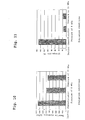
- the post-test tensile strength and elongation characteristics of the PET resin are shown in Figures 10 and 11, respectively.
- the tensile strength and elongation characteristics of the PET resin exposed to the high pressure CO 2 refrigerant are remarkably deteriorated. Additionally, it has been revealed that the tensile strength and elongation characteristics of the PET resin are scarcely deteriorated as compared to the initial characteristics when the moisture content contained in the refrigeration lubricant is adjusted to be 100 ppm or less. Needless to say, from the market achievement, it is apparent that the PET resin is not deteriorated in the R134a refrigerant, and hence the deterioration phenomenon of this resin caused by the moisture is a feature specific to the CO 2 refrigerant.
- an insulating film such as PET resin in the refrigerating cycle is deteriorated in the case where the moisture content contained in the refrigerating cycle exceeds 100 ppm, but is scarcely deteriorated when the moisture content is 100 ppm or less. Accordingly, in the present embodiment, the resin deterioration in the refrigerating cycle is not caused and the reliability can be enhanced since the moisture content entering into the refrigerating cycle can be adjusted to be 100 ppm or less by adjusting the moisture content contained in the refrigeration lubricant to be 100 ppm or less.
- FIG 4 is an enlarged schematic view of the structure of the important part of the heat transfer tube of the heat exchanger used in the refrigerating cycle apparatus in embodiment 2 of the present invention.
- the present embodiment is different from embodiment 1 in that a plurality of the thin through-holes , formed in the flat tubes 31 that are the refrigerant flowpath in the radiator and evaporator, are made to be thin holes 32 with inside grooves that are provided with a large number of small triangle-shaped grooves on the inner surface thereof.
- the outer diameter (a virtual diameter from a groove trough to the opposing groove trough) of a thin hole 32 with inside grooves is taken to be 1 mm and the groove depth is taken to be 0.1 mm.
- Polyol ester oil (POE oil) that is a polar oil is used for the refrigeration lubricant and the moisture content in the oil is adjusted to be 100 ppm or less.
- the thin through-holes that are the refrigerant flow path in the heat exchanger are made to be the thin holes 32 with inside grooves in which a large number of small triangle-shaped grooves are provided on the inner surface thereof, and hence the heat transfer area of the refrigerant flow path is increased and additionally the heat transfer coefficient of the refrigerant is improved dramatically owing to the refrigerant stirring effect provided by the minute grooves and the like.
- the polar oil when a polar oil is used, the polar oil is not hydrolyzed because the moisture content contained in the refrigeration lubricant is adjusted to be 100 ppm or less and the refrigeration lubricant is not deteriorated and thus the reliability is not failed.
- Figure 5 is an enlarged schematic view of the structure of the important part of the heat transfer tube of the heat exchanger used in the refrigerating cycle apparatus in embodiment 3 of the present invention.
- the present embodiment is different from embodiment 2 in that a plurality of the thin through-holes with inside grooves, formed in the flat tubes 41 that are the refrigerant flow path in the radiator and evaporator, are made to be thin holes 42 with inside trapezoidal grooves in which the groove shape is made to be trapezoidal.
- the outer diameter (a virtual diameter from a groove trough to the opposing groove trough) of a thin hole 42 with inside grooves is taken to be 1 mm and the groove depth is taken to be 0.1 mm, and the number of the grooves is identical to that in the case of the triangular grooves (the dotted line 43 in Figure 5) of the above described embodiment 2 , but the groove shape is made to be trapezoidal.
- polyvinyl ether oil (PVE oil) that is a polar oil is used for the refrigeration lubricant and the moisture content in the oil is adjusted to be 100 ppm or less.
- the heat transfer coefficient of the refrigerant is improved dramatically because, the thin through-holes that are the refrigerant flow path in the heat exchanger are made to be the thin holes 42 with inside grooves in which a large number of small trapezoid-shaped grooves are provided on the inner surface thereof and hence the heat transfer area of the refrigerant flow path is increased as compared to the heat transfer tube in the above described embodiment 2 which has the same groove depth and the same groove number of triangular grooves, additionally the wetted perimeter length of the refrigerant flow path is increased to decrease the hydraulic diameter, the refrigerant stirring effect and the like are provided by the minute grooves, and additionally, in the case of the circulating flow, the liquid film thickness is made to be uniform owing to the increased ability for holding the refrigerant in the grooves.
- the polar oil when a polar oil is used, the polar oil is not hydrolyzed because the moisture content contained in the refrigeration lubricant is adjusted to be 100 ppm or less and the refrigeration lubricant is not deteriorated so that the reliability is not failed.
- the refrigerant flow path in the heat exchanger for the CO 2 refrigerant is made to be a plurality of thin through-holes formed in flat tubes and the refrigeration lubricant containing a polar oil as the main component is used, so that the oil film that is to be thermal resistance and flow resistance is not formed on the tube inner wall surface of thin through-holes, and hence the degradation of the heat transfer coefficient and the increase of the pressure loss in the heat exchanger can be suppressed, which makes it possible to actualize a compact and high-performance refrigerating cycle apparatus utilizing the CO 2 refrigerant.
Landscapes
- Engineering & Computer Science (AREA)
- Physics & Mathematics (AREA)
- Thermal Sciences (AREA)
- Mechanical Engineering (AREA)
- General Engineering & Computer Science (AREA)
- Geometry (AREA)
- Lubricants (AREA)
Abstract
A refrigerating cycle apparatus including a
compressor of compressing carbon dioxide (CO2)
refrigerant, a radiator of cooling the refrigerant
pressurized by the compressor, a pressure reducing valve
that is arranged more downstream of the radiator along
the refrigerant flow and depressurizes and expands the
cooled refrigerant, and an evaporator that heats the
refrigerant depressurized by the pressure reducing valve,
wherein the refrigerant flow path of the radiator and/or
said evaporator is thin tubes of 1 mm or less; and a
refrigeration lubricant of which main component is a polar
oil miscible with the CO2 refrigerant is utilized.
Description
- The present invention relates to a refrigerating cycle apparatus such as a refrigerating machine and an air-conditioning machine using carbon dioxide (hereinafter denoted as CO2) as the main refrigerant.
- At present, fluorocarbons containing chlorine but not containing hydrogen (hereinafter denoted as CFC) and fluorinated hydrocarbons containing both chlorine and hydrogen (hereinafter denoted as HCFC) are used as the refrigerants in the refrigerating cycle apparatus in air conditioners, refrigerators, freezers, vending machines, heat pump hot water suppliers and the like because these refrigerants are stable in physical properties and easy in handling.
- The CFC and HCFC refrigerants, however, have characteristics to promote the depletion of the ozone layer, and accordingly the adoption of the fluorinated hydrocarbons which do not contain chlorine but contain hydrogen in the molecular structure (hereinafter denoted as HFC) as the alternative refrigerants has been proposed. Additionally, because the CFC, HCFC and HFC refrigerants have characteristics to promote global warming, the adoption of natural refrigerants having an extremely feeble effect on global warming as the alternative refrigerants has been proposed.
- Because among even the natural refrigerants, however, hydrocarbons (hereinafter denoted as HC) are strongly flammable so that there is the danger of catching fire and exploding, and the ammonia refrigerant is toxic so that there is a problem that a hazard possibly occurs at the time of leakage thereof, the adoption of the CO2 refrigerant which is.nonflammable, nontoxic and low in price has been considered.
- A refrigerating cycle apparatus using the CO2 refrigerant has a configuration in which the high pressure line is operated under the supercritical region because the critical temperature of the CO2 refrigerant is 31°C. A commonly used refrigerating cycle apparatus is constructed by connecting together by piping a compressor which compresses the refrigerant to elevate the pressure thereof, a four way valve according to need, a radiator which cools the refrigerant, a pressure reducing valve which reduces the pressure of the refrigerant such as a capillary tube and an expansion valve, an evaporator which evaporates and gasifies the refrigerant and the like; and the refrigerant is circulated in the interior of the apparatus to conduct cooling or heating operation.
- As the heat exchanger used in the radiator and evaporator of the refrigerating cycle apparatus using the CO2 refrigerant, a heat exchanger referred to as a microtube heat exchanger is used. A microtube heat exchanger is composed of flat tubes internally provided with a plurality of thin through-holes (the refrigerant flow path) and fins arranged between the flat tubes for the purpose of increasing the heat transfer area for the external fluid (for example, the air). The thin through-holes have a circular sectional shape and are of the order of 1 mm in hole size.
- Additionally, as the refrigeration lubricant for the CO2 refrigerant, mineral oils have been frequently used from the viewpoint of the excellent lubricity thereof (see the reference: B. E. Fagerli, "Development and Experiment with a Hermetic CO2 Compressor," Proceeding of the 1996 International Engineering Conference at Purdue, 229-234).
- Incidentally, a mineral oil is a nonpolar oil and hence immiscible with the CO2 refrigerant. The refrigeration lubricant discharged from the compressor into the cycle together with the refrigerant flows through the refrigerant flow paths in the radiator and evaporator in the form of oil drops or oil film coating the tube inner wall in a ring shape. This causes the heat transfer inhibition and the increase of the pressure loss, and becomes the cause for the dimensional enlargement and efficiency degradation of the heat exchanger. Particularly, the heat transfer degradation ascribable to the refrigeration lubricant is remarkable in the evaporator which is not operated in the supercritical region.
- Additionally, the present inventor has found that in the case of the microtube heat exchanger, the refrigerant flow path consists of very thin heat transfer tubes of the order of 1 mm in hole size, and hence the effect of the heat transfer inhibition and pressure loss due to oil films and oil drops formed on the tube inner wall is larger as compared to the refrigerant flow path having a large sectional area of a pipe diameter of the order of 5 mm as has been applied to the conventional HFC refrigerants. Detailed description will be made below on the content of the above described finding.
- Figures 6 and 7, respectively, are the graphs showing the characteristics of the evaporating ability and pressure loss in the evaporator, which has the flat tubes each consisting of microtubes having hydraulic diameter of 1.2 mm as the refrigerant flow path. As the refrigeration lubricant, a mineral oil that is a nonpolar oil immiscible with the CO2 refrigerant is used. The horizontal axis in each figure represents the oil circulation rate that is obtained by dividing the oil (refrigeration lubricant) circulation quantity by the refrigerant circulation quantity. It can be seen that in the case of an immiscible oil, the heat transfer coefficient is remarkably decreased due to the increase in the oil circulation rate and the pressure loss is remarkably increased.
- The calculated values obtained from a variety of experimental data including the data presented in Figures 6 and 7 on the basis of the correlation formulas which will be described below are in good agreement with the evaporation heat transfer coefficient and pressure loss values of the flat tubes in the case where the oil and CO2 refrigerant are circulated.
- In other words, as for the evaporation heat transfer coefficient, the Liu-Winterton correlation formula, generally known as the correlation formula for the evaporation heat transfer coefficient in the tube, has been modified using the parameter Kfh taking account of the oil mixing effect on the nucleate boiling heat transfer coefficient, while as for the forced convection heat transfer coefficient, a modification has been made in which the values of the physical properties of the liquid are replaced with the values of the mixed properties of the refrigerant and oil.
-
-
- Here, h denotes the evaporation heat transfer coefficient, a denotes a constant, hl denotes the forced convection heat transfer coefficient for the case where only the liquid phase is assumed to flow, h pool denotes the pool boiling heat transfer coefficient, and E and S, respectively, are the parameters representing the extents of the forced convection and nucleate boiling.
- Additionally, as for the pressure loss, to the Lockhart-Martinelli correlation formula generally known as the two-phase flow pressure loss correlation formula, a modification has been made in which the values of the physical properties of the liquid are replaced with the values of the mixed properties of the refrigerant and oil.
-
- Here, denotes the Martinelli parameter, ΔPf denotes the pressure loss for the case where only the liquid phase is assumed to flow, and Kfp is a correction parameter.
- Figure 8 is a characteristic diagram (a representative example) showing the evaporation heat transfer coefficient and pressure loss of the CO2 refrigerant obtained from the above described correlation formulas. The horizontal axis represents the oil circulation rate obtained by dividing the oil circulation quantity by the refrigerant circulation quantity. Besides, the vertical axis represents the quantity in percent which is obtained by dividing the ratio of heat transfer coefficient based on the value assumed to be 100 for the oil circulation rate of 0% by the ratio of pressure loss based on the value assumed to be 100 for the oil circulation rate of 0%. In other words, the ordinate value becomes 100 when the oil circulation rate is 0%, and the smaller than 100 is the ordinate value, the larger is the heat transfer coefficient depression due to the oil circulation rate increase and/or the larger is the pressure loss due to the oil circulation rate increase.
- Additionally, Figure 8 also shows the characteristics for the thin tubes with different hydraulic diameters De, and reveals that the smaller is the hydraulic diameter De, the larger is the heat transfer coefficient depression and/or the larger is the pressure loss increase.
- Thus, for the purpose of more detailed examination, Figure 9 shows the relation between the (heat transfer coefficient/pressure loss) reduction rate in relation to the oil circulation rate increase from 0% to 4% and the hydraulic diameter De. It can be seen that the (heat transfer coefficient/pressure loss) reduction rate is sharply increased when the hydraulic diameter De is decreased further from the order of 1 mm. In other words, it is shown that when the hydraulic diameter De is made further thinner than the order of 1 mm, the immiscible oil allows the oil film to be formed on the tube inner wall or the oil drops to be scattered in the interior of the tube, and hence the depression of the heat transfer coefficient becomes large and/or the increase of the pressure loss becomes large.
- A first invention of the present invention is a refrigerating cycle apparatus, comprising a compressor of compressing carbon dioxide (CO2) refrigerant, a radiator of cooling the refrigerant pressurized by said compressor, a pressure reducing valve that is arranged more downstream of said radiator along the refrigerant flow and depressurizes and expands the cooled refrigerant, and an evaporator that heats the refrigerant depressurized by said pressure reducing valve,
wherein the refrigerant flow path of said radiator and/or said evaporator is thin tubes of 1 mm or less; and - Refrigeration lubricant of which main component is a polar oil miscible with said CO2 refrigerant is utilized.
- A second invention of the present invention is the refrigerating cycle apparatus according to the first invention of the present invention, wherein said refrigerant flow path is a plurality of thin through-holes formed in flat tubes.
- A third invention of the present invention is the refrigerating cycle apparatus according to the first invention of the present invention, wherein an ester oil, an ether oil, polyalkyleneglycol oil, polycarbonate oil, or a mixed oil thereof is used as said refrigeration lubricant.
- A fourth invention of the present invention is the refrigerating cycle apparatus according to the first invention of the present invention, wherein the moisture content contained in said refrigeration lubricant is 100 ppm or less.
- A fifth invention of the present invention is the refrigerating cycle apparatus according to the second invention of the present invention, wherein said thin through-holes are thin holes with inside grooves in which grooves are formed on the inner surface.
- A sixth invention of the present invention is the refrigerating cycle apparatus according to the fifth invention of the present invention, wherein the groove shape of said through-holes with inside grooves is trapezoidal.
- The present invention solves such problems found in the conventional refrigerating cycles as described above and takes as its object the provision of a compact refrigerating cycle apparatus with high efficiency using the CO2 refrigerant.
-
- Figure 1 is a schematic block diagram showing the
refrigerating cycle apparatus in an
embodiment 1 of the present invention; - Figure 2 is a schematic view showing the structure
of a heat exchanger used in the
embodiment 1 of the present invention; - Figure 3 is a schematic view showing the structure
of a heat transfer tube used in the heat exchanger in
the
embodiment 1 of the present invention; - Figure 4 is an enlarged schematic view of the structure
of the important part of the heat transfer tube of the
heat exchanger used in the refrigerating cycle apparatus
in an
embodiment 2 of the present invention; - Figure 5 is an enlarged schematic view of the structure
of the important part of the heat transfer tube of the
heat exchanger used in the refrigerating cycle apparatus
in an
embodiment 3 of the present invention; - Figure 6 is a graph showing the characteristics of the evaporation ability against the oil circulation rate in the evaporator, which has flat tubes in which microtubes of 1.2 mm in hydraulic diameter are used as the refrigerant flow path;
- Figure 7 a graph showing the characteristics of the pressure loss against the oil circulation rate in the evaporator utilizing flat tubes in which microtubes of 1.2 mm in hydraulic diameter are used as the refrigerant flow path;
- Figure 8 is a graph showing the characteristics of the thin tubes different in the hydraulic diameter De;
- Figure 9 is a graph showing the relation between the (heat transfer coefficient/pressure loss) reduction rate and the hydraulic diameter De for the case where the oil circulation rate is increased from 0% to 4%;
- Figure 10 is a graph showing the tensile strength characteristic diagram of PET resin after the test when an autoclave test has been performed; and
- Figure 11 is a graph showing the elongation characteristic diagram of PET resin after the test when an autoclave test has been performed.
-
-
- 1, 31, 41
- Flat tube
- 2
- Thin through-hole
- 3
- Heat exchanger
- 9
- Fin
- 11
- Compressor
- 12
- Radiator
- 13
- Pressure reducing valve
- 14
- Evaporator
- 15
- Oil separator
- 16
- Auxiliary heat exchanger
- 17
- Sub pressure reducing valve
- 32, 42
- Thin hole with inside grooves
- Description will be made below on the embodiments of the present invention with reference to the accompanying drawings.
- Figure 1 shows a schematic block diagram showing the refrigerating cycle apparatus in an
embodiment 1 of the present invention. Figure 2 is a schematic view showing the structure of a heat exchanger used in the radiator and evaporator, and Figure 3 is a schematic view showing the structure of the heat transfer tube used in the above described heat exchanger. - In Figures 1 to 3,
reference numeral 11 denotes a compressor, 12 denotes a radiator having a plurality of thin through-holes 2 formed in theflat tube 1 as the refrigerant flow path, 13 denotes a pressure reducing valve, and 14 denotes an evaporator having a plurality of thin' through-holes 2 formed in theflat tubes 1 as the refrigerant flow path; these are connected together by piping to form a closed loop that constitutes a refrigerating cycle in which the CO2 refrigerant is circulated along the direction of the arrows written in the figure. - Furthermore, an
auxiliary heat exchanger 16 is arranged to perform heat exchange between the refrigerant flow path in the heat release section that is the refrigerant flow path falling in the range from the outlet of theradiator 12 to the inlet of thepressure reducing valve 13 and the refrigerant flow path in the evaporation section that is the refrigerant flow path falling in the range from the outlet of theevaporator 14 to the suction part of thecompressor 11. - Additionally, an
oil separator 15 is arranged between thecompressor 11 and theradiator 12. Here is a configuration in which the refrigeration lubricant separated in theoil separator 15 is made to return to thecompressor 11 through the intermediary of a subpressure reducing valve 17 along anauxiliary path 18 connected by piping to thecompressor 11. Incidentally, the part of the refrigeration lubricant that has not been separated in theoil separator 15 comes to flow together with the refrigerant in theradiator 12 and theevaporator 14 in the refrigerating cycle. - Additionally, as Figures 2 and 3 show, the
heat exchanger 3 used in the radiator and evaporator has a configuration in which a plurality of the plate-like flat tubes 1 (heat transfer tubes) , each having a plurality of thin through-holes 2 penetrated in the lengthwise direction, are laminated in the thickness direction of the plate shape approximately with the predetermined intervals, and both lengthwise ends of the plate shape are inserted into a pair ofheader pipes holes 2 is made to be as small as about 1 mm, and additionally the sectional shape thereof is made to be circular. - Additionally, in the pair of the
header pipes partition plates 6 that partition the interior of each header pipe into a plurality of partitions along the lengthwise direction. Additionally, arefrigerant inlet 7 for introducing the refrigerant into theheat exchanger 3 is arranged on either of the pair of theheader pipes refrigerant outlet 8 for discharging the refrigerator from theheat exchanger 3 is arranged on either of the pair of theheader pipes flat tubes 1 are arranged along the thickness direction approximately at even intervals, and fins 9 (wavy fins) are arranged between theflat tubes 1 for the purpose of enlarging the area for heat transfer to the external fluid (for example, the air). - Besides, the CO2 refrigerant is used as the refrigerant and polyalkyleneglycol oil (PAG oil) that is a polar oil is used as the refrigeration lubricant, the moisture content of which is adjusted to be 100 ppm or lower.
- In the next place, description will be made below on the operation of the refrigerating cycle apparatus that has such a configuration as described above.
- The CO2 refrigerant compressed in the·
compressor 11 takes a high temperature and high pressure state, and is introduced into theradiator 12. In theradiator 12, the CO2 refrigerant does not take the gas/liquid two phase state when the CO2 refrigerant flows in the supercritical state, releases the heat to the media including the air and water, and is further cooled in the refrigerant flow path of theauxiliary heat exchanger 16 in the heat release section, which is from the outlet of theradiator 12 to the inlet of thepressure reducing valve 13. The CO2 refrigerant is depressurized in thepressure reducing valve 13 to take a low-pressure gas/liquid two-phase state, and is introduced into theevaporator 14. In theevaporator 14, the CO2 refrigerant absorbs the heat from the air and the like, and takes a gaseous state in the refrigerant flow path of theauxiliary heat exchanger 16 in the evaporation part, which is from the outlet of theevaporator 14 to the suction part of thecompressor 11, and is again sucked into thecompressor 11. - Through repeating such a cycle as described above, the heating action is made in the
radiator 12 by heat release and the cooling action is made in theevaporator 14 by heat absorption. In this connection, in theauxiliary heat exchanger 16, heat exchange occurs between the relatively high temperature CO2 refrigerant leaving theradiator 12 and going to thepressure reducing valve 13 and the relatively low temperature CO2 refrigerant leaving theevaporator 14 and going to thecompressor 11. Accordingly, the CO2 refrigerant having left theradiator 12 is further cooled and then depressurized in thepressure reducing valve 13, and hence the enthalpy is decreased at the inlet of theevaporator 14 to increase the enthalpy difference between the inlet and outlet of theevaporator 14, and the endothermic ability (cooling capacity) is thereby increased. - Furthermore, detailed description will be made below on the operation of the
heat exchanger 3 acting as theradiator 12. As shown by the arrows in Figure 2, the refrigerant in the supercritical state flows through therefrigerant inlet 7 into the space above thepartition plate 6 in theheader pipe 4, (1) flows into the upper portion of theheader pipe 5 through the thin through-holes 2 in the plurality of theflat tubes 1 inserted into the portion above thepartition plate 6 in theheader pipe 4, (2) flows through from the upper portion to the middle portion (the space above the partition plate 6) of theheader pipe 5, (3) flows in through the thin through-holes 2 in theflat tubes 1 into the middle portion of theheader pipe 4, (4) flows through from the middle portion to the bottom portion of theheader pipe 4, and (5) flows in through the thin through-holes 2 in theflat tubes 1 into the bottom portion (the space beneath the partition plate 6) of theheader pipe 5 and flows out from therefrigerant outlet 8 at a low temperature. - In the present embodiment, polyalkyleneglycol oil (PAG oil) that is a polar oil is used so that the refrigeration lubricant discharged from the compressor together with the CO2 refrigerant into the cycle is miscible in the CO2 refrigerant. Consequently, even when the refrigerant flow path, which is thin tubes of 1 mm or less, no oil film that is to be thermal resistance is formed on the inside wall surface of the thin through-
holes 2 of theflat tubes 1 constituting the refrigerant flow path of the radiator, and hence no degradation of the heat transfer performance occurs so that it is possible to effectively take advantage of the high heat transfer coefficient that is possessed by the CO2 refrigerant in the supercritical state. Additionally, because no oil film is formed on the inside wall surface of the thin through-holes 2 and no oil flows as oil drops, no increase of the pressure loss is brought on. Consequently, the intratube heat transfer rate is very high and the performance degradation caused by pressure loss can be suppressed, which makes it possible to make the radiator compact and high in performance. - In the case of the evaporator, the CO2 refrigerant taking the low-pressure gas /liquid two-phase state flows, together with the refrigeration lubricant, into the thin through-
holes 2 of theflat tubes 1 constituting the refrigerant flow path in the evaporator, and flows therein as annular mist flow while being evaporated by absorbing heat from the air and the like. Accordingly, the heat transfer coefficient on the inside wall surface of the heat transfer tube significantly affects the overall performance; in the present embodiment, similarly to the case of the radiator, polyalkyleneglycol oil (PAG oil) that is miscible in the CO2 refrigerant is used, and hence no oil film that is to be thermal resistance is formed on the tube inner wall surface of the thin through-holes 2 of theflat tubes 1 even when the refrigerant flow path is formed using thin tubes of 1 mm or less. Consequently, neither degradation of the heat transfer nor increase of the pressure loss is brought on in the evaporator, which makes it possible to make the evaporator compact and high in efficiency. - Incidentally, in the above explanation, description has been made on the basis of polyalkyleneglycol oil (PAG oil) as a polar oil; even when another oil such as polyol ester oil, polyvinyl ether oil, polycarbonate oil, or mixed oil thereof is used as a polar oil, similar effects can be obtained because these oils are high in miscibility in the CO2 refrigerant.
- Additionally, in the present embodiment, when a polar oil is used, the polar oil is not hydrolyzed because the moisture content contained in the refrigeration lubricant is adjusted to be 100 ppm or less and the refrigeration lubricant is not deteriorated and thus the reliability is not failed.
- Additionally, the adj ustment of the moisture content contained in the refrigeration lubricant to 100 ppm or less makes it possible to adjust the content of the moisture entering into the refrigerating cycle to be 100 ppm or less, and accordingly the effects described below occur.
- The present inventor has confirmed the novel facts and effects obtained by the above described means on the basis of the experiments described below. The CO2 refrigerant, PET (polyethylene terephthalate) resin film and the refrigeration lubricant containing the moisture content of 200 ppm were sealed in an autoclave container, and the autoclave test for the test time period of 500 hours was performed at 140°C and at the pressures of 8 MPa and 11 MPa. The PET resin is a commercially time-proven resin as an insulating film in compressors for the refrigerant R134a. The post-test tensile strength and elongation characteristics of the PET resin are shown in Figures 10 and 11, respectively. It can be seen that as compared with the pre-test initial characteristics, the tensile strength and elongation characteristics of the PET resin exposed to the high pressure CO2 refrigerant are remarkably deteriorated. Additionally, it has been revealed that the tensile strength and elongation characteristics of the PET resin are scarcely deteriorated as compared to the initial characteristics when the moisture content contained in the refrigeration lubricant is adjusted to be 100 ppm or less. Needless to say, from the market achievement, it is apparent that the PET resin is not deteriorated in the R134a refrigerant, and hence the deterioration phenomenon of this resin caused by the moisture is a feature specific to the CO2 refrigerant.
- From the above experimental results, it has been revealed that an insulating film such as PET resin in the refrigerating cycle is deteriorated in the case where the moisture content contained in the refrigerating cycle exceeds 100 ppm, but is scarcely deteriorated when the moisture content is 100 ppm or less. Accordingly, in the present embodiment, the resin deterioration in the refrigerating cycle is not caused and the reliability can be enhanced since the moisture content entering into the refrigerating cycle can be adjusted to be 100 ppm or less by adjusting the moisture content contained in the refrigeration lubricant to be 100 ppm or less.
- Additionally, in the present embodiment, description has been developed on the basis of the refrigerating cycle provided with an
oil separator 15, but it is obvious that the present invention displays the effect thereof particularly for the case where anoil separator 15 is absent since the present invention utilizes a polar oil soluble in the refrigerant. - Description will be made below on the refrigerating cycle apparatus in
embodiment 2 of the present invention with reference to the accompanying drawing. - Figure 4 is an enlarged schematic view of the structure of the important part of the heat transfer tube of the heat exchanger used in the refrigerating cycle apparatus in
embodiment 2 of the present invention. The present embodiment is different fromembodiment 1 in that a plurality of the thin through-holes , formed in the flat tubes 31 that are the refrigerant flowpath in the radiator and evaporator, are made to bethin holes 32 with inside grooves that are provided with a large number of small triangle-shaped grooves on the inner surface thereof. The outer diameter (a virtual diameter from a groove trough to the opposing groove trough) of athin hole 32 with inside grooves is taken to be 1 mm and the groove depth is taken to be 0.1 mm. Polyol ester oil (POE oil) that is a polar oil is used for the refrigeration lubricant and the moisture content in the oil is adjusted to be 100 ppm or less. - In this way, the thin through-holes that are the refrigerant flow path in the heat exchanger are made to be the
thin holes 32 with inside grooves in which a large number of small triangle-shaped grooves are provided on the inner surface thereof, and hence the heat transfer area of the refrigerant flow path is increased and additionally the heat transfer coefficient of the refrigerant is improved dramatically owing to the refrigerant stirring effect provided by the minute grooves and the like. - Incidentally, in the present embodiment, since polyol ester oil (POE oil) that is a polar oil is used, the refrigeration lubricant discharged from the compressor into the cycle together with the CO2 refrigerant is miscible in the CO2 refrigerant. Consequently, the oil film that is to be thermal resistance is not formed on the tube inner wall surface of the
thin holes 32 with inside grooves in the flat tubes 31 constituting the refrigerant flow path of the radiator and evaporator so that the heat transfer is not degraded, and hence the high heat transfer coefficient that is possessed by the CO2 refrigerant can be effectively utilized. - Additionally, no oil film is formed on the tube inner wall surface of the
thin holes 32 with inside grooves, and additionally no oil flows as oil drops so that no increase in pressure loss is brought on. Accordingly, the heat transfer coefficient in the tubes is very high and the performance degradation due to the pressure loss can be suppressed, which makes it possible to make the heat exchanger compact and high in performance. - Incidentally, in the above explanation, description has been developed on the basis of the polyol ester oil (POE oil) used as the polar oil; however, similar effects can be obtained even when other polar oils are used because the polar solvents are high in miscibility in the CO2 refrigerant.
- Additionally, in the present embodiment, when a polar oil is used, the polar oil is not hydrolyzed because the moisture content contained in the refrigeration lubricant is adjusted to be 100 ppm or less and the refrigeration lubricant is not deteriorated and thus the reliability is not failed.
- Description will be made below on the refrigerating cycle apparatus in
embodiment 3 of the present invention with reference to the accompanying drawing. - Figure 5 is an enlarged schematic view of the structure of the important part of the heat transfer tube of the heat exchanger used in the refrigerating cycle apparatus in
embodiment 3 of the present invention. The present embodiment is different fromembodiment 2 in that a plurality of the thin through-holes with inside grooves, formed in the flat tubes 41 that are the refrigerant flow path in the radiator and evaporator, are made to bethin holes 42 with inside trapezoidal grooves in which the groove shape is made to be trapezoidal. Incidentally, the outer diameter (a virtual diameter from a groove trough to the opposing groove trough) of athin hole 42 with inside grooves is taken to be 1 mm and the groove depth is taken to be 0.1 mm, and the number of the grooves is identical to that in the case of the triangular grooves (the dottedline 43 in Figure 5) of the above describedembodiment 2 , but the groove shape is made to be trapezoidal. Besides, polyvinyl ether oil (PVE oil) , that is a polar oil is used for the refrigeration lubricant and the moisture content in the oil is adjusted to be 100 ppm or less. - As described above, the heat transfer coefficient of the refrigerant is improved dramatically because, the thin through-holes that are the refrigerant flow path in the heat exchanger are made to be the
thin holes 42 with inside grooves in which a large number of small trapezoid-shaped grooves are provided on the inner surface thereof and hence the heat transfer area of the refrigerant flow path is increased as compared to the heat transfer tube in the above describedembodiment 2 which has the same groove depth and the same groove number of triangular grooves, additionally the wetted perimeter length of the refrigerant flow path is increased to decrease the hydraulic diameter, the refrigerant stirring effect and the like are provided by the minute grooves, and additionally, in the case of the circulating flow, the liquid film thickness is made to be uniform owing to the increased ability for holding the refrigerant in the grooves. Incidentally, a high heat transfer coefficient can be achieved in the above describedembodiment 2, but there is a possibility that the presence of the grooves therein promotes the oil film formation; however, it can be said that in thepresent embodiment 3, the groves are trapezoidal and hence the oil film formation can be more suppressed. - Incidentally, in the present embodiment, since polyvinyl ether oil (PVE oil) that is a polar oil is used, the refrigeration lubricant discharged from the compressor into the cycle together with the CO2 refrigerant is miscible in the CO2 refrigerant. Consequently, the oil film that is to be thermal resistance is not formed on the tube inner wall surface of the
thin holes 42 with inside grooves in the flat tubes 41 constituting the refrigerant flow path of the radiator and evaporator so that the heat transfer is not degraded, and hence the high heat transfer coefficient that is possessed by the CO2 refrigerant can be effectively utilized. - Additionally, no oil film is formed on the tube inner wall surface of the
thin holes 42 with inside grooves, and additionally no oil flows as oil drops so that increase in no pressure loss is brought on. Accordingly, the heat transfer coefficient in the tubes is very high and the performance degradation due to the pressure loss can be suppressed, which makes it possible to make the heat exchanger compact and high in performance. - Incidentally, in the above explanation, description has been developed on the basis of the polyvinyl ether oil (PVE oil) used as the polar oil; however, similar effects can be obtained even when other polar oils are used because the polar solvents are high in miscibility in the CO2 refrigerant.
- Additionally, in the present embodiment, when a polar oil is used, the polar oil is not hydrolyzed because the moisture content contained in the refrigeration lubricant is adjusted to be 100 ppm or less and the refrigeration lubricant is not deteriorated so that the reliability is not failed.
- As can be clearly seen from the above description, according to the present invention, the refrigerant flow path in the heat exchanger for the CO2 refrigerant is made to be a plurality of thin through-holes formed in flat tubes and the refrigeration lubricant containing a polar oil as the main component is used, so that the oil film that is to be thermal resistance and flow resistance is not formed on the tube inner wall surface of thin through-holes, and hence the degradation of the heat transfer coefficient and the increase of the pressure loss in the heat exchanger can be suppressed, which makes it possible to actualize a compact and high-performance refrigerating cycle apparatus utilizing the CO2 refrigerant.
Claims (6)
- A refrigerating cycle apparatus, comprising a compressor of compressing carbon dioxide (CO2) refrigerant, a radiator of cooling the refrigerant pressurized by said compressor, a pressure reducing valve that is arranged more downstream of said radiator along the refrigerant flow and depressurizes and expands the cooled refrigerant, and an evaporator that heats the refrigerant depressurized by said pressure reducing valve,
wherein the refrigerant flow path of said radiator and/or said evaporator is thin tubes of 1 mm or less; and
Refrigeration lubricant of which main component is a polar oil miscible with said CO2 refrigerant is utilized. - The refrigerating cycle apparatus according to claim 1, wherein said refrigerant flow path is a plurality of thin through-holes formed in flat tubes.
- The refrigerating cycle apparatus according to claim 1, wherein an ester oil, an ether oil, polyalkyleneglycol oil, polycarbonate oil, or a mixed oil thereof is used as said refrigeration lubricant.
- The refrigerating cycle apparatus according to claim 1, wherein the moisture content contained in said refrigeration lubricant is 100 ppm or less.
- The refrigerating cycle apparatus according to claim 2, wherein said thin through-holes are thin holes with inside grooves in which grooves are formed on the inner surface.
- The refrigerating cycle apparatus according to claim 5, wherein the groove shape of said through-holes with inside grooves is trapezoidal.
Applications Claiming Priority (3)
| Application Number | Priority Date | Filing Date | Title |
|---|---|---|---|
| JP2001153508 | 2001-05-23 | ||
| JP2001153508 | 2001-05-23 | ||
| PCT/JP2002/004904 WO2002095302A1 (en) | 2001-05-23 | 2002-05-21 | Refrigerating cycle device |
Publications (1)
| Publication Number | Publication Date |
|---|---|
| EP1389721A1 true EP1389721A1 (en) | 2004-02-18 |
Family
ID=18998013
Family Applications (1)
| Application Number | Title | Priority Date | Filing Date |
|---|---|---|---|
| EP02728095A Withdrawn EP1389721A1 (en) | 2001-05-23 | 2002-05-21 | Refrigerating cycle device |
Country Status (6)
| Country | Link |
|---|---|
| US (1) | US20040206109A1 (en) |
| EP (1) | EP1389721A1 (en) |
| JP (1) | JPWO2002095302A1 (en) |
| KR (1) | KR20040036874A (en) |
| CN (1) | CN1526061A (en) |
| WO (1) | WO2002095302A1 (en) |
Cited By (3)
| Publication number | Priority date | Publication date | Assignee | Title |
|---|---|---|---|---|
| FR2890435A1 (en) * | 2005-09-07 | 2007-03-09 | Commissariat Energie Atomique | HEAT EXCHANGER COMPRISING A SUPERCRITICAL CARBON DIOXIDE CIRCUIT |
| WO2013003375A1 (en) * | 2011-06-27 | 2013-01-03 | Carrier Corporation | Micro-port shell and tube heat exchanger |
| EP2077429A4 (en) * | 2006-10-18 | 2014-05-07 | Daikin Ind Ltd | HEAT EXCHANGER AND REFRIGERATION DEVICE |
Families Citing this family (22)
| Publication number | Priority date | Publication date | Assignee | Title |
|---|---|---|---|---|
| JP4196774B2 (en) * | 2003-07-29 | 2008-12-17 | 株式会社デンソー | Internal heat exchanger |
| WO2006068664A2 (en) * | 2004-07-13 | 2006-06-29 | Tiax Llc | System and method of refrigeration |
| JP2006090657A (en) * | 2004-09-24 | 2006-04-06 | Furukawa Electric Co Ltd:The | Heat exchanger tube for heat exchanger and manufacturing method thereof |
| DE112005003260T5 (en) * | 2004-12-24 | 2008-01-03 | Showa Denko K.K. | heat exchangers |
| US20080184734A1 (en) * | 2005-03-18 | 2008-08-07 | Carrier Commercial Refrigeration, Inc. | Flat Tube Single Serpentine Co2 Heat Exchanger |
| DE102005016540A1 (en) * | 2005-04-08 | 2006-10-12 | Behr Gmbh & Co. Kg | Multichannel flat tube |
| FR2895786B1 (en) * | 2006-01-04 | 2008-04-11 | Valeo Systemes Thermiques | RELAXATION MODULE FOR AIR CONDITIONING INSTALLATION WITH TWO EVAPORATORS |
| JP2008020166A (en) * | 2006-07-14 | 2008-01-31 | Kobelco & Materials Copper Tube Inc | Inner surface grooved heat-transfer tube for evaporator |
| US7631511B2 (en) * | 2006-08-08 | 2009-12-15 | Eid Al-Azmi | Portable air conditioning and water cooling apparatus |
| JP2012073028A (en) * | 2006-10-18 | 2012-04-12 | Daikin Industries Ltd | Heat exchanger |
| JP5143461B2 (en) * | 2007-03-27 | 2013-02-13 | Jx日鉱日石エネルギー株式会社 | Refrigerating machine oil for carbon dioxide refrigerant and working fluid composition for refrigerator. |
| JP2010002099A (en) * | 2008-06-19 | 2010-01-07 | Mitsubishi Electric Corp | Refrigerating cycle device |
| CN102575890B (en) * | 2009-11-03 | 2015-08-26 | 开利公司 | Pressure spike in conjunction with the refrigerant system of micro channel heat exchanger reduces |
| JP5784215B2 (en) * | 2012-03-07 | 2015-09-24 | 三菱電機株式会社 | Heat exchanger and refrigeration cycle equipment |
| US20150068707A1 (en) * | 2013-09-09 | 2015-03-12 | Nec Corporation | Electronic component cooling apparatus |
| JP5999081B2 (en) * | 2013-12-24 | 2016-09-28 | 株式会社豊田中央研究所 | Cooled element and selective deposition method |
| US10473226B2 (en) * | 2017-06-12 | 2019-11-12 | Hamilton Sundstrand Corporation | Heat exchanger valves |
| US11725889B1 (en) * | 2019-02-26 | 2023-08-15 | National Technology & Engineering Solutions Of Sandia, Llc | Refractory high entropy alloy compact heat exchanger |
| JPWO2020240858A1 (en) * | 2019-05-31 | 2020-12-03 | ||
| PL240519B1 (en) * | 2020-01-31 | 2022-04-19 | Dac Spolka Z Ograniczona Odpowiedzialnoscia | Cooling unit with dynamic air cooling and the working element of the unit |
| US11519670B2 (en) | 2020-02-11 | 2022-12-06 | Airborne ECS, LLC | Microtube heat exchanger devices, systems and methods |
| US12416453B1 (en) | 2021-07-22 | 2025-09-16 | Intergalactic Spaceworx, LLC | Heat exchange header with refrigerant distribution by capillary wicking porous insert |
Family Cites Families (6)
| Publication number | Priority date | Publication date | Assignee | Title |
|---|---|---|---|---|
| JP3573640B2 (en) * | 1998-03-04 | 2004-10-06 | 株式会社神戸製鋼所 | Boiling heat transfer tube |
| JP2000073951A (en) * | 1998-08-31 | 2000-03-07 | Mitsubishi Electric Corp | Refrigerant compressor and refrigeration cycle using the refrigerant compressor |
| JP2000193389A (en) * | 1998-12-28 | 2000-07-14 | Hitachi Ltd | Outdoor unit of air conditioner |
| JP2001133075A (en) * | 1999-11-09 | 2001-05-18 | Sanden Corp | Heat exchanger in refrigerating circuit |
| JP2001330388A (en) * | 2000-05-19 | 2001-11-30 | Matsushita Electric Ind Co Ltd | Heat exchanger unit |
| JP2002188872A (en) * | 2000-12-20 | 2002-07-05 | Matsushita Electric Ind Co Ltd | Refrigeration cycle device |
-
2002
- 2002-05-21 JP JP2002591734A patent/JPWO2002095302A1/en active Pending
- 2002-05-21 KR KR10-2003-7015148A patent/KR20040036874A/en not_active Abandoned
- 2002-05-21 US US10/476,040 patent/US20040206109A1/en not_active Abandoned
- 2002-05-21 CN CNA028100395A patent/CN1526061A/en not_active Withdrawn
- 2002-05-21 EP EP02728095A patent/EP1389721A1/en not_active Withdrawn
- 2002-05-21 WO PCT/JP2002/004904 patent/WO2002095302A1/en not_active Ceased
Non-Patent Citations (1)
| Title |
|---|
| See references of WO02095302A1 * |
Cited By (6)
| Publication number | Priority date | Publication date | Assignee | Title |
|---|---|---|---|---|
| FR2890435A1 (en) * | 2005-09-07 | 2007-03-09 | Commissariat Energie Atomique | HEAT EXCHANGER COMPRISING A SUPERCRITICAL CARBON DIOXIDE CIRCUIT |
| EP1762809A1 (en) * | 2005-09-07 | 2007-03-14 | Commissariat A L'energie Atomique | Heat exchanger comprising a circuit of supercritical carbon dioxide |
| US7267161B2 (en) | 2005-09-07 | 2007-09-11 | Commissariat A L'energie Atomique | Heat exchanger comprising a supercritical carbon-dioxide circuit |
| EP2077429A4 (en) * | 2006-10-18 | 2014-05-07 | Daikin Ind Ltd | HEAT EXCHANGER AND REFRIGERATION DEVICE |
| WO2013003375A1 (en) * | 2011-06-27 | 2013-01-03 | Carrier Corporation | Micro-port shell and tube heat exchanger |
| US9777964B2 (en) | 2011-06-27 | 2017-10-03 | Carrier Corporation | Micro-port shell and tube heat exchanger |
Also Published As
| Publication number | Publication date |
|---|---|
| WO2002095302A1 (en) | 2002-11-28 |
| CN1526061A (en) | 2004-09-01 |
| US20040206109A1 (en) | 2004-10-21 |
| JPWO2002095302A1 (en) | 2004-09-09 |
| KR20040036874A (en) | 2004-05-03 |
Similar Documents
| Publication | Publication Date | Title |
|---|---|---|
| EP1389721A1 (en) | Refrigerating cycle device | |
| US6962059B2 (en) | Refrigerating cycle device | |
| JP5346815B2 (en) | Fluorinated compositions and systems using such compositions | |
| WO2019124361A1 (en) | Refrigeration cycle device | |
| US6871511B2 (en) | Refrigeration-cycle equipment | |
| JP2011002217A (en) | Refrigerating device and air conditioning apparatus | |
| JP2011112327A (en) | Air conditioner and refrigerating device | |
| Kumar et al. | Recent progress in pool boiling heat transfer of low GWP refrigerants with the effect of POE lubricant oil | |
| Carrillo et al. | Experimental performance analysis of a novel ultra-low charge ammonia air condensed chiller | |
| EP2578966A1 (en) | Refrigeration device and cooling and heating device | |
| AU766849B2 (en) | Refrigerating device | |
| CN103765131A (en) | Heat exchanger and air conditioner provided with same | |
| JP2001343173A (en) | Refrigeration cycle device for CO2 refrigerant | |
| Fernando et al. | The solubility of propane (R290) with commonly used compressor lubrication oils | |
| CN104567139A (en) | Refrigeration cycle device and air conditioning device | |
| Sarkar | Transcritical carbon dioxide heat pumps for simultaneous cooling and heating | |
| JP2008215748A (en) | Air conditioner | |
| RU2843586C1 (en) | Coolant composition (versions) | |
| Primal et al. | Refrigeration systems with minimized refrigerant charge: system design and performance | |
| Yao et al. | Effect of lubricating oil on refrigerant distribution in microchannel heat exchangers: A Review | |
| JP2011158177A (en) | Refrigeration cycle apparatus | |
| CN101611113A (en) | Fluorinated compositions and systems using such compositions | |
| JP4867569B2 (en) | Heat exchanger and refrigeration air conditioner | |
| JP2011252638A (en) | Air conditioner | |
| JPH08303882A (en) | Method of operating heat pump using new alternative refrigerant gas hfc |
Legal Events
| Date | Code | Title | Description |
|---|---|---|---|
| PUAI | Public reference made under article 153(3) epc to a published international application that has entered the european phase |
Free format text: ORIGINAL CODE: 0009012 |
|
| 17P | Request for examination filed |
Effective date: 20031121 |
|
| AK | Designated contracting states |
Kind code of ref document: A1 Designated state(s): AT BE CH CY DE DK ES FI FR GB GR IE IT LI LU MC NL PT SE TR |
|
| STAA | Information on the status of an ep patent application or granted ep patent |
Free format text: STATUS: THE APPLICATION HAS BEEN WITHDRAWN |
|
| 18W | Application withdrawn |
Effective date: 20050426 |