EP1389497A1 - HYDROFORM PROCESS, AND HYDROFORM PRODUCT FORMED BY THE PROCESS - Google Patents
HYDROFORM PROCESS, AND HYDROFORM PRODUCT FORMED BY THE PROCESS Download PDFInfo
- Publication number
- EP1389497A1 EP1389497A1 EP02771708A EP02771708A EP1389497A1 EP 1389497 A1 EP1389497 A1 EP 1389497A1 EP 02771708 A EP02771708 A EP 02771708A EP 02771708 A EP02771708 A EP 02771708A EP 1389497 A1 EP1389497 A1 EP 1389497A1
- Authority
- EP
- European Patent Office
- Prior art keywords
- steel pipe
- original tube
- tube member
- assisting member
- outer peripheral
- Prior art date
- Legal status (The legal status is an assumption and is not a legal conclusion. Google has not performed a legal analysis and makes no representation as to the accuracy of the status listed.)
- Withdrawn
Links
Images



Classifications
-
- B—PERFORMING OPERATIONS; TRANSPORTING
- B21—MECHANICAL METAL-WORKING WITHOUT ESSENTIALLY REMOVING MATERIAL; PUNCHING METAL
- B21D—WORKING OR PROCESSING OF SHEET METAL OR METAL TUBES, RODS OR PROFILES WITHOUT ESSENTIALLY REMOVING MATERIAL; PUNCHING METAL
- B21D53/00—Making other particular articles
- B21D53/88—Making other particular articles other parts for vehicles, e.g. cowlings, mudguards
-
- B—PERFORMING OPERATIONS; TRANSPORTING
- B21—MECHANICAL METAL-WORKING WITHOUT ESSENTIALLY REMOVING MATERIAL; PUNCHING METAL
- B21D—WORKING OR PROCESSING OF SHEET METAL OR METAL TUBES, RODS OR PROFILES WITHOUT ESSENTIALLY REMOVING MATERIAL; PUNCHING METAL
- B21D26/00—Shaping without cutting otherwise than using rigid devices or tools or yieldable or resilient pads, i.e. applying fluid pressure or magnetic forces
- B21D26/02—Shaping without cutting otherwise than using rigid devices or tools or yieldable or resilient pads, i.e. applying fluid pressure or magnetic forces by applying fluid pressure
- B21D26/033—Deforming tubular bodies
-
- B—PERFORMING OPERATIONS; TRANSPORTING
- B21—MECHANICAL METAL-WORKING WITHOUT ESSENTIALLY REMOVING MATERIAL; PUNCHING METAL
- B21D—WORKING OR PROCESSING OF SHEET METAL OR METAL TUBES, RODS OR PROFILES WITHOUT ESSENTIALLY REMOVING MATERIAL; PUNCHING METAL
- B21D26/00—Shaping without cutting otherwise than using rigid devices or tools or yieldable or resilient pads, i.e. applying fluid pressure or magnetic forces
- B21D26/02—Shaping without cutting otherwise than using rigid devices or tools or yieldable or resilient pads, i.e. applying fluid pressure or magnetic forces by applying fluid pressure
- B21D26/033—Deforming tubular bodies
- B21D26/051—Deforming double-walled bodies
Definitions
- the present invention relates to a hydroform process for forming an original tube member, using a die having portions to be brought into contact with the outer peripheral surface of the original tube member, and also relates to a hydroform product obtained by the hydroform process.
- a die assembly 5 shown in FIG. 5A comprises an upper die 2 having a lower surface serving as a molding surface 1, and a lower mold 4 having an upper surface serving as a molding surface 3.
- An original tube member, such as a steel pipe 6, is placed in the die assembly 5.
- a pressurized liquid e.g. water
- a pressurized liquid e.g. water
- the steel pipe 6 is expanded in a width direction.
- the expanded pipe 6 is pressed against the molding surfaces 1 and 3 of the die assembly 5.
- the reinforcing member 7 having the closed cross section as shown in FIG. 5C is formed.
- the reinforcing member 7, which has a closed section obtained by hydroforming the steel pipe 6, has a peripheral continuous wall. This peripheral wall is hardened by the work hardening effect resulting from circumferential extension of the wall. As a result, the reinforcing member 7 is characterized in that it has a thin wall thickness and a high rigidity.
- the shape of the reinforcing member 7 may be complicated by comprising indents and/or protrusions in the section, as shown in FIG. 5C, as required.
- dies of certain sectional shapes may interrupt the expansion of the steel pipe 6, since only parts of the dies are brought into contact with the outer peripheral surface of the steel pipe 6 during a hydroform process.
- the die assembly 5 shown in FIG. 5A and 5B has a molding surface 3 in the form of a trapezoidal recess.
- the other molding surface 1 has an indent 1a, projection 1b, stepped portion 1c, etc.
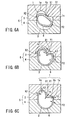
- some parts of the steel pipe 6 are brought into contact with the molding surfaces 1 and 3 before other parts, as shown in FIG. 6A.
- a first corner portion X1 near the tip of the projection 1b of the inner surface of the die assembly 5, an inner surface X2 opposing the corner portion X1, a second corner portion Y1 adjacent to the corner portion X1, and an inner surface Y2 opposing the corner portion Y1 are brought into contact with the outer periphery of the steel pipe 6 before other portions.
- the projection 1b corresponds to "predetermined portion of a die" stated in the present invention.
- tube expansion is advanced as shown in FIG. 6B.
- the steel pipe 6 is expanded, kept in contact with the corner portion X1 and inner surface X2 and held by these portions.
- the steel pipe 6 is expanded, kept in contact with the corner portion Y1 and inner surface Y2 and held by these portions.
- the to-be-expanded steel pipe 6 is held by friction at the corner portions X1 and Y1 and inner surfaces X2 and Y2 in the molding areas L1 and L2. Accordingly, the entire steel pipe 6 is not uniformly expanded.
- the extension of the peripheral wall of the steel pipe 6 is advanced between the corner portion X1 and inner surface X2, and the corner portion Y1 and inner surface Y2. In other words, the degree of extension of portions in the molding areas L1 and L2 is greater than that of the other portions.
- the wall thickness of the resultant steel pipe 6 is circumferentially non-uniform, as shown in FIG. 6C.
- the wall thickness t2 of the resultant steel pipe 6 in the molding areas L1 and L2 is thin, whereas the wall thickness t1 of the portions corresponding to the corner portions X1 and Y1 and inner surfaces X2 and Y2 is thick.
- the wall thickness is liable to be circumferentially non-uniform, which makes it difficult to obtain a predetermined rigidity.
- a portion of the steel pipe 6 is extremely extended, it becomes extremely thin and hence may be damaged.
- an assisting member made of an incompressible material softer than the original tube member is fitted to the original tube member.
- the assisting member exists at least the portion of the outer peripheral surface of the original tube member that is earliest brought into contact with the predetermined portion of the die assembly.
- the predetermined portion is, for example, a projection facing the outer peripheral surface of the original tube member.
- the predetermined portion of the inner surface of the die assembly is earliest brought into contact with the outer peripheral of the original tube member.
- a compression load is exerted on the assisting member.
- the assisting member is made of an incompressible material that is softer than the original tube member, which shows only a small change in volume for the compression load. Accordingly, when the predetermined portion is brought into contact with the assisting member and receives a compression load during the hydroforming, part of the material of the assisting member experiences plastic flow in the direction away from the portion in contact with the die assembly.
- the original tube member which is contained in the assisting member in tight contact therewith, is extended in the same direction as the plastic flow by friction therebetween.
- the portions that are not extended in the conventional case can be extended in the same direction as the flow of the material of the assisting member.
- the assisting member covers the original tube member both at the areas corresponding to the predetermined portions of the dies, and areas continuous therewith. Accordingly, as a result of the plastic flow of the assisting member, expansion of the original tube member proceeds uniformly in the molding areas as well as in other areas. As a result, local reduction of the wall thickness of the original tube member is suppressed.
- the original tube member inside the assisting member can be expanded so that its wall thickness will be kept substantially uniform in the circumferential direction. According to the present invention, even if a cross section of a hydroform product is complicated, the original tube member can be expanded so that wall thickness of the original tube member is substantially uniform in the circumferential direction.
- the assisting member is a tubular member fitted on the outer peripheral surface of the original tube member.
- the outer peripheral surface of the original tube member is in tight contact with the inner surface of the assisting member as the original tube member is expanded. Therefore, in accordance with the plastic flow of the material of the assisting member near the predetermined portion, corresponding portions of the original tube member are smoothly extended, which enables smooth expansion of the entire original tube member.
- an assisting member made of an incompressible material softer than the original tube member is attached at least to the area included in the outer peripheral surface of the original tube member and corresponding to the projection of the inner surface of the die.
- the present invention utilizes the above-described feature of the hydroform process, thereby providing a hydroform product of a high rigidity in which circumferential non-uniformity of the wall thickness of the original tube member is suppressed.
- the original tube member is, for example, a steel pipe.
- the assisting member is made of, for example, a low carbon steel, soft iron, copper or aluminum.
- "aluminum” indicates an aluminum alloy, as well as substantially 100% aluminum.
- FIGS. 1A to 4 an embodiment of the invention will be described.
- the reinforcing member 7 as an example of a hydroform product is obtained by a hydroform process.
- the reinforcing member 7 has a complicated cross section that has a projection and indent at predetermined circumferential portions.
- the reinforcing member 7 is a composite member formed of a steel pipe 6 corresponding to the original tube member specified in the present invention, and a deformation assisting member 10 corresponding to the assistant member specified in the present invention.
- the deformation assisting member 10 When hydroforming the reinforcing member 7, the deformation assisting member 10 is attached to the steel pipe 6 beforehand, in order to assist deformation of the steel pipe 6. Hydroforming of the steel pipe 6 is executed using the deformation assisting member 10.
- a substantially uniform wall thickness along the circumferential direction is possible when the steel pipe 6 is expanded in a radius direction as is mentioned later.
- the deformation assisting member 10 for assisting deformation of the steel pipe 6 is attached to at least the following areas that are included in the outer peripheral surface of the steel pipe 6.
- the areas on which the deformation assisting member 10 is provided are areas including the portions of the outer peripheral surface of the steel pipe 6 that are brought into contact with the molding surfaces 1 and 3 earliest during the hydroforming. If, for example, a die assembly 5 shown in FIG. 3A is used, the areas on which the deformation assisting member 10 is provided include the areas of the outer peripheral surface of the steel pipe 6 which correspond to the corner portions X1 and Y1 of the projection 1b, and correspond to the inner surfaces X2 and Y2 opposing the corner portions X1 and Y1, respectively.
- the areas on which the deformation assisting member 10 is provided also include the areas of the outer peripheral surface of the steel pipe 6 which correspond to the molding area L1 between X1 and X2 and the molding area L2 between Y1 and Y2. It is understood that, during hydroforming, the corner portions X1 and Y1 and inner surfaces X2 and Y2 are brought into contact with the deformation assisting member 10 earlier than the other portions, whereby local deformation occurs at the molding areas L1 and L2.
- the die assembly 5 and steel pipe 6 shown in FIGS. 1A - 4 are similar to the aforementioned ones shown in FIGS. 5 and 6. Therefore, concerning the die assembly 5 and steel pipe 6, like reference numerals denote like elements in these figures, and no description is given thereof.
- the deformation assisting member 10 is attached to the outer peripheral surface of the steel pipe 6.
- the die assembly 5 for hydroforming the reinforcing member 7 has a molding surface 1 including an indent 1a, projection 1b and stepped portion 1c, etc.
- Corner portions X1 and Y1 and inner surfaces X2 and Y2 are the areas with which the deformation assisting member 10 is earliest brought into contact, when the steel pipe 6 is expanded.
- the corner portions X1 and Y1 and inner surfaces X2 and Y2 serve as elements for limiting the expansion of the steel pipe 6 during hydroforming.
- the corner portions X1 and Y1 and inner surfaces X2 and Y2 are provided on substantially the entire molding surface 1 along the axis of the die assembly 5 (in the direction indicated by arrow Z in FIG. 1B). Further, the molding surface 1 has molding areas L1 and L2 continuous with the corner portions X1 and Y1 and inner surfaces X2 and Y2, as is shown in FIG. 3B. The molding areas L1 and L2 are also provided on substantially the entire molding surface 1 along the axis of the die assembly 5.
- the deformation assisting member 10 is, for example, a tubular member of a size that enables the member to be fitted on substantially the entire outer peripheral surface of the steel pipe 6.
- This tubular member (deformation assisting member 10) is softer than the steel pipe 6, and is made of a relatively soft metal, such as aluminum, a low carbon steel, copper, etc., which is an incompressible, plastically deformable material that shows a small volume change under a compression load.
- the deformation assisting member 10 Before the steel pipe 6 is inserted into the die assembly 5, the deformation assisting member 10 is fitted on substantially the entire outer peripheral surface of the steel pipe 6 as is shown in FIG. 1B. At this time, it does not matter if there is a slight clearance between the outer periphery of the steel pipe 6 and the inner periphery of the deformation assisting member 10.
- the deformation assisting member 10 covers at least the portions of the outer peripheral surface of the steel pipe 6, which correspond to the corner portions X1 and Y1, inner surfaces X2 and Y2 and molding areas L1 and L2.
- the steel pipe 6 and deformation assisting member 10 are placed in the die assembly 5, i.e., into the molding space defined by the molding surface 1 of an upper die 2 and the molding surface 3 of a lower die 4, as shown in FIGS. 1B and 2A.
- pressurized water as an example of a pressurized liquid
- pressurized water is supplied into the steel pipe 6, thereby expanding the pipe 6 by internal pressure.
- the outer peripheral surface of the steel pipe 6 starts to be brought into tight contact with an inner surface of the deformation assisting member 10.
- the deformation assisting member 10 covering the steel pipe 6 also expands as shown in FIG. 3A. Accordingly, the outer peripheral surface of the deformation assisting member 10 starts to be brought into contact with the corner portions X1 and Y1 and inner surfaces X2 and Y2. As a result, the expansion of the steel pipe 6 is advanced with the deformation assisting member 10 kept in contact with the corner portions X1 and Y1 and inner surfaces X2 and Y2.
- the deformation assisting member 10 is made of a material softer than the steel pipe 6 and showing a small volume change under a compression load.
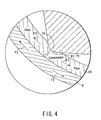
- the portions of the member 10 corresponding to the corner portions X1 and Y1 and inner surfaces X2 and Y2 receive a compression load, as is shown in FIGS. 3B and 4.
- part of the material of the deformation assisting member 10 plastically flows to escape from the corner portions X1 and Y1.
- the arrows F1 in FIG. 4 indicate the flow directions of the material of the deformation assisting member 10.
- the outer peripheral surface of the steel pipe 6 is in pressure contact with the inner peripheral surface of the deformation assisting member 10 by the inner pressure applied to the steel pipe 6. Accordingly, the peripheral wall of the steel pipe 6 that overlaps the portion of the deformation assisting member 10, at which plastic flow occurs, is dragged in the flow directions of the material of the deformation assisting member 10 by friction therebetween.
- the peripheral wall of the steel pipe 6 is extended in the directions indicated by the arrows F2 in FIG. 4, along the flow directions F1 of the deformation assisting member 10. This being so, the deformation of the steel pipe 6 is not interrupted at the portions kept in contact with the die assembly 5, i.e., the steel pipe is smoothly expanded.
- the deformation assisting member 10 is provided along the corner portions X1 and Y1 and inner surfaces X2 and Y2, with which the outer periphery of the steel pipe 6 is earliest brought into contact during hydroforming, and also along the molding areas L1 and L2 where the deformation is locally advanced. Therefore, when the deformation assisting member 10 plastically flows, expansion is advanced in the molding areas L1 and L2 to the same degree as the other portions, as is shown in FIG. 3C. In other words, hydroforming is executed without a local reduction in wall thickness.
- the deformation assisting member 10 is finally pressed against the molding surfaces 1 and 3 of the die assembly 5 and is formed into a desired product shape together with the steel pipe 6.
- the reinforcing member 7 with the deformation assisting member 10 press-fitted on the pipe is obtained as shown in FIG. 2B.
- the portions of the deformation assisting member 10 that correspond to the molding areas L1 and L2 are thick as a result of plastic flow. Accordingly, the portions of the reinforcing member 7 that correspond to the molding areas L1 and L2 are thicker than the other portions.
- the hydroform product has a complicated sectional shape
- an original tube member e.g. a steel pipe
- the wall thickness of the original tube member is locally reduced as a result of local contact between the original tube member and die assembly 5 that occurs during forming.
- the wall thickness t3 (indicated in FIG. 3C) of the steel pipe 6 is substantially uniform over the entire circumference by virtue of hydroforming using the properties of the composite member that consists of the steel pipe 6 and deformation assisting member 10. This being so, disadvantages such as cracks, breakages, etc. of the steel pipe 6 can be avoided.
- the deformation assisting member 10 formed of a tubular member is fitted on the outer peripheral surface of the steel pipe 6. Therefore, when the steel pipe 6 is expanded, the outer peripheral surface of the steel pipe 6 can be easily and tightly attached to the inner surface of the deformation assisting member 10. As a result, the deformation (expansion) of the steel pipe 6 due to the plastic flow of the deformation assisting member 10 can be smoothly advanced.
- the wall thickness t3 of the steel pipe 6 can be made uniform, even a hydroform product, such as a reinforcing member 7 of a complicated sectional shape, can be made to have a high rigidity by thinning the wall thickness while utilizing the features of the hydroform process.
- portions of the steel pipe may be individually covered with a plurality of deformation assisting members, instead of covering the greater part of the steel pipe with a single deformation assisting member as in the embodiment.
- the deformation assisting member formed of a tubular member is kept in tight contact with the outer peripheral surface of the steel pipe, thereby extending the peripheral wall of the steel pipe in accordance with the plastic flow of the deformation assisting member.
- the assisting member is not limited to the tubular deformation assisting member.
- an assisting member in the form of a sheet may be fixed to the outer peripheral surface of the steel pipe by fixing means such as welding or adhesion.
- the assisting sheet member may be provided on the area ranging from the predetermined portions of the outer peripheral surface of the steel pipe, which are earliest brought into contact with the inner surface of the die assembly during expansion, to the molding areas in which local extension occurs.
- the assisting member of the invention may be provided not only on the area ranging from the aforementioned predetermined portions of the original tube member to the molding areas, but also on the other outer peripheral surfaces.
- the embodiment describes a reinforcing member for use in the body of a vehicle, the invention is not limited to the forming of reinforcing members, but is also applicable to the forming of other vehicle members or members used for other purposes.
- the original tube member is not limited to steel pipes but may be other pipes.
- the hydroform product of the invention can be used to form various components, in addition to a reinforcing member for reinforcing the body of a vehicle. Further, it can be used for various structures other than vehicles.
Landscapes
- Engineering & Computer Science (AREA)
- Mechanical Engineering (AREA)
- Physics & Mathematics (AREA)
- Fluid Mechanics (AREA)
- Shaping Metal By Deep-Drawing, Or The Like (AREA)
Abstract
Description
Claims (8)
- A hydroform process of advancing expansion of an original tube member (6), with a predetermined portion (1b) kept in contact with an outer peripheral surface of the original tube member (6), by pressuring the original tube member (6) from inside, using a die assembly (5) having molding surfaces (1, 3) and the predetermined portion (1b), the predetermined portion (1b) being included in the molding surfaces (1, 3) and earliest brought into contact with the outer peripheral surface of the original tube member (6) during hydroforming, characterized by comprising:attaching an assisting member (10), made of an incompressible material softer than the original tube member (6), at least to an area included in the outer peripheral surface of the original tube member (6) and corresponding to the predetermined portion (1b) of the die assembly (5);setting, into the die assembly (5), the original tube member (6) with the assisting member (10) attached thereto; andpressuring the original tube member (6) from inside, thereby forming the original tube member (6) into a shape corresponding to the molding surfaces (1, 3).
- A hydroform process according to claim 1, characterized in that the assisting member (10) is a tubular member to be fitted on the outer peripheral surface of the original tube member (6), an inner surface of the assisting member (10) being brought into tight contact with the outer peripheral surface of the original tube member (6) as the tube member (6) expands.
- A hydroform process according to claim 1 or 2, characterized in that the original tube member (6) is a steel pipe, and the assisting member (10) is made of a low carbon steel.
- A hydroform process according to claim 1 or 2, characterized in that the original tube member (6) is a steel tube, and the assisting member (10) is made of aluminum.
- A hydroform product obtained by forming an original tube member (6) into a shape corresponding to molding surfaces (1, 3) by pressuring the original tube member (6) from inside, using a die assembly (5) that has the molding surfaces (1, 3) and a predetermined portion (1b) included in the molding surfaces and projects toward an outer peripheral surface of the original tube member (6), characterized in that:an assisting member (10), made of an incompressible material softer than the original tube member (6), is in contact at least with an area included in the outer peripheral surface of the original tube member (6) and corresponding to the predetermined portion (1b) of the die assembly (5).
- A hydroform product according to claim 5, characterized in that the assisting member (10) is a tubular member to be fitted on the outer peripheral surface of the original tube member (6).
- A hydroform product according to claim 5 or 6, characterized in that the original tube member (6) is a steel tube, and the assisting member (10) is made of a low carbon steel.
- A hydroform product according to claim 5 or 6, characterized in that the original tube member (6) is a steel tube, and the assisting member (10) is made of aluminum.
Applications Claiming Priority (3)
| Application Number | Priority Date | Filing Date | Title |
|---|---|---|---|
| JP2001152775 | 2001-05-22 | ||
| JP2001152775 | 2001-05-22 | ||
| PCT/JP2002/004741 WO2002094472A1 (en) | 2001-05-22 | 2002-05-16 | Hydroform process, and hydroform product formed by the process |
Publications (2)
| Publication Number | Publication Date |
|---|---|
| EP1389497A1 true EP1389497A1 (en) | 2004-02-18 |
| EP1389497A4 EP1389497A4 (en) | 2009-04-29 |
Family
ID=18997396
Family Applications (1)
| Application Number | Title | Priority Date | Filing Date |
|---|---|---|---|
| EP02771708A Withdrawn EP1389497A4 (en) | 2001-05-22 | 2002-05-16 | HYDROFORMING PROCESS AND HYDROFORM PRODUCT ACCORDING TO SAID METHOD |
Country Status (7)
| Country | Link |
|---|---|
| US (1) | US7051768B2 (en) |
| EP (1) | EP1389497A4 (en) |
| JP (1) | JP4207570B2 (en) |
| KR (1) | KR100472537B1 (en) |
| CN (2) | CN1222378C (en) |
| TW (1) | TW526102B (en) |
| WO (1) | WO2002094472A1 (en) |
Cited By (1)
| Publication number | Priority date | Publication date | Assignee | Title |
|---|---|---|---|---|
| EP2095890A3 (en) * | 2008-03-01 | 2012-01-18 | Audi AG | Method for shaping a hollow profile component with high internal pressure |
Families Citing this family (28)
| Publication number | Priority date | Publication date | Assignee | Title |
|---|---|---|---|---|
| DE10323738B3 (en) * | 2003-05-24 | 2004-11-18 | Daimlerchrysler Ag | Manufacturing closed hollow profile involves cutting semi-finished product ends to form angled ends before squeezing; contour, angle are selected so ends form essentially flat shape after squeezing |
| CA2601585A1 (en) | 2005-03-17 | 2006-09-28 | Industrial Origami, Llc | Precision-folded, high strength, fatigue-resistant structures and sheet therefor |
| JP4664103B2 (en) * | 2005-03-23 | 2011-04-06 | 昭和電工株式会社 | Steering support beam and manufacturing method thereof |
| US7546754B2 (en) * | 2005-04-14 | 2009-06-16 | Gm Global Technology Operations, Inc. | Method of fabricating tubular structure from hybrid material |
| CA2551262A1 (en) * | 2005-07-29 | 2007-01-29 | Salflex Polymers Ltd. | Method for making plastic metal composite parts |
| CN100475376C (en) * | 2006-03-31 | 2009-04-08 | 坤威实业有限公司 | Pipe fitting forming method |
| TW200833434A (en) * | 2006-09-04 | 2008-08-16 | Ind Origami Inc | Apparatus for forming large-radii curved surfaces and small-radii creases in sheet material |
| JP2010508150A (en) | 2006-10-26 | 2010-03-18 | インダストリアル オリガミ インコーポレイテッド | Method for forming planar sheet material into a three-dimensional structure |
| CN101652597A (en) | 2007-02-09 | 2010-02-17 | 奥里加米工业股份有限公司 | Load-carrying 3D structures |
| CN102256861A (en) * | 2008-12-17 | 2011-11-23 | 沃尔沃拉斯特瓦格纳公司 | Cast steering knuckle for a vehicle and vehicle comprising a cast steering knuckle |
| US8171769B2 (en) * | 2009-01-27 | 2012-05-08 | Ford Global Technologies | Method of forming a flanged tubular member in hydroforming |
| US9302307B2 (en) * | 2009-02-16 | 2016-04-05 | Vari-Form, Inc. | Method of forming hollow body with flange |
| KR200451899Y1 (en) * | 2009-08-12 | 2011-01-18 | 주현철 | Installation structure of traffic signal control box |
| DE102009041919A1 (en) * | 2009-09-17 | 2011-03-31 | Tyco Electronics Amp Gmbh | Electrical contact element for high current connectors and manufacturing processes |
| KR100963423B1 (en) * | 2009-11-12 | 2010-06-15 | 현대하이스코 주식회사 | Method of manufacturing double-layer water pipe using hydro forming |
| JP2011133141A (en) * | 2009-12-22 | 2011-07-07 | Kazuo Taka | Heating pipe and cooking machine |
| US8505349B2 (en) * | 2011-05-11 | 2013-08-13 | Ford Global Technologies, Llc | Method and apparatus for hydro-forming an elongated tubular member |
| CN102489582A (en) * | 2011-11-18 | 2012-06-13 | 吉林大学 | Flexible forming method of variable cross-section special-shaped piece with closed cavities |
| CN104220231A (en) * | 2012-03-14 | 2014-12-17 | 可持续太阳能公司 | A method of fabricating a component of a solar energy system |
| US8936164B2 (en) * | 2012-07-06 | 2015-01-20 | Industrial Origami, Inc. | Solar panel rack |
| US8910500B2 (en) | 2012-09-10 | 2014-12-16 | National Research Council Of Canada | Low friction end feeding in tube hydroforming |
| EP2746155B1 (en) * | 2012-12-21 | 2015-07-08 | Bell Helicopter Textron Inc. | Helicopter skid landing gear |
| CN103785755B (en) * | 2014-02-28 | 2016-01-20 | 上海理工大学 | The hydraulic pressure mfg. moulding die of the double-deck pipe fitting of binary channels, manufacturing system and manufacture method |
| CN103920787B (en) * | 2014-03-27 | 2016-01-27 | 宝山钢铁股份有限公司 | A kind of hydraulic forming method of pipe fitting torsion beam |
| GB2533644B (en) * | 2014-12-24 | 2017-12-06 | Acergy France SAS | Improving the bending behaviour of mechanically-lined rigid pipe |
| DE112016003254T5 (en) * | 2015-07-20 | 2018-04-26 | Magna International Inc. | Body and chassis components with ultra-high strength |
| US9822908B2 (en) * | 2015-12-10 | 2017-11-21 | Ford Global Technologies, Llc | Hydroform tube and method of forming |
| CN105834273B (en) * | 2016-03-30 | 2017-12-05 | 成霖企业股份有限公司 | Pipe fitting hydraulic forming method |
Family Cites Families (21)
| Publication number | Priority date | Publication date | Assignee | Title |
|---|---|---|---|---|
| DE3135966C2 (en) * | 1981-09-11 | 1986-06-05 | Hoesch Ag, 4600 Dortmund | Process for the manufacture of multilayer screw sutures |
| US4759111A (en) * | 1987-08-27 | 1988-07-26 | Ti Automotive Division Of Ti Canada Inc. | Method of forming reinforced box-selection frame members |
| JPH0280130A (en) | 1988-09-13 | 1990-03-20 | Mazda Motor Corp | Hydroforming equipment |
| US5170557A (en) * | 1991-05-01 | 1992-12-15 | Benteler Industries, Inc. | Method of forming a double wall, air gap exhaust duct component |
| DE69403722T2 (en) * | 1993-04-19 | 1997-09-25 | Gen Motors Corp | Process for forming a tubular element |
| US5363544A (en) * | 1993-05-20 | 1994-11-15 | Benteler Industries, Inc. | Multi-stage dual wall hydroforming |
| US5582052A (en) * | 1993-05-20 | 1996-12-10 | Benteler Industries, Inc. | Controlled time-overlapped hydroforming |
| US5495873A (en) * | 1993-10-13 | 1996-03-05 | Benteler Industries, Inc. | Patterned air gap engine exhaust conduit |
| US5673470A (en) * | 1995-08-31 | 1997-10-07 | Benteler Automotive Corporation | Extended jacket end, double expansion hydroforming |
| CN1073896C (en) * | 1996-08-27 | 2001-10-31 | 章新生 | Method for production of double metal pipe and internal wall wearing-resistance metal pipe |
| JP3672408B2 (en) * | 1997-03-14 | 2005-07-20 | 本田技研工業株式会社 | Manufacturing method of frame-like structure |
| US6209319B1 (en) * | 1998-09-28 | 2001-04-03 | Honda Giken Kogyo Kabushiki Kaisha | Pipe assembly having inner and outer pipes |
| US6484384B1 (en) * | 1998-12-31 | 2002-11-26 | Spicer Driveshaft, Inc. | Method of manufacturing an axially collapsible driveshaft assembly |
| US6254488B1 (en) * | 1999-07-13 | 2001-07-03 | Daimlerchrysler Corporation | Hydroformed drive shaft and method of making the same |
| JP2001062522A (en) * | 1999-08-26 | 2001-03-13 | Nippon Steel Corp | Double tube hydroform processing method |
| US6497030B1 (en) * | 1999-08-31 | 2002-12-24 | Dana Corporation | Method of manufacturing a lead screw and sleeve mechanism using a hydroforming process |
| JP2001219226A (en) * | 2000-02-04 | 2001-08-14 | Kawasaki Steel Corp | High-strength steel pipe for hydroforming |
| JP4631130B2 (en) * | 2000-05-25 | 2011-02-16 | 住友金属工業株式会社 | Modified tubular product and manufacturing method thereof |
| JP2001353519A (en) * | 2000-06-14 | 2001-12-25 | Suncall Corp | Dual structured clad tube and its manufacturing method |
| JP3738828B2 (en) * | 2001-01-19 | 2006-01-25 | トヨタ自動車株式会社 | Double tube structure hollow member, method for producing the same, and fluid treatment system using double tube structure hollow member |
| US6742576B2 (en) * | 2001-09-27 | 2004-06-01 | E. I. Du Pont De Nemours And Company | Heat exchanger barrier ribbon with polymeric tubes |
-
2002
- 2002-05-16 CN CNB028017692A patent/CN1222378C/en not_active Expired - Fee Related
- 2002-05-16 EP EP02771708A patent/EP1389497A4/en not_active Withdrawn
- 2002-05-16 WO PCT/JP2002/004741 patent/WO2002094472A1/en not_active Ceased
- 2002-05-16 CN CNB2005100916150A patent/CN100368109C/en not_active Expired - Fee Related
- 2002-05-16 JP JP2002591177A patent/JP4207570B2/en not_active Expired - Fee Related
- 2002-05-20 TW TW091110522A patent/TW526102B/en not_active IP Right Cessation
- 2002-05-20 KR KR10-2002-0027870A patent/KR100472537B1/en not_active Expired - Fee Related
-
2003
- 2003-01-08 US US10/337,994 patent/US7051768B2/en not_active Expired - Fee Related
Cited By (1)
| Publication number | Priority date | Publication date | Assignee | Title |
|---|---|---|---|---|
| EP2095890A3 (en) * | 2008-03-01 | 2012-01-18 | Audi AG | Method for shaping a hollow profile component with high internal pressure |
Also Published As
| Publication number | Publication date |
|---|---|
| EP1389497A4 (en) | 2009-04-29 |
| KR20020089183A (en) | 2002-11-29 |
| US7051768B2 (en) | 2006-05-30 |
| WO2002094472A1 (en) | 2002-11-28 |
| KR100472537B1 (en) | 2005-03-08 |
| CN1222378C (en) | 2005-10-12 |
| JPWO2002094472A1 (en) | 2004-09-02 |
| JP4207570B2 (en) | 2009-01-14 |
| CN1827253A (en) | 2006-09-06 |
| TW526102B (en) | 2003-04-01 |
| US20030102045A1 (en) | 2003-06-05 |
| CN1463209A (en) | 2003-12-24 |
| CN100368109C (en) | 2008-02-13 |
Similar Documents
| Publication | Publication Date | Title |
|---|---|---|
| US7051768B2 (en) | Hydroform process and hydroform product | |
| US20070234771A1 (en) | Method of Hydraulic bulging and shaft pressing profile element pipe to make hydraulically bulged product | |
| US7827839B2 (en) | Profile element pipe for hydraulic bulging, hydraulic bulging device using the element pipe, hydraulic bulging method using the element pipe, and hydraulically bulged product | |
| US5775740A (en) | Structure and process for jointing small-diameter thin metal tube and pressure rubber hose | |
| CN101657278B (en) | Method of hydroforming work | |
| US6260401B1 (en) | Method of molding high expansion pipe and the high expansion pipe | |
| CN110586721B (en) | Method for manufacturing curved member | |
| CN101657279B (en) | Hydroformed article | |
| US6763693B1 (en) | Method for shaping an initial profile or a similar workpiece using an internal high pressure and profile therefor | |
| JP2001340922A (en) | Manufacturing method of T-joint parts and mold for hydroforming | |
| JP3687838B2 (en) | Fluid pressure molding method, fluid pressure mold and fluid pressure molded member | |
| JP2004344968A (en) | Method for manufacturing burring worked part | |
| JP4060723B2 (en) | Hydraulic bulge processing apparatus and hydraulic bulge processing method | |
| JPH0957380A (en) | Manufacture of cylindrical parts | |
| US7024898B1 (en) | Method for hydroforming a hollow profile | |
| JP4377529B2 (en) | Hydroform processing method of extruded aluminum | |
| JPH11208417A (en) | Steering shaft and method of manufacturing the same | |
| JP4664521B2 (en) | Processing method of wheel disc for automobile | |
| JPH11333527A (en) | Method for manufacturing tubular member for vehicle body structure | |
| US9687901B2 (en) | Method of hydroforming of hollow structural component | |
| JP2002273525A (en) | Hydraulic forming method of laminated plate | |
| JP2003053439A (en) | End sealing device for bulging machine for cylindrical body | |
| JP2005186114A (en) | Caulking die and caulking method for hose fitting | |
| JP2000246359A (en) | Shaft metal fittings and metal pipe processing method using the same | |
| JP2002361324A (en) | Bending method and bent product formed by the method |
Legal Events
| Date | Code | Title | Description |
|---|---|---|---|
| PUAI | Public reference made under article 153(3) epc to a published international application that has entered the european phase |
Free format text: ORIGINAL CODE: 0009012 |
|
| 17P | Request for examination filed |
Effective date: 20030220 |
|
| AK | Designated contracting states |
Kind code of ref document: A1 Designated state(s): DE FR GB NL |
|
| A4 | Supplementary search report drawn up and despatched |
Effective date: 20090326 |
|
| RIC1 | Information provided on ipc code assigned before grant |
Ipc: B21D 26/02 20060101AFI20021204BHEP Ipc: B21D 53/88 20060101ALI20090320BHEP |
|
| 17Q | First examination report despatched |
Effective date: 20090720 |
|
| GRAP | Despatch of communication of intention to grant a patent |
Free format text: ORIGINAL CODE: EPIDOSNIGR1 |
|
| RTI1 | Title (correction) |
Free format text: HYDROFORMING PROCESS |
|
| STAA | Information on the status of an ep patent application or granted ep patent |
Free format text: STATUS: THE APPLICATION HAS BEEN WITHDRAWN |
|
| 18W | Application withdrawn |
Effective date: 20101201 |