EP1388461A2 - Lighting device for a vehicle and method for controlling light distribution of the lighting device - Google Patents
Lighting device for a vehicle and method for controlling light distribution of the lighting device Download PDFInfo
- Publication number
- EP1388461A2 EP1388461A2 EP03017976A EP03017976A EP1388461A2 EP 1388461 A2 EP1388461 A2 EP 1388461A2 EP 03017976 A EP03017976 A EP 03017976A EP 03017976 A EP03017976 A EP 03017976A EP 1388461 A2 EP1388461 A2 EP 1388461A2
- Authority
- EP
- European Patent Office
- Prior art keywords
- light emitting
- light
- lighting device
- vehicle
- devices
- Prior art date
- Legal status (The legal status is an assumption and is not a legal conclusion. Google has not performed a legal analysis and makes no representation as to the accuracy of the status listed.)
- Granted
Links
Images


Classifications
-
- B—PERFORMING OPERATIONS; TRANSPORTING
- B60—VEHICLES IN GENERAL
- B60Q—ARRANGEMENT OF SIGNALLING OR LIGHTING DEVICES, THE MOUNTING OR SUPPORTING THEREOF OR CIRCUITS THEREFOR, FOR VEHICLES IN GENERAL
- B60Q1/00—Arrangement of optical signalling or lighting devices, the mounting or supporting thereof or circuits therefor
- B60Q1/02—Arrangement of optical signalling or lighting devices, the mounting or supporting thereof or circuits therefor the devices being primarily intended to illuminate the way ahead or to illuminate other areas of way or environments
- B60Q1/04—Arrangement of optical signalling or lighting devices, the mounting or supporting thereof or circuits therefor the devices being primarily intended to illuminate the way ahead or to illuminate other areas of way or environments the devices being headlights
- B60Q1/06—Arrangement of optical signalling or lighting devices, the mounting or supporting thereof or circuits therefor the devices being primarily intended to illuminate the way ahead or to illuminate other areas of way or environments the devices being headlights adjustable, e.g. remotely-controlled from inside vehicle
- B60Q1/08—Arrangement of optical signalling or lighting devices, the mounting or supporting thereof or circuits therefor the devices being primarily intended to illuminate the way ahead or to illuminate other areas of way or environments the devices being headlights adjustable, e.g. remotely-controlled from inside vehicle automatically
- B60Q1/085—Arrangement of optical signalling or lighting devices, the mounting or supporting thereof or circuits therefor the devices being primarily intended to illuminate the way ahead or to illuminate other areas of way or environments the devices being headlights adjustable, e.g. remotely-controlled from inside vehicle automatically due to special conditions, e.g. adverse weather, type of road, badly illuminated road signs or potential dangers
-
- F—MECHANICAL ENGINEERING; LIGHTING; HEATING; WEAPONS; BLASTING
- F21—LIGHTING
- F21S—NON-PORTABLE LIGHTING DEVICES; SYSTEMS THEREOF; VEHICLE LIGHTING DEVICES SPECIALLY ADAPTED FOR VEHICLE EXTERIORS
- F21S41/00—Illuminating devices specially adapted for vehicle exteriors, e.g. headlamps
- F21S41/10—Illuminating devices specially adapted for vehicle exteriors, e.g. headlamps characterised by the light source
- F21S41/14—Illuminating devices specially adapted for vehicle exteriors, e.g. headlamps characterised by the light source characterised by the type of light source
- F21S41/141—Light emitting diodes [LED]
- F21S41/143—Light emitting diodes [LED] the main emission direction of the LED being parallel to the optical axis of the illuminating device
-
- F—MECHANICAL ENGINEERING; LIGHTING; HEATING; WEAPONS; BLASTING
- F21—LIGHTING
- F21S—NON-PORTABLE LIGHTING DEVICES; SYSTEMS THEREOF; VEHICLE LIGHTING DEVICES SPECIALLY ADAPTED FOR VEHICLE EXTERIORS
- F21S41/00—Illuminating devices specially adapted for vehicle exteriors, e.g. headlamps
- F21S41/10—Illuminating devices specially adapted for vehicle exteriors, e.g. headlamps characterised by the light source
- F21S41/14—Illuminating devices specially adapted for vehicle exteriors, e.g. headlamps characterised by the light source characterised by the type of light source
- F21S41/141—Light emitting diodes [LED]
- F21S41/151—Light emitting diodes [LED] arranged in one or more lines
- F21S41/153—Light emitting diodes [LED] arranged in one or more lines arranged in a matrix
-
- F—MECHANICAL ENGINEERING; LIGHTING; HEATING; WEAPONS; BLASTING
- F21—LIGHTING
- F21S—NON-PORTABLE LIGHTING DEVICES; SYSTEMS THEREOF; VEHICLE LIGHTING DEVICES SPECIALLY ADAPTED FOR VEHICLE EXTERIORS
- F21S41/00—Illuminating devices specially adapted for vehicle exteriors, e.g. headlamps
- F21S41/20—Illuminating devices specially adapted for vehicle exteriors, e.g. headlamps characterised by refractors, transparent cover plates, light guides or filters
- F21S41/24—Light guides
-
- F—MECHANICAL ENGINEERING; LIGHTING; HEATING; WEAPONS; BLASTING
- F21—LIGHTING
- F21S—NON-PORTABLE LIGHTING DEVICES; SYSTEMS THEREOF; VEHICLE LIGHTING DEVICES SPECIALLY ADAPTED FOR VEHICLE EXTERIORS
- F21S41/00—Illuminating devices specially adapted for vehicle exteriors, e.g. headlamps
- F21S41/20—Illuminating devices specially adapted for vehicle exteriors, e.g. headlamps characterised by refractors, transparent cover plates, light guides or filters
- F21S41/25—Projection lenses
- F21S41/27—Thick lenses
-
- F—MECHANICAL ENGINEERING; LIGHTING; HEATING; WEAPONS; BLASTING
- F21—LIGHTING
- F21S—NON-PORTABLE LIGHTING DEVICES; SYSTEMS THEREOF; VEHICLE LIGHTING DEVICES SPECIALLY ADAPTED FOR VEHICLE EXTERIORS
- F21S41/00—Illuminating devices specially adapted for vehicle exteriors, e.g. headlamps
- F21S41/20—Illuminating devices specially adapted for vehicle exteriors, e.g. headlamps characterised by refractors, transparent cover plates, light guides or filters
- F21S41/28—Cover glass
-
- F—MECHANICAL ENGINEERING; LIGHTING; HEATING; WEAPONS; BLASTING
- F21—LIGHTING
- F21S—NON-PORTABLE LIGHTING DEVICES; SYSTEMS THEREOF; VEHICLE LIGHTING DEVICES SPECIALLY ADAPTED FOR VEHICLE EXTERIORS
- F21S41/00—Illuminating devices specially adapted for vehicle exteriors, e.g. headlamps
- F21S41/60—Illuminating devices specially adapted for vehicle exteriors, e.g. headlamps characterised by a variable light distribution
- F21S41/65—Illuminating devices specially adapted for vehicle exteriors, e.g. headlamps characterised by a variable light distribution by acting on light sources
- F21S41/663—Illuminating devices specially adapted for vehicle exteriors, e.g. headlamps characterised by a variable light distribution by acting on light sources by switching light sources
-
- F—MECHANICAL ENGINEERING; LIGHTING; HEATING; WEAPONS; BLASTING
- F21—LIGHTING
- F21S—NON-PORTABLE LIGHTING DEVICES; SYSTEMS THEREOF; VEHICLE LIGHTING DEVICES SPECIALLY ADAPTED FOR VEHICLE EXTERIORS
- F21S45/00—Arrangements within vehicle lighting devices specially adapted for vehicle exteriors, for purposes other than emission or distribution of light
- F21S45/60—Heating of lighting devices, e.g. for demisting
-
- B—PERFORMING OPERATIONS; TRANSPORTING
- B60—VEHICLES IN GENERAL
- B60Q—ARRANGEMENT OF SIGNALLING OR LIGHTING DEVICES, THE MOUNTING OR SUPPORTING THEREOF OR CIRCUITS THEREFOR, FOR VEHICLES IN GENERAL
- B60Q2300/00—Indexing codes for automatically adjustable headlamps or automatically dimmable headlamps
- B60Q2300/05—Special features for controlling or switching of the light beam
- B60Q2300/054—Variable non-standard intensity, i.e. emission of various beam intensities different from standard intensities, e.g. continuous or stepped transitions of intensity
-
- B—PERFORMING OPERATIONS; TRANSPORTING
- B60—VEHICLES IN GENERAL
- B60Q—ARRANGEMENT OF SIGNALLING OR LIGHTING DEVICES, THE MOUNTING OR SUPPORTING THEREOF OR CIRCUITS THEREFOR, FOR VEHICLES IN GENERAL
- B60Q2300/00—Indexing codes for automatically adjustable headlamps or automatically dimmable headlamps
- B60Q2300/10—Indexing codes relating to particular vehicle conditions
- B60Q2300/11—Linear movements of the vehicle
- B60Q2300/112—Vehicle speed
-
- B—PERFORMING OPERATIONS; TRANSPORTING
- B60—VEHICLES IN GENERAL
- B60Q—ARRANGEMENT OF SIGNALLING OR LIGHTING DEVICES, THE MOUNTING OR SUPPORTING THEREOF OR CIRCUITS THEREFOR, FOR VEHICLES IN GENERAL
- B60Q2300/00—Indexing codes for automatically adjustable headlamps or automatically dimmable headlamps
- B60Q2300/10—Indexing codes relating to particular vehicle conditions
- B60Q2300/11—Linear movements of the vehicle
- B60Q2300/114—Vehicle acceleration or deceleration
-
- B—PERFORMING OPERATIONS; TRANSPORTING
- B60—VEHICLES IN GENERAL
- B60Q—ARRANGEMENT OF SIGNALLING OR LIGHTING DEVICES, THE MOUNTING OR SUPPORTING THEREOF OR CIRCUITS THEREFOR, FOR VEHICLES IN GENERAL
- B60Q2300/00—Indexing codes for automatically adjustable headlamps or automatically dimmable headlamps
- B60Q2300/10—Indexing codes relating to particular vehicle conditions
- B60Q2300/12—Steering parameters
- B60Q2300/122—Steering angle
-
- B—PERFORMING OPERATIONS; TRANSPORTING
- B60—VEHICLES IN GENERAL
- B60Q—ARRANGEMENT OF SIGNALLING OR LIGHTING DEVICES, THE MOUNTING OR SUPPORTING THEREOF OR CIRCUITS THEREFOR, FOR VEHICLES IN GENERAL
- B60Q2300/00—Indexing codes for automatically adjustable headlamps or automatically dimmable headlamps
- B60Q2300/10—Indexing codes relating to particular vehicle conditions
- B60Q2300/13—Attitude of the vehicle body
- B60Q2300/132—Pitch
-
- B—PERFORMING OPERATIONS; TRANSPORTING
- B60—VEHICLES IN GENERAL
- B60Q—ARRANGEMENT OF SIGNALLING OR LIGHTING DEVICES, THE MOUNTING OR SUPPORTING THEREOF OR CIRCUITS THEREFOR, FOR VEHICLES IN GENERAL
- B60Q2300/00—Indexing codes for automatically adjustable headlamps or automatically dimmable headlamps
- B60Q2300/20—Indexing codes relating to the driver or the passengers
- B60Q2300/21—Manual control
-
- B—PERFORMING OPERATIONS; TRANSPORTING
- B60—VEHICLES IN GENERAL
- B60Q—ARRANGEMENT OF SIGNALLING OR LIGHTING DEVICES, THE MOUNTING OR SUPPORTING THEREOF OR CIRCUITS THEREFOR, FOR VEHICLES IN GENERAL
- B60Q2300/00—Indexing codes for automatically adjustable headlamps or automatically dimmable headlamps
- B60Q2300/30—Indexing codes relating to the vehicle environment
- B60Q2300/31—Atmospheric conditions
- B60Q2300/312—Adverse weather
-
- F—MECHANICAL ENGINEERING; LIGHTING; HEATING; WEAPONS; BLASTING
- F21—LIGHTING
- F21W—INDEXING SCHEME ASSOCIATED WITH SUBCLASSES F21K, F21L, F21S and F21V, RELATING TO USES OR APPLICATIONS OF LIGHTING DEVICES OR SYSTEMS
- F21W2107/00—Use or application of lighting devices on or in particular types of vehicles
-
- F—MECHANICAL ENGINEERING; LIGHTING; HEATING; WEAPONS; BLASTING
- F21—LIGHTING
- F21Y—INDEXING SCHEME ASSOCIATED WITH SUBCLASSES F21K, F21L, F21S and F21V, RELATING TO THE FORM OR THE KIND OF THE LIGHT SOURCES OR OF THE COLOUR OF THE LIGHT EMITTED
- F21Y2115/00—Light-generating elements of semiconductor light sources
- F21Y2115/10—Light-emitting diodes [LED]
Definitions
- the present invention relates to a lighting device for a vehicle and a method for controlling a light distribution of the lighting device.
- a lighting device for a vehicle is used in different applications including headlamps, fog lamps, tale lamps, break lamps, and turn signal lamps.
- the vehicle includes passenger vehicles, motorcycles, bicycles, construction vehicles, and aircrafts.
- the lighting device has a light source, such as an incandescent lamp and a halogen lamp, a reflector, and a lens to obtain desired characteristics of the light distribution.
- the incandescent lamp and the halogen lamp are not efficient in converting electricity to light. Thus, a large amount of electricity is required to produce light of desirable intensity. This may lower the fuel economy in an engine-driven vehicle and the mileage per charge in an electric vehicle.
- lifetimes of the incandescent lamp and the halogen lamp are normally shorter than a lifetime of a vehicle.
- the number of periodical replacement of the lamps increases according to the period that the vehicle is used, that is, the number of times that the lamp is used.
- HID high intensity discharge
- periodical replacement of the lamp is required. If daytime-lighting becomes mandatory for safety, the lifetime of the lamps may become a critical issue.
- LEDs light emitting diodes
- JP-A-10-228803 JP-A-2001-291901, JP-U-3080310, JP-A-10-109587, JP-A-2001-126510, JP-U-6-53294, JP-A-2000-331508, JP-A-7-288011, and JP-A-2000-58925.
- the LEDs is highly efficient in converting electricity to light and has long lifetimes.
- the LEDs have narrow lighting areas and small angles. Thus, lighting devices constructed of LEDs, a reflector, and a lens cannot provide desirable light distribution.
- JP-A-2001-291901 it is suggested that a plurality of LEDs are mounted in a lens and the lens is shaped so that desirable light distribution is produced.
- JP-A-10-228803 it is suggested that focal distances of convex lenses of LEDs are adjusted to the same length to produce desirable light distribution.
- the suggested lighting devices do not provide much flexibility in altering light distribution.
- the present invention therefore has an objective to provide a lighting device that provides flexibility in altering light distribution.
- the present invention has another objective to provide a method for controlling the light distribution of the lighting device.
- a lighting device of the present invention includes multiple light emitting devices, each of which is constructed of a light emitting diode (LED) as a light source and a light guide lens.
- the light emitting devices are configured to have different optical characteristics.
- An application of the light emitting devices having different optical characteristics has increased flexibility in altering light distribution.
- the LED is highly efficient in converting electricity to light and has a long lifetime with respect to the other types of lighting members, such as an incandescent lamp and a halogen lamp.
- the lifetime of the lighting device constructed of the LEDs is greatly improved.
- the lighting devices are very small in size and thin in comparison with incandescent lamps and halogen lamps. Therefore, the lighting device using the lighting members can be decreased in size and weight. This results in a decrease in weight of a vehicle, and provides more space in an engine compartment. As a result, the flexibility in designing a vehicle improves.
- the light emitting device includes the first light emitting device and the second lighting device.
- the first light emitting device is constructed of the first LED and the first light guide lens.
- the second light emitting device is constructed of the second LED and the second light guide lens.
- the first and the second LEDs are used as light sources.
- the first light guide lens confines light emitted from the first LED to an annular pencil.
- the second light guide lens spreads light emitted from the second LED.
- the first light emitting device increases the intensity of the light in a specific area and the second light emitting device increases a light distribution area.
- a sensitivity of adjustment in the light distribution area and its intensity are improved when a combination of the fist and the second light emitting devices is properly made. In other words, the flexibility in altering light distribution is improved.
- the lighting device does not require a reflector and a driving mechanism such as a motor. Therefore, the construction of the device is simple, the weight of the device is light, and the device is reliable.
- the first and the second light emitting devices are arranged in rows. Driving conditions are determined for the light distribution control of the lighting device. The first and the second light emitting devices are turned on or off based on the driving conditions. The intensity of the first and the second light emitting devices may be adjusted in the light distribution control in addition to turning on or off the devices.
- Headlights for a vehicle are required to have low-beam (dimmer-beam) light distribution areas shown in FIGS. 1A and 1B under the left-hand driving regulations. Higher intensity is required in the white area shown in FIG. 1A compared with the rest of area.
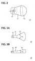
- Each headlight includes convex light emitting devices 10 (first light emitting devices) shown in FIG. 2 and fan-shaped light emitting device 20 (second light emitting devices) shown in FIG.3.
- Each convex device 10 is constructed of a white light emitting diode (LED) 11, a guiding member 12, and a convex light guide lens 13.
- the white LED 11 is provided as a first LED for lighting a narrow area.
- the convex light guide lens 13 having a paraboloidal surface is provided as a first light guide lens for passing light from the white LED 11 to outside in the form of a parallel pencil of light.
- the guiding member 12 is arranged between the white LED 11 and the light guide lens 13. It guides the light emitted from the white LED 11 to the light guide lens 13 so that the light beam does not leak to the outside.
- the guiding member 12 and the light guide lens 13 are integrally formed from acrylic resin, in which the white LED 11 is mounted.
- Each fan-shaped light emitting device 20 is constructed of a white LED 21 (second LED), a guiding member 22, and a fan-shaped light guide lens 23 (second light guide lens).
- the fan-shaped device 20 is provided for lighting a wide area.
- the fan-shaped light guide lens 23 widens a distribution area of the light emitted from the white LED 21.
- the guiding member 22 is arranged between the white LED 21 and the fan-shaped light guide lens 23. It guides the light emitted from the white LED 21 to the light guide lens 23 so that the light beam does not leak to outside.
- the guiding member 12 and the light guide lens 23 are integrally formed from acrylic resin, in which the white LED 21 is mounted.
- Horizontal cross-sectional apex angle ⁇ 1 and vertical cross-sectional apex angle ⁇ 2 of the fan-shaped lens 23 are different from each other.
- the light distribution area is adjusted by setting the apex angle ⁇ 1 and ⁇ 2 at appropriate angles.
- the light distribution areas can be increased by forming the fan-shaped lens in a shape that fans out in both horizontal and vertical directions.
- a single LED is used for each white LED 11, 21.
- a combination of three LEDs from each of which three primary colors are emitted can be used. In that case, yellowish color of the light can be produced for dense fog or bad weather conditions.
- the headlight can include a function of a turn signal indicator performed by flashing LEDs on the side in yellow according to an operation of the turn signal indicator.
- the light emitting devices 10, 20 are configured to have different optical characteristics.
- An application of the light emitting devices having different optical characteristics has increased flexibility in altering light distribution.
- a right headlight RH has the convex devices 10 and the fan-shaped devices 20 arranged in rows.
- the convex devices 10 and the fan-shaped devices 20 are indicated with white circles and shaded circles on which arrows drawn across, respectively.
- Each arrow indicates an orientation of the fan-shaped lens 23 shown in FIG. 4B, that is an orientation of the apex angle ⁇ 1.
- a front view of an outer frame of the right headlight RH is indicated with a trapezoid.
- the straight line on the left side of FIG. 4A and the sloped line are a right edge and a center edge of the right headlight RH, respectively.
- the light distribution control of the headlight RH is performed by a headlight ECU (light distribution control means) 40.
- the headlight ECU 40 is located outside the headlight RH. However, it can be installed in the headlight RH.
- the convex device 10 and the fan-shaped device 20 are independently wired. Therefore, the headlight ECU 40 can independently control on-off switching and the intensity of each device 10, 20.
- the on-off switching and the intensity are controlled by adjusting the amount of current supply to the LEDs 11, 21 in the convex device 10 and the fan-shaped device 20.
- the current supply is controlled by a current control circuit 41 in the headlight ECU 40.
- the headlight ECU 40 receives signals indicative of a variety of information corresponding to driving conditions from different sensors.
- the headlight ECU 40 controls the on-off switching and the intensity of the convex device 10 and the fan-shaped device 20 based on the signals. As a result, proper light distribution is provided according to the driving conditions.
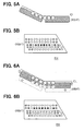
- Light distribution areas of the headlights are provided on a vertical wall located a certain distance away from the headlight at low-beam lighting as shown in FIG. 5A.
- the on-off conditions of the convex devices 10 and the fan-shaped devices 20 are shown in FIG. 5B.
- the devices 10, 20 that are turned on are indicated with center dots.
- the devices 10, 20 in a center row are tuned on except for the ones on the right and the left sides.
- the light distribution areas are provided under a cutline CL. Furthermore, the intensity around the center portion of the light distribution areas is higher than the outer portions.
- the light distribution control is also performed base on a variation in the height or the pitching motion of the vehicle.
- One example of the control is shown in FIG. 6.
- a beam axis of the headlight is adjusted upward as shown in FIGS. 6A and 6B.
- the light emitting devices 10, 20 previously turned on shown in FIG. 5B are turned off and the devices 10, 20 in the row one above are turned on. Therefore, the light distribution of the headlight is properly provided even when the nose of the vehicle slightly has gone down.
- the beam axis of the headlight is adjusted downward so that the light distribution of the headlight is properly provided.
- Which row of the emitting devices 10, 20 are turned on is determined based on the pitching motion of the vehicle. In other words, the emitting devices 10, 20 to light may be shifted more than one row from the previously turned on devices 10, 20. Alternatively, more than one row of the emitting devices 10, 20 may be turned on in addition to the devices 10, 20 that are previously turned on when the pitching motion occurs.
- the beam axis adjustment is performed by the headlight ECU 40 based on information about the height of the vehicle and a pitching angle provided by a leveling sensor and a pitching angle sensor, respectively. More specifically, a correction angle for adjusting the beam axis is determined based on the information, and then which row of the emitting devices 10, 20 are turned on or off is determined. The beam axis may be further adjusted based on a vehicle speed detected by a speed sensor.
- the beam axis is also adjusted in a horizontal direction according to changes in the traveling direction of the vehicle during making a turn or a curve.
- the beam axis is adjusted as shown in FIGS. 7A and 7B when the vehicle goes around a curve to the right.
- the beam axis is shifted to the right. More specifically, the devices 10, 20 located around the center of the headlight RH are turned off, and a larger number of the devices 10, 20 located in the right area are turned on as shown in FIG. 7B. As a result, an area around the end of the curve is properly lit, which improves the visibility of a driver.
- the beam axis adjustment is performed in the same manner as above.
- the amount of beam adjusting is determined based on the steering angle of the vehicle.
- the currently turned-on devices 10, 20 are turned off and appropriate devices are turned on.
- a larger number of the devices 10, 20 are turned on as required in addition to the currently turned-on devices 10, 20 to widen a right or a left lighting area.
- the intensity control may be performed for improving the lighting the area around the end of the curve.
- the beam axis adjustment is performed by the headlight ECU 40 based on information about the steering angle of the vehicle and a posture of the driver.
- the information is obtained from the steering angle sensor provided at a steering wheel, from an acceleration sensor, and from a breaking deceleration sensor installed in the vehicle. More specifically, a correction angle or the intensity for the adjustment is determined based on the information. Then, which emitting devices 10, 20 are turned on or off, or the intensity is determined, in other words, emission control of the light emitting devices 10, 20 is performed.
- the on-off control or the intensity control is performed based on the determination.
- the beam axis and the intensity may be further adjusted based on the driving condition of the vehicle detected by the speed sensor.
- the intensity control is performed, the intensity is increased in specific devices or gradually increased from the center to the edge.
- the light distribution control under bad weather conditions for example in the fog, is shown in FIGS. 8A and 8B.
- the vehicle travels at a reduced speed.
- the devices 10, 20 in the row lower than that shown in FIG. 5B are turned on, the lighting area on the vertical wall ahead of the head light is shifted downward as shown in FIG. 8A.
- the light distribution control is performed by the headlight ECU 40 based on an instruction from the driver in addition to information obtained from outside air temperature and moisture sensors.
- the visibility can be further improved by controlling the intensity and the coloration of the devices 10, 20.
- the coloration control can be implemented when red-green-blue (RGB) LEDs are used instead of the white LEDs 11, 21. Under the normal condition, the LEDs of all three colors are lit to produce white. Under the bad weather condition, the red LEDs and the green LEDs are lit to produce yellowish white. As a result, the fog lamp function can be performed by the headlight.
- RGB red-green-blue
- the light distribution control is performed as shown in FIGS. 9A and 9B.
- the convex devices 10 in the center area for lighting a hot zone are turned off and the fan-shaped devices 20 in the outer areas are turned on.
- the light distribution areas of the headlights have the even intensity.
- the intensity of the convex devices 10 may be reduced instead of being tuned off.
- the light distribution control for high beams (main beams) of the headlight is performed as shown in FIGS. 10A and 10B. More convex devices 10 located in the center area are turned on in addition to the lit devices 10 in FIG. 5B. As a result, the beams reach a further distance. It is preferable that the intensity of the devices 10, 20 that are turned on for normal low-beam lighting is increased for increasing the intensity near the cutline CL. This improves the visibility.
- the headlights have a headlight cover (lighting-device cover) 30 shown in FIG. 30 for covering front surfaces of the light emitting devices 10, 20.
- the cover protects the devices 10, 20 from damages due to fly rocks that may hit the headlights while the vehicle is traveling.
- the headlight cover 30 has a heating device, such as a thing hot-wire 31, an Indium Tin Oxide (ITO) film, a transparent heating film.
- the heating device is used for defrosting the headlights for clear lighting when the headlights become frosty in the snowy or the low temperature condition. Therefore, the visibility of the driver improves.
- the headlight cover 30 may be heated by the heated air from an engine compartment. On-off control of the heating device may be performed manually by the driver or automatically by the headlight ECU 40 based on outside conditions detected by the outside air temperature sensor.
- the plate to which the devices 10, 20 are mounted is not limited to a flat plate.
- the plate can be a curved plate shown in FIG. 11B.
- the same type of LEDs can be used for the first LED 11 and the second LED 21.
- the convex light guide lens has a paraboloidal surface so that light emitted from the diode 11 is diffused in parallel rays, which makes the intensity adjustment easy.
- the light distribution area can be adjusted by altering the lens aperture.
- the lenses may be formed in different shapes suitable for each light emitting device as long as the manufacturing cost is maintained.
- the handleability of them increases. It also reduces a loss of light due to the air between the LED 11 and the convex lens 13. They are easily integrated by making the convex lens 13 from an acrylic resin or a polycarbonate resin.
- the red LED is made from AlGaAs, GaAsp, or GaP (Zn-O)
- the green LED is made from GaP (N)
- the blue LED is made from GaN or Sic. Which material to use can be determined based on the color requirements for the lighting device.
- the light distribution area is provided further from the vehicle when the vehicle speed is high. On the other hand, it is preferable that the light distribution area is closer to the vehicle when the vehicle speed is low.
- the information about the steering angle and the traveling direction is useful for adjusting the beam-axis of the headlight in the horizontal direction.
- the information about the vehicle height, the pitching (angle, the vehicle speed, the acceleration speed, and the breaking deceleration speed is useful for adjusting the beam-axis in the vertical direction.
- the information is also useful for adjusting the beam-axis of a stop lamp, a turn signal indicator lamp, a clearance lamp, a tale lamp, and a license plate lamp.
- the information about the traveling direction is especially useful for activating the turn signal indicator.
- the information about the weather conditions is useful for activating the clearance lamp, the tale lamp, and the license plate lamp.
- the weather information may further include daytime and nighttime.
- the headlights have a headlight cover (lighting-device cover) 30 shown in FIG. 12 for covering front surfaces of the light emitting devices 10, 20.
- the cover protects the devices 10, 20 from damages due to fly rocks that may hit the headlights while the vehicle is traveling.
- the headlight cover 30 has a heating device, such as a thing hot-wire 31, an Indium Tin Oxide (ITO) film, a transparent heating film.
- the heating device is used for defrosting the headlights for clear lighting when the headlights become frosty in the snowy or the low temperature condition. Therefore, the visibility of the driver improves.
- On-off control of the heating device may be performed manually by the driver or automatically by the headlight ECU 40 based on outside conditions detected by the outside air temperature sensor.
- a lighting device (RH) for a vehicle includes multiple light emitting devices (10, 20).
- Each light emitting device (10, 20) is constructed of a light emitting diode (11, 21) as a light source and a light guide lens (13, 23) for guiding light emitted from the light emitting diode (11, 21).
- the light emitting devices (10, 20) are formed in convex light emitting devices (10) and fan-shaped light emitting devices (20).
- the convex devices (10) and the fan-shaped devices (20) have different light distribution characteristics. Therefore, light distribution areas and intensity of the lighting device (RH) are more flexibly adjusted than other lighting devices using light emitting diodes as a light source.
Abstract
Description
- The present invention relates to a lighting device for a vehicle and a method for controlling a light distribution of the lighting device.
- A lighting device for a vehicle is used in different applications including headlamps, fog lamps, tale lamps, break lamps, and turn signal lamps. The vehicle includes passenger vehicles, motorcycles, bicycles, construction vehicles, and aircrafts. The lighting device has a light source, such as an incandescent lamp and a halogen lamp, a reflector, and a lens to obtain desired characteristics of the light distribution.
- The incandescent lamp and the halogen lamp are not efficient in converting electricity to light. Thus, a large amount of electricity is required to produce light of desirable intensity. This may lower the fuel economy in an engine-driven vehicle and the mileage per charge in an electric vehicle.
- Furthermore, lifetimes of the incandescent lamp and the halogen lamp are normally shorter than a lifetime of a vehicle. Thus, the number of periodical replacement of the lamps increases according to the period that the vehicle is used, that is, the number of times that the lamp is used. Even when a high intensity discharge (HID) lamp that has a longer lifetime than the halogen lamp is used, periodical replacement of the lamp is required. If daytime-lighting becomes mandatory for safety, the lifetime of the lamps may become a critical issue.
- To solve the above-described problems, lighting devices using light emitting diodes (LEDs) as light sources are suggested in JP-A-10-228803, JP-A-2001-291901, JP-U-3080310, JP-A-10-109587, JP-A-2001-126510, JP-U-6-53294, JP-A-2000-331508, JP-A-7-288011, and JP-A-2000-58925. The LEDs is highly efficient in converting electricity to light and has long lifetimes. On the other hand, the LEDs have narrow lighting areas and small angles. Thus, lighting devices constructed of LEDs, a reflector, and a lens cannot provide desirable light distribution.
- In JP-A-2001-291901, it is suggested that a plurality of LEDs are mounted in a lens and the lens is shaped so that desirable light distribution is produced. In JP-A-10-228803, it is suggested that focal distances of convex lenses of LEDs are adjusted to the same length to produce desirable light distribution. However, the suggested lighting devices do not provide much flexibility in altering light distribution.
- The present invention therefore has an objective to provide a lighting device that provides flexibility in altering light distribution. The present invention has another objective to provide a method for controlling the light distribution of the lighting device.
- A lighting device of the present invention includes multiple light emitting devices, each of which is constructed of a light emitting diode (LED) as a light source and a light guide lens. The light emitting devices are configured to have different optical characteristics. An application of the light emitting devices having different optical characteristics has increased flexibility in altering light distribution.
- The LED is highly efficient in converting electricity to light and has a long lifetime with respect to the other types of lighting members, such as an incandescent lamp and a halogen lamp. Thus, the lifetime of the lighting device constructed of the LEDs is greatly improved. Furthermore, the lighting devices are very small in size and thin in comparison with incandescent lamps and halogen lamps. Therefore, the lighting device using the lighting members can be decreased in size and weight. This results in a decrease in weight of a vehicle, and provides more space in an engine compartment. As a result, the flexibility in designing a vehicle improves.
- The light emitting device includes the first light emitting device and the second lighting device. The first light emitting device is constructed of the first LED and the first light guide lens. The second light emitting device is constructed of the second LED and the second light guide lens. The first and the second LEDs are used as light sources. The first light guide lens confines light emitted from the first LED to an annular pencil. The second light guide lens spreads light emitted from the second LED.
- The first light emitting device increases the intensity of the light in a specific area and the second light emitting device increases a light distribution area. A sensitivity of adjustment in the light distribution area and its intensity are improved when a combination of the fist and the second light emitting devices is properly made. In other words, the flexibility in altering light distribution is improved.
- Furthermore, the lighting device does not require a reflector and a driving mechanism such as a motor. Therefore, the construction of the device is simple, the weight of the device is light, and the device is reliable.
- In the lighting device for a vehicle, the first and the second light emitting devices are arranged in rows. Driving conditions are determined for the light distribution control of the lighting device. The first and the second light emitting devices are turned on or off based on the driving conditions. The intensity of the first and the second light emitting devices may be adjusted in the light distribution control in addition to turning on or off the devices.
- The above and other objectives, features and advantages of the present invention will become more apparent from the following detailed description made with reference to the accompanying drawings. In the drawings:
- FIG. 1A is a graphical view showing light distribution areas of right and left headlights on a vertical wall according to an embodiment of the present invention;
- FIG. 1B is a plan view showing a vehicle and light distribution areas of the headlights;
- FIG. 2 is a perspective view showing a convex light emitting device according to the embodiment;
- FIG. 3A is a horizontal cross-sectional view showing a fan-shaped light emitting device according to the embodiment;
- FIG. 3B is a vertical cross-sectional view showing the fan-shaped light emitting device shown in FIG. 3A;
- FIG. 4A is a plan view showing an arrangement of the convex light emitting devices and the fan-shaped light emitting devices installed in the right headlight according to the embodiment;
- FIG. 4B is a perspective view showing a part of the fan-shaped light emitting device placed in an orientation that the fan-shaped light emitting device is installed in the headlight;
- FIG. 5A is a graphical view showing the light distribution areas of the headlights at normal low-beam lighting;
- FIG. 5B is an explanatory view showing on-off conditions of the convex and the fan-shaped light emitting devices for providing the light distribution areas shown in FIG. 5A;
- FIG. 6A is a graphical view showing the light distribution areas shifted higher with respect to the areas shown in FIG. 5A at low-beam lighting;
- FIG. 6B is an explanatory view showing on-off conditions of the convex and the fan-shaped light emitting devices for providing the light distribution areas shown in FIG. 6A;
- FIG. 7A is a graphical view showing the light distribution areas shifted to right with respect to the areas shown in FIG. 5A at low-beam lighting;
- FIG. 7B is an explanatory view showing on-off conditions of the convex and the fan-shaped light emitting devices for providing the light distribution areas shown in FIG. 7A;
- FIG. 8A is a graphical view showing the light distribution areas shifted lower with respect to the areas shown in FIG. 5A at low-beam lighting;
- FIG. 8B is an explanatory view showing on-off conditions of the convex and the fan-shaped light emitting devices for providing the light distribution areas shown in FIG. 8A;
- FIG. 9A is a graphical view showing the light distribution areas at low-beam lighting in a lighted environment;
- FIG. 9B is an explanatory view showing on-off conditions of the convex and the fan-shaped light emitting devices for providing the light distribution areas shown in FIG. 9A;
- FIG. 10A is a graphical view showing the light distribution areas at high-beam lighting;
- FIG. 10B is an explanatory view showing on-off conditions of the convex and the fan-shaped light emitting devices for providing the light distribution areas shown in FIG. 10A;
- FIG. 11A is a side view showing the light emitting devices mounted on a planate substrate;
- FIG. 11B is a side view shown the light emitting devices mounted on a concave substrate; and
- FIG. 12 is a perspective view showing a headlight cover for the headlight.
-
- The preferred embodiment of the present invention will be explained with reference to the accompanying drawings.
- Headlights for a vehicle are required to have low-beam (dimmer-beam) light distribution areas shown in FIGS. 1A and 1B under the left-hand driving regulations. Higher intensity is required in the white area shown in FIG. 1A compared with the rest of area.
- Each headlight includes convex light emitting devices 10 (first light emitting devices) shown in FIG. 2 and fan-shaped light emitting device 20 (second light emitting devices) shown in FIG.3. Each
convex device 10 is constructed of a white light emitting diode (LED) 11, a guidingmember 12, and a convexlight guide lens 13. Thewhite LED 11 is provided as a first LED for lighting a narrow area. The convexlight guide lens 13 having a paraboloidal surface is provided as a first light guide lens for passing light from thewhite LED 11 to outside in the form of a parallel pencil of light. The guidingmember 12 is arranged between thewhite LED 11 and thelight guide lens 13. It guides the light emitted from thewhite LED 11 to thelight guide lens 13 so that the light beam does not leak to the outside. The guidingmember 12 and thelight guide lens 13 are integrally formed from acrylic resin, in which thewhite LED 11 is mounted. - Each fan-shaped
light emitting device 20 is constructed of a white LED 21 (second LED), a guidingmember 22, and a fan-shaped light guide lens 23 (second light guide lens). The fan-shapeddevice 20 is provided for lighting a wide area. The fan-shapedlight guide lens 23 widens a distribution area of the light emitted from thewhite LED 21. The guidingmember 22 is arranged between thewhite LED 21 and the fan-shapedlight guide lens 23. It guides the light emitted from thewhite LED 21 to thelight guide lens 23 so that the light beam does not leak to outside. The guidingmember 12 and thelight guide lens 23 are integrally formed from acrylic resin, in which thewhite LED 21 is mounted. - Horizontal cross-sectional apex angle α1 and vertical cross-sectional apex angle α2 of the fan-shaped
lens 23 are different from each other. The light distribution area is adjusted by setting the apex angle α1 and α2 at appropriate angles. Furthermore, the light distribution areas can be increased by forming the fan-shaped lens in a shape that fans out in both horizontal and vertical directions. - A single LED is used for each
white LED - The
light emitting devices - Referring to FIG. 4A, a right headlight RH has the
convex devices 10 and the fan-shapeddevices 20 arranged in rows. Theconvex devices 10 and the fan-shapeddevices 20 are indicated with white circles and shaded circles on which arrows drawn across, respectively. Each arrow indicates an orientation of the fan-shapedlens 23 shown in FIG. 4B, that is an orientation of the apex angle α1. A front view of an outer frame of the right headlight RH is indicated with a trapezoid. The straight line on the left side of FIG. 4A and the sloped line are a right edge and a center edge of the right headlight RH, respectively. - The light distribution control of the headlight RH is performed by a headlight ECU (light distribution control means) 40. The
headlight ECU 40 is located outside the headlight RH. However, it can be installed in the headlight RH. Theconvex device 10 and the fan-shapeddevice 20 are independently wired. Therefore, theheadlight ECU 40 can independently control on-off switching and the intensity of eachdevice LEDs convex device 10 and the fan-shapeddevice 20. The current supply is controlled by acurrent control circuit 41 in theheadlight ECU 40. - The
headlight ECU 40 receives signals indicative of a variety of information corresponding to driving conditions from different sensors. Theheadlight ECU 40 controls the on-off switching and the intensity of theconvex device 10 and the fan-shapeddevice 20 based on the signals. As a result, proper light distribution is provided according to the driving conditions. - Light distribution areas of the headlights are provided on a vertical wall located a certain distance away from the headlight at low-beam lighting as shown in FIG. 5A. The on-off conditions of the
convex devices 10 and the fan-shapeddevices 20 are shown in FIG. 5B. Thedevices devices - The light distribution control is also performed base on a variation in the height or the pitching motion of the vehicle. One example of the control is shown in FIG. 6. When a nose of the vehicle slightly goes down, a beam axis of the headlight is adjusted upward as shown in FIGS. 6A and 6B. The
light emitting devices devices - Which row of the emitting
devices devices devices devices devices - The beam axis adjustment is performed by the
headlight ECU 40 based on information about the height of the vehicle and a pitching angle provided by a leveling sensor and a pitching angle sensor, respectively. More specifically, a correction angle for adjusting the beam axis is determined based on the information, and then which row of the emittingdevices - The beam axis is also adjusted in a horizontal direction according to changes in the traveling direction of the vehicle during making a turn or a curve. For example, the beam axis is adjusted as shown in FIGS. 7A and 7B when the vehicle goes around a curve to the right. In this case, the beam axis is shifted to the right. More specifically, the
devices devices - In a case that the vehicle goes around a curve to the left, the beam axis adjustment is performed in the same manner as above. The amount of beam adjusting is determined based on the steering angle of the vehicle. For the adjustment, the currently turned-on
devices devices devices - The beam axis adjustment is performed by the
headlight ECU 40 based on information about the steering angle of the vehicle and a posture of the driver. The information is obtained from the steering angle sensor provided at a steering wheel, from an acceleration sensor, and from a breaking deceleration sensor installed in the vehicle. More specifically, a correction angle or the intensity for the adjustment is determined based on the information. Then, which emittingdevices light emitting devices - The beam axis and the intensity may be further adjusted based on the driving condition of the vehicle detected by the speed sensor. When the intensity control is performed, the intensity is increased in specific devices or gradually increased from the center to the edge.
- The light distribution control under bad weather conditions, for example in the fog, is shown in FIGS. 8A and 8B. In this example, the vehicle travels at a reduced speed. When the
devices headlight ECU 40 based on an instruction from the driver in addition to information obtained from outside air temperature and moisture sensors. - The visibility can be further improved by controlling the intensity and the coloration of the
devices white LEDs - When the vehicle travels in a lighted area, the light distribution control is performed as shown in FIGS. 9A and 9B. The
convex devices 10 in the center area for lighting a hot zone are turned off and the fan-shapeddevices 20 in the outer areas are turned on. As a result, the light distribution areas of the headlights have the even intensity. The intensity of theconvex devices 10 may be reduced instead of being tuned off. - The light distribution control for high beams (main beams) of the headlight is performed as shown in FIGS. 10A and 10B. More
convex devices 10 located in the center area are turned on in addition to the litdevices 10 in FIG. 5B. As a result, the beams reach a further distance. It is preferable that the intensity of thedevices - It is preferable that the headlights have a headlight cover (lighting-device cover) 30 shown in FIG. 30 for covering front surfaces of the
light emitting devices devices - It is further preferable that the
headlight cover 30 has a heating device, such as a thing hot-wire 31, an Indium Tin Oxide (ITO) film, a transparent heating film. The heating device is used for defrosting the headlights for clear lighting when the headlights become frosty in the snowy or the low temperature condition. Therefore, the visibility of the driver improves. Alternatively, theheadlight cover 30 may be heated by the heated air from an engine compartment. On-off control of the heating device may be performed manually by the driver or automatically by theheadlight ECU 40 based on outside conditions detected by the outside air temperature sensor. - The present invention should not be limited to the embodiment previously discussed and shown in the figures, but may be implemented in various ways without departing from the spirit of the invention. For example, the plate to which the
devices first LED 11 and thesecond LED 21. - It is preferable that the convex light guide lens has a paraboloidal surface so that light emitted from the
diode 11 is diffused in parallel rays, which makes the intensity adjustment easy. Moreover, the light distribution area can be adjusted by altering the lens aperture. The lenses may be formed in different shapes suitable for each light emitting device as long as the manufacturing cost is maintained. - By integrating the
LED 11 with theconvex lens 13, the handleability of them increases. It also reduces a loss of light due to the air between theLED 11 and theconvex lens 13. They are easily integrated by making theconvex lens 13 from an acrylic resin or a polycarbonate resin. - The red LED is made from AlGaAs, GaAsp, or GaP (Zn-O), the green LED is made from GaP (N), and the blue LED is made from GaN or Sic. Which material to use can be determined based on the color requirements for the lighting device.
- It is preferable that the light distribution area is provided further from the vehicle when the vehicle speed is high. On the other hand, it is preferable that the light distribution area is closer to the vehicle when the vehicle speed is low.
- The information about the steering angle and the traveling direction is useful for adjusting the beam-axis of the headlight in the horizontal direction. The information about the vehicle height, the pitching (angle, the vehicle speed, the acceleration speed, and the breaking deceleration speed is useful for adjusting the beam-axis in the vertical direction.
- The information is also useful for adjusting the beam-axis of a stop lamp, a turn signal indicator lamp, a clearance lamp, a tale lamp, and a license plate lamp. The information about the traveling direction is especially useful for activating the turn signal indicator.
- The information about the weather conditions, such as rain, fog, and snow, is useful for activating the clearance lamp, the tale lamp, and the license plate lamp. The weather information may further include daytime and nighttime.
- It is preferable that the headlights have a headlight cover (lighting-device cover) 30 shown in FIG. 12 for covering front surfaces of the
light emitting devices devices - It is further preferable that the
headlight cover 30 has a heating device, such as a thing hot-wire 31, an Indium Tin Oxide (ITO) film, a transparent heating film. The heating device is used for defrosting the headlights for clear lighting when the headlights become frosty in the snowy or the low temperature condition. Therefore, the visibility of the driver improves. On-off control of the heating device may be performed manually by the driver or automatically by theheadlight ECU 40 based on outside conditions detected by the outside air temperature sensor. - A lighting device (RH) for a vehicle includes multiple light emitting devices (10, 20). Each light emitting device (10, 20) is constructed of a light emitting diode (11, 21) as a light source and a light guide lens (13, 23) for guiding light emitted from the light emitting diode (11, 21). The light emitting devices (10, 20) are formed in convex light emitting devices (10) and fan-shaped light emitting devices (20). The convex devices (10) and the fan-shaped devices (20) have different light distribution characteristics. Therefore, light distribution areas and intensity of the lighting device (RH) are more flexibly adjusted than other lighting devices using light emitting diodes as a light source.
Claims (12)
- A lighting device (RH) for a vehicle comprising a plurality of light emitting devices, characterized in that:each light emitting device (10, 20) is constructed of a light emitting diode (11, 21) and a light guide lens (13, 23); andthe light emitting devices (10, 20) are configured to have different optical characteristics.
- The lighting device (RH) according to claim 1, wherein:the light emitting devices (10, 20) are configured to have at least two different optical characteristics;the light emitting devices (10, 20) include a first light emitting device (10) and a second light emitting device (20);the first light emitting device (10) is constructed of a first light emitting diode (11) and a first light guide lens (13) that confines light emitted from the first light emitting diode (11) to an annular pencil; andthe second light emitting device (20) is constructed of a second light emitting diode (21) and a second light guide lens (23) that spreads light emitted from the second light emitting diode (21).
- The lighting device (RH) according to claim 2, wherein the first light guide lens (13) is a convex lens and the second light guide lens (23) is a fan-shaped lens.
- The lighting device (RH) according to claim 3, wherein the fan-shaped lens (23) is formed in a shape that fans out in horizontal and vertical directions.
- The lighting device (RH) according to claim 1, wherein:some of the light emitting devices (10, 20) include diodes that emit different colors of light; andeach light emitting device (10, 20) uses a combination of the diodes that emit different colors of light as a light source.
- The lighting device (RH) according to claim 1, further comprising a light distribution control means (40) for controlling light emission of the light emitting devices (10, 20) according to driving conditions of the vehicle.
- The lighting device (RH) according to claim 6, wherein the light distribution control means (40) includes a current control means (41) for controlling current supply to the light emitting diodes (11, 21).
- The lighting device (RH) according to claim 6, wherein:the driving conditions are determined based on information obtained from a sensor; andthe information includes a steering angle, a vehicle height, a pitching angle, a vehicle speed, a steering angle, a traveling direction, an acceleration speed, a breaking deceleration, an outside air temperature, and a humidity.
- The lighting device (RH) according to claim 1, further comprising a heatable lighting-device cover (30) that entirely covers the lighting device (RH).
- The lighting device according to claim 1, wherein the lighting device (RH) is used in a headlight of the vehicle.
- A method for controlling a light distribution of a lighting device (RH) including a plurality of light emitting devices (10, 20), each of which is constructed of a light emitting diode (11, 21) and a light guide lens (13, 23) for guiding light emitted from the light emitting diode (11, 21), wherein the lighting device (RH) is used in a vehicle, comprising:obtaining a signal from a sensor indicative of driving condition information;determining driving conditions based on the information; andcontrolling the light distribution of the lighting device (RH) according to the determined driving conditions.
- The method for controlling a light distribution of a lighting device (RH) according to claim 11, wherein the driving condition information includes a steering angle, a vehicle height, a pitching angle, a vehicle speed, a steering angle, a traveling direction an acceleration speed, a breaking deceleration, an outside air temperature, and a humidity.
Applications Claiming Priority (2)
| Application Number | Priority Date | Filing Date | Title |
|---|---|---|---|
| JP2002230514 | 2002-08-07 | ||
| JP2002230514A JP2004071409A (en) | 2002-08-07 | 2002-08-07 | Vehicular lighting fixture and light distribution control method for same |
Publications (3)
| Publication Number | Publication Date |
|---|---|
| EP1388461A2 true EP1388461A2 (en) | 2004-02-11 |
| EP1388461A3 EP1388461A3 (en) | 2007-01-17 |
| EP1388461B1 EP1388461B1 (en) | 2012-03-14 |
Family
ID=30437759
Family Applications (1)
| Application Number | Title | Priority Date | Filing Date |
|---|---|---|---|
| EP03017976A Expired - Fee Related EP1388461B1 (en) | 2002-08-07 | 2003-08-06 | Lighting device for a vehicle and method for controlling light distribution of the lighting device |
Country Status (3)
| Country | Link |
|---|---|
| US (1) | US7201501B2 (en) |
| EP (1) | EP1388461B1 (en) |
| JP (1) | JP2004071409A (en) |
Cited By (21)
| Publication number | Priority date | Publication date | Assignee | Title |
|---|---|---|---|---|
| FR2868509A1 (en) * | 2004-04-02 | 2005-10-07 | Koito Mfg Co Ltd | LIGHT EMITTING DIODE HEADLIGHT FOR VEHICLE |
| FR2868508A1 (en) * | 2004-04-02 | 2005-10-07 | Koito Mfg Co Ltd | LIGHT EMITTING DIODE HEADLIGHT FOR VEHICLE |
| EP1669665A2 (en) * | 2004-12-07 | 2006-06-14 | Ichikoh Industries, Ltd. | Vehicle lighting apparatus with LED or EL |
| WO2006096467A2 (en) | 2005-03-04 | 2006-09-14 | Osram Sylvania Inc. | Led headlamp system |
| WO2007049176A1 (en) * | 2005-10-25 | 2007-05-03 | Koninklijke Philips Electronics N.V. | Multiple light emitting diodes with different secondary optics |
| EP1875124A1 (en) * | 2005-04-21 | 2008-01-09 | Magna International Inc | Headlamp with beam patterns formed from semiconductor light sources |
| EP1920187A2 (en) * | 2005-08-31 | 2008-05-14 | Osram Sylvania, Inc. | Led headlamp system |
| EP1959189A1 (en) | 2007-02-15 | 2008-08-20 | GM Global Technology Operations, Inc. | Headlamp device, method for operating a headlamp device and automobile |
| EP1873011A3 (en) * | 2006-06-29 | 2009-06-03 | Magna International Inc. | Reconfigurable headlamp and a control system for reconfiguring a vehicle lighting system |
| NL1034984C2 (en) * | 2008-01-31 | 2009-08-03 | Baggermans Holding B V | Headlamp for motorcycle, has light source and reflector together emitting light image, and level sensor for horizontal repositioning of emitted light image based on tilt angle of motorcycle over horizontal plane |
| EP2122239A1 (en) * | 2007-02-21 | 2009-11-25 | Magna International Inc. | Led apparatus for world homologation |
| KR101054662B1 (en) * | 2004-12-17 | 2011-08-08 | 현대자동차주식회사 | Vehicle Speed Active Active Equalizer |
| US8159144B2 (en) | 2004-12-17 | 2012-04-17 | Osram Opto Semiconductors Gmbh | Motor vehicle headlight element |
| CN103192759A (en) * | 2013-04-22 | 2013-07-10 | 长安大学 | System and method for controlling planar array LED vehicle lamp for vehicle meeting at night |
| CN103591552A (en) * | 2013-06-03 | 2014-02-19 | 瑞仪光电股份有限公司 | Light guide plate and lighting device |
| US9182087B2 (en) | 2013-06-03 | 2015-11-10 | Radiant Opto-Electronics Corporation | Light guide and a light device incorporating the same |
| RU2579375C1 (en) * | 2014-12-30 | 2016-04-10 | Федеральное государственное бюджетное образовательное учреждение высшего профессионального образования "Пензенский государственный университет" (ФГБОУ ВПО "Пензенский государственный университет") | Automotive lighting system |
| CN105564296A (en) * | 2016-01-06 | 2016-05-11 | 京东方科技集团股份有限公司 | Illumination device and illumination method |
| US9651211B2 (en) | 2014-10-16 | 2017-05-16 | Valeo North America, Inc. | Multi-function optical system with shared exit optic |
| WO2018007385A1 (en) * | 2016-07-05 | 2018-01-11 | Valeo Vision | Light device with a light source having a lighting area and a communication area |
| EP3608172A4 (en) * | 2017-04-04 | 2020-12-02 | Koito Manufacturing Co., Ltd. | Vehicle lamp fixture |
Families Citing this family (56)
| Publication number | Priority date | Publication date | Assignee | Title |
|---|---|---|---|---|
| JP2005221706A (en) * | 2004-02-05 | 2005-08-18 | Nec Corp | Light source device, projector provided therewith, illuminating device, and liquid crystal display device |
| JP4492207B2 (en) * | 2004-05-13 | 2010-06-30 | トヨタ自動車株式会社 | Vehicle headlamp device |
| DE102004036157B4 (en) | 2004-07-26 | 2023-03-16 | OSRAM Opto Semiconductors Gesellschaft mit beschränkter Haftung | Electromagnetic radiation emitting optoelectronic component and light module |
| CN1993826B (en) * | 2004-08-06 | 2010-06-23 | 皇家飞利浦电子股份有限公司 | LED light system |
| JP2006127963A (en) * | 2004-10-29 | 2006-05-18 | Hitachi Ltd | Light distribution control device |
| JP4557216B2 (en) * | 2004-11-05 | 2010-10-06 | 株式会社 天山製作所 | Lamp unit for vehicle |
| JP2006210294A (en) | 2005-01-31 | 2006-08-10 | Ichikoh Ind Ltd | Vehicular lighting fixture and vehicular headlight device |
| JP4771055B2 (en) * | 2005-06-16 | 2011-09-14 | スタンレー電気株式会社 | Vehicle lamp and its LED light source |
| FR2889288B1 (en) * | 2005-07-26 | 2015-07-31 | Valeo Vision | LIGHTING DEVICE WITH MULTIPLE OPTICAL MODULES FOR MOTOR VEHICLE |
| DE102005041234A1 (en) * | 2005-08-31 | 2007-03-01 | Hella Kgaa Hueck & Co. | Headlight for vehicle, has optical units with characteristics in front of groups of sources in such a manner that different large light spots can be generated in traffic space by alternative switching on and off and/or dimming of sources |
| WO2007062275A2 (en) * | 2005-11-28 | 2007-05-31 | Magna International Inc. | Semiconductor-based lighting systems and lighting system components for automotive use |
| JP4683650B2 (en) * | 2006-05-29 | 2011-05-18 | 株式会社小糸製作所 | Vehicle lamp |
| US7661840B1 (en) | 2006-06-21 | 2010-02-16 | Ilight Technologies, Inc. | Lighting device with illuminated front panel |
| JP4812543B2 (en) * | 2006-06-28 | 2011-11-09 | 株式会社小糸製作所 | Vehicle lighting |
| US20080055065A1 (en) * | 2006-08-30 | 2008-03-06 | David Charles Feldmeier | Systems, devices, components and methods for controllably configuring the brightness of light emitted by an automotive LED illumination system |
| US20080062706A1 (en) * | 2006-08-30 | 2008-03-13 | David Charles Feldmeier | Systems, devices, components and methods for controllably configuring the brightness and color of light emitted by an automotive LED illumination system |
| US20080055896A1 (en) * | 2006-08-30 | 2008-03-06 | David Charles Feldmeier | Systems, devices, components and methods for controllably configuring the color of light emitted by an automotive LED illumination system |
| JP4798784B2 (en) * | 2006-09-25 | 2011-10-19 | スタンレー電気株式会社 | Vehicle lighting |
| JP4878539B2 (en) * | 2006-10-24 | 2012-02-15 | スタンレー電気株式会社 | Motorcycle headlights |
| US8109656B1 (en) | 2007-01-12 | 2012-02-07 | Ilight Technologies, Inc. | Bulb for light-emitting diode with modified inner cavity |
| US7686478B1 (en) | 2007-01-12 | 2010-03-30 | Ilight Technologies, Inc. | Bulb for light-emitting diode with color-converting insert |
| JP4661804B2 (en) * | 2007-03-08 | 2011-03-30 | 市光工業株式会社 | Projector type lamp |
| WO2008138106A1 (en) * | 2007-05-09 | 2008-11-20 | Magna International Inc. | Led headlamp with corner illumination |
| US20080310157A1 (en) * | 2007-06-12 | 2008-12-18 | T.Y.C. Brother Industrial Co., Ltd. | Illuminating device |
| CN101688646B (en) * | 2007-06-14 | 2014-10-29 | 皇家飞利浦电子股份有限公司 | Led-based luminaire with adjustable beam shape |
| US7663315B1 (en) | 2007-07-24 | 2010-02-16 | Ilight Technologies, Inc. | Spherical bulb for light-emitting diode with spherical inner cavity |
| JP5029508B2 (en) * | 2008-06-19 | 2012-09-19 | トヨタ自動車株式会社 | Imaging illumination device for vehicle |
| TWI338637B (en) * | 2008-12-29 | 2011-03-11 | Univ Nat Central | Automobile lamp |
| JP5438410B2 (en) * | 2009-07-15 | 2014-03-12 | 株式会社小糸製作所 | Vehicle headlamp device |
| KR101044708B1 (en) | 2009-10-19 | 2011-06-28 | 충북대학교 산학협력단 | Headlamp apparatus in the car |
| TWI378051B (en) * | 2010-02-26 | 2012-12-01 | Univ Nat Taipei Technology | Road-adapting headlight for motorcycles |
| CZ306887B6 (en) * | 2010-03-22 | 2017-08-30 | Varroc Lighting Systems, s.r.o. | A headlight for motor vehicles with a daytime and night-time front marker light unit and an additional high beam |
| US8899803B2 (en) * | 2011-11-04 | 2014-12-02 | Truck-Lite, Co., Llc | Headlamp assembly having a heat sink structure and wire heating element for removing water based contamination |
| JP5816031B2 (en) * | 2011-09-05 | 2015-11-17 | 株式会社小糸製作所 | Vehicle headlamp device |
| EP3056385B1 (en) * | 2011-09-01 | 2018-06-06 | Koito Manufacturing Co., Ltd. | Automotive headlamp apparatus |
| US20130249375A1 (en) * | 2012-03-21 | 2013-09-26 | George W. Panagotacos | Anti-icing solid state aircraft lamp assembly with defroster apparatus, system, and method |
| US9199574B2 (en) * | 2012-09-11 | 2015-12-01 | Gentex Corporation | System and method for detecting a blocked imager |
| US9476556B2 (en) | 2013-01-04 | 2016-10-25 | Honda Motor Co., Ltd. | Vehicle headlight assembly |
| KR102004686B1 (en) * | 2013-04-08 | 2019-07-29 | 현대모비스 주식회사 | Multi-Array LED chip for embodying cut-off line and Head lamp having the same |
| CN105358900B (en) * | 2013-04-26 | 2018-07-20 | 三菱电机株式会社 | Headlight for automobile module, headlight for automobile unit and vehicle headlamp apparatus |
| JP6223790B2 (en) * | 2013-11-18 | 2017-11-01 | スタンレー電気株式会社 | Vehicle signal lights |
| US20150198292A1 (en) * | 2014-01-15 | 2015-07-16 | Cree, Inc. | Light emitting diode (led) devices, systems, and methods for providing customized beam shaping |
| JP6083011B2 (en) * | 2014-06-27 | 2017-02-22 | パナソニックIpマネジメント株式会社 | Lighting device |
| KR20160026403A (en) * | 2014-09-01 | 2016-03-09 | 엘지전자 주식회사 | Head light and method for emitting light the same |
| JP2016068629A (en) * | 2014-09-26 | 2016-05-09 | ウシオ電機株式会社 | On-vehicle illuminator |
| FR3041575B1 (en) * | 2015-09-25 | 2019-05-24 | Valeo Vision | LUMINOUS DEVICE COMPRISING A LIGHT SOURCE WITH STICKS WITH DIFFERENT COLOR AREAS |
| FR3041576B1 (en) * | 2015-09-25 | 2019-11-29 | Valeo Vision | DEVICE AND METHOD FOR CONFERING DIFFERENT WHITE COLORS TO A BRIGHT BEAM |
| WO2017061121A1 (en) * | 2015-10-09 | 2017-04-13 | パナソニックIpマネジメント株式会社 | Auto-leveling device |
| DE102016114258A1 (en) * | 2016-08-02 | 2018-02-08 | HELLA GmbH & Co. KGaA | Headlights for vehicles and adjustment method |
| CN109838747A (en) * | 2017-09-13 | 2019-06-04 | 隆达电子股份有限公司 | Lighting system |
| DE102017217897A1 (en) * | 2017-10-09 | 2019-04-11 | Osram Gmbh | Lamp with yellow and with white and / or blue light source group |
| KR20210117726A (en) * | 2020-03-20 | 2021-09-29 | 엘지이노텍 주식회사 | Ligith emitting moudle and lighting device having thereof |
| WO2023090327A1 (en) * | 2021-11-17 | 2023-05-25 | 株式会社小糸製作所 | Lamp system |
| WO2023090328A1 (en) * | 2021-11-17 | 2023-05-25 | 株式会社小糸製作所 | Lamp system |
| WO2023090331A1 (en) * | 2021-11-19 | 2023-05-25 | 株式会社小糸製作所 | Lighting system and method of controlling lamp |
| TWI813428B (en) * | 2022-08-12 | 2023-08-21 | 巨鎧精密工業股份有限公司 | Illumination module with multi light sources and headltight having the same |
Citations (10)
| Publication number | Priority date | Publication date | Assignee | Title |
|---|---|---|---|---|
| JPH0653294U (en) | 1992-12-08 | 1994-07-19 | 株式会社小糸製作所 | Vehicle lighting |
| JPH07288011A (en) | 1994-04-19 | 1995-10-31 | Koito Mfg Co Ltd | Lens for lamp for vehicle |
| JPH10109587A (en) | 1996-10-03 | 1998-04-28 | Koito Mfg Co Ltd | Vehicular lighting fixture |
| JPH10228803A (en) | 1996-12-16 | 1998-08-25 | Shizuoka Keisozai Kk | Head light device for vehicle |
| JP2000058925A (en) | 1998-08-12 | 2000-02-25 | Stanley Electric Co Ltd | Led lamp |
| JP2000331508A (en) | 1999-05-21 | 2000-11-30 | Stanley Electric Co Ltd | Led lamp and vehicular lighting fixture using led lamp for light source |
| WO2001001038A1 (en) | 1999-06-25 | 2001-01-04 | Koninklijke Philips Electronics N.V. | Vehicle headlamp and a vehicle |
| JP2001126510A (en) | 1999-10-29 | 2001-05-11 | Fuji Heavy Ind Ltd | Car lamp |
| JP3080310U (en) | 2001-01-06 | 2001-09-21 | 忠雄 木下 | Vehicle cornering lamp system with multiple headlights |
| JP2001291901A (en) | 2000-04-07 | 2001-10-19 | Yamada Shomei Kk | Lighting fitting and its manufacturing method |
Family Cites Families (9)
| Publication number | Priority date | Publication date | Assignee | Title |
|---|---|---|---|---|
| JPH0653294A (en) | 1991-09-10 | 1994-02-25 | Tokyo Electron Yamanashi Kk | Probing device |
| DE4228895C2 (en) * | 1992-08-29 | 2002-09-19 | Bosch Gmbh Robert | Motor vehicle lighting device with multiple semiconductor light sources |
| JP3337560B2 (en) * | 1994-07-21 | 2002-10-21 | 株式会社デンソー | Lighting equipment for vehicles |
| US6211626B1 (en) * | 1997-08-26 | 2001-04-03 | Color Kinetics, Incorporated | Illumination components |
| JP4182600B2 (en) * | 1999-08-23 | 2008-11-19 | 市光工業株式会社 | Vehicle lamp using LED light source |
| DE19963337A1 (en) * | 1999-12-27 | 2001-07-12 | Hella Kg Hueck & Co | Lighting device for vehicles |
| JP2001213227A (en) | 2000-02-04 | 2001-08-07 | Koito Mfg Co Ltd | Lighting system for vehicle |
| DE20012483U1 (en) * | 2000-07-19 | 2000-11-30 | Wenger Lukas | Heated headlight covers on motor vehicles |
| JP3984023B2 (en) * | 2001-11-02 | 2007-09-26 | 株式会社小糸製作所 | Vehicle lamp |
-
2002
- 2002-08-07 JP JP2002230514A patent/JP2004071409A/en active Pending
-
2003
- 2003-08-06 US US10/634,801 patent/US7201501B2/en not_active Expired - Fee Related
- 2003-08-06 EP EP03017976A patent/EP1388461B1/en not_active Expired - Fee Related
Patent Citations (10)
| Publication number | Priority date | Publication date | Assignee | Title |
|---|---|---|---|---|
| JPH0653294U (en) | 1992-12-08 | 1994-07-19 | 株式会社小糸製作所 | Vehicle lighting |
| JPH07288011A (en) | 1994-04-19 | 1995-10-31 | Koito Mfg Co Ltd | Lens for lamp for vehicle |
| JPH10109587A (en) | 1996-10-03 | 1998-04-28 | Koito Mfg Co Ltd | Vehicular lighting fixture |
| JPH10228803A (en) | 1996-12-16 | 1998-08-25 | Shizuoka Keisozai Kk | Head light device for vehicle |
| JP2000058925A (en) | 1998-08-12 | 2000-02-25 | Stanley Electric Co Ltd | Led lamp |
| JP2000331508A (en) | 1999-05-21 | 2000-11-30 | Stanley Electric Co Ltd | Led lamp and vehicular lighting fixture using led lamp for light source |
| WO2001001038A1 (en) | 1999-06-25 | 2001-01-04 | Koninklijke Philips Electronics N.V. | Vehicle headlamp and a vehicle |
| JP2001126510A (en) | 1999-10-29 | 2001-05-11 | Fuji Heavy Ind Ltd | Car lamp |
| JP2001291901A (en) | 2000-04-07 | 2001-10-19 | Yamada Shomei Kk | Lighting fitting and its manufacturing method |
| JP3080310U (en) | 2001-01-06 | 2001-09-21 | 忠雄 木下 | Vehicle cornering lamp system with multiple headlights |
Cited By (37)
| Publication number | Priority date | Publication date | Assignee | Title |
|---|---|---|---|---|
| FR2868508A1 (en) * | 2004-04-02 | 2005-10-07 | Koito Mfg Co Ltd | LIGHT EMITTING DIODE HEADLIGHT FOR VEHICLE |
| FR2868509A1 (en) * | 2004-04-02 | 2005-10-07 | Koito Mfg Co Ltd | LIGHT EMITTING DIODE HEADLIGHT FOR VEHICLE |
| US7427151B2 (en) | 2004-12-07 | 2008-09-23 | Ichikoh Industries, Ltd. | Vehicle lighting apparatus and vehicle headlamp apparatus including the same |
| EP1669665A2 (en) * | 2004-12-07 | 2006-06-14 | Ichikoh Industries, Ltd. | Vehicle lighting apparatus with LED or EL |
| EP1669665A3 (en) * | 2004-12-07 | 2007-09-19 | Ichikoh Industries, Ltd. | Vehicle lighting apparatus with LED or EL |
| US8159144B2 (en) | 2004-12-17 | 2012-04-17 | Osram Opto Semiconductors Gmbh | Motor vehicle headlight element |
| KR101054662B1 (en) * | 2004-12-17 | 2011-08-08 | 현대자동차주식회사 | Vehicle Speed Active Active Equalizer |
| US8884521B2 (en) | 2004-12-17 | 2014-11-11 | Osram Ag | Motor vehicle headlight element |
| EP1853461A2 (en) * | 2005-03-04 | 2007-11-14 | Osram Sylvania, Inc. | Led headlamp system |
| EP1853461A4 (en) * | 2005-03-04 | 2009-11-18 | Osram Sylvania Inc | Led headlamp system |
| WO2006096467A2 (en) | 2005-03-04 | 2006-09-14 | Osram Sylvania Inc. | Led headlamp system |
| US7731402B2 (en) | 2005-03-04 | 2010-06-08 | Osram Sylvania Inc. | LED headlamp system |
| EP1875124B1 (en) * | 2005-04-21 | 2018-10-03 | Magna International Inc | Headlamp with beam patterns formed from semiconductor light sources |
| EP1875124A1 (en) * | 2005-04-21 | 2008-01-09 | Magna International Inc | Headlamp with beam patterns formed from semiconductor light sources |
| EP1920187A4 (en) * | 2005-08-31 | 2009-08-19 | Osram Sylvania Inc | Led headlamp system |
| EP1920187B2 (en) † | 2005-08-31 | 2018-09-12 | Osram Sylvania, Inc. | Led headlamp system |
| US8104939B2 (en) | 2005-08-31 | 2012-01-31 | Osram Sylvania Inc. | LED headlamp system |
| EP1920187A2 (en) * | 2005-08-31 | 2008-05-14 | Osram Sylvania, Inc. | Led headlamp system |
| WO2007049176A1 (en) * | 2005-10-25 | 2007-05-03 | Koninklijke Philips Electronics N.V. | Multiple light emitting diodes with different secondary optics |
| US7604383B2 (en) | 2006-06-29 | 2009-10-20 | Magna International | Reconfigurable headlamp and a control system for reconfiguring a vehicle lighting system |
| EP1873011A3 (en) * | 2006-06-29 | 2009-06-03 | Magna International Inc. | Reconfigurable headlamp and a control system for reconfiguring a vehicle lighting system |
| EP1959189A1 (en) | 2007-02-15 | 2008-08-20 | GM Global Technology Operations, Inc. | Headlamp device, method for operating a headlamp device and automobile |
| US8277096B2 (en) | 2007-02-15 | 2012-10-02 | GM Global Technology Operations LLC | Light arrangement, method for operating a light arrangement and a motor vehicle |
| US8888339B2 (en) | 2007-02-15 | 2014-11-18 | GM Global Technology Operations LLC | Light arrangement, method for operating a light arrangement and a motor vehicle |
| EP2122239A4 (en) * | 2007-02-21 | 2010-09-22 | Magna Int Inc | Led apparatus for world homologation |
| EP2122239A1 (en) * | 2007-02-21 | 2009-11-25 | Magna International Inc. | Led apparatus for world homologation |
| NL1034984C2 (en) * | 2008-01-31 | 2009-08-03 | Baggermans Holding B V | Headlamp for motorcycle, has light source and reflector together emitting light image, and level sensor for horizontal repositioning of emitted light image based on tilt angle of motorcycle over horizontal plane |
| CN103192759A (en) * | 2013-04-22 | 2013-07-10 | 长安大学 | System and method for controlling planar array LED vehicle lamp for vehicle meeting at night |
| CN103591552A (en) * | 2013-06-03 | 2014-02-19 | 瑞仪光电股份有限公司 | Light guide plate and lighting device |
| US9182087B2 (en) | 2013-06-03 | 2015-11-10 | Radiant Opto-Electronics Corporation | Light guide and a light device incorporating the same |
| TWI507639B (en) * | 2013-06-03 | 2015-11-11 | Radiant Opto Electronics Corp | Light guide plate and lighting device |
| US9651211B2 (en) | 2014-10-16 | 2017-05-16 | Valeo North America, Inc. | Multi-function optical system with shared exit optic |
| RU2579375C1 (en) * | 2014-12-30 | 2016-04-10 | Федеральное государственное бюджетное образовательное учреждение высшего профессионального образования "Пензенский государственный университет" (ФГБОУ ВПО "Пензенский государственный университет") | Automotive lighting system |
| CN105564296A (en) * | 2016-01-06 | 2016-05-11 | 京东方科技集团股份有限公司 | Illumination device and illumination method |
| WO2018007385A1 (en) * | 2016-07-05 | 2018-01-11 | Valeo Vision | Light device with a light source having a lighting area and a communication area |
| FR3053759A1 (en) * | 2016-07-05 | 2018-01-12 | Valeo Vision | LUMINOUS DEVICE WITH A LIGHT SOURCE HAVING A LIGHTING ZONE AND A COMMUNICATING ZONE |
| EP3608172A4 (en) * | 2017-04-04 | 2020-12-02 | Koito Manufacturing Co., Ltd. | Vehicle lamp fixture |
Also Published As
| Publication number | Publication date |
|---|---|
| EP1388461B1 (en) | 2012-03-14 |
| EP1388461A3 (en) | 2007-01-17 |
| JP2004071409A (en) | 2004-03-04 |
| US20040027834A1 (en) | 2004-02-12 |
| US7201501B2 (en) | 2007-04-10 |
Similar Documents
| Publication | Publication Date | Title |
|---|---|---|
| US7201501B2 (en) | Lighting device for a vehicle and method for controlling light distribution of the lighting device | |
| US7645062B2 (en) | Light source and vehicle lamp | |
| US10052999B2 (en) | Lighting apparatus and automobile including the same | |
| EP2541131B1 (en) | Vehicle lighting unit | |
| US7690826B2 (en) | Adaptive front light system using LED headlamp | |
| US9951920B2 (en) | Vehicle lamp control system | |
| US10670216B2 (en) | Vehicle lamp including rotary reflector | |
| KR101235315B1 (en) | Automotive lamp | |
| US20100290242A1 (en) | Vehicle headlight | |
| US9447941B2 (en) | Lamp for vehicle | |
| US9765940B2 (en) | Lighting apparatus and automobile including the same | |
| US11168860B1 (en) | Automotive lamp | |
| US9249945B2 (en) | Lamp module for vehicle | |
| KR20180111084A (en) | Head lamp for vehicle | |
| KR102522911B1 (en) | Lamp for vehicle | |
| EP4321796A1 (en) | Illumination module with multi light sources and headlight having the same | |
| KR102642452B1 (en) | lamp for vehicle | |
| CN220540932U (en) | Lamp for vehicle | |
| KR102322461B1 (en) | Head lamp for vehicle | |
| JP4237000B2 (en) | Vehicle lighting | |
| US20190145602A1 (en) | Light device for a vehicle | |
| KR20160077894A (en) | Vehicle lamp | |
| TW202407427A (en) | Illumination module with multi light sources and headltight having the same |
Legal Events
| Date | Code | Title | Description |
|---|---|---|---|
| PUAI | Public reference made under article 153(3) epc to a published international application that has entered the european phase |
Free format text: ORIGINAL CODE: 0009012 |
|
| AK | Designated contracting states |
Kind code of ref document: A2 Designated state(s): AT BE BG CH CY CZ DE DK EE ES FI FR GB GR HU IE IT LI LU MC NL PT RO SE SI SK TR |
|
| AX | Request for extension of the european patent |
Extension state: AL LT LV MK |
|
| PUAL | Search report despatched |
Free format text: ORIGINAL CODE: 0009013 |
|
| AK | Designated contracting states |
Kind code of ref document: A3 Designated state(s): AT BE BG CH CY CZ DE DK EE ES FI FR GB GR HU IE IT LI LU MC NL PT RO SE SI SK TR |
|
| AX | Request for extension of the european patent |
Extension state: AL LT LV MK |
|
| 17P | Request for examination filed |
Effective date: 20070713 |
|
| AKX | Designation fees paid |
Designated state(s): DE FR GB IT |
|
| 17Q | First examination report despatched |
Effective date: 20100126 |
|
| REG | Reference to a national code |
Ref country code: DE Ref legal event code: R079 Ref document number: 60340249 Country of ref document: DE Free format text: PREVIOUS MAIN CLASS: B60Q0001100000 Ipc: B60Q0001080000 |
|
| GRAP | Despatch of communication of intention to grant a patent |
Free format text: ORIGINAL CODE: EPIDOSNIGR1 |
|
| RIC1 | Information provided on ipc code assigned before grant |
Ipc: F21V 5/00 20060101ALI20110825BHEP Ipc: F21S 8/12 20060101ALI20110825BHEP Ipc: F21S 8/10 20060101ALI20110825BHEP Ipc: B60Q 1/08 20060101AFI20110825BHEP |
|
| RIN1 | Information on inventor provided before grant (corrected) |
Inventor name: CHIGUSA, YUJIC/O DENSO CORPORATION Inventor name: OKUMURA, KAZUHISAC/O DENSO CORPORATION |
|
| GRAS | Grant fee paid |
Free format text: ORIGINAL CODE: EPIDOSNIGR3 |
|
| GRAA | (expected) grant |
Free format text: ORIGINAL CODE: 0009210 |
|
| AK | Designated contracting states |
Kind code of ref document: B1 Designated state(s): DE FR GB IT |
|
| REG | Reference to a national code |
Ref country code: GB Ref legal event code: FG4D |
|
| REG | Reference to a national code |
Ref country code: DE Ref legal event code: R096 Ref document number: 60340249 Country of ref document: DE Effective date: 20120510 |
|
| PLBE | No opposition filed within time limit |
Free format text: ORIGINAL CODE: 0009261 |
|
| STAA | Information on the status of an ep patent application or granted ep patent |
Free format text: STATUS: NO OPPOSITION FILED WITHIN TIME LIMIT |
|
| 26N | No opposition filed |
Effective date: 20121217 |
|
| REG | Reference to a national code |
Ref country code: DE Ref legal event code: R097 Ref document number: 60340249 Country of ref document: DE Effective date: 20121217 |
|
| GBPC | Gb: european patent ceased through non-payment of renewal fee |
Effective date: 20120806 |
|
| REG | Reference to a national code |
Ref country code: FR Ref legal event code: ST Effective date: 20130430 |
|
| PG25 | Lapsed in a contracting state [announced via postgrant information from national office to epo] |
Ref country code: IT Free format text: LAPSE BECAUSE OF NON-PAYMENT OF DUE FEES Effective date: 20120806 |
|
| PG25 | Lapsed in a contracting state [announced via postgrant information from national office to epo] |
Ref country code: GB Free format text: LAPSE BECAUSE OF NON-PAYMENT OF DUE FEES Effective date: 20120806 Ref country code: DE Free format text: LAPSE BECAUSE OF NON-PAYMENT OF DUE FEES Effective date: 20130301 |
|
| PG25 | Lapsed in a contracting state [announced via postgrant information from national office to epo] |
Ref country code: FR Free format text: LAPSE BECAUSE OF NON-PAYMENT OF DUE FEES Effective date: 20120831 |
|
| REG | Reference to a national code |
Ref country code: DE Ref legal event code: R119 Ref document number: 60340249 Country of ref document: DE Effective date: 20130301 |