EP1388443A1 - Appareil de climatisation et/ou de chauffage pour habitacle de véhicule automobile muni d'au moins un actionneur pour volet articulé - Google Patents
Appareil de climatisation et/ou de chauffage pour habitacle de véhicule automobile muni d'au moins un actionneur pour volet articulé Download PDFInfo
- Publication number
- EP1388443A1 EP1388443A1 EP03016496A EP03016496A EP1388443A1 EP 1388443 A1 EP1388443 A1 EP 1388443A1 EP 03016496 A EP03016496 A EP 03016496A EP 03016496 A EP03016496 A EP 03016496A EP 1388443 A1 EP1388443 A1 EP 1388443A1
- Authority
- EP
- European Patent Office
- Prior art keywords
- wall
- actuator
- air
- points
- ribs
- Prior art date
- Legal status (The legal status is an assumption and is not a legal conclusion. Google has not performed a legal analysis and makes no representation as to the accuracy of the status listed.)
- Granted
Links
Images

Classifications
-
- B—PERFORMING OPERATIONS; TRANSPORTING
- B60—VEHICLES IN GENERAL
- B60H—ARRANGEMENTS OF HEATING, COOLING, VENTILATING OR OTHER AIR-TREATING DEVICES SPECIALLY ADAPTED FOR PASSENGER OR GOODS SPACES OF VEHICLES
- B60H1/00—Heating, cooling or ventilating devices
- B60H1/00507—Details, e.g. mounting arrangements, desaeration devices
Definitions
- the invention relates to an air conditioning apparatus and / or motor vehicle heater with at least one shutter actuator Speak clearly.
- the air intake box has at least one hinged shutter or mixing flap arranged upstream of the blower and the heating and cooling devices of the apparatus.
- a component is controlled by an actuator, for example a small gear motor, which is generally externally bonded to the wall of an intake duct air through several attachment points.
- the invention proposes to limit the generated noise, reducing not only the creation but especially the propagation of vibratory "radiation" in the air intake structure of the air conditioning and / or heating apparatus.
- the subject of the invention is an apparatus for air conditioning and / or heating for a passenger compartment of a motor vehicle comprising at least one air duct having an outer wall housing a shutter articulated about an axis, said shutter being controlled by an actuator fixed in several fixing points on a stiffened part of the wall.
- said stiffened portion has at least one perforated zone devoid of material in the immediate vicinity of at least one attachment point of the actuator.
- the stiffened portion being formed of a mesh of ribs delineating units of wall material and points at the intersections of this mesh, the perforated part formed by the openwork zone or zones consists of the units of matter surrounding the fixing points.
- the ribs are asymmetrical for ensure the mechanical strength of the fixing points and avoid the modes harmonic vibratory.
- the actuator is connected to the outer wall of the duct in at least three distinct points, using plots coming from molding and reinforced by nets, preferably star.
- the flap In order to prevent air leakage, the flap substantially hides, by a lateral flank, the open areas of an undesired air inlet, according to its angular position.
- the flap is of the drum type formed by a cylinder portion bounded by lateral cheeks.
- the conduit is the air intake box placed at the entrance of the device, this box having an external air inlet, a recirculated air inlet, an air outlet and two side walls, one of which forms the stiffened wall.
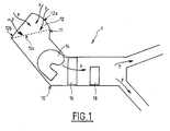
- FIG. 1 shows schematically an example of apparatus 1 for heating and / or air conditioning for a vehicle cabin, adapted according to the invention.
- This apparatus 1 comprises in particular a conduit 10, limited by an outer wall 11.
- This conduit is made of thermoplastic having a thickness of a few millimeters, two to three millimeters in the example.
- This conduit 10 forms, at its entrance, a box 12 air intake and housing, according to the direction of air flow (arrows F), a blower 14, an evaporator 16 and a radiator 18.
- the box air intake 12 houses a hinged shutter 20, drum-type in the example, formed of a hollow cylinder portion, about a quarter of cylinder, bounded by two lateral cheeks, 22 and 24, having substantially the shape of a portion of disc (a quarter disc) and two walls substantially rectangular 26 and 27.
- the shutter 20 is pivotally mounted about an axis xx ' passing through the air intake box 12 to, alternatively, come close an inlet 12a of external air (as more particularly illustrated by FIG. 4), or a screened entry 12b of recycled and filtered air from the passenger compartment (as more particularly illustrated in Figure 3).
- the box air intake 12 is also equipped with an air outlet 12c terminating to the ventilation duct 10, upstream of the blower 14 (FIG. 1), as well as two side walls 12d and 12e.
- the shutter 20 is rotated around a shaft 21 along an axis X'X by an electric gear motor 28.
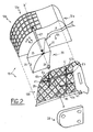
- This actuator 28 is fixed externally on the side wall 12d, or flank, of the box 12 at three distinct points 4a, 4b, 4c ( Figures 3 and 4).
- the side wall 12d is reinforced by a mesh of ribs of asymmetric profile 29, and each attachment point is formed in an intersection of this mesh. Studs in elevation 40a, 40b, 40c ensure the mounting of the gear motor 28 to the attachment points.
- the geared motor is in direct or indirect contact with the rotating shaft 21 of the shutter shutter 20.
- Nets 41 formed between the studs and the ribs 29 leading the studs reinforce the strength of the bindings.
- the plastic material of the wall 12d side, pads and reinforcement nets come from the same mold. Some nets may extend to join two studs.
- perforated zones Za, Zb, Zc, are made on the side wall 12d, immediate proximity of the studs respectively 40a, 40b, 40c motorcycle 28.
- These perforated zones are formed by recess of the units of constitutive material of the side wall bordered by ribs 29.
- the four units adjacent to the centering attachment points of each stud are hollowed out in the exemplary embodiment.
- a lower number of units (1 to 3) or even possibly greater than four, is or are cored.
- This mesh structure allows a significant reduction of vibratory noise created by the gear motor and can be troublesome for occupants of the vehicle, without loss of load or reduction of resistance mechanical of the air intake box 12.
- shutter 20 In a first position illustrated by FIG. shutter 20 is in its position of admission of the external air, that is to say it closes the arrival of recycled air 12b.
- the side cheek 24 of the shutter 20 closes substantially all the perforated zones Za of the air intake box 12 in communication with the recycled air.
- shutter 20 In a second position illustrated by FIG. shutter 20 is in its position of admission of recycled air from the passenger compartment by the arrival 12a, that is to say it closes the external air inlet 12a.
- the lateral cheek 24 substantially closes all the perforated zones Zb and Zc in communication with the external air.
- Peripheral joints can be provided around sealing against the outer wall of the air intake box 12, if necessary.
- the number of attachment points of the actuator can be greater than or less than three, and there may be multiple actuators sharing the same set of fixing points on the wall of the conduit to be protected, for example on the air intake box.
- the geared motor can be replaced by many others control means such as a stepper motor or a control system rack or notched pinion.
Landscapes
- Physics & Mathematics (AREA)
- Thermal Sciences (AREA)
- Engineering & Computer Science (AREA)
- Mechanical Engineering (AREA)
- Air-Conditioning For Vehicles (AREA)
- Body Structure For Vehicles (AREA)
Abstract
Description
- la figure 1, une vue en coupe d'un conduit de circulation d'air d'un appareil de chauffage et/ou de climatisation conforme à l'invention et comprenant en particulier une boíte d'admission d'air,
- la figure 2, une vue en perspective éclatée de la boíte d'admission d'air de la figure 1, muni d'un volet d'obturation et d'un actionneur,
- la figure 3, une vue de côté de la figure 2 avec le volet d'obturation dans une première position, et
- la figure 4, une vue de côté de la figure 2 avec le volet d'obturation dans une seconde position.
Claims (7)
- Appareil (1) de climatisation et/ou de chauffage pour habitacle de véhicule automobile comprenant au moins un conduit d'air (10) présentant une paroi externe (11) logeant un volet d'obturation (20) articulé autour d'un axe (X'X), ledit volet (20) étant commandé par un actionneur (28) fixé en plusieurs points (4a, 4b, 4c) sur une partie rigidifiée de la paroi (11), caractérisé en ce que ladite paroi rigidifiée (12d) présente au moins une zone ajourée (Za, Zb, Zc) dépourvue de matière à proximité immédiate d'au moins un point de fixation de l'actionneur (28) pour réduire la transmission des vibrations causées par le fonctionnement de l'actionneur.
- Appareil selon la revendication 1, dans lequel, la partie rigidifiée étant formée d'un maillage de nervures (29) délimitant des unités de matière de paroi (12d) et les points de fixation étant aux intersections de ce maillage, la partie ajourée formée par la ou les zones ajourées (Za, Zb, Zc) est constituée par les unités de matière entourant les points de fixation.
- Appareil selon la revendication 1 ou 2, dans lequel les nervures (29) sont asymétriques pour assurer une tenue mécanique aux points de fixation et éviter les modes vibratoires harmoniques.
- Appareil selon l'une quelconque des revendications précédentes, dans lequel l'actionneur (28) est relié à la paroi externe (11) du conduit (10) en au moins trois points distincts à l'aide de plots (40a, 40b, 40c) venant de moulage et renforcés par des filets (41).
- Appareil selon l'une quelconque des revendications précédentes, dans lequel le volet (20) masque sensiblement, par un flanc latéral (24), les zones ajourées d'une entrée d'air non souhaité, selon sa position angulaire.
- Appareil selon la revendication 5, dans lequel le volet (20) est du type tambour présentant une portion de cylindre limitée par des joues latérales (24, 25).
- Appareil selon l'une quelconque des revendications précédentes, dans lequel le conduit est une boíte d'admission d'air (12) placé en entrée de l'appareil, cette boíte présentant une entrée d'air externe (12a), une entrée d'air recyclé (12b), une sortie d'air (12c) et deux parois latérales (12d, 12e) dont l'une (12d) forme la paroi rigidifiée.
Applications Claiming Priority (2)
| Application Number | Priority Date | Filing Date | Title |
|---|---|---|---|
| FR0209996 | 2002-08-06 | ||
| FR0209996A FR2843336B1 (fr) | 2002-08-06 | 2002-08-06 | Appareil de climatisation et/ou de chauffage pour habitacle de vehicule automobile muni d'au moins un actionneur pour volet articule |
Publications (2)
| Publication Number | Publication Date |
|---|---|
| EP1388443A1 true EP1388443A1 (fr) | 2004-02-11 |
| EP1388443B1 EP1388443B1 (fr) | 2006-11-02 |
Family
ID=30129707
Family Applications (1)
| Application Number | Title | Priority Date | Filing Date |
|---|---|---|---|
| EP03016496A Expired - Lifetime EP1388443B1 (fr) | 2002-08-06 | 2003-07-22 | Appareil de climatisation et/ou de chauffage pour habitacle de véhicule automobile muni d'au moins un actionneur pour volet articulé |
Country Status (5)
| Country | Link |
|---|---|
| EP (1) | EP1388443B1 (fr) |
| AT (1) | ATE344155T1 (fr) |
| DE (1) | DE60309390T2 (fr) |
| ES (1) | ES2275979T3 (fr) |
| FR (1) | FR2843336B1 (fr) |
Cited By (1)
| Publication number | Priority date | Publication date | Assignee | Title |
|---|---|---|---|---|
| KR20170040831A (ko) * | 2015-10-05 | 2017-04-14 | 한온시스템 주식회사 | 차량용 공조 장치 |
Families Citing this family (1)
| Publication number | Priority date | Publication date | Assignee | Title |
|---|---|---|---|---|
| FR3097906B1 (fr) * | 2019-06-26 | 2021-06-04 | Valeo Systemes Thermiques | Dispositif de régulation d’un flux d’air pour une entrée d’air d’un véhicule automobile |
Citations (3)
| Publication number | Priority date | Publication date | Assignee | Title |
|---|---|---|---|---|
| DE8620239U1 (de) * | 1986-07-29 | 1986-09-25 | Bayerische Motoren Werke AG, 8000 München | Befestigungsanordnung für Elektro-Kleinmotoren, insbesondere für Schrittschalt-Getriebemotoren an Heiz- und/oder Klimaanlagen von Kraftfahrzeugen |
| EP1152154A1 (fr) * | 2000-04-25 | 2001-11-07 | Asmo Co., Ltd. | Support de moteur avec élements de connexion en direction radiale et oblique |
| EP1216862A2 (fr) * | 2000-12-20 | 2002-06-26 | Behr GmbH & Co. | Dispositif de guidage d'écoulements d'air dans les installations de chauffage ou de climatisation de véhicule |
-
2002
- 2002-08-06 FR FR0209996A patent/FR2843336B1/fr not_active Expired - Lifetime
-
2003
- 2003-07-22 AT AT03016496T patent/ATE344155T1/de not_active IP Right Cessation
- 2003-07-22 EP EP03016496A patent/EP1388443B1/fr not_active Expired - Lifetime
- 2003-07-22 ES ES03016496T patent/ES2275979T3/es not_active Expired - Lifetime
- 2003-07-22 DE DE60309390T patent/DE60309390T2/de not_active Expired - Lifetime
Patent Citations (3)
| Publication number | Priority date | Publication date | Assignee | Title |
|---|---|---|---|---|
| DE8620239U1 (de) * | 1986-07-29 | 1986-09-25 | Bayerische Motoren Werke AG, 8000 München | Befestigungsanordnung für Elektro-Kleinmotoren, insbesondere für Schrittschalt-Getriebemotoren an Heiz- und/oder Klimaanlagen von Kraftfahrzeugen |
| EP1152154A1 (fr) * | 2000-04-25 | 2001-11-07 | Asmo Co., Ltd. | Support de moteur avec élements de connexion en direction radiale et oblique |
| EP1216862A2 (fr) * | 2000-12-20 | 2002-06-26 | Behr GmbH & Co. | Dispositif de guidage d'écoulements d'air dans les installations de chauffage ou de climatisation de véhicule |
Cited By (1)
| Publication number | Priority date | Publication date | Assignee | Title |
|---|---|---|---|---|
| KR20170040831A (ko) * | 2015-10-05 | 2017-04-14 | 한온시스템 주식회사 | 차량용 공조 장치 |
Also Published As
| Publication number | Publication date |
|---|---|
| EP1388443B1 (fr) | 2006-11-02 |
| DE60309390T2 (de) | 2007-09-20 |
| ES2275979T3 (es) | 2007-06-16 |
| DE60309390D1 (de) | 2006-12-14 |
| ATE344155T1 (de) | 2006-11-15 |
| FR2843336B1 (fr) | 2006-01-20 |
| FR2843336A1 (fr) | 2004-02-13 |
Similar Documents
| Publication | Publication Date | Title |
|---|---|---|
| EP0856423B1 (fr) | Registre à volets multiples, notamment pour un système de climatisation de véhicule automobile | |
| WO2014150143A1 (fr) | Ensemble volet de grille | |
| FR2877271A1 (fr) | Aerateur de systeme de ventilation de l'habitacle d'un vehicule | |
| FR3032917A1 (fr) | Module de conditionnement d'air d'un habitacle de vehicule automobile | |
| EP2889168B1 (fr) | Dispositif de chauffage, ventilation et/ou climatisation | |
| WO2016192984A1 (fr) | Panneau de volets et véhicule automobile | |
| EP2243646B1 (fr) | Boîtier de traitement thermique pour le traitement thermique d'un flux d'air | |
| EP1388443B1 (fr) | Appareil de climatisation et/ou de chauffage pour habitacle de véhicule automobile muni d'au moins un actionneur pour volet articulé | |
| WO2019063905A1 (fr) | Pulseur d'air pour vehicule automobile | |
| FR3037868A1 (fr) | Dispositif de ventilation, chauffage et /ou climatisation d'un vehicule automobile | |
| FR2619438A3 (fr) | Dispositif de commande et de conduite de l'air sortant d'une installation de chauffage, d'aeration et de climatisation | |
| FR2846599A1 (fr) | Systeme de conditionnement d'air pour vehicules et son procede de fabrication | |
| FR3044604B1 (fr) | Boitier d'entree d'air et installation de chauffage, de ventilation et/ou de climatisation correspondante | |
| FR2671520A1 (fr) | Aerateur pour systemes de ventilation et de climatisation. | |
| EP3169541B1 (fr) | Volet d'une installation de chauffage, ventilation et/ou climatisation pour habitacle de vehicule automobile et installation associee | |
| FR2987787A1 (fr) | Installation de chauffage, ventilation et/ou climatisation pour un habitacle de vehicule automobile | |
| FR2883511A1 (fr) | Boitier d'admission d'air pour une installation de chauffage, ventilation et/ou climatisation d'un habitacle de vehicule automobile | |
| FR2959167A1 (fr) | Installation de traitement thermique d'un flux d'air | |
| EP2106941A1 (fr) | Appareil de chauffage, ventilation et/ou climatisation pour véhicule automobile. | |
| EP3990762A1 (fr) | Dispositif de regulation d'un flux d'air pour une entree d'air d'un vehicule automobile | |
| EP2240338B1 (fr) | Volet unique permettant la fermeture des sorties d'air centrales et latérales dans un système de climatisation de l'habitacle d'un véhicule automobile. | |
| FR2875452A1 (fr) | Module de chauffage, de ventilation et/ou de climatisation pour siege de vehicule | |
| FR2845946A1 (fr) | Appareil de chauffage, ventilation et/ou climatisation de l'habitacle d'un vehicule automobile comportant un volet de reglage d'air | |
| EP1484206B1 (fr) | Dispositif de chauffage-ventilation et/ou climatisation à encombrement réduit pour véhicule automobile | |
| EP1640196B1 (fr) | Elément structurant d'un habitacle de véhicule alimenté en air comportant un module de distribution sélective d'air |
Legal Events
| Date | Code | Title | Description |
|---|---|---|---|
| PUAI | Public reference made under article 153(3) epc to a published international application that has entered the european phase |
Free format text: ORIGINAL CODE: 0009012 |
|
| AK | Designated contracting states |
Kind code of ref document: A1 Designated state(s): AT BE BG CH CY CZ DE DK EE ES FI FR GB GR HU IE IT LI LU MC NL PT RO SE SI SK TR |
|
| AX | Request for extension of the european patent |
Extension state: AL LT LV MK |
|
| 17P | Request for examination filed |
Effective date: 20040518 |
|
| AKX | Designation fees paid |
Designated state(s): AT BE BG CH CY CZ DE DK EE ES FI FR GB GR HU IE IT LI LU MC NL PT RO SE SI SK TR |
|
| GRAP | Despatch of communication of intention to grant a patent |
Free format text: ORIGINAL CODE: EPIDOSNIGR1 |
|
| GRAS | Grant fee paid |
Free format text: ORIGINAL CODE: EPIDOSNIGR3 |
|
| GRAA | (expected) grant |
Free format text: ORIGINAL CODE: 0009210 |
|
| RAP1 | Party data changed (applicant data changed or rights of an application transferred) |
Owner name: VALEO SYSTEMES THERMIQUES |
|
| AK | Designated contracting states |
Kind code of ref document: B1 Designated state(s): AT BE BG CH CY CZ DE DK EE ES FI GB GR HU IE IT LI LU MC NL PT RO SE SI SK TR |
|
| PG25 | Lapsed in a contracting state [announced via postgrant information from national office to epo] |
Ref country code: NL Free format text: LAPSE BECAUSE OF FAILURE TO SUBMIT A TRANSLATION OF THE DESCRIPTION OR TO PAY THE FEE WITHIN THE PRESCRIBED TIME-LIMIT Effective date: 20061102 Ref country code: AT Free format text: LAPSE BECAUSE OF FAILURE TO SUBMIT A TRANSLATION OF THE DESCRIPTION OR TO PAY THE FEE WITHIN THE PRESCRIBED TIME-LIMIT Effective date: 20061102 Ref country code: SK Free format text: LAPSE BECAUSE OF FAILURE TO SUBMIT A TRANSLATION OF THE DESCRIPTION OR TO PAY THE FEE WITHIN THE PRESCRIBED TIME-LIMIT Effective date: 20061102 Ref country code: IE Free format text: LAPSE BECAUSE OF FAILURE TO SUBMIT A TRANSLATION OF THE DESCRIPTION OR TO PAY THE FEE WITHIN THE PRESCRIBED TIME-LIMIT Effective date: 20061102 Ref country code: SI Free format text: LAPSE BECAUSE OF FAILURE TO SUBMIT A TRANSLATION OF THE DESCRIPTION OR TO PAY THE FEE WITHIN THE PRESCRIBED TIME-LIMIT Effective date: 20061102 Ref country code: FI Free format text: LAPSE BECAUSE OF FAILURE TO SUBMIT A TRANSLATION OF THE DESCRIPTION OR TO PAY THE FEE WITHIN THE PRESCRIBED TIME-LIMIT Effective date: 20061102 Ref country code: RO Free format text: LAPSE BECAUSE OF FAILURE TO SUBMIT A TRANSLATION OF THE DESCRIPTION OR TO PAY THE FEE WITHIN THE PRESCRIBED TIME-LIMIT Effective date: 20061102 |
|
| REG | Reference to a national code |
Ref country code: GB Ref legal event code: FG4D Free format text: NOT ENGLISH |
|
| REG | Reference to a national code |
Ref country code: IE Ref legal event code: FG4D Free format text: LANGUAGE OF EP DOCUMENT: FRENCH |
|
| REG | Reference to a national code |
Ref country code: CH Ref legal event code: EP |
|
| REF | Corresponds to: |
Ref document number: 60309390 Country of ref document: DE Date of ref document: 20061214 Kind code of ref document: P |
|
| PG25 | Lapsed in a contracting state [announced via postgrant information from national office to epo] |
Ref country code: SE Free format text: LAPSE BECAUSE OF FAILURE TO SUBMIT A TRANSLATION OF THE DESCRIPTION OR TO PAY THE FEE WITHIN THE PRESCRIBED TIME-LIMIT Effective date: 20070202 Ref country code: BG Free format text: LAPSE BECAUSE OF FAILURE TO SUBMIT A TRANSLATION OF THE DESCRIPTION OR TO PAY THE FEE WITHIN THE PRESCRIBED TIME-LIMIT Effective date: 20070202 Ref country code: DK Free format text: LAPSE BECAUSE OF FAILURE TO SUBMIT A TRANSLATION OF THE DESCRIPTION OR TO PAY THE FEE WITHIN THE PRESCRIBED TIME-LIMIT Effective date: 20070202 |
|
| PG25 | Lapsed in a contracting state [announced via postgrant information from national office to epo] |
Ref country code: PT Free format text: LAPSE BECAUSE OF FAILURE TO SUBMIT A TRANSLATION OF THE DESCRIPTION OR TO PAY THE FEE WITHIN THE PRESCRIBED TIME-LIMIT Effective date: 20070402 |
|
| NLV1 | Nl: lapsed or annulled due to failure to fulfill the requirements of art. 29p and 29m of the patents act | ||
| GBV | Gb: ep patent (uk) treated as always having been void in accordance with gb section 77(7)/1977 [no translation filed] |
Effective date: 20061102 |
|
| REG | Reference to a national code |
Ref country code: ES Ref legal event code: FG2A Ref document number: 2275979 Country of ref document: ES Kind code of ref document: T3 |
|
| REG | Reference to a national code |
Ref country code: IE Ref legal event code: FD4D |
|
| PLBE | No opposition filed within time limit |
Free format text: ORIGINAL CODE: 0009261 |
|
| STAA | Information on the status of an ep patent application or granted ep patent |
Free format text: STATUS: NO OPPOSITION FILED WITHIN TIME LIMIT |
|
| 26N | No opposition filed |
Effective date: 20070803 |
|
| PG25 | Lapsed in a contracting state [announced via postgrant information from national office to epo] |
Ref country code: GB Free format text: LAPSE BECAUSE OF FAILURE TO SUBMIT A TRANSLATION OF THE DESCRIPTION OR TO PAY THE FEE WITHIN THE PRESCRIBED TIME-LIMIT Effective date: 20061102 |
|
| BERE | Be: lapsed |
Owner name: VALEO SYSTEMES THERMIQUES Effective date: 20070731 |
|
| REG | Reference to a national code |
Ref country code: CH Ref legal event code: PL |
|
| PG25 | Lapsed in a contracting state [announced via postgrant information from national office to epo] |
Ref country code: GR Free format text: LAPSE BECAUSE OF FAILURE TO SUBMIT A TRANSLATION OF THE DESCRIPTION OR TO PAY THE FEE WITHIN THE PRESCRIBED TIME-LIMIT Effective date: 20070203 Ref country code: LI Free format text: LAPSE BECAUSE OF NON-PAYMENT OF DUE FEES Effective date: 20070731 Ref country code: MC Free format text: LAPSE BECAUSE OF NON-PAYMENT OF DUE FEES Effective date: 20070731 Ref country code: CH Free format text: LAPSE BECAUSE OF NON-PAYMENT OF DUE FEES Effective date: 20070731 |
|
| PG25 | Lapsed in a contracting state [announced via postgrant information from national office to epo] |
Ref country code: BE Free format text: LAPSE BECAUSE OF NON-PAYMENT OF DUE FEES Effective date: 20070731 |
|
| PG25 | Lapsed in a contracting state [announced via postgrant information from national office to epo] |
Ref country code: EE Free format text: LAPSE BECAUSE OF FAILURE TO SUBMIT A TRANSLATION OF THE DESCRIPTION OR TO PAY THE FEE WITHIN THE PRESCRIBED TIME-LIMIT Effective date: 20061102 |
|
| PG25 | Lapsed in a contracting state [announced via postgrant information from national office to epo] |
Ref country code: LU Free format text: LAPSE BECAUSE OF NON-PAYMENT OF DUE FEES Effective date: 20070722 Ref country code: CY Free format text: LAPSE BECAUSE OF FAILURE TO SUBMIT A TRANSLATION OF THE DESCRIPTION OR TO PAY THE FEE WITHIN THE PRESCRIBED TIME-LIMIT Effective date: 20061102 |
|
| PG25 | Lapsed in a contracting state [announced via postgrant information from national office to epo] |
Ref country code: TR Free format text: LAPSE BECAUSE OF FAILURE TO SUBMIT A TRANSLATION OF THE DESCRIPTION OR TO PAY THE FEE WITHIN THE PRESCRIBED TIME-LIMIT Effective date: 20061102 Ref country code: HU Free format text: LAPSE BECAUSE OF FAILURE TO SUBMIT A TRANSLATION OF THE DESCRIPTION OR TO PAY THE FEE WITHIN THE PRESCRIBED TIME-LIMIT Effective date: 20070503 |
|
| PGFP | Annual fee paid to national office [announced via postgrant information from national office to epo] |
Ref country code: CZ Payment date: 20210622 Year of fee payment: 19 |
|
| PGFP | Annual fee paid to national office [announced via postgrant information from national office to epo] |
Ref country code: IT Payment date: 20210707 Year of fee payment: 19 |
|
| PGFP | Annual fee paid to national office [announced via postgrant information from national office to epo] |
Ref country code: ES Payment date: 20210812 Year of fee payment: 19 |
|
| PGFP | Annual fee paid to national office [announced via postgrant information from national office to epo] |
Ref country code: DE Payment date: 20220624 Year of fee payment: 20 |
|
| PG25 | Lapsed in a contracting state [announced via postgrant information from national office to epo] |
Ref country code: CZ Free format text: LAPSE BECAUSE OF NON-PAYMENT OF DUE FEES Effective date: 20220722 |
|
| P01 | Opt-out of the competence of the unified patent court (upc) registered |
Effective date: 20230528 |
|
| REG | Reference to a national code |
Ref country code: DE Ref legal event code: R071 Ref document number: 60309390 Country of ref document: DE |
|
| PG25 | Lapsed in a contracting state [announced via postgrant information from national office to epo] |
Ref country code: IT Free format text: LAPSE BECAUSE OF NON-PAYMENT OF DUE FEES Effective date: 20220722 |
|
| REG | Reference to a national code |
Ref country code: ES Ref legal event code: FD2A Effective date: 20230831 |
|
| PG25 | Lapsed in a contracting state [announced via postgrant information from national office to epo] |
Ref country code: ES Free format text: LAPSE BECAUSE OF NON-PAYMENT OF DUE FEES Effective date: 20220723 |