EP1388331A1 - Liquefaction handpiece tip - Google Patents
Liquefaction handpiece tip Download PDFInfo
- Publication number
- EP1388331A1 EP1388331A1 EP03077109A EP03077109A EP1388331A1 EP 1388331 A1 EP1388331 A1 EP 1388331A1 EP 03077109 A EP03077109 A EP 03077109A EP 03077109 A EP03077109 A EP 03077109A EP 1388331 A1 EP1388331 A1 EP 1388331A1
- Authority
- EP
- European Patent Office
- Prior art keywords
- tip
- outer tube
- inner tube
- annular gap
- handpiece
- Prior art date
- Legal status (The legal status is an assumption and is not a legal conclusion. Google has not performed a legal analysis and makes no representation as to the accuracy of the status listed.)
- Granted
Links
- 239000012530 fluid Substances 0.000 claims abstract description 25
- 238000010276 construction Methods 0.000 abstract description 5
- 239000000243 solution Substances 0.000 description 7
- 238000000034 method Methods 0.000 description 5
- 208000002177 Cataract Diseases 0.000 description 4
- 239000013078 crystal Substances 0.000 description 4
- 239000000463 material Substances 0.000 description 4
- 210000004087 cornea Anatomy 0.000 description 3
- 238000002347 injection Methods 0.000 description 3
- 239000007924 injection Substances 0.000 description 3
- 230000002262 irrigation Effects 0.000 description 3
- 238000003973 irrigation Methods 0.000 description 3
- 238000001356 surgical procedure Methods 0.000 description 3
- FAPWRFPIFSIZLT-UHFFFAOYSA-M Sodium chloride Chemical compound [Na+].[Cl-] FAPWRFPIFSIZLT-UHFFFAOYSA-M 0.000 description 2
- 210000001525 retina Anatomy 0.000 description 2
- 239000011780 sodium chloride Substances 0.000 description 2
- 238000001816 cooling Methods 0.000 description 1
- 230000007812 deficiency Effects 0.000 description 1
- 230000003292 diminished effect Effects 0.000 description 1
- 201000010099 disease Diseases 0.000 description 1
- 208000037265 diseases, disorders, signs and symptoms Diseases 0.000 description 1
- 230000001804 emulsifying effect Effects 0.000 description 1
- 238000011010 flushing procedure Methods 0.000 description 1
- 238000010438 heat treatment Methods 0.000 description 1
- 238000011065 in-situ storage Methods 0.000 description 1
- 238000012986 modification Methods 0.000 description 1
- 230000004048 modification Effects 0.000 description 1
- 238000005086 pumping Methods 0.000 description 1
- 210000003786 sclera Anatomy 0.000 description 1
- XLYOFNOQVPJJNP-UHFFFAOYSA-N water Substances O XLYOFNOQVPJJNP-UHFFFAOYSA-N 0.000 description 1
Images
Classifications
-
- A—HUMAN NECESSITIES
- A61—MEDICAL OR VETERINARY SCIENCE; HYGIENE
- A61F—FILTERS IMPLANTABLE INTO BLOOD VESSELS; PROSTHESES; DEVICES PROVIDING PATENCY TO, OR PREVENTING COLLAPSING OF, TUBULAR STRUCTURES OF THE BODY, e.g. STENTS; ORTHOPAEDIC, NURSING OR CONTRACEPTIVE DEVICES; FOMENTATION; TREATMENT OR PROTECTION OF EYES OR EARS; BANDAGES, DRESSINGS OR ABSORBENT PADS; FIRST-AID KITS
- A61F9/00—Methods or devices for treatment of the eyes; Devices for putting-in contact lenses; Devices to correct squinting; Apparatus to guide the blind; Protective devices for the eyes, carried on the body or in the hand
- A61F9/007—Methods or devices for eye surgery
- A61F9/00736—Instruments for removal of intra-ocular material or intra-ocular injection, e.g. cataract instruments
Definitions
- This invention relates generally to the field of cataract surgery and more particularly to a handpiece tip for practicing the liquefaction technique of cataract removal.
- the human eye in its simplest terms functions to provide vision by transmitting light through a clear outer portion called the cornea, and focusing the image by way of the lens onto the retina.
- the quality of the focused image depends on many factors including the size and shape of the eye, and the transparency of the cornea and lens.
- IOL intraocular lens
- phacoemulsification In the United States, the majority of cataractous lenses are removed by a surgical technique called phacoemulsification. During this procedure, a thin phacoemulsification cutting tip is inserted into the diseased lens and vibrated ultrasonically. The vibrating cutting tip liquifies or emulsifies the lens so that the lens may be aspirated out of the eye. The diseased lens, once removed, is replaced by an artificial lens.
- a typical ultrasonic surgical device suitable for ophthalmic procedures consists of an ultrasonically driven handpiece, an attached cutting tip, and irrigating sleeve and an electronic control console.
- the handpiece assembly is attached to the control console by an electric cable and flexible tubes. Through the electric cable, the console varies the power level transmitted by the handpiece to the attached cutting tip and the flexible tubes supply irrigation fluid to and draw aspiration fluid from the eye through the handpiece assembly.
- the operative part of the handpiece is a centrally located, hollow resonating bar or horn directly attached to a set of piezoelectric crystals.
- the crystals supply the required ultrasonic vibration needed to drive both the horn and the attached cutting tip during phacoemulsification and are controlled by the console.
- the crystal/horn assembly is suspended within the hollow body or shell of the handpiece by flexible mountings.
- the handpiece body terminates in a reduced diameter portion or nosecone at the body's distal end.
- the nosecone is externally threaded to accept the irrigation sleeve.
- the horn bore is internally threaded at its distal end to receive the external threads of the cutting tip.
- the irrigation sleeve also has an internally threaded bore that is screwed onto the external threads of the nosecone.
- the cutting tip is adjusted so that the tip projects only a predetermined amount past the open end of the irrigating sleeve.
- Ultrasonic handpieces and cutting tips are more fully described in U.S. Pat. Nos. 3,589,363; 4,223,676; 4,246,902; 4,493,694; 4,515,583; 4,589,415; 4,609,368; 4,869,715; 4,922,902; 4,989,583; 5,154,694 and 5,359,996.
- the ends of the cutting tip and irrigating sleeve are inserted into a small incision of predetermined width in the cornea, sclera, or other location.
- the cutting tip is ultrasonically vibrated along its longitudinal axis within the irrigating sleeve by the crystal-driven ultrasonic horn, thereby emulsifying the selected tissue in situ.
- the hollow bore of the cutting tip communicates with the bore in the horn that in turn communicates with the aspiration line from the handpiece to the console.
- a reduced pressure or vacuum source in the console draws or aspirates the emulsified tissue from the eye through the open end of the cutting tip, the cutting tip and horn bores and the aspiration line and into a collection device.
- the aspiration of emulsified tissue is aided by a saline flushing solution or irrigant that is injected into the surgical site through the small annular gap between the inside surface of the irrigating sleeve and the cutting tip.
- U.S. Patent No. 5,885,243 discloses a handpiece having a separate pumping mechanism and resistive heating element. Such a structure adds unnecessary complexity to the handpiece.
- the present invention provides a liquefaction tip in accordance with the claim which follows.
- the invention improves on the prior art by providing a surgical liquefaction tip having an angled concave rim defining an arcuate or scalloped distal end.
- Such a construction allows the heated pulses of fluid produced by the liquefaction handpiece to strike the lens without being allowed to directly exit the tip.
- one objective of the present invention is to provide a liquefaction tip for delivering pulses of fluid directly against the lens.
- Another objective of the present invention is to provide a liquefaction tip for delivering pulses of fluid that do not directly enter the eye.
- prior art liquefaction tip 10 generally consists of outer tube 12 surrounding and coaxial with inner tube 14.
- a distal portionof outer tube 12 is flared or belled so as to allow nozzle 18 to be inserted between outer tube 12 and inner tube 14.
- Nozzle 18 contains fluid channel 20 that communicates with orifice 22.
- Nozzle 18 seals annular gap 24 between outer tube 12 and inner tube 14. Pressurized fluid flowing down annular gap 24 is forced into fluid channel 20, out orifice 22 and against inner tube 14 near distal tip 16.
- Such a construction prevents pressurized fluid from directly entering the eye, however, due to the straight configuration and angle of rim 17, lens material is restricted from entering outer tube 12 and being directly exposed to the fluid jet exiting orifice 22.
- tip 110 of the present invention generally includes outer tube 112 surrounding and coaxial with inner tube 114.
- a distal portion of outer tube 112 is flared or belled so as to allow nozzle 118 to be inserted between outer tube 112 and inner tube 114.
- Nozzle 118 contains fluid channel 120 that communicates with orifice 122.
- Nozzle 118 seals annular gap 124 between outer tube 112 and inner tube 114. Pressurized fluid flowing down annular gap 124 is forced into fluid channel 120, out orifice 122 and against inner tube 114 near distal tip 116.
- Rim 117 is cut in a concave or inwardly arcuate shape. Such a construction allows pieces of lens material 200 to enter distal tip 116 and be exposed directly to the fluid jet exiting orifice 122, as best seen in FIG. 3.
Abstract
Description
- This invention relates generally to the field of cataract surgery and more particularly to a handpiece tip for practicing the liquefaction technique of cataract removal.
- The human eye in its simplest terms functions to provide vision by transmitting light through a clear outer portion called the cornea, and focusing the image by way of the lens onto the retina. The quality of the focused image depends on many factors including the size and shape of the eye, and the transparency of the cornea and lens.
- When age or disease causes the lens to become less transparent, vision deteriorates because of the diminished light which can be transmitted to the retina. This deficiency in the lens of the eye is medically known as a cataract. An accepted treatment for this condition is surgical removal of the lens and replacement of the lens function by an artificial intraocular lens (IOL).
- In the United States, the majority of cataractous lenses are removed by a surgical technique called phacoemulsification. During this procedure, a thin phacoemulsification cutting tip is inserted into the diseased lens and vibrated ultrasonically. The vibrating cutting tip liquifies or emulsifies the lens so that the lens may be aspirated out of the eye. The diseased lens, once removed, is replaced by an artificial lens.
- A typical ultrasonic surgical device suitable for ophthalmic procedures consists of an ultrasonically driven handpiece, an attached cutting tip, and irrigating sleeve and an electronic control console. The handpiece assembly is attached to the control console by an electric cable and flexible tubes. Through the electric cable, the console varies the power level transmitted by the handpiece to the attached cutting tip and the flexible tubes supply irrigation fluid to and draw aspiration fluid from the eye through the handpiece assembly.
- The operative part of the handpiece is a centrally located, hollow resonating bar or horn directly attached to a set of piezoelectric crystals. The crystals supply the required ultrasonic vibration needed to drive both the horn and the attached cutting tip during phacoemulsification and are controlled by the console. The crystal/horn assembly is suspended within the hollow body or shell of the handpiece by flexible mountings. The handpiece body terminates in a reduced diameter portion or nosecone at the body's distal end. The nosecone is externally threaded to accept the irrigation sleeve. Likewise, the horn bore is internally threaded at its distal end to receive the external threads of the cutting tip. The irrigation sleeve also has an internally threaded bore that is screwed onto the external threads of the nosecone. The cutting tip is adjusted so that the tip projects only a predetermined amount past the open end of the irrigating sleeve. Ultrasonic handpieces and cutting tips are more fully described in U.S. Pat. Nos. 3,589,363; 4,223,676; 4,246,902; 4,493,694; 4,515,583; 4,589,415; 4,609,368; 4,869,715; 4,922,902; 4,989,583; 5,154,694 and 5,359,996.
- In use, the ends of the cutting tip and irrigating sleeve are inserted into a small incision of predetermined width in the cornea, sclera, or other location. The cutting tip is ultrasonically vibrated along its longitudinal axis within the irrigating sleeve by the crystal-driven ultrasonic horn, thereby emulsifying the selected tissue in situ. The hollow bore of the cutting tip communicates with the bore in the horn that in turn communicates with the aspiration line from the handpiece to the console. A reduced pressure or vacuum source in the console draws or aspirates the emulsified tissue from the eye through the open end of the cutting tip, the cutting tip and horn bores and the aspiration line and into a collection device. The aspiration of emulsified tissue is aided by a saline flushing solution or irrigant that is injected into the surgical site through the small annular gap between the inside surface of the irrigating sleeve and the cutting tip.
- Recently, a new cataract removal technique has been developed that involves the injection of hot (approximately 45°C to 105°C) water or saline to liquefy or gellate the hard lens nucleus, thereby making it possible to aspirate the liquefied lens from the eye. Aspiration is conducted concurrently with the injection of the heated solution and the injection of a relatively cool solution, thereby quickly cooling and removing the heated solution. This technique is more fully described in U.S. Patent No. 5,616,120 (Andrew, et al.). The apparatus disclosed in the publication, however, heats the solution separately from the surgical handpiece. Temperature control of the heated solution can be difficult because the fluid tubes feeding the handpiece typically are up to two meters long, and the heated solution can cool considerably as it travels down the length of the tube.
- U.S. Patent No. 5,885,243 (Capetan, et al.) discloses a handpiece having a separate pumping mechanism and resistive heating element. Such a structure adds unnecessary complexity to the handpiece.
- U.S. Patent Nos. 5,989,212, 5,997,499, 6,110,162, 6,179,805, 6,196,989, 6,206,848, 6,287,274, 6,315,755, 6,331,171 and 6,398,7596 , all disclose various types of liquefaction handpieces and tips. These prior art tips do not allow the high pressure fluid stream to contact the cataractous material directly without leaving the tip and exposing the internal structures of the eye to the high pressure fluid stream.
- Therefore, a need continues to exist for a liquefaction tip that allows the material being removed to be directly exposed to the high pressure fluid while preventing the remaining eye structures from being exposed to the high pressure fluid stream.
- The present invention provides a liquefaction tip in accordance with the claim which follows. The invention improves on the prior art by providing a surgical liquefaction tip having an angled concave rim defining an arcuate or scalloped distal end. Such a construction allows the heated pulses of fluid produced by the liquefaction handpiece to strike the lens without being allowed to directly exit the tip.
- Accordingly, one objective of the present invention is to provide a liquefaction tip for delivering pulses of fluid directly against the lens.
- Another objective of the present invention is to provide a liquefaction tip for delivering pulses of fluid that do not directly enter the eye.
- These and other advantages and objectives of the present invention will become apparent from the detailed description and claims that follow.
-
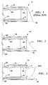
- FIG. 1 is a partial cross-sectional view of a prior art liquefaction handpiece tip.
- FIG. 2 is a partial cross-sectional view of the liquefaction handpiece tip of the present invention.
- FIG. 3 is a partial cross-sectional view of the liquefaction handpiece tip of the present invention similar to FIG. 2, but illustrating the location of the lens during use.
-
- As best seen in FIG. 1, prior
art liquefaction tip 10 generally consists ofouter tube 12 surrounding and coaxial withinner tube 14. A distal portionofouter tube 12 is flared or belled so as to allownozzle 18 to be inserted betweenouter tube 12 andinner tube 14.Nozzle 18 containsfluid channel 20 that communicates withorifice 22.Nozzle 18 sealsannular gap 24 betweenouter tube 12 andinner tube 14. Pressurized fluid flowing downannular gap 24 is forced intofluid channel 20, outorifice 22 and againstinner tube 14 neardistal tip 16. Such a construction prevents pressurized fluid from directly entering the eye, however, due to the straight configuration and angle ofrim 17, lens material is restricted from enteringouter tube 12 and being directly exposed to the fluidjet exiting orifice 22. - As best seen in FIG. 2,
tip 110 of the present invention generally includesouter tube 112 surrounding and coaxial withinner tube 114. A distal portion ofouter tube 112 is flared or belled so as to allownozzle 118 to be inserted betweenouter tube 112 andinner tube 114.Nozzle 118 containsfluid channel 120 that communicates withorifice 122.Nozzle 118 sealsannular gap 124 betweenouter tube 112 andinner tube 114. Pressurized fluid flowing downannular gap 124 is forced intofluid channel 120, outorifice 122 and againstinner tube 114 neardistal tip 116. Such a construction prevents pressurized fluid from directly entering the eye.Rim 117 is cut in a concave or inwardly arcuate shape. Such a construction allows pieces oflens material 200 to enterdistal tip 116 and be exposed directly to the fluidjet exiting orifice 122, as best seen in FIG. 3. - This description is given for purposes of illustration and explanation. It will be apparent to those skilled in the relevant art that changes and modifications may be made to the invention described above without departing from its scope For example, it will be recognized by those skilled in the art that the present invention may be combined with ultrasonic and/or rotating cutting tips to enhance performance.
Claims (1)
- A tip (110) for a liquefaction handpiece, comprising;characterized in that said rim (117) is formed with a concave configuration.a) an inner tube (114) coaxially mounted within an outer tube (112) so as to form an annular gap (124) between the inner tube and the outer tube, the outer tube defining an angled rim having a distal tip (116);b) a nozzle (118) at a distal end of the annular gap, inserted between the outer tube and the inner tube;c) at least one discharge orifice (122) in the nozzle, the orifice in fluid communication with the annular gap, such that a fluid jet exiting the orifice is directed against the inner tube near said distal tip,
Priority Applications (1)
| Application Number | Priority Date | Filing Date | Title |
|---|---|---|---|
| DK03077109T DK1388331T3 (en) | 2002-08-08 | 2003-07-04 | Smelting Handset Peak |
Applications Claiming Priority (2)
| Application Number | Priority Date | Filing Date | Title |
|---|---|---|---|
| US214623 | 2000-06-28 | ||
| US10/214,623 US20040030349A1 (en) | 2002-08-08 | 2002-08-08 | Liquefaction handpiece tip |
Publications (2)
| Publication Number | Publication Date |
|---|---|
| EP1388331A1 true EP1388331A1 (en) | 2004-02-11 |
| EP1388331B1 EP1388331B1 (en) | 2004-12-22 |
Family
ID=30443724
Family Applications (1)
| Application Number | Title | Priority Date | Filing Date |
|---|---|---|---|
| EP03077109A Expired - Lifetime EP1388331B1 (en) | 2002-08-08 | 2003-07-04 | Liquefaction handpiece tip |
Country Status (14)
| Country | Link |
|---|---|
| US (1) | US20040030349A1 (en) |
| EP (1) | EP1388331B1 (en) |
| JP (1) | JP2004065991A (en) |
| AR (1) | AR040587A1 (en) |
| AT (1) | ATE285211T1 (en) |
| AU (1) | AU2003231644A1 (en) |
| BR (1) | BR0302658A (en) |
| CA (1) | CA2434262A1 (en) |
| DE (1) | DE60300236T2 (en) |
| DK (1) | DK1388331T3 (en) |
| ES (1) | ES2235141T3 (en) |
| IL (1) | IL156782A0 (en) |
| MX (1) | MXPA03006676A (en) |
| PT (1) | PT1388331E (en) |
Cited By (2)
| Publication number | Priority date | Publication date | Assignee | Title |
|---|---|---|---|---|
| EP1759675A1 (en) * | 2005-08-29 | 2007-03-07 | Alcon, Inc. | Nozzle for a surgical irrigating handpiece |
| US7967799B2 (en) | 2005-03-16 | 2011-06-28 | Alcon, Inc. | Liquefaction handpiece tip |
Families Citing this family (18)
| Publication number | Priority date | Publication date | Assignee | Title |
|---|---|---|---|---|
| US7931611B2 (en) * | 2005-03-23 | 2011-04-26 | Misonix, Incorporated | Ultrasonic wound debrider probe and method of use |
| US9232959B2 (en) | 2007-01-02 | 2016-01-12 | Aquabeam, Llc | Multi fluid tissue resection methods and devices |
| WO2009111736A1 (en) | 2008-03-06 | 2009-09-11 | Aquabeam Llc | Tissue ablation and cautery with optical energy carried in fluid stream |
| US9504604B2 (en) | 2011-12-16 | 2016-11-29 | Auris Surgical Robotics, Inc. | Lithotripsy eye treatment |
| EP2819599B1 (en) | 2012-02-29 | 2018-05-23 | Procept Biorobotics Corporation | Automated image-guided tissue resection and treatment |
| US10383765B2 (en) | 2012-04-24 | 2019-08-20 | Auris Health, Inc. | Apparatus and method for a global coordinate system for use in robotic surgery |
| US10231867B2 (en) | 2013-01-18 | 2019-03-19 | Auris Health, Inc. | Method, apparatus and system for a water jet |
| US9867635B2 (en) | 2013-03-08 | 2018-01-16 | Auris Surgical Robotics, Inc. | Method, apparatus and system for a water jet |
| US10149720B2 (en) | 2013-03-08 | 2018-12-11 | Auris Health, Inc. | Method, apparatus, and a system for facilitating bending of an instrument in a surgical or medical robotic environment |
| US10080576B2 (en) | 2013-03-08 | 2018-09-25 | Auris Health, Inc. | Method, apparatus, and a system for facilitating bending of an instrument in a surgical or medical robotic environment |
| US9867636B2 (en) | 2013-03-15 | 2018-01-16 | The Regents Of The University Of California | Method, apparatus, and a system for a water jet |
| WO2014201165A1 (en) | 2013-06-11 | 2014-12-18 | Auris Surgical Robotics, Inc. | System for robotic assisted cataract surgery |
| US10426661B2 (en) | 2013-08-13 | 2019-10-01 | Auris Health, Inc. | Method and apparatus for laser assisted cataract surgery |
| EP3060157B1 (en) | 2013-10-24 | 2019-12-11 | Auris Health, Inc. | System for robotic-assisted endolumenal surgery |
| US9980785B2 (en) | 2013-10-24 | 2018-05-29 | Auris Health, Inc. | Instrument device manipulator with surgical tool de-articulation |
| US9788910B2 (en) | 2014-07-01 | 2017-10-17 | Auris Surgical Robotics, Inc. | Instrument-mounted tension sensing mechanism for robotically-driven medical instruments |
| US10792464B2 (en) | 2014-07-01 | 2020-10-06 | Auris Health, Inc. | Tool and method for using surgical endoscope with spiral lumens |
| AU2016321332B2 (en) | 2015-09-09 | 2020-10-08 | Auris Health, Inc. | Instrument device manipulator for a surgical robotics system |
Citations (3)
| Publication number | Priority date | Publication date | Assignee | Title |
|---|---|---|---|---|
| US4689040A (en) * | 1985-04-29 | 1987-08-25 | Thompson Robert J | Tip for a phacoemulsification needle |
| WO2001030284A1 (en) * | 1999-10-28 | 2001-05-03 | Alcon Laboratories, Inc. | Liquefracture handpiece |
| US20020077585A1 (en) * | 1998-06-04 | 2002-06-20 | Glenn Sussman | Liquefracture handpiece tip |
Family Cites Families (76)
| Publication number | Priority date | Publication date | Assignee | Title |
|---|---|---|---|---|
| US554155A (en) * | 1896-02-04 | Hose-band | ||
| US1493450A (en) * | 1923-05-05 | 1924-05-06 | Richardson Elizabeth | Saline heating apparatus |
| US3606678A (en) * | 1968-05-28 | 1971-09-21 | Bell Telephone Labor Inc | Method for making a ferreed switch having printed circuit board wiring |
| US3589263A (en) * | 1968-07-26 | 1971-06-29 | Du Pont | Photographic processing apparatus |
| US3818913A (en) * | 1972-08-30 | 1974-06-25 | M Wallach | Surgical apparatus for removal of tissue |
| US3930505A (en) * | 1974-06-24 | 1976-01-06 | Hydro Pulse Corporation | Surgical apparatus for removal of tissue |
| US3994297A (en) * | 1974-12-09 | 1976-11-30 | Kopf J David | Ophthalmic instrument |
| US4024868A (en) * | 1975-02-03 | 1977-05-24 | Robert W Williams | Permanent aneurysm clamp |
| US4265618A (en) * | 1977-09-09 | 1981-05-05 | Solar Energy Technology, Inc. | Electrically heated endodontic syringe for injecting thermoplastic material into a root canal cavity |
| US4246902A (en) * | 1978-03-10 | 1981-01-27 | Miguel Martinez | Surgical cutting instrument |
| US4223678A (en) * | 1978-05-03 | 1980-09-23 | Mieczyslaw Mirowski | Arrhythmia recorder for use with an implantable defibrillator |
| US4249899A (en) * | 1979-02-14 | 1981-02-10 | A-Dec, Inc. | Warm water dental syringe |
| US4301802A (en) * | 1980-03-17 | 1981-11-24 | Stanley Poler | Cauterizing tool for ophthalmological surgery |
| US4493694A (en) * | 1980-10-17 | 1985-01-15 | Cooper Lasersonics, Inc. | Surgical pre-aspirator |
| US4517977A (en) * | 1981-07-24 | 1985-05-21 | Unisearch Limited | Co-axial tube surgical infusion/suction cutter tip |
| US4489984A (en) * | 1982-04-22 | 1984-12-25 | Mobil Oil Corporation | In-situ uranium leaching process |
| JPS59200644A (en) * | 1983-04-27 | 1984-11-14 | オリンパス光学工業株式会社 | Surgical incision instrument |
| US4515583A (en) * | 1983-10-17 | 1985-05-07 | Coopervision, Inc. | Operative elliptical probe for ultrasonic surgical instrument and method of its use |
| US4577629A (en) * | 1983-10-28 | 1986-03-25 | Coopervision, Inc. | Surgical cutting instrument for ophthalmic surgery |
| JPS61501067A (en) * | 1984-01-30 | 1986-05-29 | シユレ−ゲル・ハンス−ヨアキム | Living eye lens capsule anterior wall drilling device |
| US4570632A (en) * | 1984-03-16 | 1986-02-18 | Woods Randall L | Cystotome for eye surgery and method of opening lens capsule |
| US4609368A (en) * | 1984-08-22 | 1986-09-02 | Dotson Robert S Jun | Pneumatic ultrasonic surgical handpiece |
| US4589415A (en) * | 1984-08-31 | 1986-05-20 | Haaga John R | Method and system for fragmenting kidney stones |
| US4634420A (en) * | 1984-10-31 | 1987-01-06 | United Sonics Incorporated | Apparatus and method for removing tissue mass from an organism |
| US4922902A (en) * | 1986-05-19 | 1990-05-08 | Valleylab, Inc. | Method for removing cellular material with endoscopic ultrasonic aspirator |
| US4674502A (en) * | 1985-09-27 | 1987-06-23 | Coopervision, Inc. | Intraocular surgical instrument |
| US4634419A (en) * | 1985-12-13 | 1987-01-06 | Cooper Lasersonics, Inc. | Angulated ultrasonic surgical handpieces and method for their production |
| US4989588A (en) * | 1986-03-10 | 1991-02-05 | Olympus Optical Co., Ltd. | Medical treatment device utilizing ultrasonic wave |
| US4753234A (en) * | 1986-11-03 | 1988-06-28 | Miguel Martinez | Surgical cutting instrument having a offset probe for ophthalmic surgery |
| EP0285962B1 (en) * | 1987-04-10 | 1993-02-17 | Siemens Aktiengesellschaft | Control circuit for a hf chirurgical apparatus |
| SE458821B (en) * | 1987-09-04 | 1989-05-16 | Swedemed Ab | ULTRASOUND KNIFE |
| IL83826A (en) * | 1987-09-08 | 1991-03-10 | Inventor S Funding Corp Ltd | Plastic mouthpiece for simulated smoking |
| US4986827A (en) * | 1987-11-05 | 1991-01-22 | Nestle S.A. | Surgical cutting instrument with reciprocating inner cutter |
| US4909249A (en) * | 1987-11-05 | 1990-03-20 | The Cooper Companies, Inc. | Surgical cutting instrument |
| US4869715A (en) * | 1988-04-21 | 1989-09-26 | Sherburne Fred S | Ultrasonic cone and method of construction |
| US4989583A (en) * | 1988-10-21 | 1991-02-05 | Nestle S.A. | Ultrasonic cutting tip assembly |
| US4898298A (en) * | 1989-03-29 | 1990-02-06 | Norris Annie B | Flying insect container guard |
| US5154694A (en) * | 1989-06-06 | 1992-10-13 | Kelman Charles D | Tissue scraper device for medical use |
| US5019035A (en) * | 1989-06-07 | 1991-05-28 | Alcon Surgical, Inc. | Cutting assembly for surgical cutting instrument |
| US5226910A (en) * | 1989-07-05 | 1993-07-13 | Kabushiki Kaisha Topcon | Surgical cutter |
| US5106364A (en) * | 1989-07-07 | 1992-04-21 | Kabushiki Kaisha Topcon | Surgical cutter |
| US5624392A (en) * | 1990-05-11 | 1997-04-29 | Saab; Mark A. | Heat transfer catheters and methods of making and using same |
| US5250065A (en) * | 1990-09-11 | 1993-10-05 | Mectra Labs, Inc. | Disposable lavage tip assembly |
| US5285795A (en) * | 1991-09-12 | 1994-02-15 | Surgical Dynamics, Inc. | Percutaneous discectomy system having a bendable discectomy probe and a steerable cannula |
| US5275607A (en) * | 1991-09-23 | 1994-01-04 | Visionary Medical, Inc. | Intraocular surgical scissors |
| US5891095A (en) * | 1993-05-10 | 1999-04-06 | Arthrocare Corporation | Electrosurgical treatment of tissue in electrically conductive fluid |
| US6565584B1 (en) * | 1992-04-10 | 2003-05-20 | Addition Technology, Inc. | Device and method for inserting a biocompatible material into the corneal stroma |
| US5261923A (en) * | 1992-04-23 | 1993-11-16 | Soares Christopher J | Method and apparatus for continuous circular capsulorehexis |
| US5308673A (en) * | 1992-05-07 | 1994-05-03 | Minnesota Mining And Manufacturing Company | Stitchbonded absorbent articles and method of making same |
| US5322504A (en) * | 1992-05-07 | 1994-06-21 | United States Surgical Corporation | Method and apparatus for tissue excision and removal by fluid jet |
| US5284472A (en) * | 1992-10-30 | 1994-02-08 | Allergan, Inc. | Vitreous cutter |
| US5423330A (en) * | 1993-03-10 | 1995-06-13 | The University Of Miami | Capsule suction punch instrument and method of use |
| CA2127637C (en) * | 1993-07-26 | 2006-01-03 | Scott Bair | Fluid jet surgical cutting tool |
| US5591184A (en) * | 1994-10-13 | 1997-01-07 | Sentinel Medical, Inc. | Fluid jet surgical cutting instrument |
| US5616120A (en) * | 1995-02-06 | 1997-04-01 | Andrew; Mark S. | Method and apparatus for lenticular liquefaction and aspiration |
| US5653692A (en) * | 1995-09-07 | 1997-08-05 | Innerdyne Medical, Inc. | Method and system for direct heating of fluid solution in a hollow body organ |
| US5624393A (en) * | 1996-01-03 | 1997-04-29 | Diamond; Eric L. | Irrigation system for surgical instruments |
| US5669923A (en) * | 1996-01-24 | 1997-09-23 | Gordon; Mark G. | Anterior capsulotomy device and procedure |
| US5776719A (en) * | 1997-07-07 | 1998-07-07 | Mercury Diagnostics, Inc. | Diagnostic compositions and devices utilizing same |
| PL191903B1 (en) * | 1996-07-25 | 2006-07-31 | Ipcor Nv | Method of deoxidising and melting metals and apparatus for preheating charge for deoxidising and melting processes |
| US5885243A (en) * | 1996-12-11 | 1999-03-23 | Alcon Laboratories, Inc. | Liquefaction handpiece |
| US5766194A (en) * | 1996-12-23 | 1998-06-16 | Georgia Skin And Cancer Clinic, Pc | Surgical apparatus for tissue removal |
| US6148380A (en) * | 1997-01-02 | 2000-11-14 | Intel Corporation | Method and apparatus for controlling data transfer between a synchronous DRAM-type memory and a system bus |
| US5879347A (en) * | 1997-04-25 | 1999-03-09 | Gynecare, Inc. | Apparatus for controlled thermal treatment of tissue |
| US6139571A (en) * | 1997-07-09 | 2000-10-31 | Fuller Research Corporation | Heated fluid surgical instrument |
| US5993408A (en) * | 1997-10-03 | 1999-11-30 | Allergan Sales, Inc. | Thin tip phaco needle |
| US6039715A (en) * | 1998-05-11 | 2000-03-21 | Mackool; Richard J. | Angulated phacoemulsification needle whose outer surface converges and inner channel narrows |
| US6315755B1 (en) * | 1998-06-04 | 2001-11-13 | Alcon Manufacturing, Ltd. | Method of controlling a liquefracture handpiece |
| US6398759B1 (en) * | 1998-06-04 | 2002-06-04 | Alcon Manufacturing, Ltd. | Liquefracture handpiece tip |
| US5997499A (en) * | 1998-06-04 | 1999-12-07 | Alcon Laboratories, Inc. | Tip for a liquefaction handpiece |
| US6179805B1 (en) * | 1998-06-04 | 2001-01-30 | Alcon Laboratories, Inc. | Liquefracture handpiece |
| US6331171B1 (en) * | 1998-06-04 | 2001-12-18 | Alcon Laboratories, Inc. | Tip for a liquefracture handpiece |
| US6196989B1 (en) * | 1998-06-04 | 2001-03-06 | Alcon Laboratories, Inc. | Tip for liquefracture handpiece |
| US5989212A (en) * | 1998-06-04 | 1999-11-23 | Alcon Laboratories, Inc. | Pumping chamber for a liquefaction handpiece having a countersink electrode |
| US6080128A (en) * | 1998-06-04 | 2000-06-27 | Alcon Laboratories, Inc. | Liquefaction handpiece |
| US6135998A (en) * | 1999-03-16 | 2000-10-24 | Board Of Trustees Of The Leland Stanford Junior University | Method and apparatus for pulsed plasma-mediated electrosurgery in liquid media |
-
2002
- 2002-08-08 US US10/214,623 patent/US20040030349A1/en not_active Abandoned
-
2003
- 2003-07-03 IL IL15678203A patent/IL156782A0/en unknown
- 2003-07-03 CA CA002434262A patent/CA2434262A1/en not_active Abandoned
- 2003-07-04 PT PT03077109T patent/PT1388331E/en unknown
- 2003-07-04 ES ES03077109T patent/ES2235141T3/en not_active Expired - Lifetime
- 2003-07-04 DK DK03077109T patent/DK1388331T3/en active
- 2003-07-04 EP EP03077109A patent/EP1388331B1/en not_active Expired - Lifetime
- 2003-07-04 AT AT03077109T patent/ATE285211T1/en not_active IP Right Cessation
- 2003-07-04 DE DE60300236T patent/DE60300236T2/en not_active Expired - Fee Related
- 2003-07-16 AR AR20030102559A patent/AR040587A1/en unknown
- 2003-07-25 MX MXPA03006676A patent/MXPA03006676A/en active IP Right Grant
- 2003-07-31 BR BR0302658-2A patent/BR0302658A/en not_active Application Discontinuation
- 2003-08-06 AU AU2003231644A patent/AU2003231644A1/en not_active Abandoned
- 2003-08-08 JP JP2003289975A patent/JP2004065991A/en active Pending
Patent Citations (3)
| Publication number | Priority date | Publication date | Assignee | Title |
|---|---|---|---|---|
| US4689040A (en) * | 1985-04-29 | 1987-08-25 | Thompson Robert J | Tip for a phacoemulsification needle |
| US20020077585A1 (en) * | 1998-06-04 | 2002-06-20 | Glenn Sussman | Liquefracture handpiece tip |
| WO2001030284A1 (en) * | 1999-10-28 | 2001-05-03 | Alcon Laboratories, Inc. | Liquefracture handpiece |
Cited By (2)
| Publication number | Priority date | Publication date | Assignee | Title |
|---|---|---|---|---|
| US7967799B2 (en) | 2005-03-16 | 2011-06-28 | Alcon, Inc. | Liquefaction handpiece tip |
| EP1759675A1 (en) * | 2005-08-29 | 2007-03-07 | Alcon, Inc. | Nozzle for a surgical irrigating handpiece |
Also Published As
| Publication number | Publication date |
|---|---|
| BR0302658A (en) | 2004-08-24 |
| AU2003231644A1 (en) | 2004-02-26 |
| JP2004065991A (en) | 2004-03-04 |
| CA2434262A1 (en) | 2004-02-08 |
| DE60300236T2 (en) | 2005-12-15 |
| EP1388331B1 (en) | 2004-12-22 |
| ATE285211T1 (en) | 2005-01-15 |
| DK1388331T3 (en) | 2005-04-25 |
| IL156782A0 (en) | 2004-02-08 |
| ES2235141T3 (en) | 2005-07-01 |
| DE60300236D1 (en) | 2005-01-27 |
| US20040030349A1 (en) | 2004-02-12 |
| PT1388331E (en) | 2005-04-29 |
| MXPA03006676A (en) | 2004-09-06 |
| AR040587A1 (en) | 2005-04-13 |
Similar Documents
| Publication | Publication Date | Title |
|---|---|---|
| US7967799B2 (en) | Liquefaction handpiece tip | |
| EP0962205B1 (en) | Tip for a liquefaction handpiece | |
| EP1388331B1 (en) | Liquefaction handpiece tip | |
| EP0948300B1 (en) | Liquefaction handpiece | |
| US6575929B2 (en) | Pumping chamber for a liquefaction handpiece | |
| US6287274B1 (en) | Liquefaction handpiece | |
| US6331171B1 (en) | Tip for a liquefracture handpiece | |
| US6196989B1 (en) | Tip for liquefracture handpiece | |
| US20020161326A1 (en) | Tip for a liquefracture handpiece | |
| US20070260173A1 (en) | Irrigation/aspiration tip | |
| US7704244B2 (en) | Surgical method | |
| US20060161101A1 (en) | Surgical system and handpiece | |
| US20060184091A1 (en) | Liquefaction handpiece | |
| US20060264970A1 (en) | Phacoemulsification tip | |
| US20060217739A1 (en) | Phacoemulsification tip | |
| US20060224116A1 (en) | Pumping chamber for a liquefaction handpiece | |
| US20060212039A1 (en) | Pumping chamber for a liquefaction handpiece | |
| US20060206050A1 (en) | Phacoemulsification tip | |
| US20070260200A1 (en) | Phacoemulsification tip | |
| US20060212037A1 (en) | Pumping chamber for a liquefaction handpiece | |
| US20060058823A1 (en) | Handpiece pumping chamber | |
| WO2007008437A1 (en) | Surgical system | |
| MXPA99004982A (en) | Tip for one piece manual of licuefacc |
Legal Events
| Date | Code | Title | Description |
|---|---|---|---|
| PUAI | Public reference made under article 153(3) epc to a published international application that has entered the european phase |
Free format text: ORIGINAL CODE: 0009012 |
|
| AK | Designated contracting states |
Kind code of ref document: A1 Designated state(s): AT BE BG CH CY CZ DE DK EE ES FI FR GB GR HU IE IT LI LU MC NL PT RO SE SI SK TR |
|
| AX | Request for extension of the european patent |
Extension state: AL LT LV MK |
|
| 17P | Request for examination filed |
Effective date: 20040312 |
|
| GRAP | Despatch of communication of intention to grant a patent |
Free format text: ORIGINAL CODE: EPIDOSNIGR1 |
|
| GRAS | Grant fee paid |
Free format text: ORIGINAL CODE: EPIDOSNIGR3 |
|
| AKX | Designation fees paid |
Designated state(s): AT BE BG CH CY CZ DE DK EE ES FI FR GB GR HU IE IT LI LU MC NL PT RO SE SI SK TR |
|
| GRAA | (expected) grant |
Free format text: ORIGINAL CODE: 0009210 |
|
| AK | Designated contracting states |
Kind code of ref document: B1 Designated state(s): AT BE BG CH CY CZ DE DK EE ES FI FR GB GR HU IE IT LI LU MC NL PT RO SE SI SK TR |
|
| PG25 | Lapsed in a contracting state [announced via postgrant information from national office to epo] |
Ref country code: RO Free format text: LAPSE BECAUSE OF FAILURE TO SUBMIT A TRANSLATION OF THE DESCRIPTION OR TO PAY THE FEE WITHIN THE PRESCRIBED TIME-LIMIT Effective date: 20041222 Ref country code: SK Free format text: LAPSE BECAUSE OF FAILURE TO SUBMIT A TRANSLATION OF THE DESCRIPTION OR TO PAY THE FEE WITHIN THE PRESCRIBED TIME-LIMIT Effective date: 20041222 Ref country code: SI Free format text: LAPSE BECAUSE OF FAILURE TO SUBMIT A TRANSLATION OF THE DESCRIPTION OR TO PAY THE FEE WITHIN THE PRESCRIBED TIME-LIMIT Effective date: 20041222 Ref country code: TR Free format text: LAPSE BECAUSE OF FAILURE TO SUBMIT A TRANSLATION OF THE DESCRIPTION OR TO PAY THE FEE WITHIN THE PRESCRIBED TIME-LIMIT Effective date: 20041222 Ref country code: BG Free format text: LAPSE BECAUSE OF FAILURE TO SUBMIT A TRANSLATION OF THE DESCRIPTION OR TO PAY THE FEE WITHIN THE PRESCRIBED TIME-LIMIT Effective date: 20041222 Ref country code: CZ Free format text: LAPSE BECAUSE OF FAILURE TO SUBMIT A TRANSLATION OF THE DESCRIPTION OR TO PAY THE FEE WITHIN THE PRESCRIBED TIME-LIMIT Effective date: 20041222 Ref country code: EE Free format text: LAPSE BECAUSE OF FAILURE TO SUBMIT A TRANSLATION OF THE DESCRIPTION OR TO PAY THE FEE WITHIN THE PRESCRIBED TIME-LIMIT Effective date: 20041222 |
|
| REG | Reference to a national code |
Ref country code: GB Ref legal event code: FG4D |
|
| REG | Reference to a national code |
Ref country code: CH Ref legal event code: EP |
|
| REG | Reference to a national code |
Ref country code: IE Ref legal event code: FG4D |
|
| REF | Corresponds to: |
Ref document number: 60300236 Country of ref document: DE Date of ref document: 20050127 Kind code of ref document: P |
|
| REG | Reference to a national code |
Ref country code: SE Ref legal event code: TRGR |
|
| PG25 | Lapsed in a contracting state [announced via postgrant information from national office to epo] |
Ref country code: GR Free format text: LAPSE BECAUSE OF FAILURE TO SUBMIT A TRANSLATION OF THE DESCRIPTION OR TO PAY THE FEE WITHIN THE PRESCRIBED TIME-LIMIT Effective date: 20050322 |
|
| PG25 | Lapsed in a contracting state [announced via postgrant information from national office to epo] |
Ref country code: HU Free format text: LAPSE BECAUSE OF FAILURE TO SUBMIT A TRANSLATION OF THE DESCRIPTION OR TO PAY THE FEE WITHIN THE PRESCRIBED TIME-LIMIT Effective date: 20050323 |
|
| REG | Reference to a national code |
Ref country code: CH Ref legal event code: NV Representative=s name: CRONIN INTELLECTUAL PROPERTY |
|
| REG | Reference to a national code |
Ref country code: DK Ref legal event code: T3 |
|
| REG | Reference to a national code |
Ref country code: PT Ref legal event code: SC4A Free format text: AVAILABILITY OF NATIONAL TRANSLATION Effective date: 20050222 |
|
| REG | Reference to a national code |
Ref country code: ES Ref legal event code: FG2A Ref document number: 2235141 Country of ref document: ES Kind code of ref document: T3 |
|
| PG25 | Lapsed in a contracting state [announced via postgrant information from national office to epo] |
Ref country code: CY Free format text: LAPSE BECAUSE OF FAILURE TO SUBMIT A TRANSLATION OF THE DESCRIPTION OR TO PAY THE FEE WITHIN THE PRESCRIBED TIME-LIMIT Effective date: 20050704 |
|
| PLBE | No opposition filed within time limit |
Free format text: ORIGINAL CODE: 0009261 |
|
| STAA | Information on the status of an ep patent application or granted ep patent |
Free format text: STATUS: NO OPPOSITION FILED WITHIN TIME LIMIT |
|
| ET | Fr: translation filed | ||
| 26N | No opposition filed |
Effective date: 20050923 |
|
| REG | Reference to a national code |
Ref country code: CH Ref legal event code: PCAR Free format text: CRONIN INTELLECTUAL PROPERTY;CHEMIN DE PRECOSSY 31;1260 NYON (CH) |
|
| PGFP | Annual fee paid to national office [announced via postgrant information from national office to epo] |
Ref country code: MC Payment date: 20070620 Year of fee payment: 5 |
|
| PGFP | Annual fee paid to national office [announced via postgrant information from national office to epo] |
Ref country code: PT Payment date: 20070621 Year of fee payment: 5 |
|
| PGFP | Annual fee paid to national office [announced via postgrant information from national office to epo] |
Ref country code: ES Payment date: 20070726 Year of fee payment: 5 Ref country code: IE Payment date: 20070726 Year of fee payment: 5 |
|
| PGFP | Annual fee paid to national office [announced via postgrant information from national office to epo] |
Ref country code: DK Payment date: 20070731 Year of fee payment: 5 Ref country code: LU Payment date: 20070731 Year of fee payment: 5 |
|
| PGFP | Annual fee paid to national office [announced via postgrant information from national office to epo] |
Ref country code: DE Payment date: 20070831 Year of fee payment: 5 |
|
| PGFP | Annual fee paid to national office [announced via postgrant information from national office to epo] |
Ref country code: AT Payment date: 20070620 Year of fee payment: 5 Ref country code: CH Payment date: 20070730 Year of fee payment: 5 Ref country code: FI Payment date: 20070730 Year of fee payment: 5 |
|
| PGFP | Annual fee paid to national office [announced via postgrant information from national office to epo] |
Ref country code: GB Payment date: 20070727 Year of fee payment: 5 |
|
| PGFP | Annual fee paid to national office [announced via postgrant information from national office to epo] |
Ref country code: BE Payment date: 20070816 Year of fee payment: 5 Ref country code: IT Payment date: 20070725 Year of fee payment: 5 Ref country code: NL Payment date: 20070724 Year of fee payment: 5 Ref country code: SE Payment date: 20070727 Year of fee payment: 5 |
|
| PGFP | Annual fee paid to national office [announced via postgrant information from national office to epo] |
Ref country code: FR Payment date: 20070717 Year of fee payment: 5 |
|
| REG | Reference to a national code |
Ref country code: PT Ref legal event code: MM4A Free format text: LAPSE DUE TO NON-PAYMENT OF FEES Effective date: 20090105 |
|
| REG | Reference to a national code |
Ref country code: CH Ref legal event code: PL |
|
| REG | Reference to a national code |
Ref country code: DK Ref legal event code: EBP |
|
| EUG | Se: european patent has lapsed | ||
| GBPC | Gb: european patent ceased through non-payment of renewal fee |
Effective date: 20080704 |
|
| PG25 | Lapsed in a contracting state [announced via postgrant information from national office to epo] |
Ref country code: MC Free format text: LAPSE BECAUSE OF NON-PAYMENT OF DUE FEES Effective date: 20080731 |
|
| NLV4 | Nl: lapsed or anulled due to non-payment of the annual fee |
Effective date: 20090201 |
|
| REG | Reference to a national code |
Ref country code: IE Ref legal event code: MM4A |
|
| PG25 | Lapsed in a contracting state [announced via postgrant information from national office to epo] |
Ref country code: DE Free format text: LAPSE BECAUSE OF NON-PAYMENT OF DUE FEES Effective date: 20090203 Ref country code: AT Free format text: LAPSE BECAUSE OF NON-PAYMENT OF DUE FEES Effective date: 20080704 |
|
| REG | Reference to a national code |
Ref country code: FR Ref legal event code: ST Effective date: 20090331 |
|
| PG25 | Lapsed in a contracting state [announced via postgrant information from national office to epo] |
Ref country code: FI Free format text: LAPSE BECAUSE OF NON-PAYMENT OF DUE FEES Effective date: 20080704 Ref country code: PT Free format text: LAPSE BECAUSE OF NON-PAYMENT OF DUE FEES Effective date: 20090105 Ref country code: NL Free format text: LAPSE BECAUSE OF NON-PAYMENT OF DUE FEES Effective date: 20090201 |
|
| PG25 | Lapsed in a contracting state [announced via postgrant information from national office to epo] |
Ref country code: LI Free format text: LAPSE BECAUSE OF NON-PAYMENT OF DUE FEES Effective date: 20080731 Ref country code: CH Free format text: LAPSE BECAUSE OF NON-PAYMENT OF DUE FEES Effective date: 20080731 Ref country code: GB Free format text: LAPSE BECAUSE OF NON-PAYMENT OF DUE FEES Effective date: 20080704 |
|
| PG25 | Lapsed in a contracting state [announced via postgrant information from national office to epo] |
Ref country code: DK Free format text: LAPSE BECAUSE OF NON-PAYMENT OF DUE FEES Effective date: 20080731 Ref country code: IE Free format text: LAPSE BECAUSE OF NON-PAYMENT OF DUE FEES Effective date: 20080704 |
|
| PG25 | Lapsed in a contracting state [announced via postgrant information from national office to epo] |
Ref country code: FR Free format text: LAPSE BECAUSE OF NON-PAYMENT OF DUE FEES Effective date: 20080731 Ref country code: IT Free format text: LAPSE BECAUSE OF NON-PAYMENT OF DUE FEES Effective date: 20080704 |
|
| REG | Reference to a national code |
Ref country code: ES Ref legal event code: FD2A Effective date: 20080705 |
|
| PG25 | Lapsed in a contracting state [announced via postgrant information from national office to epo] |
Ref country code: ES Free format text: LAPSE BECAUSE OF NON-PAYMENT OF DUE FEES Effective date: 20080705 |
|
| PG25 | Lapsed in a contracting state [announced via postgrant information from national office to epo] |
Ref country code: SE Free format text: LAPSE BECAUSE OF NON-PAYMENT OF DUE FEES Effective date: 20080705 Ref country code: LU Free format text: LAPSE BECAUSE OF NON-PAYMENT OF DUE FEES Effective date: 20080704 Ref country code: BE Free format text: LAPSE BECAUSE OF NON-PAYMENT OF DUE FEES Effective date: 20080731 |