EP1387162A1 - Vorrichtung und Verfahren zum Messen der Lebensdauer der Fluoreszenz von Fluorophoren in Proben - Google Patents
Vorrichtung und Verfahren zum Messen der Lebensdauer der Fluoreszenz von Fluorophoren in Proben Download PDFInfo
- Publication number
- EP1387162A1 EP1387162A1 EP03016383A EP03016383A EP1387162A1 EP 1387162 A1 EP1387162 A1 EP 1387162A1 EP 03016383 A EP03016383 A EP 03016383A EP 03016383 A EP03016383 A EP 03016383A EP 1387162 A1 EP1387162 A1 EP 1387162A1
- Authority
- EP
- European Patent Office
- Prior art keywords
- light
- sample
- samples
- microplate
- fluorescence
- Prior art date
- Legal status (The legal status is an assumption and is not a legal conclusion. Google has not performed a legal analysis and makes no representation as to the accuracy of the status listed.)
- Withdrawn
Links
Images


Classifications
-
- G—PHYSICS
- G01—MEASURING; TESTING
- G01N—INVESTIGATING OR ANALYSING MATERIALS BY DETERMINING THEIR CHEMICAL OR PHYSICAL PROPERTIES
- G01N21/00—Investigating or analysing materials by the use of optical means, i.e. using sub-millimetre waves, infrared, visible or ultraviolet light
- G01N21/62—Systems in which the material investigated is excited whereby it emits light or causes a change in wavelength of the incident light
- G01N21/63—Systems in which the material investigated is excited whereby it emits light or causes a change in wavelength of the incident light optically excited
- G01N21/64—Fluorescence; Phosphorescence
- G01N21/645—Specially adapted constructive features of fluorimeters
-
- G—PHYSICS
- G01—MEASURING; TESTING
- G01N—INVESTIGATING OR ANALYSING MATERIALS BY DETERMINING THEIR CHEMICAL OR PHYSICAL PROPERTIES
- G01N21/00—Investigating or analysing materials by the use of optical means, i.e. using sub-millimetre waves, infrared, visible or ultraviolet light
- G01N21/62—Systems in which the material investigated is excited whereby it emits light or causes a change in wavelength of the incident light
- G01N21/63—Systems in which the material investigated is excited whereby it emits light or causes a change in wavelength of the incident light optically excited
- G01N21/64—Fluorescence; Phosphorescence
- G01N21/6408—Fluorescence; Phosphorescence with measurement of decay time, time resolved fluorescence
Definitions
- the invention relates to the characterization of samples based on the service life the luminescence emitted by these samples.
- An essential step towards the development of a pharmaceutically active ingredient concerns the mass screening of natural and synthetic compounds, which is preferably carried out with a high sample throughput.
- chemical libraries used include hundreds of thousands of different ones Connections, the number and complexity of which are increasing.
- those compounds which are selected via a mass screen are preferably selected have a high affinity for specific receptors and are therefore promising Starting materials for a drug apply.
- This approach requires solutions with which the potential candidates ("hits") with large Efficiency can be picked out.
- hits are supposed to e.g. caused by a high intrinsic fluorescence of the compounds, be avoided.
- HTS high throughput screening
- Determining the luminescence intensity or the polarization of the Luminescence is state of the art, especially for microplate systems, described in detail (see e.g. US 6,187,267, WO 99/23466). These systems can easily be integrated into automated systems by millions to test connections within a short time.
- FI ground spontaneous emission
- TRF Time Resolved Fluorescence
- the intensity signal is influenced by many factors. Worth mentioning is the "Inner Filter Effect", the scatter on the bottom the turbidity of the samples, the bleaching of the dye and additional volume and meniscus effects. All of these effects overlap with the actual, signal originating from the fluorophores and can lead to misinterpretations the resulting measurement data.
- the FI is due to its own fluorescence of the compounds to be examined adversely affected.
- FP Fluorescence Polarization
- TRET Time Resolved Energy Transfer
- TRET always uses 2 labels (cf. EP 0 929 810).
- the choice of labels or fluorophores is limited by the fact that a donor label and a corresponding one Acceptor label with a matching spectrum have to.
- the emission spectrum of the donor (at TRET Europium) has to keep up overlap the excitation spectrum of the acceptor.
- the radiationless energy transfer causes the acceptor to emit. But if donor and acceptor are not close together, i.e. if no Binding has occurred, only the donor emits.
- the use of Europium allows a delayed measurement of the emission. At TRET however the donor and acceptor emissions are determined. Problems arise if the sample absorbs the donor and acceptor fluorescence differently.
- Luminescence spectrometer for samples in cuvettes such as the FL / FS 900 (Edinburgh Instruments Ltd., Riccarton, Currie, Edinburgh, Scotland) allow characterization the luminescent properties of a sample, e.g. the stimulus and Emission wavelength, emission intensity, polarization and lifetime of fluorescence.
- these devices meet the basic requirements routine mass screening. In particular are the short processing times and the robot suitability, only in insufficient Given mass.
- the object of the present invention is therefore a device or a To propose methods by which the fluorescence of samples with simple Medium and high throughput can be examined and the less susceptible to those caused by the compounds to be examined Interferences are known as the devices known from the prior art and procedures.
- the device according to the invention and the device according to the invention are defined Process for measuring the lifetime of fluorescence from fluorophores in Samples in a device that have at least one light source to excite the fluorescence the fluorophores, a single-beam optics for directing the excitation light on these samples, a sample table for placing a sample containing Microplate in single-beam optics, an emission optics for directing the fluorescent light from the samples to a detector and at least one detector Evaluation electronics includes.
- the device according to the invention or the device according to the invention The method is characterized in that the single-beam optics the device comprises a beam splitter with several mirrors, which one Part of the light from the at least one light source that always has the same power and the same pulse shape along a first optical axis in this beam splitter occurs, deflect towards a sample and some of this light is on let the mirror behind it pass.
- FIG. 1A shows the highly schematic floor plan and FIG. 1B the corresponding front view of a device for measuring the lifetime of the fluorescence of fluorophores in samples, according to a first embodiment.
- the device 1 comprises at least one light source 2 for exciting the fluorescence of the fluorophores in the samples, a single beam optics 3 for directing the excitation light 4 onto these samples, a sample table 5 for placing a microplate 6 containing samples with the single beam optics 3, an emission optics 7 for directing of the fluorescent light 8 from the samples onto a detector 9 and at least one detector 9 with evaluation electronics (not shown).
- the single-beam optics 3 of the device 1 comprise a beam splitter 10 with a plurality of mirrors 11, which part of the light 4 from the at least one light source 2, which always enters the beam splitter 10 along the first optical axis 12 with the same power and pulse shape, in the direction deflect a sample and let some of this light 4 pass onto the mirror 11 behind it.
- the scanning or "scanning" of all wells of a microplate 6 is symbolized by the two double arrows X and Y.
- This movement of the sample table 5 carrying a microplate 6 is preferably carried out via a computer-controlled automatic system.
- the working distance between single-beam or emission optics 3, 7 and microplate 6 is preferably also automatically adjustable. In the exemplary embodiment shown here, this working distance is set by changing the Z position of the sample table 5 (see double arrow Z in FIG. 1B).
- the intensity of the excitation light 4 should be varied can.
- the time course of the light pulse must not change. This task is accomplished in that a mirror slide or a mirror slide 13, according to a first embodiment, of a series of six mirrors 11. All mirrors 11 are at an angle of 45 ° with respect to a first optical axis 12, along which the excitation light 4 comes from the light source 2, assembled. All mirrors 11 reflect 75% of the incoming light intensity by 90 ° towards a sample. The biggest part the remaining 25% of the light intensity penetrates each of these mirrors 11 and strikes the surface of the next mirror 11 behind it, which in turn reflects 75%.
- mirrors 11 allow the Use of six different light intensities with the operation of only one laser, the excitation light 4 always with the same power and the same Sends out pulse shape.
- FIGS. 2A and 2B each show a three-dimensional representation of one according to the invention Mirror slide or mirror slide 13, according to a first Embodiment.
- This mirror slide 13 comprises a bore 15 for irradiation of the laser light 4 onto the mirror 11 along the first optical axis 12.
- the beam splitter 10 is therefore out of the device 1 designed to be removable and replaceable by a filter element 19.
- the filter element 19 comprises at least one filter 21, which a part of the light of the further light source 18 in the direction of the sample. Become several Filter 21 installed, the bandpass filter 21 can be the same or different his.
- the filter element 19 is preferably as along the first optical Axis 12 slidable filter carriage 20 is formed and is outside of the device (see FIG. 1B).
- Such a filter slide 20 corresponds largely in its execution, positioning and mobility a mirror slide 13, as shown in Figures 1 and 2. So is both the mirror slide 13 and the filter slide 20 preferably with one - Rack 17 and gear (not shown) comprehensive - drive automatically trained in the correct position for a specific sample.
- the excitation light from several light sources 2 e.g. from two lasers
- the diameter is known to be one well of a 1536-well microplate 1.25 mm. Therefore, the maximum Distances between the individual, due to the different light sources generated "spots" should not be larger than 1 mm and preferably even less be 0.5 mm so that the spots are at a sufficient distance from the Hit a well walls into a sample.
- the device preferably contains a detector 9 for the fluorescence techniques, a detector 9 'below the microplate for absorption and another Detector 9 "for the luminescence.
- This detector (not shown in FIG. 1) 9 " is preferably above the microplate and at a distance from the detector 9 arranged so that this chemiluminescence detector 9 "by targeted movement the microplate 6 with the sample table 5 with any desired well Microplate can be approached.
- a device 1 preferably comprises a processor for controlling the device and for automatic evaluation the measurement data of the detectors 9, 9 ', 9 "and a drive of the sample table 5 for automatic positioning of the wells of a microplate 6 with single-beam optics 3 and emission optics 7 or in one of the detectors 9, 9 ', 9 " automatic positioning includes at least arranging the microplate in a position defined by an X and a Y value of a horizontal, rectangular Coordinate system is defined.
- a computer program product for controlling the device and proposed for automatic evaluation of the measurement data.
- This in one Computer activatable computer program product is characterized in that it enables a processor with the device 1 described above any well, a certain number of wells or all wells of a microplate 6 to control, to activate the sample in these wells with excitation light 4, the To measure the lifetime of the fluorescence emitted by the sample and the Sample to assign a characteristic number that characterizes this.
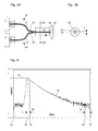
- FIG. 4 shows a typical course over time of the fluorescence intensity 35 measured on an ensemble of fluorophore molecules using the known, time correlated single photon counting (TCSPC - Time Correlated Single Photon Counting).
- TCSPC time correlated single photon counting
- the figure that is important for automatic adjustment is shown highest measuring point 31, which marks the maximum of the counted single photons.
- the characteristic time stamps 32 start of the measured time
- 33 time of maximum measurement
- 34 starting point for curve fitting the fluorescence intensity 35
- 36 end point for fitting the curve of the Fluorescence intensity 35
- 37 end of the measured time
Landscapes
- Health & Medical Sciences (AREA)
- Nuclear Medicine, Radiotherapy & Molecular Imaging (AREA)
- Physics & Mathematics (AREA)
- Life Sciences & Earth Sciences (AREA)
- Chemical & Material Sciences (AREA)
- Analytical Chemistry (AREA)
- Biochemistry (AREA)
- General Health & Medical Sciences (AREA)
- General Physics & Mathematics (AREA)
- Immunology (AREA)
- Pathology (AREA)
- Investigating, Analyzing Materials By Fluorescence Or Luminescence (AREA)
Abstract
Description
- das Floureszenz-Lebensdauersignal der Probe im Nanosekundenbereich ermöglicht - ausgehend von einer Vielzahl von Molekülen - die Anordnung und Auswertung von biochemischen Testreihen in Mikroplatten;
- das Fluoreszenzlebensdauer-Signal aus einer Zeitabschnittsmessung kann zum Unterscheiden des wirklichen Label Signals von der Eigenfluoreszenz der zu untersuchenden Verbindungen verwendet werden;
- sogar bei Anwesenheit von stark fluoreszierenden Verbindungen kann die Label-Fluoreszenz auf einfache Art von der Verbindungsfluoreszenz unterschieden werden;
- weil das Fluoreszenzlebensdauer-Signal ausschliesslich von einer Veränderung der physiko-chemischen Mikroumgebung der Probe abhängt, beeinflussen Artefakte, wie Streuung, der "Inner Filter Effekt", Unterschiede in Volumen und Meniskus, das Messsignal nicht.
- Fig. 1A
- den Grundriss einer Vorrichtung zum Messen der Lebensdauer der Fluoreszenz von Fluorophoren in Proben, gemäss einer ersten Ausführungsform;
- Fig. 1B
- die Frontansicht der Vorrichtung von Fig. 1A;
- Fig. 2A
- eine dreidimensionale Darstellung eines erfindungsgemässen Spiegelschiebers, gemäss einer ersten Ausführungsform;
- Fig. 2B
- eine weitere, dreidimensionale Darstellung des Spiegelschiebers von Fig. 2A;
- Fig. 3A
- den Grundriss einer ersten erfindungsgemässen Anordnung einer Faseroptik zum Ankoppeln von zwei Lasern an einer Anschlussstelle vor einer Sammellinse;
- Fig. 3B
- die Frontansicht der Anordnung von Fig. 3A, von der Sammellinse aus betrachtet;
- Fig. 4
- einen typischen zeitlichen Verlauf der Fluoreszenzintensität gemessen an einem Ensemble von Fluorophoren.
Das Abrastern oder "Scannen" aller Wells einer Mikroplatte 6 wird durch die beiden Doppelpfeile X und Y symbolisiert. Dieses Bewegen des eine Mikroplatte 6 tragenden Probentisches 5 erfolgt bevorzugt über eine computergesteuerte Automatik. Vorzugsweise ist auch der Arbeitsabstand zwischen Einstrahl- bzw. Emissionsoptik 3,7 und Mikroplatte 6 automatisch einstellbar. Im hier gezeigten Ausführungsbeispiel wird dieser Arbeitsabstand durch Verändern der Z-Position des Probentisches 5 eingestellt (siehe Doppelpfeil Z in Fig. 1B).

- n =
- 1(2) für mono(bi) exponentielle Anpassung
- t =
- Zeitabstand vom Nullpunkt
- a =
- Amplitude
- τ =
- Lebensdauer
- BG =
- Hintergrund
- y =
- errechneter, eine Probe charakterisierender Wert
Claims (19)
- Vorrichtung (1) zum Messen der Lebensdauer der Fluoreszenz von Fluorophoren in Proben, wobei die Vorrichtung zumindest eine Lichtquelle (2) zum Anregen der Fluoreszenz der Fluorophoren, eine Einstrahloptik (3) zum Lenken des Anregungslichts (4) auf diese Proben, einen Probentisch (5) zum Platzieren einer Proben enthaltenden Mikroplatte (6) bei der Einstrahloptik (3), eine Emissionsoptik (7) zum Lenken des Fluoreszenzlichtes (8) von den Proben auf einen Detektor (9) und zumindest einen Detektor (9) mit Auswertungselektronik umfasst, dadurch gekennzeichnet, dass die Einstrahloptik (3) der Vorrichtung (1) einen Strahlteiler (10) mit mindestens zwei Spiegeln (11) umfasst, welche einen Teil des Lichts (4) aus der zumindest einen Lichtquelle (2), das immer mit gleicher Leistung und gleicher Pulsform entlang einer ersten optischen Achse (12) in diesen Strahlteiler (10) eintritt, in Richtung einer Probe ablenken und einen Teil dieses Lichts auf den jeweils dahinter liegenden Spiegel (11) passieren lassen.
- Vorrichtung (1) nach Anspruch 1, dadurch gekennzeichnet, dass der Strahlteiler (10) als entlang dieser ersten optischen Achse (12) verschiebbarer Spiegelschlitten (13) ausgebildet ist und das Licht (4) aus der ersten Lichtquelle (2) um 90° in Richtung einer Probe ablenkt.
- Vorrichtung (1) nach Anspruch 1 oder 2, dadurch gekennzeichnet, dass die Spiegel (11) des Strahlteilers (10) jeweils 75% des auftreffenden Lichtes (4) reflektieren und 25% dieses Lichtes auf den jeweils dahinter liegenden Spiegel (11) passieren lassen.
- Vorrichtung (1) nach einem der vorhergehenden Ansprüche, welche zudem eine weitere Lichtquelle (18) umfasst, dadurch gekennzeichnet, dass der Strahlteiler (10) aus der Vorrichtung (1) herausnehmbar ausgebildet und durch ein Filterelement (19) ersetzbar ist, wobei das Filterelement (19) zumindest einen Filter (21) umfasst, welcher einen Teil des Lichts der Lichtquelle (18) in Richtung der Probe passieren lässt.
- Vorrichtung (1) nach Anspruch 4, dadurch gekennzeichnet, dass das Filterelement (19) als entlang dieser ersten optischen Achse (12) verschiebbarer Filterschlitten (20) ausgebildet ist, wobei der Bandpass der Filter (21) gleich oder unterschiedlich ist.
- Vorrichtung (1) nach zumindest einem der Ansprüche 2 bis 5, dadurch gekennzeichnet, dass der Spiegelschlitten (13) oder Filterschlitten (20) mit einem Antrieb automatisch in die für eine bestimmte Probe richtige Position verfahrbar ausgebildet ist.
- Vorrichtung (1) nach einem oder mehreren der vorhergehenden Ansprüche, wobei die Vorrichtung (1) zwei Lichtquellen (2) in Form von Lasern umfasst, dadurch gekennzeichnet, dass die beiden Laser an einen ersten Lichtleiter (25) bzw. zweiten Lichtleiter (25') gekoppelt sind und die beiden Lichtleiter (25,25') das Licht der beiden Laser an einer Anschlussstelle in eine Sammellinse (22) einspeisen, mit welcher die beiden dadurch definierten Fokuspunkte in einem bestimmten Well einer Mikroplatte (6) positionierbar sind.
- Vorrichtung (1) nach Anspruch 7, dadurch gekennzeichnet, dass bei der Anschlussstelle (22) im Bereich des Endes (29) des ersten und zweiten Lichtleiters (25,25') die Ummantelung (27,27') dieser Lichtleiter entfernt und durch eine gemeinsame Ummantelung (30) ersetzt ist, so dass die optischen Achsen (23,23') der beiden Lichtleiter (25,25') in einem minimalen Abstand (A) zueinander liegen.
- Vorrichtung (1) nach Anspruch 8, dadurch gekennzeichnet, dass der minimale Abstand (A) 125 µm beträgt.
- Vorrichtung nach einem oder mehreren der vorhergehenden Ansprüche, dadurch gekennzeichnet, dass die Vorrichtung einen Prozessor zur Steuerung der Vorrichtung (1) und zur automatischen Auswertung der Messdaten der Detektoren (9,9',9") sowie einen Antrieb des Probentisches (5) zur automatischen Positionierung der Wells einer Mikroplatte (6) bei Einstrahloptik (3) und Emissionsoptik (7) umfasst.
- Verfahren zum Messen der Lebensdauer der Fluoreszenz von Fluorophoren in Proben in einer Vorrichtung (1), wobei die Vorrichtung zumindest eine Lichtquelle (2) zum Anregen der Fluoreszenz der Fluorophoren, eine Einstrahloptik (3) zum Lenken des Anregungslichts (4) auf diese Proben, einen Probentisch (5) zum Platzieren einer Proben enthaltenden Mikroplatte (6) bei der Einstrahloptik (3), eine Emissionsoptik (7) zum Lenken des Fluoreszenzlichtes von den Proben auf einen Detektor und zumindest einen Detektor mit Auswertungselektronik umfasst, dadurch gekennzeichnet, dass das Licht aus der zumindest einen Lichtquelle (2) immer mit gleicher Leistung und gleicher Pulsform entlang einer ersten optischen Achse (12) in einen Strahlteiler (10) eingespeist wird, wobei der Strahlteiler (10) mindestens zwei Spiegel (11) umfasst, mit welchen ein Teil des Lichts (4) aus der zumindest einen Lichtquelle (2), in Richtung einer Probe abgelenkt und ein Teil dieses Lichts (4) auf den jeweils dahinter liegenden Spiegel (11) durchgelassen wird.
- Verfahren nach Anspruch 11, dadurch gekennzeichnet, dass der Strahlteiler (10) als entlang dieser ersten optischen Achse (12) verschiebbarer Spiegelschlitten (13) ausgebildet ist, wobei die Spiegel (11) des Strahlteilers (10) jeweils 75% des auftreffenden Lichtes um 90° in Richtung einer Probe reflektieren und 25% dieses Lichtes auf den jeweils dahinter liegenden Spiegel (11) passieren lassen.
- Verfahren nach einem der Ansprüche 11 oder 12, bei dem eine Vorrichtung (1) verwendet wird, welche zudem eine weitere Lichtquelle (18) umfasst, dadurch gekennzeichnet, dass der Strahlteiler (10) aus der Vorrichtung (1) herausgenommen und durch ein Filterelement (19) ersetzt wird, wobei das Filterelement (19) als entlang dieser ersten optischen Achse (12) verschiebbarer Filterschlitten (20) mit einem oder mehreren Filtern (21) - welche einen Teil des Lichts der weiteren Lichtquelle (18) in Richtung der Probe passieren lassen - ausgebildet ist.
- Verfahren nach Anspruch 12 oder 13, dadurch gekennzeichnet, dass der Spiegelschlitten (13) bzw. der Filterschlitten (20) mit einem Antrieb automatisch in die für eine bestimmte Probe richtige Position verfahren wird.
- Verfahren nach einem der Ansprüche 11 bis 14, wobei eine Vorrichtung (1) verwendet wird, die zwei Lichtquellen (2) in Form von Lasern umfasst, dadurch gekennzeichnet, dass die beiden Laser an einen ersten Lichtleiter (25) bzw. zweiten Lichtleiter (25') gekoppelt sind und die beiden Lichtleiter (25,25') das Licht der beiden Laser an einer Anschlussstelle in eine Sammellinse (22) einspeisen, welche die beiden dadurch definierten Fokuspunkte in einem bestimmten Well einer Mikroplatte (6) positioniert.
- Verfahren nach einem oder mehreren der vorhergehenden Ansprüche 11 bis 15, dadurch gekennzeichnet, dass es folgende Arbeitsschritte umfasst:1) Durchführen einer Referenzmessung ohne Anwesenheit einer Probe zum Bestimmen der Gerätekonstante;2) Ermitteln der Randbedingungen für die Angleichungsparameter ausgehend von der Referenzmessung:a) Bestimmen des Zeitpunktes (33) an dem das Maximum (31) auftritt;b) Bestimmen des Zeitpunktes (36), indem von dem Ende des Zeitfensters (36) eine konstantes Zeitintervall (39) subtrahiert wird;3) Messen der Proben in den Wells einer Mikroplatte.
- Verfahren nach Anspruch 16, dadurch gekennzeichnet, dass beim Messen der Proben in den Wells einer Mikroplatte (6) ein Anpassen der Probendaten ausgeführt wird, welches folgende Schritte umfasst:a) bi-exponentielle Voranpassung unter Verwendung der Randbedingungen aus 2), das Ergebnis sind zwei Lebensdauern;b1) Falls die erste Lebenszeit kurz ist und die dazugehörende erste Amplitude einen signifikanten Anteil der Gesamtamplitude darstellt, wird die Anpassung ausgehend vom Zeitpunkt (33) zuzüglich eines kurzen Zeitintervalls (38) gestartet;b2) Falls die Bedingungen von b1) nicht erfüllt sind, wird die Anpassung ausgehend vom Zeitpunkt (33) zuzüglich eines langen Zeitintervalls gestartet;c1) Falls die zweite Lebenszeit viel länger ist als die erste Lebenszeit, wird eine bi-exponentielle Anpassung ausgeführt, wobei die beiden Lebensdauern ermittelt werden;c2) Falls die Bedingungen von c1) nicht erfüllt sind, wird eine monoexponentielle Anpassung ausgeführt, wobei die einzelne Lebenszeit resultiert.
- Computerprogrammprodukt zur Steuerung der Vorrichtung (1) und zur automatischen Auswertung der Messdaten, dadurch gekennzeichnet, dass das in einem Computer aktivierte Computerprogrammprodukt einen Prozessor befähigt, mit der Vorrichtung (1) - gemäss zumindest einem der Ansprüche 1 bis 10 - zumindest ein Well einer Mikroplatte (6) anzusteuern, die Probe im Well mit Anregungslicht (4) zu aktivieren, die Lebensdauer der von der Probe ausgesendeten Fluoreszenz (8) zu messen und der Probe eine diese charakterisierende Kennzahl zuzuordnen.
- Computerprogrammprodukt zur Steuerung der Vorrichtung (1) und zur automatischen Auswertung der Messdaten, dadurch gekennzeichnet, dass das in einem Computer aktivierte Computerprogrammprodukt einen Prozessor befähigt, mit dem Verfahren gemäss zumindest einem der Ansprüche 11 bis 17 zumindest ein Well einer Mikroplatte (6) anzusteuern, die Probe im Well mit einem Anregungslicht (4) zu aktivieren, die Lebensdauer der von der Probe ausgesendeten Fluoreszenz (8) zu messen und der Probe eine diese charakterisierende Kennzahl zuzuordnen.
Applications Claiming Priority (2)
| Application Number | Priority Date | Filing Date | Title |
|---|---|---|---|
| CH13392002 | 2002-07-31 | ||
| CH13392002 | 2002-07-31 |
Publications (1)
| Publication Number | Publication Date |
|---|---|
| EP1387162A1 true EP1387162A1 (de) | 2004-02-04 |
Family
ID=4565393
Family Applications (1)
| Application Number | Title | Priority Date | Filing Date |
|---|---|---|---|
| EP03016383A Withdrawn EP1387162A1 (de) | 2002-07-31 | 2003-07-19 | Vorrichtung und Verfahren zum Messen der Lebensdauer der Fluoreszenz von Fluorophoren in Proben |
Country Status (2)
| Country | Link |
|---|---|
| EP (1) | EP1387162A1 (de) |
| DE (1) | DE20214868U1 (de) |
Cited By (2)
| Publication number | Priority date | Publication date | Assignee | Title |
|---|---|---|---|---|
| US7577064B2 (en) | 2005-07-11 | 2009-08-18 | Tecan Trading Ag | Microplate reader with intelligent filter slide |
| CN119715477A (zh) * | 2024-12-12 | 2025-03-28 | 北京理工大学 | 一种基于米散射与荧光发射双通道信号的荧光寿命特征值提取方法和系统 |
Families Citing this family (3)
| Publication number | Priority date | Publication date | Assignee | Title |
|---|---|---|---|---|
| DE102008045886A1 (de) * | 2008-09-03 | 2010-03-04 | Friedrich-Schiller-Universität Jena | Verfahren zur exakten Bestimmung der Fluoreszenz in einem Schichtsystem, beispielsweise dem Auge |
| DE102021107759B4 (de) | 2020-12-22 | 2024-01-18 | PicoQuant Innovations GmbH | Verfahren zum Ermitteln von Lumineszenzlebensdauern einer lumineszenten Probe |
| DE102024133072A1 (de) * | 2024-11-12 | 2026-05-13 | Bmg Labtech Gmbh | Verfahren zur Bestimmung von Messeinstellungen von spektralen Parametern für chemische und/oder biologische Proben in einer Mikroplatte, Verfahren zur Messung von Proben und Mikroplatten-Messsystem |
Citations (7)
| Publication number | Priority date | Publication date | Assignee | Title |
|---|---|---|---|---|
| GB2209422A (en) * | 1987-09-03 | 1989-05-10 | Emi Plc Thorn | Displays |
| US5542012A (en) * | 1993-07-30 | 1996-07-30 | Molecular Dynamics | Multi-functional photometer with movable linkage for routing optical fibers |
| DE19707226A1 (de) * | 1997-02-24 | 1998-08-27 | Bodenseewerk Perkin Elmer Co | Lichtabtastvorrichtung |
| WO1999023466A2 (en) * | 1997-10-31 | 1999-05-14 | Ljl Biosystems, Inc. | Apparatus and methods for measuring fluorescence polarization |
| DE29918300U1 (de) * | 1998-10-23 | 2000-07-13 | Tecan Austria GmbH, Grödig | Meßkopf |
| DE19914279C1 (de) * | 1999-03-25 | 2000-09-07 | Jena Optronik Gmbh | Anordnung zum optischen Auslesen der Information von einem matrixförmigen Substrat mit einer Vielzahl von Einzelproben |
| US6187267B1 (en) * | 1997-07-16 | 2001-02-13 | Ljl Biosystems, Inc. | Chemiluminescence detection device |
-
2002
- 2002-09-26 DE DE20214868U patent/DE20214868U1/de not_active Expired - Lifetime
-
2003
- 2003-07-19 EP EP03016383A patent/EP1387162A1/de not_active Withdrawn
Patent Citations (7)
| Publication number | Priority date | Publication date | Assignee | Title |
|---|---|---|---|---|
| GB2209422A (en) * | 1987-09-03 | 1989-05-10 | Emi Plc Thorn | Displays |
| US5542012A (en) * | 1993-07-30 | 1996-07-30 | Molecular Dynamics | Multi-functional photometer with movable linkage for routing optical fibers |
| DE19707226A1 (de) * | 1997-02-24 | 1998-08-27 | Bodenseewerk Perkin Elmer Co | Lichtabtastvorrichtung |
| US6187267B1 (en) * | 1997-07-16 | 2001-02-13 | Ljl Biosystems, Inc. | Chemiluminescence detection device |
| WO1999023466A2 (en) * | 1997-10-31 | 1999-05-14 | Ljl Biosystems, Inc. | Apparatus and methods for measuring fluorescence polarization |
| DE29918300U1 (de) * | 1998-10-23 | 2000-07-13 | Tecan Austria GmbH, Grödig | Meßkopf |
| DE19914279C1 (de) * | 1999-03-25 | 2000-09-07 | Jena Optronik Gmbh | Anordnung zum optischen Auslesen der Information von einem matrixförmigen Substrat mit einer Vielzahl von Einzelproben |
Cited By (2)
| Publication number | Priority date | Publication date | Assignee | Title |
|---|---|---|---|---|
| US7577064B2 (en) | 2005-07-11 | 2009-08-18 | Tecan Trading Ag | Microplate reader with intelligent filter slide |
| CN119715477A (zh) * | 2024-12-12 | 2025-03-28 | 北京理工大学 | 一种基于米散射与荧光发射双通道信号的荧光寿命特征值提取方法和系统 |
Also Published As
| Publication number | Publication date |
|---|---|
| DE20214868U1 (de) | 2003-03-13 |
Similar Documents
| Publication | Publication Date | Title |
|---|---|---|
| DE19653413C2 (de) | Rastermikroskop, bei dem eine Probe in mehreren Probenpunkten gleichzeitig optisch angeregt wird | |
| DE69530323T2 (de) | Verfahren und vorrichtung zur eichung eines optischen abtasters | |
| DE69937126T2 (de) | Detektor und Siebvorrichtung für Ionenkanäle | |
| EP2446314B1 (de) | Verfahren zum auswerten von fluoreszenzereignissen in einem mikroskopbild | |
| EP2684028B1 (de) | Vorrichtung für die analyse einer kleinen flüssigkeitsmenge | |
| DE19846928A1 (de) | Abbildungssystem mit einem Zylinderlinsenarray | |
| EP2072998A2 (de) | Vorrichtung zur wahlweisen Messung von insbesondere Lumineszenz und/oder Fluoreszenzstrahlung | |
| DE2755320A1 (de) | Radiometrisches abtastgeraet | |
| EP1511989B1 (de) | Fluoreszenzmesssystem | |
| EP1743162B1 (de) | Vorrichtung für die analyse oder absorptionsmessung an einer kleinen menge eines flüssigen mediums mit hilfe von licht | |
| DE60210878T2 (de) | Fortschrittliches System zur optischen Messung von Proben | |
| EP1279946B1 (de) | Vorrichtung zur wahlweisen Messung von Lumineszenz- und/oder Fluoreszenzstrahlung | |
| DE102008057115B4 (de) | Verfahren zur quantitativen Bestimmung der Konzentration von Fluorophoren einer Substanz in einer Probe und Vorrichtung zu seiner Durchführung | |
| DE10121064A1 (de) | Vorrichtung und Verfahren zur optischen Messung von chemischen und/oder biologischen Proben | |
| WO1998023944A1 (de) | Fluoreszenzkorrelationsspektroskopiemodul für ein mikroskop | |
| DE60205406T2 (de) | Optisches zweiwellenlängen-fluoreszenzanalysegerät | |
| DE19936999C2 (de) | Anordnung zum Erfassen der Fluoreszenzstrahlung von matrixförmigen Probenträgern | |
| DE60130452T2 (de) | Referenzvorrichtung zur Evaluierung der Funktion eines konfokalen Laserscanmikroskops, sowie Verfahren und System zur Durchführung der Evaluierung | |
| DE10303404A1 (de) | Verfahren zur Detektion von Fluoreszenzlicht | |
| EP3614130B1 (de) | Vorrichtung zur ermittlung optischer eigenschaften von proben | |
| DE20214868U1 (de) | Vorrichtung zum Messen der Lebensdauer der Fluoreszenz von Fluorophoren in Proben | |
| CH698317B1 (de) | Mikroplattenreader mit intelligentem Filterschieber. | |
| EP3649501A1 (de) | Verfahren zum untersuchen einer flüssigkeit, die wenigstens eine zelle und/oder wenigstens ein partikel enthält | |
| DE10042605A1 (de) | Bildinformationslesevorrichtung mit Mitteln zum Gleichmäßig-Halten des Pegels einer zu erfassenden Lichtmenge | |
| EP1523667B1 (de) | Dunkelfeld-abbildungsvorrichtung zur ortsaufgelösten dunkelfeldabbildung einer probe und untersuchungsverfahren |
Legal Events
| Date | Code | Title | Description |
|---|---|---|---|
| PUAI | Public reference made under article 153(3) epc to a published international application that has entered the european phase |
Free format text: ORIGINAL CODE: 0009012 |
|
| AK | Designated contracting states |
Kind code of ref document: A1 Designated state(s): AT BE BG CH CY CZ DE DK EE ES FI FR GB GR HU IE IT LI LU MC NL PT RO SE SI SK TR |
|
| AX | Request for extension of the european patent |
Extension state: AL LT LV MK |
|
| 17P | Request for examination filed |
Effective date: 20040519 |
|
| RIN1 | Information on inventor provided before grant (corrected) |
Inventor name: AISTLEITNER, HERWIG Inventor name: POPP, DIETER, DR. Inventor name: DOERING, KLAUS, DR. |
|
| AKX | Designation fees paid |
Designated state(s): CH DE FI FR GB LI |
|
| STAA | Information on the status of an ep patent application or granted ep patent |
Free format text: STATUS: THE APPLICATION IS DEEMED TO BE WITHDRAWN |
|
| 18D | Application deemed to be withdrawn |
Effective date: 20061010 |