EP1386839A1 - Verfahren und Maschine für integrierte Formung zum Herstellen von nichtentformbaren Bechern - Google Patents
Verfahren und Maschine für integrierte Formung zum Herstellen von nichtentformbaren Bechern Download PDFInfo
- Publication number
- EP1386839A1 EP1386839A1 EP03291460A EP03291460A EP1386839A1 EP 1386839 A1 EP1386839 A1 EP 1386839A1 EP 03291460 A EP03291460 A EP 03291460A EP 03291460 A EP03291460 A EP 03291460A EP 1386839 A1 EP1386839 A1 EP 1386839A1
- Authority
- EP
- European Patent Office
- Prior art keywords
- machine
- sections
- pots
- cutting
- sheet
- Prior art date
- Legal status (The legal status is an assumption and is not a legal conclusion. Google has not performed a legal analysis and makes no representation as to the accuracy of the status listed.)
- Granted
Links
Images


Classifications
-
- B—PERFORMING OPERATIONS; TRANSPORTING
- B21—MECHANICAL METAL-WORKING WITHOUT ESSENTIALLY REMOVING MATERIAL; PUNCHING METAL
- B21D—WORKING OR PROCESSING OF SHEET METAL OR METAL TUBES, RODS OR PROFILES WITHOUT ESSENTIALLY REMOVING MATERIAL; PUNCHING METAL
- B21D51/00—Making hollow objects
- B21D51/16—Making hollow objects characterised by the use of the objects
-
- B—PERFORMING OPERATIONS; TRANSPORTING
- B29—WORKING OF PLASTICS; WORKING OF SUBSTANCES IN A PLASTIC STATE IN GENERAL
- B29C—SHAPING OR JOINING OF PLASTICS; SHAPING OF MATERIAL IN A PLASTIC STATE, NOT OTHERWISE PROVIDED FOR; AFTER-TREATMENT OF THE SHAPED PRODUCTS, e.g. REPAIRING
- B29C51/00—Shaping by thermoforming, i.e. shaping sheets or sheet like preforms after heating, e.g. shaping sheets in matched moulds or by deep-drawing; Apparatus therefor
- B29C51/26—Component parts, details or accessories; Auxiliary operations
- B29C51/261—Handling means, e.g. transfer means, feeding means
-
- B—PERFORMING OPERATIONS; TRANSPORTING
- B65—CONVEYING; PACKING; STORING; HANDLING THIN OR FILAMENTARY MATERIAL
- B65B—MACHINES, APPARATUS OR DEVICES FOR, OR METHODS OF, PACKAGING ARTICLES OR MATERIALS; UNPACKING
- B65B47/00—Apparatus or devices for forming pockets or receptacles in or from sheets, blanks, or webs, comprising essentially a die into which the material is pressed or a folding die through which the material is moved
- B65B47/02—Apparatus or devices for forming pockets or receptacles in or from sheets, blanks, or webs, comprising essentially a die into which the material is pressed or a folding die through which the material is moved with means for heating the material prior to forming
-
- B—PERFORMING OPERATIONS; TRANSPORTING
- B65—CONVEYING; PACKING; STORING; HANDLING THIN OR FILAMENTARY MATERIAL
- B65B—MACHINES, APPARATUS OR DEVICES FOR, OR METHODS OF, PACKAGING ARTICLES OR MATERIALS; UNPACKING
- B65B9/00—Enclosing successive articles, or quantities of material, e.g. liquids or semiliquids, in flat, folded, or tubular webs of flexible sheet material; Subdividing filled flexible tubes to form packages
- B65B9/02—Enclosing successive articles, or quantities of material between opposed webs
- B65B9/04—Enclosing successive articles, or quantities of material between opposed webs one or both webs being formed with pockets for the reception of the articles, or of the quantities of material
-
- B—PERFORMING OPERATIONS; TRANSPORTING
- B29—WORKING OF PLASTICS; WORKING OF SUBSTANCES IN A PLASTIC STATE IN GENERAL
- B29C—SHAPING OR JOINING OF PLASTICS; SHAPING OF MATERIAL IN A PLASTIC STATE, NOT OTHERWISE PROVIDED FOR; AFTER-TREATMENT OF THE SHAPED PRODUCTS, e.g. REPAIRING
- B29C2793/00—Shaping techniques involving a cutting or machining operation
- B29C2793/0081—Shaping techniques involving a cutting or machining operation before shaping
-
- B—PERFORMING OPERATIONS; TRANSPORTING
- B29—WORKING OF PLASTICS; WORKING OF SUBSTANCES IN A PLASTIC STATE IN GENERAL
- B29C—SHAPING OR JOINING OF PLASTICS; SHAPING OF MATERIAL IN A PLASTIC STATE, NOT OTHERWISE PROVIDED FOR; AFTER-TREATMENT OF THE SHAPED PRODUCTS, e.g. REPAIRING
- B29C2793/00—Shaping techniques involving a cutting or machining operation
- B29C2793/009—Shaping techniques involving a cutting or machining operation after shaping
-
- B—PERFORMING OPERATIONS; TRANSPORTING
- B29—WORKING OF PLASTICS; WORKING OF SUBSTANCES IN A PLASTIC STATE IN GENERAL
- B29C—SHAPING OR JOINING OF PLASTICS; SHAPING OF MATERIAL IN A PLASTIC STATE, NOT OTHERWISE PROVIDED FOR; AFTER-TREATMENT OF THE SHAPED PRODUCTS, e.g. REPAIRING
- B29C49/00—Blow-moulding, i.e. blowing a preform or parison to a desired shape within a mould; Apparatus therefor
- B29C49/42—Component parts, details or accessories; Auxiliary operations
- B29C49/4205—Handling means, e.g. transfer, loading or discharging means
- B29C49/42113—Means for manipulating the objects' position or orientation
- B29C49/42121—Changing the center-center distance
- B29C49/42122—Adapting to blow-mould cavity center-center distance
-
- B—PERFORMING OPERATIONS; TRANSPORTING
- B29—WORKING OF PLASTICS; WORKING OF SUBSTANCES IN A PLASTIC STATE IN GENERAL
- B29C—SHAPING OR JOINING OF PLASTICS; SHAPING OF MATERIAL IN A PLASTIC STATE, NOT OTHERWISE PROVIDED FOR; AFTER-TREATMENT OF THE SHAPED PRODUCTS, e.g. REPAIRING
- B29C51/00—Shaping by thermoforming, i.e. shaping sheets or sheet like preforms after heating, e.g. shaping sheets in matched moulds or by deep-drawing; Apparatus therefor
- B29C51/18—Thermoforming apparatus
-
- B—PERFORMING OPERATIONS; TRANSPORTING
- B29—WORKING OF PLASTICS; WORKING OF SUBSTANCES IN A PLASTIC STATE IN GENERAL
- B29L—INDEXING SCHEME ASSOCIATED WITH SUBCLASS B29C, RELATING TO PARTICULAR ARTICLES
- B29L2031/00—Other particular articles
- B29L2031/712—Containers; Packaging elements or accessories, Packages
- B29L2031/7132—Bowls, Cups, Glasses
Definitions
- the invention relates to a method of manufacturing pots which are not can be removed by integrated forming without significant loss of material, as well as machine for implementing such a method.
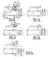
- a traditional technique uses integrated forming. It consists in providing the treatment, for example of a sheet thermoformable plastic 1, per cycle, per station and per group of pots.
- the sheet, wound around a reel 3, is unrolled longitudinally according to a continuous band and treated successively in different positions, equipped respectively with: means for heating the sheet 5, of molds forming 7 pots 8, dosing means 9 of the contents of the pots, of welding tools 11 of the operculum sheet 2 and of the final cut 13 per unit pot or per pack of pots.
- the treatment is continuous in longitudinal displacement thanks to an advance device 15.
- a receiving conveyor 16 is arranged at the output.
- the means of advance make it possible to pass at each end of the machine cycle, one or more transverse rows R of pots by step to another, in advancing a reel unwinding length corresponding to a pitch not say machine P1.
- the pitch machine P1 coincides in this case with the pitch of the P2 plastic sheet, not called material, which corresponds to the width of the area of the plastic sheet in the sense of advance, necessary for the treatment of different operations at different positions.
- pots can have more and more shapes more varied, with in particular significant undercuts. It follows they are not demoldable without opening the molds to the right of the post of forming and, possibly, that they are not disengageable in other tooling stations (welding or cutting), in particular each time a "neck" of the pot in the upper part is smaller than the "belly" of the pot.
- the molds or, possibly, the counter welding electrodes or dies, in closed conformation working position (for forming, welding or final cutting) with a 7h space are opened longitudinally while passing in position of transfer from one station to another with a footprint 7b; likewise welding and cutting tools, in conformation closed in position 11h and 13h respectively, are open in transfer position with longitudinal dimensions 11b and 13b.
- a sufficient longitudinal space E must be provided between R rows of pots.
- Another solution is to stretch the sheet periodically so that the E space obtained has a substantially greater material thickness low, which limits the amount of thermoformable material lost. This process is difficult to implement. In addition, it does not reduce losses in operculum material when it is traditionally in rolls longitudinals, or substantially increases the cost, of a cover material and in logistics, when it comes in the form of pre-cut lids.
- the present invention aims to completely eliminate losses of forming material and / or sealing between two rows, or a very much of these losses while retaining the benefits of integrated thermoforming. To do this, the sheet is cut in sections and to an appropriate positioning of these sections with respect to successive tools.
- the subject of the invention is a method of manufacture of non-moldable pots by integrated forming including successive processing tools of at least one sheet of material packaging, these tools having an opening of variable conformation in operation, the method of providing a preliminary cut of the packing sheet in sections according to a geometry appropriate to the processing tools, each section of the material being cut according to a step material set to be equal to very little greater than the width of material necessary for the forming or sealing process without taking into account opening of the tools, then successively positioning the sections for to advance them in a spaced way according to a not machine, not the machine being equal to very little greater than the largest tooling width in open transfer position.
- the forming can be carried out hot, from material of thermoforming, or cold.
- the invention applies both to forming and to lidding integrated pots by cutting the forming sheet and / or lidding according to a similar geometry.
- the material gain corresponds, in both cases, substantially to the material space between two rows of art jars previous, since the material is almost completely used according to the present including, possibly, below the "bellies” if the dimension of the "collar” of the pots allows it.
- the advantages of integrated forming are preserved, including a process for the management of continue one or more rows of pots per cycle on each of the stations of the machine, while removing all losses, or at least a large part of the losses, forming and sealing materials.
- the invention also relates to a setting machine process.
- This machine comprises cutting means in sections of at least one sheet of forming and / or sealing material powered from at least one coil, each leg having a width according to a treatment direction equal to a material pitch, means of regular removal of each section at a constant distance defining a space between the sections and transport these sections to different positions of treatment, as many sections as rows of pots to machine-made, these positions comprising, successively according to a treatment direction, at least one of the tools for forming, dosing, welding and final cutting pots, these tools can pass from a closed to open conformation in working position or transfer of a post to the other, the material pitch being set to be equal to very little higher than the width of material required for forming or sealing without taking into account account of the opening of the tools, and the machine pitch being equal to very little greater than the largest tooling width in open conformation.
- the non-demoldable pots 8a to 8f may have varied and complex shapes, and may be covered with a D: cylindrical decoration with a variable diameter (FIG. 2d) or with a troncocylindrical K neck (FIG. FIG. 2a) with screwed parts (FIG. 2f), cubic with possibly a hollow central part (FIG. 2e), or else spherical with a decoration D (FIG. 2b), spherical without decoration (FIG. 2g) or conical (FIG. ), or any other moldable form.
- the pots are closed by a lid O p welded to the flange C. It can thus be seen that screw threads can be produced, and that lateral decorations can also be deposited, the method according to the invention being compatible with decoration devices by streamer introduced into the mold before forming.
- thermoformable sheet 1 is fed from a reel 3 and cut into sections 4 by cutting means 6.
- the sections are driven by a transport chain 10 with pins 12, and then processed into successive posts by the various integrated thermoforming tools: heating boxes 5 of the sheet and the thermoforming molds 7 of the pots 8 (with molds, counter-molds and punches), the doser 9 of the contents of the pots, the sealing station equipped with welding electrodes 11 of the operculum foil 2, and the final cutting station equipped with cutting tools 13 pots per unit or pack.
- the treatment is at a continuous rate and allows you to end of treatment cycle, from one row of pots 8 to another.
- the integrated thermoforming tools treat pots to reason one row R per cycle and 6 pots per row.
- this machine comprises in particularly the cutting means 6 of the sheet 1 in rectangular sections 4, upstream of the treatment stations.
- the rectangle shape can be advantageously replaced by other forms, for example: parallelogram, trapezium, etc., to adapt to particular cases.
- the step P2 plastic is equal to P1 - E.
- treatment is performed at each of the posts by the molds 7 and the welding tools 11 and final cut 13 concerned to move from the work conformation, with a clutter minimum 7h, 11h and 13h, with the open conformation in transfer position of a station to another, with a respective maximum congestion 7b, 11b and 13b.
- the step P1 of the operating cycle of the machine and the cutting means 6 is barely greater than that of the openings of the means which has, in transfer position, the largest longitudinal dimension along the general direction F of the machine of transport, hereinafter maximum opening.
- the width P2 of each section of thermoformable material is 60 mm, corresponding substantially at the greatest width of the tools in the closed position of work, and the P1 machine pitch is set barely higher than the opening maximum processing tools (that of the release of the pots in the example), which is 100 mm, corresponding to the maximum width of tools in working position (60 mm) increased by two half-openings (twice 20 mm) of the half - tools of the maximum opening.
- the machine can be advantageously adapted to the treatment several rows of pots per operating cycle.
- the machine pitch P1 is equal to P2 + E, P2 being the plastic step or, already called, not material, and E the space between two sections of material. More generally, in the case of treatment with n rows of pots, the machine pitch is equal to n (P2 + E).
- the molds and treatment tools 7 ', 9', 11 'and 13' are doubled at each post.
- the displacement of the driven sections is then doubled and is, for example, of value barely greater than the opening maximum doubled 7'b of space tools 7'b, 9'b, 11'b and 13'b.
- the cutting means 6 of the sheet of material 1 are constituted by the guillotine 17, a shear or a wheel, associated with a anvil, one or more counter-blades, or a support matrix 19.
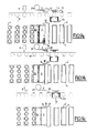
- the reference phase ( Figure 5a) represents the end of a cycle previous.
- the guillotine 17 is constituted of the matrix19, support of the sheet 1, and cutting blades 18, 21 driven by moving means perpendicular to the thermoforming sheet.
- Means for removing the cut sections are integral with the blade in the illustrated example, but can also be independent in other embodiments. In alternatively, other means of removal and positioning, such as suction carriages, ramps or slides, may be provided.
- the sheet is advanced (arrow H) by the rotational drive means 30 of the coil 3.
- the guillotine also has pre-cut blades 21 of the leaf, which act upstream of it. The function of these pre-cutting blades is making cuts in areas of the sheet for pecking, to avoid interference between the main blade and the sprocket chain.
- each section 4 is cut by vertical displacement (arrow F1) of the main blade 18 and pre-cutting blades 21 (arrow F2).
- the pre-cutting blades 21, controlled independently of the blade 18 in the example (but the blades can be single-commanded in other examples), are provided for forming two end cuts 22 in the sheet at the step preceding the step of section 4. These pre-cuts act on the entire thickness of the sheet to obtain a complete cut of the sheet in not cutting.
- the positioning of the sections 4 is achieved by combination with the pressing means of removal, in this embodiment. of the removal means can also serve as positioning means, such as clamps or mobile ramps.
- the picotage phase is more precisely illustrated in FIG. 5d.
- the press 23 drives (arrow F3, Figure 5d) the section 4 cut against the transport chain 10, and holes the section through the pins 12. To avoid interfere with the pins, the blade 18 and the press 23 are calibrated transversely so as not to interfere with the pins 12.
- FIGS. 6a to 6c show, in front view, the press 23 and the chain 10 provided with its pins 12, during three phases of operation.
- the section 4 presents itself with regard to the pins 12 of the chain 10.
- the press 23 is then actuated to push (arrows F3) the stretch on the pins 12 that pass through the plastic material and come to housed in clearance grooves 23a of the press 23 ( Figure 6b).
- the press 23 is actuated to go back to the initial level (arrow F4, FIG. 6c).
- the press means are separated from the blade and stroke cutting means is then limited to the necessities of the complete cut of the section.
- the pre-cut blades can then be deleted.
- Figures 7a to 7e show, in a similar way to FIGS. 5a to 5e, the five operating phases of cutting means lined for two thermoformable sheets of a machine adapted to the deposit two sections per machine step.
- two feed coils 3a are provided. and 3b, driven by means 30a, 30b for feeding two sheets of thermoformable material, respectively 1a and 1b, two cutting tools and deposit 17a and 17b, respectively comprising the support matrices 19a and 19b, the blades 18a and 18b, and the presses 23a and 23b.
- Pimples 12 of the sections, respectively 4a and 4b, are also provided.
- the sheets and the cutting means are superposed without contact and offset in the direction of movement F of a half-pitch machine P1 / 2 for respect the machine pitch P1 ( Figure 7e) of the example, very slightly greater than 200 mm (200 + ⁇ ).
- FIGS. 8a to 8f illustrate, in views schematic upper and lateral, six phases of operation of thermoformable sheet cutting means for a machine adapted to the cutting and deposition of two sections by machine step, but with coil single feed.
- FIG. 8a shows a reference state corresponding to the end of a previous cycle, which allowed the cutting of two sections 4a and 4b with a single cutting and removal tool, a guillotine 17 including the blade 18, the press 23 and the die 19.
- the leaf deformable In the preparation phase of the first cut, the leaf deformable is advanced according to the arrow F with a plastic pitch P2 of 60 mm ( Figure 8b). Then, in the cutting phase (FIG. 8c), the blade 18 and the press 23 are moved vertically in the low position (arrow V), the press descending at the level of the drive chains for removal. A section 4a is thus sliced and deposited.
- the sheet is advanced, by order of the means training 30 of the coil 3, a plastic pitch P2 increased by a half-step machine P1 / 2 (or P1 - E).
- the section 4b is then cut (FIG. 8f) and deposited by respective lowering of the blade 18 and the press 2 (arrow V). during the advance of the chain, so in masked time (0.5 s in the example), the blade-press assembly is then reassembled, the cutting tool moved to the rear (arrow H 'opposite the arrow H) of a half-pitch P1 / 2 and the coil plastic moves back a distance equal to the space E, to return to the state of reference of Figure 8a.
- the cutting tool is equipped with two blades for cutting two adjacent sections. These sections are positioned by sloping rails or ramps that carry each section of the "high" cutting position at the "low” picot sliding. For example, if the space E between sections is 40 mm, the sliding means position the first section of 20 mm in the direction the advance of the plastic sheet, while the second section slides 20 mm in the opposite direction.
- the section cutting tool is equipped with as many blades as sections to be cut, that is to say that rows of pots per step, and each section is brought into position then deposited on the means of advance (chain with pins, for example) by the use as many positioning trays (sucker trays, for example).
- the operculum material may advantageously, also cut into sections, according to a geometry identical or similar to that used in the cut into sections of the forming sheet by equivalent cutting means. Such a cut also allows to eliminate the losses of the operculum material between two rows of pots.
- Figures 9a to 9e illustrate, in schematic views superior and lateral, five phases of implementation of the operations of cutting and removal of the operculum material in sections 4 '.
- Reference Figure 9a shows a supply coil 25 operculum material 2 coupled to a cutting tool 17, similar to previous cutting tools.
- the coil 25 is disposed between the dosing pots 8 formed from sections 4, comprising the doser volumetric 9, and the welding station, comprising a welding press 11 composed of an upper cross member 11s for supporting the electrodes 14 and a lower cross member 11i support the counter electrode.
- the operculum sheet 2 is cut in section 4 'by lowering the blade 18, the section being deposited on the thermoforming material 1 by lowering the press 23 of the cutting tool 17.
- the lower cross-member 11i is raised (arrow V) in the same phase in order to prepare the welding sealing phase during the next phase.
- the positioning of the sections operculum is made by pre-sealing by welding means (no represented by points 27 of the sections 4 'of operculum material on the sections of plastic material 4.
- Welding points are located in the waste areas of the unused lid material, typically called the grid, in the case of a grid cut, or the stars, in the case of a cut without grille to round the corners of the flanges.
- This pre-welding serves to drive the sections of seal material properly positioned to the welding station pots.
- the sealing itself is initiated by closing the welding press by horizontal displacement (arrows H1 and H2) of the walls 11l of the lower cross member 11i and a lowering (arrow V ') of the upper rail 11s. Electrodes previously raised to high temperature (for example at 200 ° C.), result in the melting of a lacquer contained in the lid, or self-sealing materials, for example polyethylene on polyethylene.
- the final phase ( Figure 9e) consists of raising the blade of cut 18 and the press 23 (arrow V) of the cutting tool 17, and to open the solder press 11 by displacement of the top rail 11s (arrow V), walls 11l (arrows H '1 and H'2) and bottom rail 11i (arrow V ').
- the welding station then returned to the reference conformation (FIG. 9a).
- the material cutting system operculum may comprise as many coils as rows of pots to be treated, or a single coil for several rows with successive cutting (and positioning) or simultaneously (with feeding into position) as for the deformable material.
- the cutting and dispensing operations of operculum material are conducted laterally in accordance with the figures 10a to 10c as part of a treatment pots in rows of two.
- This variant is particularly suitable when the machine can handle simultaneously several rows of pots to increase its capacity.
- the welding station of the material operculum consists of a welding press 11 ', consisting of a upper cross 11 ', and a lower cross 11'i, forming a tool double.
- the supply reel 25 of the operculum sheet 2 is arranged so that its axis X'X is parallel to the direction of displacement F of the transport chain 10. The sheet is thus unrolled parallel to the rows R pots 8.
- a blade system 29 can split the sheet 2 longitudinally. The multiplication of this blade system allows more generally, to split the operculum leaf into as many sections as rows of pots to treat.
- the two streamers formed 2a and 2b are arranged above sections 4 of deformable material by advancing means side and cut by a cutting tool 17 blade 18 on a counterblade 33 to form sections of operculum 4 '.
- Separation guides trained by rollers T1 to T4 in the example shown, allow to separate the streamers after twisting.
- Figure 10b illustrates the placement of streamers operculum material 2a and 2b.
- the means sideways, in the form of rolls T5 and T6 push the streamers transversely (arrows T) in relation to the direction of advance pots to direct them to the forming sections.
- Means of guiding formed by slides 31 and 32 position the sections of opercle 4 'with regard to sections 4 of rows of corresponding pots
- the operculum streamers are cut into 4 'sections by the cutting tool 17 (FIG. 10c), the welding press 11 is closed to proceed to the welding of the sections of lid (arrows H'1, H'2, V and V ') and the dosing of the products is carried out at the dosing station 9.
- the streamers are welded directly on the sections 4.
- a return to conformation illustrated by the Figure 10a is performed.
- the final cut advantageously allows to obtain, particularly in the case of multiple row processing, single or packaged pots, as shown in Figures 11a to 11c.
- the cutting is performed by blade tools positioned to form pots 8 (FIG. 11a) packs 35 of 2 pots 8 (FIG. 11b) or packs 37 of 3 pots (Figure 11c) according to the illustrated examples.
- FIGS. 12a and 12b there is schematically illustrated the material gain obtained with the manufacturing process according to the invention for the manufacture of a pot 8g, the type of that illustrated in Figure 2g for example.
- P2 (aa) of the prior art
- just a section of material width equal to step P2 significantly less than P2 (aa), which corresponds to a gain of material G1 + G2 equal to the space E mentioned above.
- the pitch P2 of the plastic section may be adjusted, in certain cases, so as to be substantially equal to the width of the flange C, and therefore substantially less wide than the belly Ve pot 8g: we can then speak of negative losses, m 1 + m 2 , between the width of the section of plastic and that of the belly Ve, with respect to the width of the section in the case of Figure 12a.
- thermoforming is replaced by a system of deformation of the metal by mechanical punching with optional gas or liquid pressure.
Applications Claiming Priority (2)
| Application Number | Priority Date | Filing Date | Title |
|---|---|---|---|
| FR0209873 | 2002-08-02 | ||
| FR0209873A FR2843094B1 (fr) | 2002-08-02 | 2002-08-02 | Procede et machine de formage integre pour la fabrication de pots non demoulables sans perte notable de materiau. |
Publications (2)
| Publication Number | Publication Date |
|---|---|
| EP1386839A1 true EP1386839A1 (de) | 2004-02-04 |
| EP1386839B1 EP1386839B1 (de) | 2007-06-27 |
Family
ID=30011626
Family Applications (1)
| Application Number | Title | Priority Date | Filing Date |
|---|---|---|---|
| EP03291460A Expired - Lifetime EP1386839B1 (de) | 2002-08-02 | 2003-06-17 | Verfahren und Maschine für integrierte Formung zum Herstellen von nichtentformbaren Bechern |
Country Status (5)
| Country | Link |
|---|---|
| EP (1) | EP1386839B1 (de) |
| CN (1) | CN1480318B (de) |
| DE (1) | DE60314567T2 (de) |
| ES (1) | ES2289247T3 (de) |
| FR (1) | FR2843094B1 (de) |
Cited By (4)
| Publication number | Priority date | Publication date | Assignee | Title |
|---|---|---|---|---|
| WO2004106162A3 (en) * | 2003-05-30 | 2006-03-23 | Kourtoglou Sa | Plastic packaging container as well as a molding station, a packaging machine and a method of producing the packaging container |
| WO2011114043A2 (fr) | 2010-03-17 | 2011-09-22 | Erca Formseal | Procede et dispositif de fabrication de recipients par thermoformage |
| EP3326782A1 (de) * | 2016-11-28 | 2018-05-30 | Synerlink | Hinterschnittene töpfe, formen, formvorrichtungen und produktionslinien zum herstellen von hinterschnittenen töpfe |
| CN110421642A (zh) * | 2019-07-10 | 2019-11-08 | 杭州中亚机械股份有限公司 | 一种装饰条供应方法 |
Families Citing this family (1)
| Publication number | Priority date | Publication date | Assignee | Title |
|---|---|---|---|---|
| CN102795355A (zh) * | 2012-08-22 | 2012-11-28 | 大连巨峰包装制品有限公司 | 袋装物料的包装方法 |
Citations (4)
| Publication number | Priority date | Publication date | Assignee | Title |
|---|---|---|---|---|
| US4261949A (en) * | 1979-01-19 | 1981-04-14 | Emhart Industries, Inc. | Process for formation of molecularly oriented plastic bottles |
| FR2644425A1 (fr) * | 1989-03-17 | 1990-09-21 | Erca Holding | Dispositif de separation des recipients remplis dans une installation de conditionnement d'emballages a partir d'une bande thermoplastique |
| DE19627675A1 (de) * | 1996-07-10 | 1998-01-15 | Walter Lauermann | Tiefziehsystem zur Herstellung von Hohlkörpern, insbesondere Behältnissen |
| US6094890A (en) * | 1997-07-21 | 2000-08-01 | Erca S.A. | Thermoforming, filling, and capping receptacles |
Family Cites Families (1)
| Publication number | Priority date | Publication date | Assignee | Title |
|---|---|---|---|---|
| IT1268286B1 (it) * | 1994-09-14 | 1997-02-27 | Isap Omv Group Spa | Apparecchiatura di termoformatura di materiali termoformabili in nastro o lastra |
-
2002
- 2002-08-02 FR FR0209873A patent/FR2843094B1/fr not_active Expired - Fee Related
-
2003
- 2003-06-17 DE DE60314567T patent/DE60314567T2/de not_active Expired - Lifetime
- 2003-06-17 EP EP03291460A patent/EP1386839B1/de not_active Expired - Lifetime
- 2003-06-17 ES ES03291460T patent/ES2289247T3/es not_active Expired - Lifetime
- 2003-07-30 CN CN03153019.2A patent/CN1480318B/zh not_active Expired - Lifetime
Patent Citations (4)
| Publication number | Priority date | Publication date | Assignee | Title |
|---|---|---|---|---|
| US4261949A (en) * | 1979-01-19 | 1981-04-14 | Emhart Industries, Inc. | Process for formation of molecularly oriented plastic bottles |
| FR2644425A1 (fr) * | 1989-03-17 | 1990-09-21 | Erca Holding | Dispositif de separation des recipients remplis dans une installation de conditionnement d'emballages a partir d'une bande thermoplastique |
| DE19627675A1 (de) * | 1996-07-10 | 1998-01-15 | Walter Lauermann | Tiefziehsystem zur Herstellung von Hohlkörpern, insbesondere Behältnissen |
| US6094890A (en) * | 1997-07-21 | 2000-08-01 | Erca S.A. | Thermoforming, filling, and capping receptacles |
Cited By (8)
| Publication number | Priority date | Publication date | Assignee | Title |
|---|---|---|---|---|
| WO2004106162A3 (en) * | 2003-05-30 | 2006-03-23 | Kourtoglou Sa | Plastic packaging container as well as a molding station, a packaging machine and a method of producing the packaging container |
| WO2011114043A2 (fr) | 2010-03-17 | 2011-09-22 | Erca Formseal | Procede et dispositif de fabrication de recipients par thermoformage |
| WO2011114043A3 (fr) * | 2010-03-17 | 2011-12-29 | Erca Formseal | Procédé et dispositif de fabrication de récipients par thermoformage |
| US9694533B2 (en) | 2010-03-17 | 2017-07-04 | Erca | Method and device for manufacturing containers by thermoforming |
| EP3326782A1 (de) * | 2016-11-28 | 2018-05-30 | Synerlink | Hinterschnittene töpfe, formen, formvorrichtungen und produktionslinien zum herstellen von hinterschnittenen töpfe |
| FR3059306A1 (fr) * | 2016-11-28 | 2018-06-01 | Synerlink | Pots a contre-depouille, moules ouvrants, machines de formages et lignes de fabrication de pots a contre-depouille |
| CN110421642A (zh) * | 2019-07-10 | 2019-11-08 | 杭州中亚机械股份有限公司 | 一种装饰条供应方法 |
| CN110421642B (zh) * | 2019-07-10 | 2023-05-26 | 杭州中亚机械股份有限公司 | 一种装饰条供应方法 |
Also Published As
| Publication number | Publication date |
|---|---|
| CN1480318B (zh) | 2010-05-26 |
| FR2843094B1 (fr) | 2004-10-15 |
| DE60314567D1 (de) | 2007-08-09 |
| CN1480318A (zh) | 2004-03-10 |
| EP1386839B1 (de) | 2007-06-27 |
| DE60314567T2 (de) | 2008-02-28 |
| ES2289247T3 (es) | 2008-02-01 |
| FR2843094A1 (fr) | 2004-02-06 |
Similar Documents
| Publication | Publication Date | Title |
|---|---|---|
| FR2766123A1 (fr) | Installation et procede de fabrication de recipients par thermoformage | |
| FR2686827A1 (fr) | Procede et appareillage de thermoformage et d'extraction d'objets creux d'un fond a partir d'une bande de matiere thermoplastique. | |
| EP2956292B1 (de) | Verpackung von einer gruppe mit mindestens zwei kunststoffbehältern | |
| EP2914523B1 (de) | Halterungsvorrichtung für ein plattes, blattförmiges element, das sich in einer bearbeitungsmaschine dreht | |
| EP1312548B1 (de) | Vorrichtung zum Ausschneiden einer Reihe von Membranverschlüssen aus einer Bahn und zur Fixierung dieser auf einer Reihe von gefüllten Behältern | |
| EP2688805B1 (de) | Verfahren zum verpacken von produkten, insbesondere von schokolade oder dergleichen und anlage zur durchführung des verfahrens | |
| FR2528386A1 (fr) | Procede et installation de conditionnement d'un produit | |
| EP1386839B1 (de) | Verfahren und Maschine für integrierte Formung zum Herstellen von nichtentformbaren Bechern | |
| EP2117809B1 (de) | Vorrichtung und verfahren zum thermoformen von ziergefässen zum aufbringen von bodenetiketten auf thermogeformten gefässen | |
| FR2922806A1 (fr) | Procede et dispositif pour fabriquer en grande cadence des corps en matiere plastique dont la surface exterieure est munie d'une etiquette | |
| FR2784654A1 (fr) | Procede et dispositif de conditionnement de produits et barquettes de conditionnement correspondantes | |
| EP2547507B1 (de) | Verfahren und vorrichtung zur herstellung von behältern mittels thermoformen | |
| EP1690791B1 (de) | Verfahren und Vorrichtung zum Thermoformen von Behältern | |
| EP2582514A1 (de) | Werkzeughaltermodul zur herstellung von zumindest einem kartonausschnitt | |
| FR2623438A1 (fr) | Installation permettant la decoupe de flans elementaires, en carton notamment, destines a la realisation d'emballages | |
| FR2644425A1 (fr) | Dispositif de separation des recipients remplis dans une installation de conditionnement d'emballages a partir d'une bande thermoplastique | |
| FR2657295A1 (fr) | Installation pour la fabrication en ligne et a plat, d'emballages en matiere synthetique. | |
| EP0885805A1 (de) | Verfahren und Vorrichtung zum Thermoformen, Füllen und Verschliessen von Kunststoffbechern | |
| EP3797968B1 (de) | Vorrichtung zum thermoformen, folienverschliessen und schneiden von behähltern von unterschiedlichen grössen | |
| EP1414638B1 (de) | Verfahren und anlage zur wärmeformung von behältern unter begrenzung von materialverlusten | |
| EP0151364A2 (de) | Verpackungsstrasse für Produkte mit einem Film in einem aus einem flachen vorgeschnittenen Zuschnitt hergestellten Behälter | |
| EP3261817B1 (de) | Vorrichtung zum thermoformen von behältern mit translationalen formblöcken und verfahren | |
| FR2465576A1 (fr) | Dispositif pour le decoupage automatique de plaquettes a partir d'une bande continue | |
| EP0516556B1 (de) | Verfahren zum Thermoverformen und eventuell weiteren Verpacken von Behältern und Maschine dafür | |
| FR2611581A1 (fr) | Procede de fabrication d'outres en matiere synthetique, dispositif pour la mise en oeuvre de ce procede, et outre ainsi obtenue |
Legal Events
| Date | Code | Title | Description |
|---|---|---|---|
| PUAI | Public reference made under article 153(3) epc to a published international application that has entered the european phase |
Free format text: ORIGINAL CODE: 0009012 |
|
| AK | Designated contracting states |
Kind code of ref document: A1 Designated state(s): AT BE BG CH CY CZ DE DK EE ES FI FR GB GR HU IE IT LI LU MC NL PT RO SE SI SK TR |
|
| AX | Request for extension of the european patent |
Extension state: AL LT LV MK SI |
|
| 17P | Request for examination filed |
Effective date: 20040510 |
|
| AKX | Designation fees paid |
Designated state(s): DE ES FR GR IT |
|
| GRAP | Despatch of communication of intention to grant a patent |
Free format text: ORIGINAL CODE: EPIDOSNIGR1 |
|
| GRAS | Grant fee paid |
Free format text: ORIGINAL CODE: EPIDOSNIGR3 |
|
| GRAA | (expected) grant |
Free format text: ORIGINAL CODE: 0009210 |
|
| AK | Designated contracting states |
Kind code of ref document: B1 Designated state(s): DE ES FR GR IT |
|
| REF | Corresponds to: |
Ref document number: 60314567 Country of ref document: DE Date of ref document: 20070809 Kind code of ref document: P |
|
| REG | Reference to a national code |
Ref country code: GR Ref legal event code: EP Ref document number: 20070402820 Country of ref document: GR |
|
| RAP2 | Party data changed (patent owner data changed or rights of a patent transferred) |
Owner name: A.R.C.I.L. |
|
| REG | Reference to a national code |
Ref country code: ES Ref legal event code: FG2A Ref document number: 2289247 Country of ref document: ES Kind code of ref document: T3 |
|
| PLBE | No opposition filed within time limit |
Free format text: ORIGINAL CODE: 0009261 |
|
| STAA | Information on the status of an ep patent application or granted ep patent |
Free format text: STATUS: NO OPPOSITION FILED WITHIN TIME LIMIT |
|
| 26N | No opposition filed |
Effective date: 20080328 |
|
| PG25 | Lapsed in a contracting state [announced via postgrant information from national office to epo] |
Ref country code: IT Free format text: LAPSE BECAUSE OF NON-PAYMENT OF DUE FEES Effective date: 20080617 |
|
| REG | Reference to a national code |
Ref country code: FR Ref legal event code: PLFP Year of fee payment: 13 |
|
| REG | Reference to a national code |
Ref country code: FR Ref legal event code: PLFP Year of fee payment: 14 |
|
| REG | Reference to a national code |
Ref country code: FR Ref legal event code: PLFP Year of fee payment: 15 |
|
| REG | Reference to a national code |
Ref country code: FR Ref legal event code: CD Owner name: SYNERLINK, FR Effective date: 20180104 |
|
| REG | Reference to a national code |
Ref country code: DE Ref legal event code: R082 Ref document number: 60314567 Country of ref document: DE Representative=s name: MEISSNER BOLTE PATENTANWAELTE RECHTSANWAELTE P, DE Ref country code: DE Ref legal event code: R081 Ref document number: 60314567 Country of ref document: DE Owner name: SYNERLINK, FR Free format text: FORMER OWNER: A.R.C.I.L., PUISEUX, PONTOISE, FR |
|
| REG | Reference to a national code |
Ref country code: ES Ref legal event code: PC2A Owner name: SYNERLINK Effective date: 20180223 |
|
| REG | Reference to a national code |
Ref country code: FR Ref legal event code: PLFP Year of fee payment: 16 |
|
| PGFP | Annual fee paid to national office [announced via postgrant information from national office to epo] |
Ref country code: IT Payment date: 20220627 Year of fee payment: 20 Ref country code: DE Payment date: 20220620 Year of fee payment: 20 |
|
| PGFP | Annual fee paid to national office [announced via postgrant information from national office to epo] |
Ref country code: GR Payment date: 20220610 Year of fee payment: 20 |
|
| PGFP | Annual fee paid to national office [announced via postgrant information from national office to epo] |
Ref country code: FR Payment date: 20220601 Year of fee payment: 20 |
|
| PGFP | Annual fee paid to national office [announced via postgrant information from national office to epo] |
Ref country code: ES Payment date: 20220829 Year of fee payment: 20 |
|
| REG | Reference to a national code |
Ref country code: DE Ref legal event code: R071 Ref document number: 60314567 Country of ref document: DE |
|
| REG | Reference to a national code |
Ref country code: ES Ref legal event code: FD2A Effective date: 20230626 |
|
| PG25 | Lapsed in a contracting state [announced via postgrant information from national office to epo] |
Ref country code: ES Free format text: LAPSE BECAUSE OF EXPIRATION OF PROTECTION Effective date: 20230618 |