EP1386839A1 - Integrated forming method and machine for manufacturing non-demouldable cups - Google Patents
Integrated forming method and machine for manufacturing non-demouldable cups Download PDFInfo
- Publication number
- EP1386839A1 EP1386839A1 EP03291460A EP03291460A EP1386839A1 EP 1386839 A1 EP1386839 A1 EP 1386839A1 EP 03291460 A EP03291460 A EP 03291460A EP 03291460 A EP03291460 A EP 03291460A EP 1386839 A1 EP1386839 A1 EP 1386839A1
- Authority
- EP
- European Patent Office
- Prior art keywords
- machine
- sections
- pots
- cutting
- sheet
- Prior art date
- Legal status (The legal status is an assumption and is not a legal conclusion. Google has not performed a legal analysis and makes no representation as to the accuracy of the status listed.)
- Granted
Links
Images


Classifications
-
- B—PERFORMING OPERATIONS; TRANSPORTING
- B21—MECHANICAL METAL-WORKING WITHOUT ESSENTIALLY REMOVING MATERIAL; PUNCHING METAL
- B21D—WORKING OR PROCESSING OF SHEET METAL OR METAL TUBES, RODS OR PROFILES WITHOUT ESSENTIALLY REMOVING MATERIAL; PUNCHING METAL
- B21D51/00—Making hollow objects
- B21D51/16—Making hollow objects characterised by the use of the objects
-
- B—PERFORMING OPERATIONS; TRANSPORTING
- B29—WORKING OF PLASTICS; WORKING OF SUBSTANCES IN A PLASTIC STATE IN GENERAL
- B29C—SHAPING OR JOINING OF PLASTICS; SHAPING OF MATERIAL IN A PLASTIC STATE, NOT OTHERWISE PROVIDED FOR; AFTER-TREATMENT OF THE SHAPED PRODUCTS, e.g. REPAIRING
- B29C51/00—Shaping by thermoforming, i.e. shaping sheets or sheet like preforms after heating, e.g. shaping sheets in matched moulds or by deep-drawing; Apparatus therefor
- B29C51/26—Component parts, details or accessories; Auxiliary operations
- B29C51/261—Handling means, e.g. transfer means, feeding means
-
- B—PERFORMING OPERATIONS; TRANSPORTING
- B65—CONVEYING; PACKING; STORING; HANDLING THIN OR FILAMENTARY MATERIAL
- B65B—MACHINES, APPARATUS OR DEVICES FOR, OR METHODS OF, PACKAGING ARTICLES OR MATERIALS; UNPACKING
- B65B47/00—Apparatus or devices for forming pockets or receptacles in or from sheets, blanks, or webs, comprising essentially a die into which the material is pressed or a folding die through which the material is moved
- B65B47/02—Apparatus or devices for forming pockets or receptacles in or from sheets, blanks, or webs, comprising essentially a die into which the material is pressed or a folding die through which the material is moved with means for heating the material prior to forming
-
- B—PERFORMING OPERATIONS; TRANSPORTING
- B65—CONVEYING; PACKING; STORING; HANDLING THIN OR FILAMENTARY MATERIAL
- B65B—MACHINES, APPARATUS OR DEVICES FOR, OR METHODS OF, PACKAGING ARTICLES OR MATERIALS; UNPACKING
- B65B9/00—Enclosing successive articles, or quantities of material, e.g. liquids or semiliquids, in flat, folded, or tubular webs of flexible sheet material; Subdividing filled flexible tubes to form packages
- B65B9/02—Enclosing successive articles, or quantities of material between opposed webs
- B65B9/04—Enclosing successive articles, or quantities of material between opposed webs one or both webs being formed with pockets for the reception of the articles, or of the quantities of material
-
- B—PERFORMING OPERATIONS; TRANSPORTING
- B29—WORKING OF PLASTICS; WORKING OF SUBSTANCES IN A PLASTIC STATE IN GENERAL
- B29C—SHAPING OR JOINING OF PLASTICS; SHAPING OF MATERIAL IN A PLASTIC STATE, NOT OTHERWISE PROVIDED FOR; AFTER-TREATMENT OF THE SHAPED PRODUCTS, e.g. REPAIRING
- B29C2793/00—Shaping techniques involving a cutting or machining operation
- B29C2793/0081—Shaping techniques involving a cutting or machining operation before shaping
-
- B—PERFORMING OPERATIONS; TRANSPORTING
- B29—WORKING OF PLASTICS; WORKING OF SUBSTANCES IN A PLASTIC STATE IN GENERAL
- B29C—SHAPING OR JOINING OF PLASTICS; SHAPING OF MATERIAL IN A PLASTIC STATE, NOT OTHERWISE PROVIDED FOR; AFTER-TREATMENT OF THE SHAPED PRODUCTS, e.g. REPAIRING
- B29C2793/00—Shaping techniques involving a cutting or machining operation
- B29C2793/009—Shaping techniques involving a cutting or machining operation after shaping
-
- B—PERFORMING OPERATIONS; TRANSPORTING
- B29—WORKING OF PLASTICS; WORKING OF SUBSTANCES IN A PLASTIC STATE IN GENERAL
- B29C—SHAPING OR JOINING OF PLASTICS; SHAPING OF MATERIAL IN A PLASTIC STATE, NOT OTHERWISE PROVIDED FOR; AFTER-TREATMENT OF THE SHAPED PRODUCTS, e.g. REPAIRING
- B29C49/00—Blow-moulding, i.e. blowing a preform or parison to a desired shape within a mould; Apparatus therefor
- B29C49/42—Component parts, details or accessories; Auxiliary operations
- B29C49/4205—Handling means, e.g. transfer, loading or discharging means
- B29C49/42113—Means for manipulating the objects' position or orientation
- B29C49/42121—Changing the center-center distance
- B29C49/42122—Adapting to blow-mould cavity center-center distance
-
- B—PERFORMING OPERATIONS; TRANSPORTING
- B29—WORKING OF PLASTICS; WORKING OF SUBSTANCES IN A PLASTIC STATE IN GENERAL
- B29C—SHAPING OR JOINING OF PLASTICS; SHAPING OF MATERIAL IN A PLASTIC STATE, NOT OTHERWISE PROVIDED FOR; AFTER-TREATMENT OF THE SHAPED PRODUCTS, e.g. REPAIRING
- B29C51/00—Shaping by thermoforming, i.e. shaping sheets or sheet like preforms after heating, e.g. shaping sheets in matched moulds or by deep-drawing; Apparatus therefor
- B29C51/18—Thermoforming apparatus
-
- B—PERFORMING OPERATIONS; TRANSPORTING
- B29—WORKING OF PLASTICS; WORKING OF SUBSTANCES IN A PLASTIC STATE IN GENERAL
- B29L—INDEXING SCHEME ASSOCIATED WITH SUBCLASS B29C, RELATING TO PARTICULAR ARTICLES
- B29L2031/00—Other particular articles
- B29L2031/712—Containers; Packaging elements or accessories, Packages
- B29L2031/7132—Bowls, Cups, Glasses
Definitions
- the invention relates to a method of manufacturing pots which are not can be removed by integrated forming without significant loss of material, as well as machine for implementing such a method.
- a traditional technique uses integrated forming. It consists in providing the treatment, for example of a sheet thermoformable plastic 1, per cycle, per station and per group of pots.
- the sheet, wound around a reel 3, is unrolled longitudinally according to a continuous band and treated successively in different positions, equipped respectively with: means for heating the sheet 5, of molds forming 7 pots 8, dosing means 9 of the contents of the pots, of welding tools 11 of the operculum sheet 2 and of the final cut 13 per unit pot or per pack of pots.
- the treatment is continuous in longitudinal displacement thanks to an advance device 15.
- a receiving conveyor 16 is arranged at the output.
- the means of advance make it possible to pass at each end of the machine cycle, one or more transverse rows R of pots by step to another, in advancing a reel unwinding length corresponding to a pitch not say machine P1.
- the pitch machine P1 coincides in this case with the pitch of the P2 plastic sheet, not called material, which corresponds to the width of the area of the plastic sheet in the sense of advance, necessary for the treatment of different operations at different positions.
- pots can have more and more shapes more varied, with in particular significant undercuts. It follows they are not demoldable without opening the molds to the right of the post of forming and, possibly, that they are not disengageable in other tooling stations (welding or cutting), in particular each time a "neck" of the pot in the upper part is smaller than the "belly" of the pot.
- the molds or, possibly, the counter welding electrodes or dies, in closed conformation working position (for forming, welding or final cutting) with a 7h space are opened longitudinally while passing in position of transfer from one station to another with a footprint 7b; likewise welding and cutting tools, in conformation closed in position 11h and 13h respectively, are open in transfer position with longitudinal dimensions 11b and 13b.
- a sufficient longitudinal space E must be provided between R rows of pots.
- Another solution is to stretch the sheet periodically so that the E space obtained has a substantially greater material thickness low, which limits the amount of thermoformable material lost. This process is difficult to implement. In addition, it does not reduce losses in operculum material when it is traditionally in rolls longitudinals, or substantially increases the cost, of a cover material and in logistics, when it comes in the form of pre-cut lids.
- the present invention aims to completely eliminate losses of forming material and / or sealing between two rows, or a very much of these losses while retaining the benefits of integrated thermoforming. To do this, the sheet is cut in sections and to an appropriate positioning of these sections with respect to successive tools.
- the subject of the invention is a method of manufacture of non-moldable pots by integrated forming including successive processing tools of at least one sheet of material packaging, these tools having an opening of variable conformation in operation, the method of providing a preliminary cut of the packing sheet in sections according to a geometry appropriate to the processing tools, each section of the material being cut according to a step material set to be equal to very little greater than the width of material necessary for the forming or sealing process without taking into account opening of the tools, then successively positioning the sections for to advance them in a spaced way according to a not machine, not the machine being equal to very little greater than the largest tooling width in open transfer position.
- the forming can be carried out hot, from material of thermoforming, or cold.
- the invention applies both to forming and to lidding integrated pots by cutting the forming sheet and / or lidding according to a similar geometry.
- the material gain corresponds, in both cases, substantially to the material space between two rows of art jars previous, since the material is almost completely used according to the present including, possibly, below the "bellies” if the dimension of the "collar” of the pots allows it.
- the advantages of integrated forming are preserved, including a process for the management of continue one or more rows of pots per cycle on each of the stations of the machine, while removing all losses, or at least a large part of the losses, forming and sealing materials.
- the invention also relates to a setting machine process.
- This machine comprises cutting means in sections of at least one sheet of forming and / or sealing material powered from at least one coil, each leg having a width according to a treatment direction equal to a material pitch, means of regular removal of each section at a constant distance defining a space between the sections and transport these sections to different positions of treatment, as many sections as rows of pots to machine-made, these positions comprising, successively according to a treatment direction, at least one of the tools for forming, dosing, welding and final cutting pots, these tools can pass from a closed to open conformation in working position or transfer of a post to the other, the material pitch being set to be equal to very little higher than the width of material required for forming or sealing without taking into account account of the opening of the tools, and the machine pitch being equal to very little greater than the largest tooling width in open conformation.
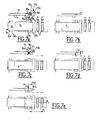
- the non-demoldable pots 8a to 8f may have varied and complex shapes, and may be covered with a D: cylindrical decoration with a variable diameter (FIG. 2d) or with a troncocylindrical K neck (FIG. FIG. 2a) with screwed parts (FIG. 2f), cubic with possibly a hollow central part (FIG. 2e), or else spherical with a decoration D (FIG. 2b), spherical without decoration (FIG. 2g) or conical (FIG. ), or any other moldable form.
- the pots are closed by a lid O p welded to the flange C. It can thus be seen that screw threads can be produced, and that lateral decorations can also be deposited, the method according to the invention being compatible with decoration devices by streamer introduced into the mold before forming.
- thermoformable sheet 1 is fed from a reel 3 and cut into sections 4 by cutting means 6.
- the sections are driven by a transport chain 10 with pins 12, and then processed into successive posts by the various integrated thermoforming tools: heating boxes 5 of the sheet and the thermoforming molds 7 of the pots 8 (with molds, counter-molds and punches), the doser 9 of the contents of the pots, the sealing station equipped with welding electrodes 11 of the operculum foil 2, and the final cutting station equipped with cutting tools 13 pots per unit or pack.
- the treatment is at a continuous rate and allows you to end of treatment cycle, from one row of pots 8 to another.
- the integrated thermoforming tools treat pots to reason one row R per cycle and 6 pots per row.
- this machine comprises in particularly the cutting means 6 of the sheet 1 in rectangular sections 4, upstream of the treatment stations.
- the rectangle shape can be advantageously replaced by other forms, for example: parallelogram, trapezium, etc., to adapt to particular cases.
- the step P2 plastic is equal to P1 - E.
- treatment is performed at each of the posts by the molds 7 and the welding tools 11 and final cut 13 concerned to move from the work conformation, with a clutter minimum 7h, 11h and 13h, with the open conformation in transfer position of a station to another, with a respective maximum congestion 7b, 11b and 13b.
- the step P1 of the operating cycle of the machine and the cutting means 6 is barely greater than that of the openings of the means which has, in transfer position, the largest longitudinal dimension along the general direction F of the machine of transport, hereinafter maximum opening.
- the width P2 of each section of thermoformable material is 60 mm, corresponding substantially at the greatest width of the tools in the closed position of work, and the P1 machine pitch is set barely higher than the opening maximum processing tools (that of the release of the pots in the example), which is 100 mm, corresponding to the maximum width of tools in working position (60 mm) increased by two half-openings (twice 20 mm) of the half - tools of the maximum opening.
- the machine can be advantageously adapted to the treatment several rows of pots per operating cycle.
- the machine pitch P1 is equal to P2 + E, P2 being the plastic step or, already called, not material, and E the space between two sections of material. More generally, in the case of treatment with n rows of pots, the machine pitch is equal to n (P2 + E).
- the molds and treatment tools 7 ', 9', 11 'and 13' are doubled at each post.
- the displacement of the driven sections is then doubled and is, for example, of value barely greater than the opening maximum doubled 7'b of space tools 7'b, 9'b, 11'b and 13'b.
- the cutting means 6 of the sheet of material 1 are constituted by the guillotine 17, a shear or a wheel, associated with a anvil, one or more counter-blades, or a support matrix 19.
- the reference phase ( Figure 5a) represents the end of a cycle previous.
- the guillotine 17 is constituted of the matrix19, support of the sheet 1, and cutting blades 18, 21 driven by moving means perpendicular to the thermoforming sheet.
- Means for removing the cut sections are integral with the blade in the illustrated example, but can also be independent in other embodiments. In alternatively, other means of removal and positioning, such as suction carriages, ramps or slides, may be provided.
- the sheet is advanced (arrow H) by the rotational drive means 30 of the coil 3.
- the guillotine also has pre-cut blades 21 of the leaf, which act upstream of it. The function of these pre-cutting blades is making cuts in areas of the sheet for pecking, to avoid interference between the main blade and the sprocket chain.
- each section 4 is cut by vertical displacement (arrow F1) of the main blade 18 and pre-cutting blades 21 (arrow F2).
- the pre-cutting blades 21, controlled independently of the blade 18 in the example (but the blades can be single-commanded in other examples), are provided for forming two end cuts 22 in the sheet at the step preceding the step of section 4. These pre-cuts act on the entire thickness of the sheet to obtain a complete cut of the sheet in not cutting.
- the positioning of the sections 4 is achieved by combination with the pressing means of removal, in this embodiment. of the removal means can also serve as positioning means, such as clamps or mobile ramps.
- the picotage phase is more precisely illustrated in FIG. 5d.
- the press 23 drives (arrow F3, Figure 5d) the section 4 cut against the transport chain 10, and holes the section through the pins 12. To avoid interfere with the pins, the blade 18 and the press 23 are calibrated transversely so as not to interfere with the pins 12.
- FIGS. 6a to 6c show, in front view, the press 23 and the chain 10 provided with its pins 12, during three phases of operation.
- the section 4 presents itself with regard to the pins 12 of the chain 10.
- the press 23 is then actuated to push (arrows F3) the stretch on the pins 12 that pass through the plastic material and come to housed in clearance grooves 23a of the press 23 ( Figure 6b).
- the press 23 is actuated to go back to the initial level (arrow F4, FIG. 6c).
- the press means are separated from the blade and stroke cutting means is then limited to the necessities of the complete cut of the section.
- the pre-cut blades can then be deleted.
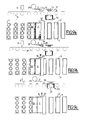
- Figures 7a to 7e show, in a similar way to FIGS. 5a to 5e, the five operating phases of cutting means lined for two thermoformable sheets of a machine adapted to the deposit two sections per machine step.
- two feed coils 3a are provided. and 3b, driven by means 30a, 30b for feeding two sheets of thermoformable material, respectively 1a and 1b, two cutting tools and deposit 17a and 17b, respectively comprising the support matrices 19a and 19b, the blades 18a and 18b, and the presses 23a and 23b.
- Pimples 12 of the sections, respectively 4a and 4b, are also provided.
- the sheets and the cutting means are superposed without contact and offset in the direction of movement F of a half-pitch machine P1 / 2 for respect the machine pitch P1 ( Figure 7e) of the example, very slightly greater than 200 mm (200 + ⁇ ).
- FIGS. 8a to 8f illustrate, in views schematic upper and lateral, six phases of operation of thermoformable sheet cutting means for a machine adapted to the cutting and deposition of two sections by machine step, but with coil single feed.
- FIG. 8a shows a reference state corresponding to the end of a previous cycle, which allowed the cutting of two sections 4a and 4b with a single cutting and removal tool, a guillotine 17 including the blade 18, the press 23 and the die 19.
- the leaf deformable In the preparation phase of the first cut, the leaf deformable is advanced according to the arrow F with a plastic pitch P2 of 60 mm ( Figure 8b). Then, in the cutting phase (FIG. 8c), the blade 18 and the press 23 are moved vertically in the low position (arrow V), the press descending at the level of the drive chains for removal. A section 4a is thus sliced and deposited.
- the sheet is advanced, by order of the means training 30 of the coil 3, a plastic pitch P2 increased by a half-step machine P1 / 2 (or P1 - E).
- the section 4b is then cut (FIG. 8f) and deposited by respective lowering of the blade 18 and the press 2 (arrow V). during the advance of the chain, so in masked time (0.5 s in the example), the blade-press assembly is then reassembled, the cutting tool moved to the rear (arrow H 'opposite the arrow H) of a half-pitch P1 / 2 and the coil plastic moves back a distance equal to the space E, to return to the state of reference of Figure 8a.
- the cutting tool is equipped with two blades for cutting two adjacent sections. These sections are positioned by sloping rails or ramps that carry each section of the "high" cutting position at the "low” picot sliding. For example, if the space E between sections is 40 mm, the sliding means position the first section of 20 mm in the direction the advance of the plastic sheet, while the second section slides 20 mm in the opposite direction.
- the section cutting tool is equipped with as many blades as sections to be cut, that is to say that rows of pots per step, and each section is brought into position then deposited on the means of advance (chain with pins, for example) by the use as many positioning trays (sucker trays, for example).
- the operculum material may advantageously, also cut into sections, according to a geometry identical or similar to that used in the cut into sections of the forming sheet by equivalent cutting means. Such a cut also allows to eliminate the losses of the operculum material between two rows of pots.
- Figures 9a to 9e illustrate, in schematic views superior and lateral, five phases of implementation of the operations of cutting and removal of the operculum material in sections 4 '.
- Reference Figure 9a shows a supply coil 25 operculum material 2 coupled to a cutting tool 17, similar to previous cutting tools.
- the coil 25 is disposed between the dosing pots 8 formed from sections 4, comprising the doser volumetric 9, and the welding station, comprising a welding press 11 composed of an upper cross member 11s for supporting the electrodes 14 and a lower cross member 11i support the counter electrode.
- the operculum sheet 2 is cut in section 4 'by lowering the blade 18, the section being deposited on the thermoforming material 1 by lowering the press 23 of the cutting tool 17.
- the lower cross-member 11i is raised (arrow V) in the same phase in order to prepare the welding sealing phase during the next phase.
- the positioning of the sections operculum is made by pre-sealing by welding means (no represented by points 27 of the sections 4 'of operculum material on the sections of plastic material 4.
- Welding points are located in the waste areas of the unused lid material, typically called the grid, in the case of a grid cut, or the stars, in the case of a cut without grille to round the corners of the flanges.
- This pre-welding serves to drive the sections of seal material properly positioned to the welding station pots.
- the sealing itself is initiated by closing the welding press by horizontal displacement (arrows H1 and H2) of the walls 11l of the lower cross member 11i and a lowering (arrow V ') of the upper rail 11s. Electrodes previously raised to high temperature (for example at 200 ° C.), result in the melting of a lacquer contained in the lid, or self-sealing materials, for example polyethylene on polyethylene.
- the final phase ( Figure 9e) consists of raising the blade of cut 18 and the press 23 (arrow V) of the cutting tool 17, and to open the solder press 11 by displacement of the top rail 11s (arrow V), walls 11l (arrows H '1 and H'2) and bottom rail 11i (arrow V ').
- the welding station then returned to the reference conformation (FIG. 9a).
- the material cutting system operculum may comprise as many coils as rows of pots to be treated, or a single coil for several rows with successive cutting (and positioning) or simultaneously (with feeding into position) as for the deformable material.
- the cutting and dispensing operations of operculum material are conducted laterally in accordance with the figures 10a to 10c as part of a treatment pots in rows of two.
- This variant is particularly suitable when the machine can handle simultaneously several rows of pots to increase its capacity.
- the welding station of the material operculum consists of a welding press 11 ', consisting of a upper cross 11 ', and a lower cross 11'i, forming a tool double.
- the supply reel 25 of the operculum sheet 2 is arranged so that its axis X'X is parallel to the direction of displacement F of the transport chain 10. The sheet is thus unrolled parallel to the rows R pots 8.
- a blade system 29 can split the sheet 2 longitudinally. The multiplication of this blade system allows more generally, to split the operculum leaf into as many sections as rows of pots to treat.
- the two streamers formed 2a and 2b are arranged above sections 4 of deformable material by advancing means side and cut by a cutting tool 17 blade 18 on a counterblade 33 to form sections of operculum 4 '.
- Separation guides trained by rollers T1 to T4 in the example shown, allow to separate the streamers after twisting.
- Figure 10b illustrates the placement of streamers operculum material 2a and 2b.
- the means sideways, in the form of rolls T5 and T6 push the streamers transversely (arrows T) in relation to the direction of advance pots to direct them to the forming sections.
- Means of guiding formed by slides 31 and 32 position the sections of opercle 4 'with regard to sections 4 of rows of corresponding pots
- the operculum streamers are cut into 4 'sections by the cutting tool 17 (FIG. 10c), the welding press 11 is closed to proceed to the welding of the sections of lid (arrows H'1, H'2, V and V ') and the dosing of the products is carried out at the dosing station 9.
- the streamers are welded directly on the sections 4.
- a return to conformation illustrated by the Figure 10a is performed.
- the final cut advantageously allows to obtain, particularly in the case of multiple row processing, single or packaged pots, as shown in Figures 11a to 11c.
- the cutting is performed by blade tools positioned to form pots 8 (FIG. 11a) packs 35 of 2 pots 8 (FIG. 11b) or packs 37 of 3 pots (Figure 11c) according to the illustrated examples.
- FIGS. 12a and 12b there is schematically illustrated the material gain obtained with the manufacturing process according to the invention for the manufacture of a pot 8g, the type of that illustrated in Figure 2g for example.
- P2 (aa) of the prior art
- just a section of material width equal to step P2 significantly less than P2 (aa), which corresponds to a gain of material G1 + G2 equal to the space E mentioned above.
- the pitch P2 of the plastic section may be adjusted, in certain cases, so as to be substantially equal to the width of the flange C, and therefore substantially less wide than the belly Ve pot 8g: we can then speak of negative losses, m 1 + m 2 , between the width of the section of plastic and that of the belly Ve, with respect to the width of the section in the case of Figure 12a.
- thermoforming is replaced by a system of deformation of the metal by mechanical punching with optional gas or liquid pressure.
Abstract
Description
L'invention concerne un procédé de fabrication de pots non démoulables par formage intégré sans perte notable de matériau, ainsi que la machine de mise en oeuvre d'un tel procédé.The invention relates to a method of manufacturing pots which are not can be removed by integrated forming without significant loss of material, as well as machine for implementing such a method.
Pour fabriquer des pots, en particulier des pots de produits
alimentaires ou autres, une technique traditionnelle, illustrée en figure 1, utilise
le formage intégré. Il consiste à prévoir le traitement, par exemple d'une feuille
plastique thermoformable 1, par cycle, par poste et par groupe de pots. La
feuille, enroulée autour d'une bobine 3, est déroulée longitudinalement selon
une bande continue et traitée successivement en différents postes,
équipés respectivement : de moyens de chauffage de la feuille 5, de moules
de formage 7 des pots 8, de moyens de dosage 9 du contenu des pots,
d'outillages de soudure 11 de la feuille d'opercule 2 et de découpe finale 13
par pot unitaire ou par pack de pots.To make pots, especially pots of produce
food or other, a traditional technique, illustrated in Figure 1, uses
integrated forming. It consists in providing the treatment, for example of a sheet
Le traitement est continu en déplacement longitudinal grâce à
un dispositif d'avance 15. Un convoyeur de réception 16 est disposé en sortie.
Les moyens d'avance permettent de passer, à chaque fin de cycle machine,
d'une ou plusieurs rangées transversales R de pots par pas à une autre, en
avançant d'une longueur de déroulement de la bobine correspondant à un pas
dit pas machine P1.The treatment is continuous in longitudinal displacement thanks to
an
Le pas machine P1 coïncide dans ce cas avec le pas de la feuille plastique P2, dit pas matériau, qui correspond à la largeur de la zone de la feuille plastique dans le sens de l'avance, nécessaire aux traitements des différentes opérations aux différents postes.The pitch machine P1 coincides in this case with the pitch of the P2 plastic sheet, not called material, which corresponds to the width of the area of the plastic sheet in the sense of advance, necessary for the treatment of different operations at different positions.
Cependant les pots peuvent présenter des formes de plus en plus variées, avec en particulier des contre-dépouilles importantes. Il s'en suit qu'ils ne sont pas démoulables sans ouverture des moules au droit du poste de formage et, éventuellement, qu'ils ne sont pas dégageables au droit d'autres postes d'outillage (soudure ou découpe), notamment chaque fois qu'un "col" du pot en partie supérieure est de dimension inférieure à celle du "ventre" du pot.However, pots can have more and more shapes more varied, with in particular significant undercuts. It follows they are not demoldable without opening the molds to the right of the post of forming and, possibly, that they are not disengageable in other tooling stations (welding or cutting), in particular each time a "neck" of the pot in the upper part is smaller than the "belly" of the pot.
Ainsi, en fin de traitement, les moules ou, éventuellement, les
contre - électrodes de soudure ou les matrices, en conformation fermée en
position de travail (pour le formage, la soudure ou la découpe finale) avec un
encombrement 7h, sont ouverts longitudinalement en passant en position de
transfert d'un poste à l'autre avec un encombrement 7b; de même, les
outillages de soudure et de découpage, en conformation fermée en position
de travail, avec un encombrement respectif 11h et 13h, sont ouverts en
position de transfert avec un encombrement longitudinal 11b et 13b. Afin
d'éviter les interférences entre les outillages, ou entre les outillages et les
empreintes formées, un espace longitudinal E suffisant doit être prévu entre
les rangées R de pots.Thus, at the end of treatment, the molds or, possibly, the
counter welding electrodes or dies, in closed conformation
working position (for forming, welding or final cutting) with a
7h space, are opened longitudinally while passing in position of
transfer from one station to another with a
Les pas machine P1 et plastique P2 étant directement fonction de l'espace E, il en résulte une perte importante de matériau thermoformable et de matériau d'opercule entre les rangées de pots, du fait que la partie des feuilles correspondant aux espaces E, ne sera pas utilisée pour faire des pots.The machine P1 and plastic P2 steps being directly function space E, this results in a significant loss of thermoformable material and operculum material between the rows of pots, since the portion of leaves corresponding to spaces E, will not be used to make pots.
Pour remédier à ce gaspillage, il a été proposé d'utiliser deux machines, une première machine pour former et découper les pots, puis une seconde machine de remplissage. Cette technique présente au moins deux inconvénients majeurs :
- les modes de prise en charge n'étant pas continus entre les deux machines, - des pots individuels succédant à une bande de matériau continu -, une rupture de prise en charge se produit nécessairement même si les machines sont intégrées ;
- un système à opercules prédécoupés est peu économique : le pré-découpage nécessite des matériaux d'opercule plus coûteux et une logistique complexe et coûteuse, avec la mise en oeuvre de moyens de stockage et de déstockage dans des magasins d'alimentation dédiés, faisant intervenir des dispositifs automatiques complexes et délicats, ou une main d'oeuvre continue et astreignante.
- the management modes not being continuous between the two machines, - individual pots succeeding a strip of continuous material - a failure of support necessarily occurs even if the machines are integrated;
- a pre-cut seal system is uneconomical: pre-cutting requires more expensive operculum materials and complex and expensive logistics, with the implementation of storage and retrieval means in dedicated food stores, involving complex and delicate automatic devices, or a continuous and exacting work force.
Une autre solution consiste à étirer périodiquement la feuille de sorte que l'espace E obtenu a une épaisseur de matière sensiblement plus faible, ce qui limite, d'autant, la quantité de matière thermoformable perdue. Ce procédé est délicat à mettre en oeuvre. De plus, il ne réduit pas les pertes en matériau d'opercule lorsqu'il se présente, traditionnellement, en rouleaux longitudinaux, ou augmente sensiblement les coûts, en matériau d'opercule et en logistique, lorsqu'il se présente sous forme d'opercules prédécoupés.Another solution is to stretch the sheet periodically so that the E space obtained has a substantially greater material thickness low, which limits the amount of thermoformable material lost. This process is difficult to implement. In addition, it does not reduce losses in operculum material when it is traditionally in rolls longitudinals, or substantially increases the cost, of a cover material and in logistics, when it comes in the form of pre-cut lids.
La présente invention vise à supprimer totalement les pertes de matière de formage et/ou d'operculage entre deux rangées, ou une très grande partie de ces pertes, tout en conservant les avantages du thermoformage intégré. Pour ce faire, il est procédé à une coupe de la feuille en tronçons et à un positionnement approprié de ces tronçons par rapport aux outillages successifs.The present invention aims to completely eliminate losses of forming material and / or sealing between two rows, or a very much of these losses while retaining the benefits of integrated thermoforming. To do this, the sheet is cut in sections and to an appropriate positioning of these sections with respect to successive tools.
Plus précisément, l'invention a pour objet un procédé de fabrication de pots non démoulables par formage intégré comportant des outillages de traitement successifs d'au moins une feuille de matériau d'emballage, ces outillages présentant une ouverture de conformation variable en fonctionnement, le procédé consistant à prévoir une coupe préliminaire de la feuille d'emballage en tronçons selon une géométrie appropriée aux outillages de traitement, chaque tronçon du matériau étant coupé selon un pas matériau réglé pour être égal à très peu supérieur à la largeur de matériau nécessaire au traitement de formage ou d'operculage sans tenir compte de l'ouverture des outillages, puis à positionner successivement les tronçons pour les faire avancer de manière espacée selon un pas machine, le pas machine étant égal à très peu supérieur à la largeur d'outillage la plus importante en position ouverte de transfert.More specifically, the subject of the invention is a method of manufacture of non-moldable pots by integrated forming including successive processing tools of at least one sheet of material packaging, these tools having an opening of variable conformation in operation, the method of providing a preliminary cut of the packing sheet in sections according to a geometry appropriate to the processing tools, each section of the material being cut according to a step material set to be equal to very little greater than the width of material necessary for the forming or sealing process without taking into account opening of the tools, then successively positioning the sections for to advance them in a spaced way according to a not machine, not the machine being equal to very little greater than the largest tooling width in open transfer position.
L'expression « très peu supérieur » est introduite pour justifier des tolérances à prévoir afin d'être assuré de disposer de suffisamment de matériau pour réaliser l'emballage, et de suffisamment de jeu pour le fonctionnement des outillages.The expression "very little superior" is introduced to justify tolerances to be provided in order to be sure of having enough material to achieve the packaging, and enough play for the tooling operation.
Le formage peut être réalisé à chaud, à partir de matériau de thermoformage, ou à froid.The forming can be carried out hot, from material of thermoforming, or cold.
L'invention s'applique aussi bien au formage qu'à l'operculage intégré des pots par découpe de la feuille de formage et/ou d'operculage selon une géométrie semblable. Le gain de matière correspond, dans les deux cas, sensiblement à l'espace de matière entre deux rangées de pots de l'art antérieur, puisque la matière étant quasi totalement utilisée selon la présente invention y compris, éventuellement, en deçà des "ventres" si la dimension de la "collerette" des pots le permet.The invention applies both to forming and to lidding integrated pots by cutting the forming sheet and / or lidding according to a similar geometry. The material gain corresponds, in both cases, substantially to the material space between two rows of art jars previous, since the material is almost completely used according to the present including, possibly, below the "bellies" if the dimension of the "collar" of the pots allows it.
Dans ces conditions, les avantages du formage intégré sont conservés, avec notamment un processus permettant la prise en charge continue d'une ou plusieurs rangées de pots par cycle sur chacun des postes de la machine, tout en supprimant toutes les pertes, ou au moins une grande partie des pertes, des matériaux de formage et d'opercule.In these conditions, the advantages of integrated forming are preserved, including a process for the management of continue one or more rows of pots per cycle on each of the stations of the machine, while removing all losses, or at least a large part of the losses, forming and sealing materials.
L'invention concerne également une machine de mise en oeuvre du procédé. Cette machine comporte des moyens de coupe en tronçons d'au moins une feuille de matériau de formage et/ou d'operculage alimentée(s) à partir d'au moins une bobine, chaque tronçon ayant une largeur selon une direction de traitement égale à un pas matériau, des moyens de dépose régulière de chaque tronçon à une distance constante définissant un espace entre les tronçons et de transport de ces tronçons à différents postes de traitement, à raison d'autant de tronçons que de rangées de pots à fabriquer par pas machine, ces postes comportant, successivement selon une direction de traitement, au moins des outillages de formage, de dosage, de soudure et de découpe finale des pots, ces outillages pouvant passer d'une conformation fermée à ouverte en position de travail ou de transfert d'un poste à l'autre, le pas matériau étant réglé pour être égal à très peu supérieur à la largeur de matériau nécessaire au formage ou à l'operculage sans tenir compte de l'ouverture des outillages, et le pas machine étant égal à très peu supérieur à la largeur d'outillage la plus importante en conformation ouverte.The invention also relates to a setting machine process. This machine comprises cutting means in sections of at least one sheet of forming and / or sealing material powered from at least one coil, each leg having a width according to a treatment direction equal to a material pitch, means of regular removal of each section at a constant distance defining a space between the sections and transport these sections to different positions of treatment, as many sections as rows of pots to machine-made, these positions comprising, successively according to a treatment direction, at least one of the tools for forming, dosing, welding and final cutting pots, these tools can pass from a closed to open conformation in working position or transfer of a post to the other, the material pitch being set to be equal to very little higher than the width of material required for forming or sealing without taking into account account of the opening of the tools, and the machine pitch being equal to very little greater than the largest tooling width in open conformation.
Selon des modes particuliers de réalisation :
- le matériau d'emballage est le matériau de formage des pots et/ou le matériau d'opercule, selon une géométrie semblable à celle ajustée au formage, afin de supprimer les pertes du matériau de formage et/ou d'opercule entre deux rangées de pots à traiter ;
- chaque pas machine traite, selon les besoins, de 1 à
plusieurs rangées de pots à fabriquer à la fois, par
exemple - les moyens de transport des tronçons de matériau de formage sont avantageusement constitués par une chaíne à picots ;
- les moyens de coupe des tronçons sont constitués par une matrice support de la feuille associée à au moins une lame ou une molette entraínée par des moyens de déplacement perpendiculairement à la feuille de formage ;
- le picotage des tronçons de feuille est réalisé par des moyens presseurs qui sont soit combinés aux moyens de coupe, dans ce cas les moyens de coupe ont un gabarit limité par la présence des moyens de transport pour ne pas interférer avec ces moyens de transport, soit séparés de ces moyens, la course des moyens de coupe étant alors limitée aux nécessités de la coupe ;
- des moyens de pré-découpe de la feuille de formage sont avantageusement prévus en combinaison avec les moyens de coupe dans le cas d'un gabarit limité, pour former des pré-découpes d'extrémité dans la feuille au pas précédent le pas de coupe, les moyens de pré-découpe agissant sur toute l'épaisseur de la feuille afin d'obtenir une découpe complète de la feuille au pas de coupe ;
- lorsque le pas machine traite deux rangées de pots, il peut être prévu une seule bobine d'alimentation en feuille de formage et un seul moyen de coupe, le moyen de coupe avance d'un demi-pas machine après découpe du premier tronçon de chaque pas et la bobine avance d'un pas plastique augmenté d'un demi-pas machine pendant l'arrêt de la chaíne, puis l'outil de coupe recule d'un demi-pas machine et la bobine recule de l'espace entre tronçons, pendant l'avance de la chaíne, en temps masqué ;
- alternativement, dans ce même cas de traitement deux rangées de pots avec une seule bobine d'alimentation en feuille de formage et un seul moyen de coupe, le moyen de coupe recule d'un demi-pas machine après découpe du premier tronçon de chaque pas et la bobine recule d'un espace entre tronçons, pendant l'arrêt de la chaíne, puis l'outil de coupe avance d'un demi-pas machine et la bobine avance d'un pas plastique augmenté d'un demi-pas machine, pendant l'avance de la chaíne, en temps masqué ;
- lorsque le pas de cycle correspond à n rangées de pots, il peut être prévu une seule bobine d'alimentation et un seul moyen de coupe fonctionnant comme précédemment, ou bien autant de moyens d'alimentation en feuilles de formage et de moyens de coupe de ces feuilles en tronçons, décalés de la valeur P1/n;
- le matériau d'opercule est alimenté en bande à partir d'une bobine, puis découpé en tronçons de dimensions semblables à celles des tronçons du matériau de formage; outre l'aspect économique, une telle alimentation présente l'avantage, par rapport à l'alimentation classique en morceaux prédécoupés et alimentés à partir d'un magasin de stockage, de permettre une stérilisation avant ou après tronçonnage par rayonnement (ultraviolet, de type flash, infrarouge, etc.), ou par traitement chimique continu, alors qu'il est très difficile de stériliser juste avant soudure des opercules unitaires de l'état de la technique ;
- des moyens de pré-découpe du matériau d'opercule semblables aux moyens de pré-découpe de la feuille de formage forment des tronçons de matériau d'opercule qui sont pré-soudées par points sur les tronçons de matériau déformable, pour entraíner les tronçons de matériau d'opercule jusqu'au poste de soudure et réaliser l'operculage des pots ;
- alternativement, des moyens de découpe fendent préalablement la feuille d'operculage en autant de banderoles que de rangées de pots à traiter simultanément, puis des moyens de vrillage et d'avancée latérale amènent les banderoles dans des glissières de positionnement pour que des moyens de découpe tranches les banderoles en tronçons sur chaque tronçon de feuille déformable ; cette solution convient en particulier lorsque le pas machine traite au moins 2 rangées de pots par pas ;
- le formage peut être réalisé à chaud, à partir de matériau thermoformable, ou à froid, par déformation d'une feuille de métal, par exemple par poinçonnage d'une feuille d'aluminium.
- the packaging material is the pot forming material and / or the cap material, in a geometry similar to that fitted to the forming, in order to eliminate the losses of the forming material and / or the seal between two rows of pots to be treated;
- each machine step processes, as required, from 1 to several rows of pots to manufacture at a time, for example 2, 3, 4 or more, allowing the continuous handling of one or more rows of pots per cycle on each machine stations;
- the means of transport of the sections of forming material are advantageously constituted by a chain with pins;
- the cutting means of the sections consist of a support matrix of the sheet associated with at least one blade or a wheel driven by displacement means perpendicular to the forming sheet;
- the potting of the sheet sections is carried out by pressing means which are either combined with the cutting means, in this case the cutting means have a size limited by the presence of the means of transport so as not to interfere with these means of transport, either separated from these means, the stroke of the cutting means being then limited to the necessities of cutting;
- pre-cutting means of the forming sheet are advantageously provided in combination with the cutting means in the case of a limited jig, to form end pre-cuts in the sheet at the pitch preceding the cutting pitch, the pre-cutting means acting over the entire thickness of the sheet in order to obtain a complete cutting of the sheet at the cutting pitch;
- when the machine step processes two rows of pots, it can be provided a single forming sheet feed reel and a single cutting means, the cutting means advances a half machine step after cutting the first section of each step and the coil advances with a plastic step increased by a half-step machine during the stop of the chain, then the cutting tool moves back half a step machine and the coil moves back space between sections during the advance of the chain, in masked time;
- alternatively, in the same case of treatment two rows of pots with a single forming sheet feed coil and a single cutting means, the cutting means moves back a half machine step after cutting the first section of each step and the coil retracts a space between sections, during the stop of the chain, then the cutting tool advances by half a machine step and the coil advances with a plastic step increased by a half-step machine during the advance of the chain, in masked time;
- when the cycle step corresponds to n rows of pots, it can be provided a single supply reel and a single cutting means operating as before, or as many feed means forming sheets and cutting means of these sheets in sections, offset by the value P1 / n;
- the cover material is strip-fed from a spool, then cut into sections of similar dimensions to those of the forming material sections; in addition to the economic aspect, such a supply has the advantage, compared to the conventional supply of pre-cut pieces and fed from a storage magazine, to allow sterilization before or after radiation cutting (ultraviolet, type flash, infrared, etc.), or by continuous chemical treatment, while it is very difficult to sterilize just prior to welding unitary lids of the state of the art;
- pre-cutting means of the operculum material similar to the pre-cutting means of the forming sheet form sections of operculum material which are pre-welded by points on the sections of deformable material, to drive the sections of seal material to the sealing station and seal the pots;
- alternatively, cutting means pre-slit the sealing foil in as many streamers as rows of pots to be treated simultaneously, and twisting means and lateral advance bring the streamers in positioning slides so that the cutting means slice the streamers into sections on each section of deformable sheet; this solution is particularly suitable when the machine step treats at least 2 rows of pots per step;
- the forming can be carried out hot, from thermoformable material, or cold, by deformation of a sheet of metal, for example by punching an aluminum foil.
D'autres avantages et caractéristiques de la présente invention apparaítront à la lecture de la description qui suit, relative à des exemples de réalisation non limitatifs, en référence aux figures annexées qui représentent, respectivement :
- la figure 1, une vue schématique supérieure d'une machine de thermoformage intégré pour pots non démoulables, selon l'état de la technique (commentée ci-dessus) ;
- les figures 2a à 2g, des vues de face, d'exemples non exclusifs, de pots non démoulables ;
- la figure 3, une vue schématique supérieure et partiellement de côté d'une machine de thermoformage intégré selon l'invention, avec une rangée de pots traitée par cycle;
- la figure 4, une vue schématique supérieure et partiellement de côté de la machine selon la figure précédente, adaptée au traitement de deux rangées de pots par cycle ;
- les figures 5a à 5e, en vues schématiques supérieures et de côté, le fonctionnement des moyens de coupe de feuille thermodéformable d'une machine selon l'invention, dans le cas d'une seule bobine et d'une seule rangée par cycle ;
- les figures 6a, 6b et 6c, en vue schématique de face, trois phases de picotage de la feuille thermoformable;
- les figures 7a à 7e, en vues schématiques supérieures et de côté, cinq phases de fonctionnement des moyens de coupe de feuilles thermoformables à deux bobines d'alimentation, pour une machine adaptée au dépôt et traitement de deux tronçons par pas machine ;
- les figures 8a à 8f, en vues schématiques supérieures et de côté, six phases de fonctionnement des moyens de coupe de feuille thermoformable à bobine d'alimentation unique, pour une machine selon l'invention adaptée au dépôt de deux tronçons par pas machine ;
- les figures 9a à 9e, en vues schématiques supérieures et de côté, cinq phases de réalisation des opérations de découpe et de dépose du matériau d'opercule, dans le cas d'une bobine unique pour la soudure d'un tronçon d'opercule par pas machine ;
- les figures 10a à 10c, en vues supérieures, de côté et rabattue, trois phases des opérations de découpe et de dépose du matériau d'opercule selon une variante de réalisation, dans le cas d'une bobine unique pour la soudure de deux tronçons d'opercule par pas machine ;
- les figures 11a à 11c, des vues schématiques supérieures
de découpe finale de la machine selon la figure précédente, adaptée
respectivement à la découpe unitaire de pot, à la découpe de packs
de 2 et de 3 pots ; et - les figures 12a et 12b, des vues en plan schématique pour illustrer le gain de matière obtenu avec le procédé selon l'invention par rapport à la technique antérieure.
- Figure 1 is a schematic top view of an integrated thermoforming machine for non-moldable pots, according to the state of the art (commented above);
- Figures 2a to 2g, front views, non-exclusive examples, non-demoldable pots;
- FIG. 3 is a diagrammatic view of the upper side of an integrated thermoforming machine according to the invention, with a row of pots treated per cycle;
- FIG. 4, an upper schematic and partially side view of the machine according to the previous figure, adapted to the treatment of two rows of pots per cycle;
- FIGS. 5a to 5e, in schematic top and side views, the operation of the heat-deformable sheet cutting means of a machine according to the invention, in the case of a single coil and a single row per cycle;
- Figures 6a, 6b and 6c, in schematic front view, three picotage phases of the thermoformable sheet;
- FIGS. 7a to 7e, in schematic top and side views, five operating phases of the thermoformable sheet cutting means with two feed rolls, for a machine adapted to the deposition and treatment of two sections by machine step;
- FIGS. 8a to 8f, in schematic top and side views, six operating phases of the thermoformable sheet cutting means with single feed reel, for a machine according to the invention adapted to the deposition of two sections by machine step;
- FIGS. 9a to 9e, in schematic top and side views, five phases of carrying out the operations of cutting and depositing the lid material, in the case of a single coil for the welding of a seal section by not machine;
- FIGS. 10a to 10c, in upper views, from the side and folded down, three phases of the cutting and removal operations of the cover material according to an embodiment variant, in the case of a single coil for welding two sections of operculum by machine step;
- Figures 11a to 11c, schematic views of the final final cut of the machine according to the previous figure, respectively adapted to the unit cut pot, the cutting packs of 2 and 3 pots; and
- Figures 12a and 12b, schematic plan views to illustrate the material gain obtained with the method according to the invention compared to the prior art.
Les signes de référence identiques désignent, sur les figures, des éléments identiques ou correspondants.The identical reference signs designate, in the figures, identical or corresponding elements.
En référence aux figures 2a à 2g, les pots non démoulables,
respectivement 8a à 8f, peuvent présenter des formes variées et complexes,
et peuvent être recouverts d'un décor D : cylindrique à diamètre variable
(figure 2d) ou à col K troncocylindrique (figure 2a) avec parties à vis (figure 2f),
cubique avec éventuellement une partie centrale en creux (figure 2e), ou bien
encore sphérique avec un décor D (figure 2b), sphérique sans décor
(figure 2g) ou conique (figure 2c), ou tout autre forme moulable. Les pots sont
fermés par un opercule Op soudé sur la collerette C. On voit ainsi que l'on peut
réaliser des pas de vis, et que l'on peut également déposer des décors
latéraux, le procédé selon l'invention étant compatible avec les dispositifs de
décoration par banderole introduits dans le moule avant formage.With reference to FIGS. 2a to 2g, the
Les contre - dépouilles importantes liées à la plupart de ces formes, en particulier chaque fois qu'un col K du pot est de dimension inférieure à celle du « ventre » Ve du pot ne les rendent pas démoulables au droit du poste de formage et, éventuellement, non dégageables au droit d'autres postes d'outillage (soudure ou découpe).The large undercuts associated with most of these forms, in particular each time a neck K of the pot is smaller than that of the "belly" V e of the pot do not make them demoldable to the right of the forming station and , possibly, non-disengageable to the right of other tooling stations (welding or cutting).
Pour fabriquer ces pots selon l'invention, comme illustré en
figure 3, une feuille thermoformable 1 est débitée à partir d'une bobine 3 puis
découpée en tronçons 4 par des moyens de coupe 6. Les tronçons sont
entraínés par une chaíne de transport 10 à picots 12, puis traitée en des
postes successifs par les différents outils du thermoformage intégré : les
boítes de chauffe 5 de la feuille et les moules de thermoformage 7 des pots 8
(avec moules, contre-moules et poinçons), le doseur 9 du contenu des pots, le
poste d'operculage équipé d'électrodes de soudure 11 de la feuille d'opercule
2, et le poste de découpe final muni d'outils de découpe 13 des pots par unité
ou pack. Le traitement est à cadence continue et permet de passer, à chaque
fin de cycle de traitement, d'une rangée de pots 8 à une autre. Dans ce
premier exemple, les outils de thermoformage intégré traitent les pots à raison
d'une rangée R par cycle et de 6 pots par rangée.To manufacture these pots according to the invention, as illustrated in
3, a
Conformément à l'invention, cette machine comporte en
particulier les moyens de coupe 6 de la feuille 1 en tronçons rectangulaires 4,
en amont des postes de traitement. La forme en rectangle peut être
avantageusement remplacée par d'autres formes, par exemple:
parallélogramme, trapèze, etc., pour s'adapter à des cas particuliers. Dans le
cas d'un traitement de la machine par rangée unique de pots par cycle, le pas
plastique P2 est égal à P1 - E. La matière plastique correspondant à l'espace
E dans le cadre du procédé classique illustré en figure 1, est ainsi
économisée.According to the invention, this machine comprises in
particularly the cutting means 6 of the
A chaque cycle, un traitement est effectué à chacun des
postes par les moules 7 et les outils de soudure 11 et de découpe finale 13
concernés pour passer de la conformation de travail, avec un encombrement
minimal 7h, 11 h et 13h, à la conformation ouverte en position de transfert d'un
poste à l'autre, avec un encombrement maximal respectif 7b, 11b et 13b.At each cycle, treatment is performed at each of the
posts by the molds 7 and the
Le pas P1 du cycle de fonctionnement de la machine et des moyens de coupe 6 est à peine supérieur à celui des ouvertures des moyens de traitement qui présente, en position de transfert, le plus grand encombrement longitudinal selon la direction générale F de la machine de transport, ci-après ouverture maximale. Dans cet exemple, la largeur P2 de chaque tronçon de matériau thermoformable est de 60 mm, correspondant sensiblement à la plus grande largeur des outillages en position fermée de travail, et le pas machine P1 est réglé à peine supérieur à l'ouverture maximale des outils de traitement (celui du démoulage des pots dans l'exemple), qui est de 100 mm, correspondant à la largeur maximale des outillages en position de travail (60 mm) augmentée des deux demi-ouvertures (deux fois 20 mm) des demi - outillages de l'ouverture maximale.The step P1 of the operating cycle of the machine and the cutting means 6 is barely greater than that of the openings of the means which has, in transfer position, the largest longitudinal dimension along the general direction F of the machine of transport, hereinafter maximum opening. In this example, the width P2 of each section of thermoformable material is 60 mm, corresponding substantially at the greatest width of the tools in the closed position of work, and the P1 machine pitch is set barely higher than the opening maximum processing tools (that of the release of the pots in the example), which is 100 mm, corresponding to the maximum width of tools in working position (60 mm) increased by two half-openings (twice 20 mm) of the half - tools of the maximum opening.
Dans certaines configurations de pots, il est possible de parler de « pertes négatives » réalisées par l'invention, au regard des pertes de matière subies par la mise en oeuvre des moyens de l'art antérieur. En effet, des bords de matière qui étaient irrémédiablement perdus du fait de ces configurations, sont récupérés pour former d'autres pots dans les tronçons suivants réalisés dans le cadre de la présente invention, le gain de matière ainsi réalisé sera illustré plus loin en référence à la figure 12.In some pots configurations, it's possible to talk of "negative losses" realized by the invention, with regard to the losses of material undergone by the implementation of the means of the prior art. Indeed, material edges that were irretrievably lost because of these configurations, are recovered to form other pots in the sections in the context of the present invention, the gain in thus realized will be illustrated further with reference to Figure 12.
Bien entendu, le même procédé peut être appliqué pour réaliser des pots avec ou sans décor.Of course, the same process can be applied to to make pots with or without decoration.
La machine peut être avantageusement adaptée au traitement de plusieurs rangées de pots par cycle de fonctionnement.The machine can be advantageously adapted to the treatment several rows of pots per operating cycle.
On a vu que, dans le cas d'un traitement de la machine par rangée unique de pots par cycle, le pas machine P1 est égal à P2 + E, P2 étant le pas plastique ou, déjà appelé, pas matériau, et E l'espace entre deux tronçons de matériau. Plus généralement, dans le cas d'un traitement par n rangées de pots, le pas machine est égal à n(P2 + E).We have seen that, in the case of a machine treatment by single row of pots per cycle, the machine pitch P1 is equal to P2 + E, P2 being the plastic step or, already called, not material, and E the space between two sections of material. More generally, in the case of treatment with n rows of pots, the machine pitch is equal to n (P2 + E).
Dans l'exemple illustré par la figure 4 en vues supérieure (et
partiellement latérale pour les moules 7 et les outils 11, 13), le pas machine
P1 correspond à deux rangées R de pots 8, c'est-à-dire que P1 est alors égal
à deux fois le pas matériau augmenté de l'espace E c'est-à-dire que P1 = (P2
+E)+(P2+E).In the example shown in Figure 4 in higher views (and
partially lateral for the molds 7 and the
Les moules et outils de traitement 7', 9', 11' et 13', sont doublés à chaque poste. Le déplacement des tronçons entraínés est alors doublé et est, par exemple, de valeur à peine supérieure à l'ouverture maximale doublée 7'b des outillages d'encombrements 7'b, 9'b, 11'b et 13'b.The molds and treatment tools 7 ', 9', 11 'and 13', are doubled at each post. The displacement of the driven sections is then doubled and is, for example, of value barely greater than the opening maximum doubled 7'b of space tools 7'b, 9'b, 11'b and 13'b.
Le fonctionnement des moyens de coupe initiale de la feuille
thermoformable 1 en tronçons 4 est illustré aux figures 5a à 5e, suivant cinq
phases ainsi que, par une vue de face, en figures 6a à 6c, des moyens de
picotage. The operation of the initial cutting means of the
Les moyens de coupe 6 de la feuille de matériau 1 sont
constitués par la guillotine 17, une cisaille ou une molette, associée à une
enclume, une ou des contre-lames, ou une matrice support 19.The cutting means 6 of the sheet of
La phase de référence (figure 5a) représente la fin d'un cycle
précédent. La guillotine 17 est constituée de la matrice19, support de la feuille
1, et des lames de coupe 18, 21 entraínées par des moyens de déplacement
perpendiculairement à la feuille de thermoformage.The reference phase (Figure 5a) represents the end of a cycle
previous. The
Des moyens de dépose des tronçons découpés, tels que des moyens presseurs 23, sont solidaires de la lame dans l'exemple illustré, mais peuvent aussi être indépendants dans d'autres exemples de réalisation. En variante, d'autres moyens de dépose et de positionnement, tels que des chariots à ventouses, des rampes ou des glissières, peuvent être prévus.Means for removing the cut sections, such as pressing means 23, are integral with the blade in the illustrated example, but can also be independent in other embodiments. In alternatively, other means of removal and positioning, such as suction carriages, ramps or slides, may be provided.
En phase de préparation (figure 5b), la feuille est avancée
(flèche H) par les moyens d'entraínement en rotation 30 de la bobine 3. La
guillotine possède également des lames de pré-coupe 21 de la feuille, qui
agissent en amont de celle-ci. La fonction de ces lames de pré-découpe est
de réaliser des découpes dans des zones de la feuille servant au picotage,
afin d'éviter les interférences entre la lame principale et la chaíne à picots.In preparation phase (Figure 5b), the sheet is advanced
(arrow H) by the rotational drive means 30 of the
En phase de découpe (figure 5c) chaque tronçon 4 est
découpé par déplacement vertical (flèche F1) de la lame principale 18 et des
lames de pré-découpe 21 (flèche F2). Les lames de pré-découpe 21,
commandées indépendamment de la lame 18 dans l'exemple (mais les lames
peuvent être à commande unique dans d'autres exemples), sont prévues pour
former deux découpes d'extrémité 22 dans la feuille au pas précédent le pas
de coupe du tronçon 4. Ces pré-découpes agissent sur toute l'épaisseur de la
feuille pour obtenir une découpe complète de la feuille au pas de coupe.In the cutting phase (FIG. 5c) each
Le positionnement des tronçons 4 est réalisé par combinaison
avec les moyens presseurs de dépose, dans cet exemple de réalisation. Des
moyens de dépose peuvent également servir de moyens de positionnement,
tels que des pinces ou des rampes mobiles.The positioning of the
La phase de picotage est plus précisément illustrée en figure
5d. La presse 23 entraíne (flèche F3, figure 5d) le tronçon 4 découpé contre la
chaíne de transport 10, et troue le tronçon à travers les picots 12. Pour ne pas
interférer avec les picots, la lame 18 et la presse 23 sont calibrées
transversalement pour ne pas interférer avec les picot 12. The picotage phase is more precisely illustrated in FIG.
5d. The
Les figures 6à à 6c montrent, en vue de face, la presse 23 et
la chaíne 10 munie de ses picots 12, au cours de trois phases de
fonctionnement. En figure 6a, le tronçon 4 se présente au regard des picots 12
de la chaíne 10. La presse 23 est ensuite actionnée pour pousser (flèches F3)
le tronçon sur les picots 12 qui traversent le matériau plastique et viennent se
loger dans des rainures de dégagement 23a de la presse 23 (figure 6b). Puis
la presse 23 est actionnée pour remonter au niveau initial (flèche F4, figure
6c).FIGS. 6a to 6c show, in front view, the
Alternativement, les moyens de presse sont séparés de la lame et la course des moyens de coupe est alors limitée aux nécessités de la coupe complète du tronçon. Les lames de pré-coupe peuvent alors être supprimées.Alternatively, the press means are separated from the blade and stroke cutting means is then limited to the necessities of the complete cut of the section. The pre-cut blades can then be deleted.
Pendant la phase de réinitialisation, illustrée en figure 5e, la
guillotine 17 remonte (flèche F4), et la chaíne avance (flèche F) d'un pas P1 à
peine supérieur à 100 mm (100 + ε).During the reset phase, illustrated in Figure 5e, the
Les figures 7a à 7e montrent, de manière analogue aux figures 5a à 5e, les cinq phases de fonctionnement de moyens de coupe doublés pour deux feuilles thermoformables d'une machine adaptée au dépôt de deux tronçons par pas machine.Figures 7a to 7e show, in a similar way to FIGS. 5a to 5e, the five operating phases of cutting means lined for two thermoformable sheets of a machine adapted to the deposit two sections per machine step.
Dans cet exemple, il est prévu deux bobines d'alimentation 3a
et 3b, entraínées par des moyens 30a, 30b pour alimenter deux feuilles de
matériau thermoformable, respectivement 1a et 1b, deux outils de coupe et de
dépose 17a et 17b, comprenant respectivement les matrices support 19a et
19b, les lames 18a et 18b, ainsi que les presses 23a et 23b. Des picots
d'entraínement 12 des tronçons, respectivement 4a et 4b, sont également
prévus. Les feuilles et les moyens de coupe sont superposés sans contact et
décalés selon la direction de déplacement F d'un demi-pas machine P1/2 pour
respecter le pas machine P1 (figure 7e) de l'exemple, très légèrement
supérieur à 200 mm (200 + ε).In this example, two feed coils 3a are provided.
and 3b, driven by
En variante, les figures 8a à 8f illustrent, en vues schématiques supérieures et latérales, six phases de fonctionnement des moyens de coupe de feuille thermoformable pour une machine adaptée à la coupe et au dépôt de deux tronçons par pas machine, mais à bobine d'alimentation unique.In a variant, FIGS. 8a to 8f illustrate, in views schematic upper and lateral, six phases of operation of thermoformable sheet cutting means for a machine adapted to the cutting and deposition of two sections by machine step, but with coil single feed.
La figure 8a montre un état de référence correspondant à la
fin d'un cycle précédent, ayant permis la découpe de deux tronçons 4a et 4b
avec un seul outil de coupe et de dépose, une guillotine 17 comprenant la
lame 18, la presse 23 et la matrice 19.FIG. 8a shows a reference state corresponding to the
end of a previous cycle, which allowed the cutting of two
En phase de préparation de la première coupe, la feuille
déformable est avancée selon la flèche F d'un pas plastique P2 de 60 mm
(figure 8b). Puis, en phase de coupe (figure 8c), la lame 18 et la presse 23
sont déplacées verticalement en position basse (flèche V), la presse
descendant au niveau des chaínes d'entraínement pour la dépose. Un tronçon
4a est ainsi tranché et déposé.In the preparation phase of the first cut, the leaf
deformable is advanced according to the arrow F with a plastic pitch P2 of 60 mm
(Figure 8b). Then, in the cutting phase (FIG. 8c), the
En phase suivante de préparation de la deuxième coupe
(figure 8d), l'ensemble lame - presse est remonté en position haute (flèche V'
opposée à la flèche V) et l'outil de coupe et de dépose 17 est avancé selon la
flèche H d'un demi-pas machine P1/2 pour que la lame 18 devance le bord
tranché du tronçon 4a d'un demi-pas machine P1 (figure 8e). Le tronçon 4a et
la position antérieure de l'outil de coupe apparaissent alors en lignes
pointillées.In the next phase of preparing the second cut
(Figure 8d), the blade assembly - press is raised to the high position (arrow V '
opposed to the arrow V) and the cutting and removing
La feuille est avancée, par commande des moyens
d'entraínement 30 de la bobine 3, d'un pas plastique P2 augmenté d'un demi-pas
machine P1/2 (ou P1 - E).The sheet is advanced, by order of the means
training 30 of the
Le tronçon 4b est alors coupé (figure 8f) et déposé par
abaissement respectif de la lame 18 et de la presse 2 (flèche V). Pendant
l'avance de la chaíne, donc en temps masqué (0,5 s dans l'exemple),
l'ensemble lame-presse est ensuite remontée, l'outil de coupe déplacé vers
l'arrière (flèche H' opposée à la flèche H) d'un demi-pas P1/2 et la bobine
plastique recule d'une distance égale à l'espace E, pour revenir à l'état de
référence de la figure 8a.The
Il est également possible, inversement, de faire reculer l'outil de coupe d'un demi-pas P1/2 après découpe du premier tronçon de chaque pas et recul de la bobine d'un espace E, pendant l'arrêt de la chaíne, puis d'avancer l'outil de coupe d'un demi-pas P1/2 et la bobine d'un pas plastique P2 augmenté d'un demi-pas machine P1/2, pendant l'avance de la chaíne (en temps masqué).It is also possible, conversely, to roll back the tool of cutting a half-step P1 / 2 after cutting the first section of each step back and forth from the reel of a space E, while the chain is stopped, and then advance the cutting tool a half step P1 / 2 and the coil of a plastic step P2 increased by a half-step machine P1 / 2, during the advance of the chain (in masked time).
Dans une autre variante, l'outil de coupe est équipé de deux lames pour découper deux tronçons adjacents. Ces tronçons sont positionnés par des glissières ou des rampes inclinées qui transportent chaque tronçon de la position « haute » de coupe à la position « basse » de picotage par glissement. Par exemple, si l'espace E entre tronçons est de 40 mm, les moyens de glissement positionnent le premier tronçon de 20 mm dans le sens de l'avancée de la feuille plastique, alors que le deuxième tronçon glisse de 20 mm dans le sens opposé.In another variant, the cutting tool is equipped with two blades for cutting two adjacent sections. These sections are positioned by sloping rails or ramps that carry each section of the "high" cutting position at the "low" picot sliding. For example, if the space E between sections is 40 mm, the sliding means position the first section of 20 mm in the direction the advance of the plastic sheet, while the second section slides 20 mm in the opposite direction.
Dans une autre variante, l'outil de coupe des tronçons est équipé d'autant de lames que de tronçons à découper, c'est-à-dire que de rangées de pots par pas, et chaque tronçon est amené en position puis déposé sur le moyen d'avance (chaíne à picots, par exemple) par l'utilisation d'autant de plateaux de positionnement (plateaux à ventouse, par exemple).In another variant, the section cutting tool is equipped with as many blades as sections to be cut, that is to say that rows of pots per step, and each section is brought into position then deposited on the means of advance (chain with pins, for example) by the use as many positioning trays (sucker trays, for example).
Selon un aspect de l'invention, le matériau d'opercule peut être avantageusement, découpé également en tronçons, selon une géométrie identique ou semblable à celle utilisée dans la découpe en tronçons de la feuille de formage par des moyens de coupe équivalents. Une telle découpe permet également de supprimer les pertes du matériau d'opercule entre deux rangées de pots.According to one aspect of the invention, the operculum material may advantageously, also cut into sections, according to a geometry identical or similar to that used in the cut into sections of the forming sheet by equivalent cutting means. Such a cut also allows to eliminate the losses of the operculum material between two rows of pots.
Les figures 9a à 9e illustrent, en vues schématiques supérieures et latérales, cinq phases de réalisation des opérations de découpe et de dépose du matériau d'opercule en tronçons 4'.Figures 9a to 9e illustrate, in schematic views superior and lateral, five phases of implementation of the operations of cutting and removal of the operculum material in sections 4 '.
La figure 9a de référence montre une bobine 25 d'alimentation
du matériau d'opercule 2 couplée à un outil de découpe 17, semblable aux
outils de découpe précédents. La bobine 25 est disposée entre le poste de
dosage des pots 8 formés à partir des tronçons 4, comportant le doseur
volumétrique 9, et le poste de soudure, comportant une presse de soudure 11
composée d'une traverse supérieure 11s de support des électrodes 14 et
d'une traverse inférieure 11i support de la contre-électrode.Reference Figure 9a shows a
En phase de préparation (figure 9b), la feuille d'opercule
avance sous la lame de coupe 18 de l'outil 17 d'un pas opercule P3, et les
pots 8 sont avancés d'un pas machine P1.In the preparation phase (FIG. 9b), the operculum
advance under the
Puis, en phase de coupe (figure 9c), la feuille d'opercule 2 est
découpée en tronçon 4' par abaissement de la lame 18, le tronçon étant
déposé sur le matériau de thermoformage 1 par abaissement de la presse 23
de l'outil de coupe 17. La traverse inférieure 11i est remontée (flèche V) dans
la même phase afin de préparer la phase de scellage par soudure lors de la
phase suivante.Then, in the cutting phase (FIG. 9c), the
En référence à la figure 9d, la mise en position des tronçons
d'opercule est réalisée par un pré-scellage par des moyens de soudure (non
représentés) par points 27 des tronçons 4' de matériau d'opercule sur les
tronçons de matériau plastique 4. Les points de soudure sont localisés dans
les zones de déchets du matériau d'opercule non utilisé, classiquement
appelées la grille, dans le cas d'une découpe en grille, ou les étoiles, dans le
cas d'une découpe sans grille pour arrondir les angles des collerettes. Cette
pré-soudure sert à entraíner les tronçons de matériau d'opercule correctement
positionnés jusqu'au poste de soudure des pots.With reference to FIG. 9d, the positioning of the sections
operculum is made by pre-sealing by welding means (no
represented by
Puis le scellage proprement dit est initié par fermeture de la
presse de soudure par déplacement horizontal (flèches H1 et H2) des parois
latérales 11l de la traverse inférieure 11i et d'un abaissement (flèche V') de la
traverse supérieure 11s. Les électrodes préalablement portées à haute
température (par exemple à 200°C), entraínent la fusion d'une laque contenue
dans l'opercule, ou de matériaux auto-soudable, par exemple du polyéthylène
sur polyéthylène.Then the sealing itself is initiated by closing the
welding press by horizontal displacement (arrows H1 and H2) of the walls
11l of the
La phase finale (figure 9e) consiste à remonter la lame de
coupe 18 et la presse 23 (flèche V) de l'outil de coupe 17, et à ouvrir la
presse de soudure 11 par déplacement de la traverse supérieure 11s (flèche
V), des parois 11l (flèches H '1 et H'2) et de la traverse inférieure 11i ( flèche
V'). Le poste de soudure est alors revenu en conformation de référence (figure
9a).The final phase (Figure 9e) consists of raising the blade of
Dans d'autres exemples, le système de découpe du matériau d'opercule peut comporter autant de bobines que de rangées de pots à traiter, ou une seule bobine pour plusieurs rangées avec découpe successive (et positionnement) ou simultanée (avec amenée en position) comme pour le matériau déformable.In other examples, the material cutting system operculum may comprise as many coils as rows of pots to be treated, or a single coil for several rows with successive cutting (and positioning) or simultaneously (with feeding into position) as for the deformable material.
En variante, les opérations de découpe et de dépose de matériau d'opercule sont conduites latéralement conformément aux figures 10a à 10c dans le cadre d'un traitement des pots par rangées de deux. Cette variante convient particulièrement lorsque la machine permet de traiter simultanément plusieurs rangées de pots afin d'augmenter sa capacité.As a variant, the cutting and dispensing operations of operculum material are conducted laterally in accordance with the figures 10a to 10c as part of a treatment pots in rows of two. This variant is particularly suitable when the machine can handle simultaneously several rows of pots to increase its capacity.
En référence à la figure 10a, le poste de soudure du matériau d'opercule est composé d'une presse de soudure 11', composée d'une traverse supérieure 11's, et d'une traverse inférieure 11'i, formant un outillage double.With reference to FIG. 10a, the welding station of the material operculum consists of a welding press 11 ', consisting of a upper cross 11 ', and a lower cross 11'i, forming a tool double.
La bobine d'alimentation 25 de la feuille d'opercule 2 est
disposée de sorte que son axe X'X soit parallèle à la direction de déplacement
F de la chaíne de transport 10. La feuille est ainsi déroulée parallèlement aux
rangées R de pots 8. Un système à lame 29 permet de fendre la feuille 2
longitudinalement. La multiplication de ce système à lame permet, plus
généralement, de fendre la feuille d'opercule en autant de tronçons que de
rangées de pots à traiter.The
Les deux banderoles formées 2a et 2b sont disposés au-dessus
des tronçons 4 de matériau déformable par des moyens d'avancée
latérale et découpés par un outil de coupe 17 à lame 18 sur une contre-lame
33 pour former des tronçons d'opercule 4'. Des guides de séparation, formés
par des rouleaux T1 à T4 dans l'exemple illustré, permettent d'écarter les
banderoles après vrillage.The two streamers formed 2a and 2b are arranged above
La figure 10b illustre la mise en place des banderoles de
matériau d'opercule 2a et 2b. Au cours de l'avancée des rangées R de pots du
pas machine P1 (flèches F), ou en début d'arrêt des pots, les moyens
d'avancée latérale, sous la forme de rouleaux T5 et T6, poussent les
banderoles transversalement (flèches T) par rapport à la direction d'avancée
des pots pour les diriger vers les tronçons de formage. Des moyens de
guidage formés par des glissières 31 et 32 positionnent les tronçons
d'opercule 4' au regard des tronçons 4 de rangées de pots correspondantsFigure 10b illustrates the placement of streamers
operculum
Puis les banderoles d'opercule sont coupées en tronçons 4'
par l'outil de coupe 17 (figure 10c), la presse à soudure 11 est fermée pour
procéder à la soudure des tronçons d'opercule (flèches H'1, H'2, V et V') et le
dosage des produits est effectué au poste de dosage 9. Dans cet exemple
non limitatif, les banderoles sont soudées directement sur les tronçons
plastiques 4. A la fin de cette phase, un retour à la conformation illustrée par la
figure 10a est effectué.Then the operculum streamers are cut into 4 'sections
by the cutting tool 17 (FIG. 10c), the
Par ailleurs, la découpe finale permet avantageusement d'obtenir, en particulier dans le cas d'un traitement par rangées multiples, des pots unitaires ou liés en packs, comme illustré aux figures 11a à 11c. La découpe est réalisée par des outils à lames positionnées pour former des pots uniques 8 (figure 11a) des packs 35 de 2 pots 8 (figure 11b) ou de packs 37 de 3 pots (figure 11c) conformément aux exemples illustrés.Moreover, the final cut advantageously allows to obtain, particularly in the case of multiple row processing, single or packaged pots, as shown in Figures 11a to 11c. The cutting is performed by blade tools positioned to form pots 8 (FIG. 11a) packs 35 of 2 pots 8 (FIG. 11b) or packs 37 of 3 pots (Figure 11c) according to the illustrated examples.
Bien entendu, il n'est pas indispensable de n'avoir qu'une seule bobine d'opercule dans le cas de pas à multiples rangées : on peut aussi disposer sur un mandrin, ou sur plusieurs mandrins, autant de bobines que de rangées mais cela, outre l'inconvénient de multiplier les bobines, peut compliquer les dispositifs de synchronisme des dessins contenus sur la face visible des opercules, si ceux-ci doivent être centrés sur les pots.Of course, it is not essential to have only one only operculum coil in the case of not in multiple rows: one can also arrange on a mandrel, or on several mandrels, as many coils than rows, but this, besides the inconvenience of multiplying the coils, can complicate the synchronism devices of the drawings contained on the face visible operculum, if these must be centered on the pots.
Enfin, sur les figures 12a et 12b, on a schématiquement illustré le gain de matière obtenu avec le procédé de fabrication selon l'invention pour la fabrication d'un pot 8g, du type de celui illustré à la figure 2g par exemple. Selon l'art antérieur, il faut utiliser un tronçon de matériau de largeur égale au pas P2 (aa) (de l'art antérieur) qui est notamment plus large que le ventre Ve du pot 8g pour permettre l'ouverture des outillages. En comparaison, selon l'invention, il suffit d'un tronçon de matériau de largeur égale au pas P2 notablement inférieure à P2 (aa), ce qui correspond à un gain de matière G1 + G2 égal à l'espace E évoqué précédemment.Finally, in FIGS. 12a and 12b, there is schematically illustrated the material gain obtained with the manufacturing process according to the invention for the manufacture of a pot 8g, the type of that illustrated in Figure 2g for example. According to the prior art, it is necessary to use a section of width equal to pitch P2 (aa) (of the prior art) which is notably wider than the belly Ve of the pot 8g to allow the opening of the tools. In comparison, according to the invention, just a section of material width equal to step P2 significantly less than P2 (aa), which corresponds to a gain of material G1 + G2 equal to the space E mentioned above.
De plus, comme plus particulièrement illustré par la figure 12b, le pas P2 du tronçon de plastique peut être ajusté, dans certains cas, de manière à être sensiblement égal à la largeur de la collerette C, et donc sensiblement moins large que le ventre Ve du pot 8g : on peut alors parler de pertes négatives, m1 + m2, entre la largeur du tronçon de plastique et celle du ventre Ve, par rapport à la largeur du tronçon dans le cas de la figure 12a.In addition, as more particularly illustrated in FIG. 12b, the pitch P2 of the plastic section may be adjusted, in certain cases, so as to be substantially equal to the width of the flange C, and therefore substantially less wide than the belly Ve pot 8g: we can then speak of negative losses, m 1 + m 2 , between the width of the section of plastic and that of the belly Ve, with respect to the width of the section in the case of Figure 12a.
L'invention n'est pas limitée aux exemples de réalisation décrits et représentés. De nombreuses variantes et moyens de mise en oeuvre équivalents sont possibles sans sortir de l'invention, concernant par exemple les moyens de transport des tronçons : il est possible d'utiliser un système de pinces liées à une chaíne, à un cordon, à des barres ou équivalent.The invention is not limited to the embodiments described and represented. Many variants and means of implementation equivalent works are possible without departing from the invention, concerning example the means of transport of the sections: it is possible to use a clamp system connected to a chain, a cord, bars or equivalent.
Par ailleurs, dans le cas de pots réalisés à partir d'une feuille déformable à froid, par exemple une feuille d'aluminium, le système de thermoformage est remplacé par un système de déformation du métal par poinçonnage mécanique avec, en option, une pression de gaz ou de liquide.Moreover, in the case of pots made from a sheet deformable cold, for example an aluminum foil, the system of thermoforming is replaced by a system of deformation of the metal by mechanical punching with optional gas or liquid pressure.
Claims (20)
Applications Claiming Priority (2)
| Application Number | Priority Date | Filing Date | Title |
|---|---|---|---|
| FR0209873A FR2843094B1 (en) | 2002-08-02 | 2002-08-02 | INTEGRATED FORMING METHOD AND MACHINE FOR THE MANUFACTURE OF NON-DEMOLDABLE POTS WITHOUT NOTABLE LOSS OF MATERIAL. |
| FR0209873 | 2002-08-02 |
Publications (2)
| Publication Number | Publication Date |
|---|---|
| EP1386839A1 true EP1386839A1 (en) | 2004-02-04 |
| EP1386839B1 EP1386839B1 (en) | 2007-06-27 |
Family
ID=30011626
Family Applications (1)
| Application Number | Title | Priority Date | Filing Date |
|---|---|---|---|
| EP03291460A Expired - Lifetime EP1386839B1 (en) | 2002-08-02 | 2003-06-17 | Integrated forming method and machine for manufacturing non-demouldable cups |
Country Status (5)
| Country | Link |
|---|---|
| EP (1) | EP1386839B1 (en) |
| CN (1) | CN1480318B (en) |
| DE (1) | DE60314567T2 (en) |
| ES (1) | ES2289247T3 (en) |
| FR (1) | FR2843094B1 (en) |
Cited By (4)
| Publication number | Priority date | Publication date | Assignee | Title |
|---|---|---|---|---|
| WO2004106162A3 (en) * | 2003-05-30 | 2006-03-23 | Kourtoglou Sa | Plastic packaging container as well as a molding station, a packaging machine and a method of producing the packaging container |
| WO2011114043A2 (en) | 2010-03-17 | 2011-09-22 | Erca Formseal | Method and device for manufacturing containers by thermoforming |
| EP3326782A1 (en) * | 2016-11-28 | 2018-05-30 | Synerlink | Undercut pots, moulds, moulding apparatouses and production lines for making undercut pots |
| CN110421642A (en) * | 2019-07-10 | 2019-11-08 | 杭州中亚机械股份有限公司 | A kind of ornamental strip Supply Method |
Families Citing this family (1)
| Publication number | Priority date | Publication date | Assignee | Title |
|---|---|---|---|---|
| CN102795355A (en) * | 2012-08-22 | 2012-11-28 | 大连巨峰包装制品有限公司 | Method for packaging bagged materials |
Citations (4)
| Publication number | Priority date | Publication date | Assignee | Title |
|---|---|---|---|---|
| US4261949A (en) * | 1979-01-19 | 1981-04-14 | Emhart Industries, Inc. | Process for formation of molecularly oriented plastic bottles |
| FR2644425A1 (en) * | 1989-03-17 | 1990-09-21 | Erca Holding | Device for separating full containers in an installation for making up packages using a thermoplastic strip |
| DE19627675A1 (en) * | 1996-07-10 | 1998-01-15 | Walter Lauermann | Deep-drawing hollow objects, especially containers having large bodies and smaller necks |
| US6094890A (en) * | 1997-07-21 | 2000-08-01 | Erca S.A. | Thermoforming, filling, and capping receptacles |
Family Cites Families (1)
| Publication number | Priority date | Publication date | Assignee | Title |
|---|---|---|---|---|
| IT1268286B1 (en) * | 1994-09-14 | 1997-02-27 | Isap Omv Group Spa | THERMOFORMING EQUIPMENT FOR THERMOFORMABLE MATERIALS IN TAPE OR SHEET |
-
2002
- 2002-08-02 FR FR0209873A patent/FR2843094B1/en not_active Expired - Fee Related
-
2003
- 2003-06-17 EP EP03291460A patent/EP1386839B1/en not_active Expired - Lifetime
- 2003-06-17 DE DE60314567T patent/DE60314567T2/en not_active Expired - Lifetime
- 2003-06-17 ES ES03291460T patent/ES2289247T3/en not_active Expired - Lifetime
- 2003-07-30 CN CN03153019.2A patent/CN1480318B/en not_active Expired - Lifetime
Patent Citations (4)
| Publication number | Priority date | Publication date | Assignee | Title |
|---|---|---|---|---|
| US4261949A (en) * | 1979-01-19 | 1981-04-14 | Emhart Industries, Inc. | Process for formation of molecularly oriented plastic bottles |
| FR2644425A1 (en) * | 1989-03-17 | 1990-09-21 | Erca Holding | Device for separating full containers in an installation for making up packages using a thermoplastic strip |
| DE19627675A1 (en) * | 1996-07-10 | 1998-01-15 | Walter Lauermann | Deep-drawing hollow objects, especially containers having large bodies and smaller necks |
| US6094890A (en) * | 1997-07-21 | 2000-08-01 | Erca S.A. | Thermoforming, filling, and capping receptacles |
Cited By (8)
| Publication number | Priority date | Publication date | Assignee | Title |
|---|---|---|---|---|
| WO2004106162A3 (en) * | 2003-05-30 | 2006-03-23 | Kourtoglou Sa | Plastic packaging container as well as a molding station, a packaging machine and a method of producing the packaging container |
| WO2011114043A2 (en) | 2010-03-17 | 2011-09-22 | Erca Formseal | Method and device for manufacturing containers by thermoforming |
| WO2011114043A3 (en) * | 2010-03-17 | 2011-12-29 | Erca Formseal | Method and device for manufacturing containers by thermoforming |
| US9694533B2 (en) | 2010-03-17 | 2017-07-04 | Erca | Method and device for manufacturing containers by thermoforming |
| EP3326782A1 (en) * | 2016-11-28 | 2018-05-30 | Synerlink | Undercut pots, moulds, moulding apparatouses and production lines for making undercut pots |
| FR3059306A1 (en) * | 2016-11-28 | 2018-06-01 | Synerlink | COUNTER-MILLING POTS, MOLDING MOLDS, FORMING MACHINES AND LINES FOR MANUFACTURING MOLTEN-COUNTER POTS |
| CN110421642A (en) * | 2019-07-10 | 2019-11-08 | 杭州中亚机械股份有限公司 | A kind of ornamental strip Supply Method |
| CN110421642B (en) * | 2019-07-10 | 2023-05-26 | 杭州中亚机械股份有限公司 | Decorative strip supply method |
Also Published As
| Publication number | Publication date |
|---|---|
| DE60314567D1 (en) | 2007-08-09 |
| FR2843094B1 (en) | 2004-10-15 |
| CN1480318A (en) | 2004-03-10 |
| DE60314567T2 (en) | 2008-02-28 |
| CN1480318B (en) | 2010-05-26 |
| ES2289247T3 (en) | 2008-02-01 |
| FR2843094A1 (en) | 2004-02-06 |
| EP1386839B1 (en) | 2007-06-27 |
Similar Documents
| Publication | Publication Date | Title |
|---|---|---|
| FR2766123A1 (en) | INSTALLATION AND METHOD FOR MANUFACTURING CONTAINERS BY THERMOFORMING | |
| FR2686827A1 (en) | METHOD AND APPARATUS FOR THERMOFORMING AND EXTRACTING HOLLOW OBJECTS FROM A BOTTOM FROM A STRIP OF THERMOPLASTIC MATERIAL. | |
| EP2956292B1 (en) | Packaging of a group of at least two containers made of plastic material | |
| EP1312548B1 (en) | Apparatus for cutting a row of foil covers from a cover web and securing them on a row of filled containers | |
| EP2688805B1 (en) | Method for packaging products, particularly portions of chocolate or the like, and facility for implementing the method | |
| FR2528386A1 (en) | METHOD AND INSTALLATION OF PACKAGING A PRODUCT | |
| EP1386839B1 (en) | Integrated forming method and machine for manufacturing non-demouldable cups | |
| EP2117809B1 (en) | Device and method for thermoforming decorated vessels in order to place bottom labels on thermoformed vessels | |
| FR2922806A1 (en) | Plastic container's e.g. flexible tube, body molding method, involves utilizing machine provided with rotary plate for molding body of container, where molding assembly of machine is opened at installing station to arrange label in mold | |
| FR2784654A1 (en) | PROCESS AND DEVICE FOR PACKAGING PRODUCTS AND CORRESPONDING PACKAGING CONTAINERS | |
| EP2547507B1 (en) | Method and device for manufacturing containers by thermoforming | |
| EP1690791B1 (en) | Method and apparatus for thermoforming of containers | |
| EP2582514B1 (en) | Tool-holder module for shaping at least one cardboard cut-out | |
| FR2623438A1 (en) | Installation permitting the cutting-out of elementary blanks, particularly from cardboard (fibreboard), intended to produce packages | |
| FR2644425A1 (en) | Device for separating full containers in an installation for making up packages using a thermoplastic strip | |
| FR2657295A1 (en) | INSTALLATION FOR THE ONLINE AND FLAT MANUFACTURE OF SYNTHETIC PACKAGING. | |
| EP0885805A1 (en) | Method and device for thermoforming, filling and closing plastic cups | |
| EP3797968B1 (en) | Thermoforming, lidding and cutting device of containers of different format | |
| EP1414638B1 (en) | Method and installation for thermoforming of containers limiting material losses | |
| EP0151364A2 (en) | Packaging line for products with a film in a receptacle formed from a flat pre-cut blank | |
| EP3261817B1 (en) | Device for thermoforming containers having translational mould blocks and process | |
| FR2465576A1 (en) | Punch for cutting vending cards from strip - is rectangular with round corners and makes overlap cut with larger radii to leading corners | |
| EP0516556B1 (en) | Method of thermoforming and possible laser packaging of containers and machine therefor | |
| FR2611581A1 (en) | Method for manufacturing containers made from synthetic material, device for implementing this method, and container thus obtained | |
| FR3074481A1 (en) | DEVICE FOR THE THERMOFORMING OF CONTAINERS AND ASSOCIATED METHOD |
Legal Events
| Date | Code | Title | Description |
|---|---|---|---|
| PUAI | Public reference made under article 153(3) epc to a published international application that has entered the european phase |
Free format text: ORIGINAL CODE: 0009012 |
|
| AK | Designated contracting states |
Kind code of ref document: A1 Designated state(s): AT BE BG CH CY CZ DE DK EE ES FI FR GB GR HU IE IT LI LU MC NL PT RO SE SI SK TR |
|
| AX | Request for extension of the european patent |
Extension state: AL LT LV MK SI |
|
| 17P | Request for examination filed |
Effective date: 20040510 |
|
| AKX | Designation fees paid |
Designated state(s): DE ES FR GR IT |
|
| GRAP | Despatch of communication of intention to grant a patent |
Free format text: ORIGINAL CODE: EPIDOSNIGR1 |
|
| GRAS | Grant fee paid |
Free format text: ORIGINAL CODE: EPIDOSNIGR3 |
|
| GRAA | (expected) grant |
Free format text: ORIGINAL CODE: 0009210 |
|
| AK | Designated contracting states |
Kind code of ref document: B1 Designated state(s): DE ES FR GR IT |
|
| REF | Corresponds to: |
Ref document number: 60314567 Country of ref document: DE Date of ref document: 20070809 Kind code of ref document: P |
|
| REG | Reference to a national code |
Ref country code: GR Ref legal event code: EP Ref document number: 20070402820 Country of ref document: GR |
|
| RAP2 | Party data changed (patent owner data changed or rights of a patent transferred) |
Owner name: A.R.C.I.L. |
|
| REG | Reference to a national code |
Ref country code: ES Ref legal event code: FG2A Ref document number: 2289247 Country of ref document: ES Kind code of ref document: T3 |
|
| PLBE | No opposition filed within time limit |
Free format text: ORIGINAL CODE: 0009261 |
|
| STAA | Information on the status of an ep patent application or granted ep patent |
Free format text: STATUS: NO OPPOSITION FILED WITHIN TIME LIMIT |
|
| 26N | No opposition filed |
Effective date: 20080328 |
|
| PG25 | Lapsed in a contracting state [announced via postgrant information from national office to epo] |
Ref country code: IT Free format text: LAPSE BECAUSE OF NON-PAYMENT OF DUE FEES Effective date: 20080617 |
|
| REG | Reference to a national code |
Ref country code: FR Ref legal event code: PLFP Year of fee payment: 13 |
|
| REG | Reference to a national code |
Ref country code: FR Ref legal event code: PLFP Year of fee payment: 14 |
|
| REG | Reference to a national code |
Ref country code: FR Ref legal event code: PLFP Year of fee payment: 15 |
|
| REG | Reference to a national code |
Ref country code: FR Ref legal event code: CD Owner name: SYNERLINK, FR Effective date: 20180104 |
|
| REG | Reference to a national code |
Ref country code: DE Ref legal event code: R082 Ref document number: 60314567 Country of ref document: DE Representative=s name: MEISSNER BOLTE PATENTANWAELTE RECHTSANWAELTE P, DE Ref country code: DE Ref legal event code: R081 Ref document number: 60314567 Country of ref document: DE Owner name: SYNERLINK, FR Free format text: FORMER OWNER: A.R.C.I.L., PUISEUX, PONTOISE, FR |
|
| REG | Reference to a national code |
Ref country code: ES Ref legal event code: PC2A Owner name: SYNERLINK Effective date: 20180223 |
|
| REG | Reference to a national code |
Ref country code: FR Ref legal event code: PLFP Year of fee payment: 16 |
|
| PGFP | Annual fee paid to national office [announced via postgrant information from national office to epo] |
Ref country code: IT Payment date: 20220627 Year of fee payment: 20 Ref country code: DE Payment date: 20220620 Year of fee payment: 20 |
|
| PGFP | Annual fee paid to national office [announced via postgrant information from national office to epo] |
Ref country code: GR Payment date: 20220610 Year of fee payment: 20 |
|
| PGFP | Annual fee paid to national office [announced via postgrant information from national office to epo] |
Ref country code: FR Payment date: 20220601 Year of fee payment: 20 |
|
| PGFP | Annual fee paid to national office [announced via postgrant information from national office to epo] |
Ref country code: ES Payment date: 20220829 Year of fee payment: 20 |
|
| REG | Reference to a national code |
Ref country code: DE Ref legal event code: R071 Ref document number: 60314567 Country of ref document: DE |
|
| REG | Reference to a national code |
Ref country code: ES Ref legal event code: FD2A Effective date: 20230626 |
|
| PG25 | Lapsed in a contracting state [announced via postgrant information from national office to epo] |
Ref country code: ES Free format text: LAPSE BECAUSE OF EXPIRATION OF PROTECTION Effective date: 20230618 |