BACKGROUND OF THE INVENTION
1. Field of the Invention
-
The present invention relates to a damping valve of a steering system for a
vehicle, and in particular to an improved damping valve of a steering system for a
vehicle which is capable of improving a coupling structure of a housing assembly
of a damping valve and a valve body for thereby implementing an easier
fabrication and assembling operation.
2. Description of the Background Art
-
A conventional power assisted steering system includes a steering wheel
that a driver performs a steering operation, a steering shaft provided in a lower
portion of the steering wheel, a rotary valve connected to the steering shaft, and a
gear box which is moved in an axial direction based on an oil pressure supplied
through the rotary valve for thereby directly driving vehicle wheels. In particular, a
cylinder is provided in the interior of the gear box, and a piston is provided therein.
A rack bar which is extended in both directions of an outer portion of the gear box
for thereby being driven in cooperation with the piston is installed in a center
portion of the piston. In addition, an oil pressure pipe is connected between both
sides of the cylinder divided into left and right sides by the piston and the rotary
valve, so that when an oil pressure is supplied to the cylinder in one side through
the rotary valve, on the contrary, an oil pressure is discharged through the oil
pressure pipe in the other side of the cylinder. A damping valve is installed in the
oil pressure pipe for thereby adjusting a flow path in accordance with a flowing
direction of the oil pressure and absorbing a vibration transferred from the rack bar
installed in the cylinder to a driver and a vibration of the oil pressure which is
transferred to the rack bar, so that it is possible to enhance a steering feeling.
-
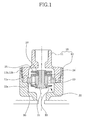
Figure 1 is a cross sectional view illustrating an example of the above
damping valve. As shown therein, there is provided a housing assembly 10 which
forms an outer shape of the damping valve. The housing assembly 10 is opened in
an upward direction, and the interior of the same is hollow. In particular, the
housing assembly 10 is divided into a first housing 11 and a second housing 12. A
male thread 11b and a female thread 12b are formed in an outer surface of the first
housing 11 and an inner surface of the second housing 12, respectively. Therefore,
the first housing 11 is threadedly inserted into the second housing 12 for thereby
implementing a thread coupling. In addition, a first jaw portion 11a and a second
jaw portion 12a each having an extended diameter are formed in the portions
opposite in an axial direction of the housings 11 and 12. A valve body 20 is
installed between the first jaw portion 11 a and the second jaw portion 12a. In
addition, a pin 21 passing through the valve body 20 is inserted into the center
portion of the valve body 20. The pin 21 is elastically suspended by dint of a spring
22 installed in an outer side of the lower portion. In addition, a plurality of flow path
holes 23 passing through the valve body 20 in the upward and downward
directions are formed in an outer surface of the valve body 20. A retainer 24 and a
washer 25 are installed in an outer side of the upper portion of the pin 21. A disk
27 which closely contacts with the upper side of the valve body by the spring
which downwardly elastically supports the pin 21 is installed in the lower side of
the washer 25. A valve 26 which closely contacts with a lower side of the valve
body 20 by the spring 22 is installed in a lower side of the pin 21. As a part of each
upper side and lower side of the valve body 20 which contacts with the disk 27 and
the valve 26, respectively, is spaced apart from the disk 27 and the valve 26, the
flow path holes 23 are always opened.
-
However, in the conventional damping valve, since there are provided the
first and second jaw portions 11a and 12a accurately processed in order for the
valve body 20 to be fixedly inserted into the separately formed first and second
housings 11 and 12, much inconvenience occurs in a fabrication of the same. In
addition, when assembling the valve body 20, since the first and second housings
11 and 12 having the first and second jaw portions 11 a and 12a are concurrently
assembled, the assembling process is so complicated, and much inconvenience is
caused.
the separately formed first housing 11 and second housing 12 form the first and
second jaw portions 11a and 12a which must be accurately processed in order for
the valve body 20 to be fixedly inserted into the first and second housings 11 and
12, respectively
SUMMARY OF THE INVENTION
-
Accordingly, it is an object of the present invention to provide a damping
valve of a steering system for a vehicle that overcomes the problems encountered
in the conventional art.
-
It is another object of the present invention to provide a damping valve of a
steering system for a vehicle which is capable of improving a coupling structure of
a housing of a damping valve and a valve body for thereby implementing an easier
fabrication and assembling operation.
-
In order to achieve the above objects, in a damping valve of a steering
apparatus which includes a housing assembly which is formed of a first housing
and a second housing threadedly engaged with the first housing and is fixedly
installed in one side of an oil pressure pipe, and a valve body which is installed in
the interior of the housing assembly, there is provided a damping valve of a
steering apparatus which comprises the first housing which includes an installation
jaw portion in which the valve body is inserted and mounted, and a cocking portion
which is adapted to fix the valve body inserted and mounted in the installation jaw
portion.
-
In particular, the cocking portion is preferably formed in an entrance
portion body of the installation jaw portion into which a valve is inserted.
BRIEF DESCRIPTION OF THE DRAWINGS
-
The present invention will become better understood with reference to the
accompanying drawings which are given only by way of illustration and thus are
not limitative of the present invention, wherein;
- Figure 1 is a cross sectional view illustrating a conventional damping valve;
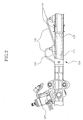
- Figure 2 is a front view illustrating a steering apparatus to which a damping
valve according to the present invention is adapted; and
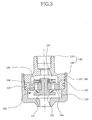
- Figure 3 is a cross sectional view illustrating a damping valve according to
the present invention.
-
DETAILED DESCRIPTION OF THE PREFERRED EMBODIMENTS
-
The preferred embodiments of the present invention will be described with
reference to the accompanying drawings.
-
Figure 2 is a front view illustrating a steering apparatus to which a
damping valve according to the present invention it adapted.
-
There are provided a rotary valve housing 117 to be crossed with a gear
box 110 at a side portion of a long hollow gear box 110 and a rotary valve 111
located in the rotary valve housing 117. One side of the rotary valve 111 is
connected with an oil pressure pump(not shown). In addition, a rack bar 112 is
installed in the interior of the gear box 110. A piston 113 which closely contacts
with an inner surface of the gear box 110 is installed in an intermediate portion of
the rack bar 112, so that a cylinder 114 is located in the left and right sides of the
piston 113. In addition, an oil pressure pipe 115 connected wit the rotary valve 111
is installed in an outer side of the cylinder 114. A damping valve 160 is installed in
one end side end of the oil pressure pipe 115. The damping valve 160 is capable
of adjusting the flow path in accordance with a flowing direction of a fluid which
flows between the rotary valve 111 and the cylinder 114 for thereby absorbing a
vibration transferred from the rack bar 112 installed in the cylinder 114 to the side
of a driver and a vibration of an oil pressure transferred to the rack bar 112, so that
it is possible to enhance a steering feeling.
-
Figure 3 is a view illustrating the damping valve. An outer shape of the
above damping valve is formed by the housing assembly 120 which is divided into
the first and second housings 130 and 140. In particular, since a male thread 131
and a female thread 141 are formed in an outer surface of the first housing 130
and an inner surface of the second housing 140,respectively, the male and female
threads 141 and 131 are engaged in a state that the first housing 130 is inserted
into the second housing 140. In addition, a valve body 150 is installed in the
interior of the first and second housings 130 and 140 for thereby directly
controlling a flow of the oil pressure. In addition, a pin 151 is installed in the center
portion of the valve body 150 in an upward and downward directions. The above
pin 151 is elastically suspended by the spring 152 installed in an outer lower
portion of the pin 151. A plurality of flow path holes 153 which pass through in an
upward and downward directions are formed in an outer portion of the valve body
150. A retainer 154 and a washer 155 are installed in an upper outer portion of the
pin 151. A disk 157 which is closely contacts with an upper portion of the valve
body 150 by dint of the spring 152 which elastically suspends the pin 151 is
installed in a lower portion of the washer 155. In addition, a valve 156 which
closely contacts with a lower side of the valve body 150 by dint of the spring 152 is
installed in a lower side of the pin 151. A part of each upper side and lower side of
the valve body 150 which contacts with the disk 157 and the valve 156,
respectively, always opens the flow path holes 153. The flow path holes 153 which
are always opened between the disk 157 and the valve 156 are formed in different
portions, so that a certain small amount of the fluid is always flown in the upward
and downward directions of the valve body 150 through the flow path holes 153.
Therefore, a certain oil pressure is stably transferred to the inner side of the valve.
-
In addition, the present invention is directed to improving a coupling
structure of the housing assembly 120 and the valve body 150 of the damping
valve for thereby implementing an easier fabrication and assembling operation. An
installation jaw portion 132 into which the valve body 150 is inserted and mounted
is formed in an inner surface of the first housing 130. A cocking portion 133 which
supports an end portion of the valve body 150 is formed in an entrance portion of
the installation jaw portion 132. In particular, the cocking portion 133 is extended
toward the center of the valve body 150. After the valve body 150 is inserted into
the installation jaw portion 132, the processing is performed toward the center side
of the valve body 150, for thereby preventing an escape of the valve body in an
axial direction.
-
The operation of the damping valve of the steering apparatus according to
the present invention will be described as follows.
-
When a larger oil pressure is applied from the upper side to the lower side,
the valve 156 which closes the flow path holes 153 of the lower side of the valve
body 150 pushes the spring 152 for thereby opening the flow path holes 153.
Therefore, the fluid flows through the flow path holes 153. Therefore, it is possible
to implement a smooth operation of the oil pressure without a certain resistance.
-
On the contrary, when a large oil pressure is applied from the lower side to
the upper side, the oil pressure may bend an outer side of the disk 157 of the
upper side of the valve body 150. Therefore, since a varying amount of the disk
157 is restricted by the washer 155 installed in the upper side, the moving amount
and moving speed of the fluid are decreased due to a large resistance and the
opening of the narrow flow path holes 153 for thereby implementing a desired
damping effect.
-
When assembling the damping valve, after the valve body 150 is installed
in the interior of the first housing 130, the cocking portion 133 is formed through
some processing. Therefore, the valve body 150 is fixed. In this state, the first and
second housings 130 and 140 are threadedly engaged.
-
As described above, in the damping valve of the steering apparatus
according to the present invention, since the installation jaw portion which needs
an accurate process in order for the valve body to be inserted and fixed is
provided in only the first housing, it is possible to implement an easier fabrication
of the damping valve.
-
In addition, since the valve body is easily first installed in the interior of the
first housing based on the cocking portion, when coupling the first and second
housings, it is possible to overcome the problems that the position of the valve
body is arranged. Therefore, it is possible to implement an easier assembling
operation of the damping valve.
-
As the present invention may be embodied in several forms without
departing from the spirit or essential characteristics thereof, it should also be
understood that the above-described examples are not limited by any of the details
of the foregoing description, unless otherwise specified, but rather should be
construed broadly within its spirit and scope as defined in the appended claims,
and therefore all changes and modifications that fall within the meets and bounds
of the claims, or equivalences of such meets and bounds are therefore intended to
be embraced by the appended claims.