EP1385779B2 - Pompe pour dosage precis et ses accessoires - Google Patents
Pompe pour dosage precis et ses accessoires Download PDFInfo
- Publication number
- EP1385779B2 EP1385779B2 EP02706431.0A EP02706431A EP1385779B2 EP 1385779 B2 EP1385779 B2 EP 1385779B2 EP 02706431 A EP02706431 A EP 02706431A EP 1385779 B2 EP1385779 B2 EP 1385779B2
- Authority
- EP
- European Patent Office
- Prior art keywords
- dose
- piston
- pump
- fluid
- control portion
- Prior art date
- Legal status (The legal status is an assumption and is not a legal conclusion. Google has not performed a legal analysis and makes no representation as to the accuracy of the status listed.)
- Expired - Lifetime
Links
Images


Classifications
-
- G—PHYSICS
- G01—MEASURING; TESTING
- G01F—MEASURING VOLUME, VOLUME FLOW, MASS FLOW OR LIQUID LEVEL; METERING BY VOLUME
- G01F11/00—Apparatus requiring external operation adapted at each repeated and identical operation to measure and separate a predetermined volume of fluid or fluent solid material from a supply or container, without regard to weight, and to deliver it
- G01F11/02—Apparatus requiring external operation adapted at each repeated and identical operation to measure and separate a predetermined volume of fluid or fluent solid material from a supply or container, without regard to weight, and to deliver it with measuring chambers which expand or contract during measurement
- G01F11/021—Apparatus requiring external operation adapted at each repeated and identical operation to measure and separate a predetermined volume of fluid or fluent solid material from a supply or container, without regard to weight, and to deliver it with measuring chambers which expand or contract during measurement of the piston type
- G01F11/025—Apparatus requiring external operation adapted at each repeated and identical operation to measure and separate a predetermined volume of fluid or fluent solid material from a supply or container, without regard to weight, and to deliver it with measuring chambers which expand or contract during measurement of the piston type with manually operated pistons
-
- A—HUMAN NECESSITIES
- A61—MEDICAL OR VETERINARY SCIENCE; HYGIENE
- A61F—FILTERS IMPLANTABLE INTO BLOOD VESSELS; PROSTHESES; DEVICES PROVIDING PATENCY TO, OR PREVENTING COLLAPSING OF, TUBULAR STRUCTURES OF THE BODY, e.g. STENTS; ORTHOPAEDIC, NURSING OR CONTRACEPTIVE DEVICES; FOMENTATION; TREATMENT OR PROTECTION OF EYES OR EARS; BANDAGES, DRESSINGS OR ABSORBENT PADS; FIRST-AID KITS
- A61F9/00—Methods or devices for treatment of the eyes; Devices for putting-in contact lenses; Devices to correct squinting; Apparatus to guide the blind; Protective devices for the eyes, carried on the body or in the hand
- A61F9/0008—Introducing ophthalmic products into the ocular cavity or retaining products therein
-
- B—PERFORMING OPERATIONS; TRANSPORTING
- B05—SPRAYING OR ATOMISING IN GENERAL; APPLYING FLUENT MATERIALS TO SURFACES, IN GENERAL
- B05B—SPRAYING APPARATUS; ATOMISING APPARATUS; NOZZLES
- B05B11/00—Single-unit hand-held apparatus in which flow of contents is produced by the muscular force of the operator at the moment of use
- B05B11/0005—Components or details
- B05B11/0037—Containers
- B05B11/0039—Containers associated with means for compensating the pressure difference between the ambient pressure and the pressure inside the container, e.g. pressure relief means
- B05B11/0044—Containers associated with means for compensating the pressure difference between the ambient pressure and the pressure inside the container, e.g. pressure relief means compensating underpressure by ingress of atmospheric air into the container, i.e. with venting means
-
- B—PERFORMING OPERATIONS; TRANSPORTING
- B05—SPRAYING OR ATOMISING IN GENERAL; APPLYING FLUENT MATERIALS TO SURFACES, IN GENERAL
- B05B—SPRAYING APPARATUS; ATOMISING APPARATUS; NOZZLES
- B05B11/00—Single-unit hand-held apparatus in which flow of contents is produced by the muscular force of the operator at the moment of use
- B05B11/01—Single-unit hand-held apparatus in which flow of contents is produced by the muscular force of the operator at the moment of use characterised by the means producing the flow
- B05B11/10—Pump arrangements for transferring the contents from the container to a pump chamber by a sucking effect and forcing the contents out through the dispensing nozzle
- B05B11/1001—Piston pumps
- B05B11/1009—Piston pumps actuated by a lever
- B05B11/1011—Piston pumps actuated by a lever without substantial movement of the nozzle in the direction of the pressure stroke
-
- B—PERFORMING OPERATIONS; TRANSPORTING
- B05—SPRAYING OR ATOMISING IN GENERAL; APPLYING FLUENT MATERIALS TO SURFACES, IN GENERAL
- B05B—SPRAYING APPARATUS; ATOMISING APPARATUS; NOZZLES
- B05B11/00—Single-unit hand-held apparatus in which flow of contents is produced by the muscular force of the operator at the moment of use
- B05B11/01—Single-unit hand-held apparatus in which flow of contents is produced by the muscular force of the operator at the moment of use characterised by the means producing the flow
- B05B11/10—Pump arrangements for transferring the contents from the container to a pump chamber by a sucking effect and forcing the contents out through the dispensing nozzle
- B05B11/1001—Piston pumps
- B05B11/1015—Piston pumps actuated without substantial movement of the nozzle in the direction of the pressure stroke
-
- B—PERFORMING OPERATIONS; TRANSPORTING
- B05—SPRAYING OR ATOMISING IN GENERAL; APPLYING FLUENT MATERIALS TO SURFACES, IN GENERAL
- B05B—SPRAYING APPARATUS; ATOMISING APPARATUS; NOZZLES
- B05B11/00—Single-unit hand-held apparatus in which flow of contents is produced by the muscular force of the operator at the moment of use
- B05B11/01—Single-unit hand-held apparatus in which flow of contents is produced by the muscular force of the operator at the moment of use characterised by the means producing the flow
- B05B11/10—Pump arrangements for transferring the contents from the container to a pump chamber by a sucking effect and forcing the contents out through the dispensing nozzle
- B05B11/1042—Components or details
- B05B11/1052—Actuation means
- B05B11/1056—Actuation means comprising rotatable or articulated levers
-
- B—PERFORMING OPERATIONS; TRANSPORTING
- B05—SPRAYING OR ATOMISING IN GENERAL; APPLYING FLUENT MATERIALS TO SURFACES, IN GENERAL
- B05B—SPRAYING APPARATUS; ATOMISING APPARATUS; NOZZLES
- B05B11/00—Single-unit hand-held apparatus in which flow of contents is produced by the muscular force of the operator at the moment of use
- B05B11/01—Single-unit hand-held apparatus in which flow of contents is produced by the muscular force of the operator at the moment of use characterised by the means producing the flow
- B05B11/10—Pump arrangements for transferring the contents from the container to a pump chamber by a sucking effect and forcing the contents out through the dispensing nozzle
- B05B11/1042—Components or details
- B05B11/1066—Pump inlet valves
- B05B11/107—Gate valves; Sliding valves
-
- B—PERFORMING OPERATIONS; TRANSPORTING
- B05—SPRAYING OR ATOMISING IN GENERAL; APPLYING FLUENT MATERIALS TO SURFACES, IN GENERAL
- B05B—SPRAYING APPARATUS; ATOMISING APPARATUS; NOZZLES
- B05B11/00—Single-unit hand-held apparatus in which flow of contents is produced by the muscular force of the operator at the moment of use
- B05B11/01—Single-unit hand-held apparatus in which flow of contents is produced by the muscular force of the operator at the moment of use characterised by the means producing the flow
- B05B11/10—Pump arrangements for transferring the contents from the container to a pump chamber by a sucking effect and forcing the contents out through the dispensing nozzle
- B05B11/1042—Components or details
- B05B11/1073—Springs
- B05B11/1074—Springs located outside pump chambers
-
- B—PERFORMING OPERATIONS; TRANSPORTING
- B05—SPRAYING OR ATOMISING IN GENERAL; APPLYING FLUENT MATERIALS TO SURFACES, IN GENERAL
- B05B—SPRAYING APPARATUS; ATOMISING APPARATUS; NOZZLES
- B05B11/00—Single-unit hand-held apparatus in which flow of contents is produced by the muscular force of the operator at the moment of use
- B05B11/01—Single-unit hand-held apparatus in which flow of contents is produced by the muscular force of the operator at the moment of use characterised by the means producing the flow
- B05B11/10—Pump arrangements for transferring the contents from the container to a pump chamber by a sucking effect and forcing the contents out through the dispensing nozzle
- B05B11/1042—Components or details
- B05B11/1073—Springs
- B05B11/1077—Springs characterised by a particular shape or material
-
- F—MECHANICAL ENGINEERING; LIGHTING; HEATING; WEAPONS; BLASTING
- F04—POSITIVE - DISPLACEMENT MACHINES FOR LIQUIDS; PUMPS FOR LIQUIDS OR ELASTIC FLUIDS
- F04B—POSITIVE-DISPLACEMENT MACHINES FOR LIQUIDS; PUMPS
- F04B9/00—Piston machines or pumps characterised by the driving or driven means to or from their working members
- F04B9/14—Pumps characterised by muscle-power operation
-
- B—PERFORMING OPERATIONS; TRANSPORTING
- B05—SPRAYING OR ATOMISING IN GENERAL; APPLYING FLUENT MATERIALS TO SURFACES, IN GENERAL
- B05B—SPRAYING APPARATUS; ATOMISING APPARATUS; NOZZLES
- B05B11/00—Single-unit hand-held apparatus in which flow of contents is produced by the muscular force of the operator at the moment of use
- B05B11/01—Single-unit hand-held apparatus in which flow of contents is produced by the muscular force of the operator at the moment of use characterised by the means producing the flow
- B05B11/10—Pump arrangements for transferring the contents from the container to a pump chamber by a sucking effect and forcing the contents out through the dispensing nozzle
- B05B11/1042—Components or details
- B05B11/1052—Actuation means
- B05B11/1056—Actuation means comprising rotatable or articulated levers
- B05B11/1057—Triggers, i.e. actuation means consisting of a single lever having one end rotating or pivoting around an axis or a hinge fixedly attached to the container, and another end directly actuated by the user
Definitions
- This invention relates to pumps, and, more particularly, to pumps having accurately-controlled dosing.
- pumps are used for various applications ranging from administration of health and beauty products (e.g., hand lotion) to lubricants.
- health and beauty products e.g., hand lotion
- lubricants e.g., hand lotion
- accurate volumetric control of a dose is not critical.
- Certain applications, however, have been developed which do require highly accurate dose control.
- pumps have been developed which deliver microdoses of ophthalmic fluid medication (5 microliter - 50 microliter), such as those disclosed in certain patents to some of the inventors herein: U.S. Patent No. 5,152,435, issued October 6, 1992 ; U.S. Patent No. 5,881,956, issued March 16, 1999 ; and, PCT Application No. PCT/US00/21206, filed August 23, 2000 .
- ophthalmic fluid medication 5 microliter - 50 microliter
- US Patent No. 5,816,455 discloses a frozen dessert dispensing apparatus, in which a draw valve must be retracted to allow the frozen dessert product to enter a metering cavity.
- various embodiments of a pump are provided having accurate control of a dose.
- the volume of the pump dosage can vary, although accurate control is particularly advantageous with microdosing.
- the invention provides a pump as claimed in claim 1.
- a simple design can be provided which has a limited number of critical dimensions controlling the dose amount.
- the volume of the fluid displaced from the dose-control portion of the fluid-collecting chamber controls or substantially controls the pump's dose.
- the dose-control portion is cylindrically shaped having two dimensions: a diameter and a length. As such, manufacturing variations affecting the dose amount may be minimized with only two dimensions being implicated (and their respective tolerances) in controlling dosing.
- the dose-control portion may encompass other volumetric shapes, such as a parallelepiped or a cylinder with a hemispherical end, although additional dimensions (and, thus, additional set(s) of tolerances) may be implicated (e.g., a parallelepiped includes a rectangular cross-section where parallelism between two sets of edges must be maintained; thus, squareness as a third factor must be considered).
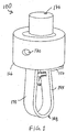
- the pump 100 includes a reservoir 112 and a fluid-collecting chamber 114, with the reservoir 112 being in communication, preferably open fluid communication, with the fluid-collecting chamber 114. As such, fluid accommodated within the reservoir 112 may be fed into the fluid-collecting chamber 114, preferably gravitationally.
- the term "chamber" refers to a volume which may be open, partially enclosed, or wholly enclosed.
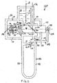
- the fluid-collecting chamber 114 defines a piston seat 116 having a dose-control portion 118 with a first cylindrical part 118a, having a length of X and a diameter of Y, and a second hemispherical part 118b, having a radius of R.
- the dose-control portion 118 may have other configurations.
- the dose-control portion 118 terminates in an end portion 120, and a discharge aperture 122 is defined therein. It is preferred that the discharge aperture 122 be located centrally within the end portion 120.
- a pump unit 124 is at least partially disposed within the fluid-collecting chamber 114.
- the pump unit 124 includes a piston 126 that is formed to seat within the piston seat 116; as shown in Figures 2-4 , the piston 126 is formed with a cylindrical body 128 and an end 130 which dimensionally correspond to the parts 118a and 118b of the dose-control portion 118.
- the piston 126 may have other configurations.
- the piston 126 is slidably disposed within a sleeve 132 that is defined in the body of the pump 100 and positioned to slide in and out of contact with the piston seat 116 defined by the fluid-collecting chamber 114.
- the sleeve 132 acts as a guide and support for the piston 126 in limiting sideward movement thereof.
- the piston 126 is spaced from the piston seat 116 and fluid F from the reservoir 112 floods the fluid-collecting chamber 114, acting under gravity (with the pump 100 being in an upright position).
- the piston 126 Upon actuation, as described below, the piston 126 is caused to slide forward into the piston seat 116. It is critical for pressure to build up in the fluid which is trapped between the piston 126 and the piston seat 116 during operation.
- the piston 126 acts to seal or substantially seal the dose-control portion 118 from other portions of the fluid-collecting chamber 114 upon sliding into the dose-control portion 118.
- the end 130 of the piston 126 may be formed with a diameter slightly greater than the dose-control portion 118 of the piston seat 116 to prevent fluid from by-passing the piston 126 and returning to the fluid-collecting chamber 114 during operation.
- the end 130 of the piston 126 may be formed with a diameter slightly smaller than the dose-control portion 118 of the piston seat 116, where the fluid has sufficient inherent viscosity to create a seal about the piston 126. If the fluid does not have sufficient inherent viscosity, the end 130 of the piston 126 may still be formed with a diameter slightly smaller than the dose-control portion 118 of the piston seat 116; here, the piston 126 would be considered to substantially seal the dose-control portion 118 from other portions of the fluid-collecting chamber 114, if the amount of any fluid leaking back into the fluid-collecting chamber 114 is taken into account in providing proper dosages.
- the body 128 may be formed with a smaller diameter than the end 130.
- the end 130 and/or the cylindrical body 128 may be formed with seal(s) (e.g., annular) for sealing the dose-control portion 118.
- the dose-control portion 118 is in fluid communication with a discharge chamber 134 via the discharge aperture 122 and a tapered throat 136 which diverges from the discharge aperture 122 towards the discharge chamber 134.
- a regulator 138 such as a discharge outlet check valve (which may be in the form of a ball as shown in the Figures) is biased against the tapered throat 136 in a rest position, as shown in Figure 2 .
- a coil spring 140 is used to generate the biasing force.
- a discharge nozzle 142 be formed to extend into the discharge chamber 134 having a cylindrical outer surface onto which the coil spring 140 is telescoped.
- An elongated slot 144 is defined in an end 146 of the discharge nozzle 142.
- the slot 144 is provided to ensure that the regulator 138 can never completely close off the entry into the discharge nozzle 142, thereby preventing the regulator 138 from throttling the outgoing fluid.
- the regulator 138 may be pressed against the end 146 with the slot 144 allowing the discharge nozzle 142 to communicate with the discharge chamber 134.
- the regulator 138 may be any valving element known to those skilled in the art which allows one-way flow, such as: a rubber diaphragm, or a spring-biased piston.
- the piston 126 is urged into the dose-control portion 118 thus sealing or substantially sealing the dose-control portion 118 from other portions of the fluid-collecting chamber 114 and allowing for a pressure rise in the fluid entrapped in the dose-control portion 118 (see Figure 3 ).
- the pressure of the fluid rises sufficiently to overcome the biasing force of the coil spring 140, and the regulator 138 yields to allow at least a portion of the entrapped fluid to exit the pump 100 via the slot 144 and the discharge nozzle 142.
- the pressure of the entrapped fluid decays and the regulator 138 is eventually urged into contact with the tapered throat 136.
- the regulator may operate in similar fashion to the outlet check valve disclosed in U.S. Patent No. 5,881,956 .
- the check valve 138 At rest, the check valve 138 is in pressing contact against the tapered throat 136 to prevent fluid from leaking out of the pump 100 due to the head of pressure from the reservoir 112.
- the piston 126 is returned to its rest position as explained below, and fluid re-charges the dose-control portion 118.
- a minimal number of tolerances can be utilized in controlling the dosing of the pump 100, thus, providing for accurate volumetric control of dosing.
- multiple dimensions are implicated in controlling dosing volume, with each dimension having its own set of manufacturing tolerance.
- the dimensions X, Y and R are implicated (assuming the piston 126 fully seats within the part 118b). Because the pumping action of the pump occurs with the movement of the piston 126 once the seal or substantial seal is formed, the volume of the displaced fluid is a function of the three dimensions X, Y and R.
- the volume of the dose administered by the pump 100 is controlled by the volume of fluid displaced by the piston 126 from the dose-control portion 118.
- the dose-control portion 118 and the piston 126 may have various cooperating configurations.
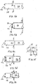
- the piston 126 and the dose-control portion 126 may be formed as right cylinders (i.e., with reference to the configuration of Figures 2-4 , the radius R would be infinite).
- Other matching cross-sectional shapes are possible, such as, polygonal, elliptical, or irregular.
- the dose-control portion 118 need not be straight and tubular, but may be frustoconical with the piston 126 matching.
- end 130 of the piston 126 may have various shapes, e.g., flat (as shown in Figure 5a ); convex (as shown in Figure 5c ); or, annular (as shown in Figure 5d cooperating with an annular or discontinuous ring 125). Furthermore, the end 130 need not match the corresponding contour of the dose-control portion 118 (e.g., Figure 5c ).
- the piston 126 need not slide throughout the full length of the dose-control portion 118. Rather, as shown in dashed lines, the piston 126 may have a limited extent of movement "t". The extent of movement can be limited by creating a stop limiting the stroke of the piston (e.g. a shoulder) and/or by mismatching the end 130 of the piston 126 and the end of the dose-control portion 118. With the subject invention, the volume of the administered dose is equal (or approximately equal) to the volume of the fluid displaced by the piston 126.
- the displaced volume will generally be the volume swept by the end 130 of the piston 126 during movement from the point of formation of the seal or substantial seal with the dose-control portion 118 to the full extent of movement of the piston 126 within the dose control-portion 118 (i.e., the volume swept over the distance "t"). In certain circumstances, it may be desired to displace a volume of fluid from the dose-control portion 118 that is greater than the pump's dose of fluid to compensate for losses, compressive effects, and/or fluid entrapment along its route to the nozzle.
- a critical element of the subject invention is the establishment of a seal or substantial seal with the dose-control portion 118.
- the seal may be formed at a location, or locations, spaced from the end 130 of the piston 126. Theoretically, the initial portion of the largest diameter section of the piston 126 entering the dose-control portion 118 will cause seal formation.
- the piston 126 of Figures 2-4 the piston 126 will theoretically seal the dose-control portion 118 upon the cylindrical body 128 initially entering the dose control portion 118. In practice, seal formation will generally occur past the theoretical point, due to dimensional differences, misalignment, fluid effects, friction, and so on.
- an enlarged piston region 127 spaced from the end 130 may be formed on the piston 126. The volume of fluid displaced by the enlarged position section 127 will be equal to (or approximately equal to) the volume of the dose.
- the piston 126 slides freely within the sleeve 132 and is sealed (seals not shown) to prevent any leakage of the fluid at this interface.
- the piston 126 is returned to its rest position (spaced away from the dose-control portion 118) after actuation.
- a spring handle 148 is utilized for returning the piston 126.
- free arm 150 of the spring handle 148 terminates at a split or forked ball end 152 (as shown in Figure 6 ), which engages with a reduced diameter portion 154 that extends from the piston 126. Any method known to those skilled in the art may be used to connect the free arm 150 to the piston 126.
- the free arm 150 is weakened at certain points 151 to allow it to articulate freely and be pivotable so that it can be used to drive the piston 126 in and out relative to the sleeve 132.
- the free arm 150 may be provided with other rotatable connections to replace the points 151 to allow relative rotation between the various portions of the free arm 150 (e.g., hinged connections).
- the free arm 150 is formed with memory to have a rest position as shown in Figure 2 .
- the spring handle 148 is operated by squeezing a handle 156 connected to the free arm 150. An operator may wrap their fingers about the handle 156 to engage a rear part 155 of the handle 156 with their fingers while their thumb bears against a fixed front end 157 of the handle 156.
- the pump 100 is held to the eye with the front of the thumb resting on the cheek.
- the squeezing action causes inward deflection of the rear part 155, as shown in Figure 4 , and corresponding inward movement of the free arm 150 and the piston 126 in actuating the pump 100, as described above.
- the free arm 150 returns to its rest position with the piston 126 returning to its rest position.
- Other modes of returning the piston 126 to its rest position may be used, including a separate return spring pressing against the piston 126.
- a latch 158 is provided to ensure sufficient momentum is imparted in actuating the pump 100, as disclosed in U.S. Patent No. 5,881,956 .
- the latch 158 employs two cantilever members 160 which are formed and disposed to engage a pair of shoulders 162 on a front member 164. As such, the latch 158 resists force applied to the spring handle 148. Upon further force being applied to the spring handle 148, the cantilever members 160 ultimately snap outwardly of the shoulders 162 (at a predetermined threshold force) giving a "kick" to the pump 100 (see Figures 3 and 4 ). The "kick" ensures that a whole dose of the fluid is delivered (not a partial dose) and that the dose is delivered with sufficient momentum.
- a locking collar 166 is provided which is rotatably mounted to the pump 100. Any manner known to those skilled in the art may be used to mount the locking collar 166 such as using beads 168.
- the locking collar 166 is formed with an opening 170 and with a tapered cut-out 172 ( Figure 7 ). When the pump 100 is not in use, the locking collar 166 is rotated (about axis 'A' shown in Figure 2 ) to bring the cut-out 172 into snap-on contact with channels 174 (which may be discontinuous or a single channel) formed towards the rear of the piston 126, as shown in Figure 2 .
- the cut-out 172 prevents sliding movement of the piston 126.
- the opening 170 in the locked position, is out of alignment with the discharge nozzle 142 to protect against the ingress of dirt thereinto ( Figure 2 ).
- the locking collar 166 rotates into a use position, as shown in Figures 3 and 4 , wherein the opening 170 aligns with the discharge nozzle 142 and the cut-out 172 does not engage the piston 126.
- vent slot 176 is set into the pump 100, (top view of slot 176 is shown in Figure 8 ).
- the vent slot 176 may be of various cross-sectional shapes, such as an ellipse,
- the reservoir 112 is preferably vented to atmosphere.
- a permanently opened vent slot 176 is set into the pump 100, (top view of slot 176 is shown in Figure 8 ).
- the vent slot 176 may be of various cross-sectional shapes, such as an ellipse, circle, polygon, or an irregular shape.
- the slot 176 also extends downwardly and about the piston 126.
- a cross vent 180 is defined in the piston 126 such that its ends are not in fluid communication with the vent slot 176 of the piston 126 at rest.
- the cross vent 180 is sealed from the reservoir 112 by the sleeve 132 with the piston 126 at rest.
- a first end 182 of the cross vent 180 comes into fluid communication with the vent slot 176 while a second end 184 of the cross vent is in fluid communication with the fluid-collecting chamber 114 (see Figures 3 and 4 ).
- the cross vent 180 only allows for venting to atmosphere when the piston 126 is urged towards the piston seat 116.
- Elements, described herein, are preferably formed of thermoplastic compatible with the fluid contents of the pump. Certain elements such as coil springs may be metallic, although may also be polymeric.
- ophthalmic fluids and fluid medications may be, and/or which may include, any of the following:
Landscapes
- Health & Medical Sciences (AREA)
- Engineering & Computer Science (AREA)
- Vascular Medicine (AREA)
- General Health & Medical Sciences (AREA)
- Ophthalmology & Optometry (AREA)
- Fluid Mechanics (AREA)
- Biomedical Technology (AREA)
- Heart & Thoracic Surgery (AREA)
- Physics & Mathematics (AREA)
- Life Sciences & Earth Sciences (AREA)
- Animal Behavior & Ethology (AREA)
- General Physics & Mathematics (AREA)
- Public Health (AREA)
- Veterinary Medicine (AREA)
- Mechanical Engineering (AREA)
- General Engineering & Computer Science (AREA)
- Infusion, Injection, And Reservoir Apparatuses (AREA)
- Containers And Packaging Bodies Having A Special Means To Remove Contents (AREA)
- Jet Pumps And Other Pumps (AREA)
Claims (18)
- Pompe de microdosage (100, 200) pour administrer des microdoses de fluide ophtalmique, à savoir des doses de 5 microlitres - 50 microlitres, ladite pompe comportant :un réservoir (112, 214) formé pour accepter au moins une des doses de fluide,une chambre de recueil de fluide (114, 216) en communication avec ledit réservoir, ladite chambre de recueil de fluide (114) définissant un siège de piston (116) comportant une partie de commande de dose (118), ladite partie de commande de dose se terminant dans une partie d'extrémité (120) qui définit une ouverture d'évacuation (122), et ladite partie de commande de dose (118) est en communication fluidique avec une chambre d'évacuation (134) par l'intermédiaire de l'ouverture d'évacuation (122) et une gorge conique (136) qui diverge depuis l'ouverture d'évacuation (122) vers la chambre d'évacuation (134) ;un piston (126, 218) disposé pour coulisser de manière réversible dans au moins une partie de commande de dose (118, 224) de ladite chambre de recueil de fluide,dans laquelle, lors de l'actionnement de la pompe, ledit piston étanchéifie ou étanchéifie sensiblement ladite partie de commande de dose par rapport à d'autres parties de ladite chambre de recueil de fluide, ledit piston coulissant dans ladite partie de commande de dose, et dans laquelle ledit piston est configuré pour déplacer un volume de fluide depuis ladite partie de commande de dose étanchéifiée ou sensiblement étanchéifiée, qui est approximativement égal ou supérieur au volume d'une des doses de fluide, etune buse (142, 226) qui est positionnée de telle sorte que du fluide déplacé par ledit piston depuis ladite partie de commande de dose est généralement poussé vers ladite buse,un régulateur (138) disposé entre ladite partie de commande de dose (118) et ladite buse (142) pour contrôler sélectivement un écoulement entre ceux-ci, ledit régulateur étant dans une position de repos, sollicité contre la gorge conique (136) qui diverge depuis l'ouverture d'évacuation (122), de sorte que le régulateur permet un écoulement unidirectionnel depuis la chambre de recueil de fluide (114), caractérisée en ce quelorsque la pompe (100, 200) est dans un état au repos, ledit piston (126, 218) n'étanchéifie pas ou n'étanchéifie sensiblement pas ladite partie de commande de dose (118, 224) par rapport à d'autres parties de ladite chambre de recueil de fluide (114, 216), de manière à permettre à ladite partie de commande de dose d'être rechargée en fluidedans laquelle, pendant l'actionnement, le piston (126) est poussé dans la partie de commande de dose (118) de façon à étanchéifier ou étanchéifier sensiblement la partie de commande de dose (118) par rapport aux autres parties de la chambre de recueil de fluide (114) et permettre une augmentation de pression dans le fluide piégé dans la partie de commande de dose (118),dans laquelle, lors d'un déplacement supplémentaire du piston (126) dans la partie de commande de dose (118), la pression du fluide augmente suffisamment pour compenser la force de sollicitation du régulateur, et le régulateur (138) cède de façon à laisser au moins une partie du fluide piégé s'échapper de la partie de commande (118) via l'ouverture d'évacuation (122), et ainsi quitter la pompe (100) et la buse d'évacuation (142), etdans laquelle la pompe comprend en outre une poignée à ressort ou un ressort de rappel agissant contre le piston ce qui, après l'actionnement, retourne le piston à sa position de repos.
- Pompe selon la revendication 1, dans laquelle ledit volume de ladite partie de commande de dose (118, 224) est défini par deux dimensions (100, 200).
- Pompe (100, 200) selon la revendication 2, dans laquelle une première desdites dimensions est une longueur axiale de ladite partie de commande de dose (118, 224).
- Pompe (100, 200) selon la revendication 3, dans laquelle une seconde desdites dimensions est un diamètre de ladite partie de commande de dose (118, 224).
- Pompe (100, 200) selon la revendication 2, dans laquelle ladite partie de commande de dose (118, 224) est définie uniquement par lesdites deux dimensions.
- Pompe (100, 200) selon la revendication 5, dans laquelle ladite partie de commande de dose (118, 224) a une forme cylindrique.
- Pompe (100, 200) selon la revendication 5, dans laquelle ladite partie de commande de dose (118, 224) a une forme tubulaire.
- Pompe (100, 200) selon la revendication 1, dans laquelle ledit régulateur (138) est un clapet antiretour.
- Pompe (100, 200) selon la revendication 8, dans laquelle ledit clapet antiretour est rappelé par ressort pour fermer une communication.
- Pompe (100, 200) selon la revendication 1, dans laquelle ledit réservoir (112, 214) est ventilé vers l'environnement ambiant.
- Pompe (100, 200) selon la revendication 11, comprenant en outre un passage de ventilation aveugle (180, 246), dans laquelle un alésage traversant est formé dans ledit piston (126, 218), ledit alésage traversant communiquant avec ledit passage de ventilation et ledit réservoir (112, 214) lorsque ledit piston coulisse avec une ampleur prédéterminée dans ladite partie de commande de dose (118, 224).
- Pompe (100, 200) selon la revendication 13, dans laquelle une partie dudit passage de sortie est définie dans ledit piston (126, 218).
- Pompe (100, 200) selon la revendication 1, dans laquelle ladite chambre de recueil de fluide (118, 224) est en communication de fluide ouverte avec ledit réservoir (112, 214).
- Pompe (100, 200) selon la revendication 1, dans laquelle du fluide provenant dudit réservoir est alimenté par gravité jusque dans ladite chambre de recueil de fluide (118, 224).
- Pompe (100, 200) selon la revendication 1, comprenant en outre une poignée (156, 210) reliée audit piston (126, 218) de telle sorte qu'une compression de ladite poignée provoque un déplacement dudit piston.
- Pompe (100, 200) selon la revendication 17, dans laquelle ladite poignée (156, 210) est rotative.
- Pompe (100, 200) selon la revendication 1, comprenant en outre un actionneur (150, 250) pouvant être mis en prise pour provoquer un déplacement dudit piston (126, 218) et un actionnement de ladite pompe (100, 200), ledit actionneur étant configuré pour être mis en prise à un emplacement espacé dudit piston pour provoquer un déplacement dudit piston.
- Pompe (100, 200) selon la revendication 1, dans laquelle toutes les parties dudit piston (126, 218) qui coulissent de manière réversible à travers ladite chambre de recueil de fluide (114, 216) sont contenues en continu dans ladite pompe (100, 200).
Applications Claiming Priority (3)
| Application Number | Priority Date | Filing Date | Title |
|---|---|---|---|
| US27033001P | 2001-02-21 | 2001-02-21 | |
| US270330P | 2001-02-21 | ||
| PCT/US2002/005864 WO2002068317A1 (fr) | 2001-02-21 | 2002-02-21 | Pompe pour dosage precis et ses accessoires |
Publications (4)
| Publication Number | Publication Date |
|---|---|
| EP1385779A1 EP1385779A1 (fr) | 2004-02-04 |
| EP1385779A4 EP1385779A4 (fr) | 2007-05-16 |
| EP1385779B1 EP1385779B1 (fr) | 2009-01-14 |
| EP1385779B2 true EP1385779B2 (fr) | 2020-06-24 |
Family
ID=23030879
Family Applications (1)
| Application Number | Title | Priority Date | Filing Date |
|---|---|---|---|
| EP02706431.0A Expired - Lifetime EP1385779B2 (fr) | 2001-02-21 | 2002-02-21 | Pompe pour dosage precis et ses accessoires |
Country Status (5)
| Country | Link |
|---|---|
| US (1) | US7261224B2 (fr) |
| EP (1) | EP1385779B2 (fr) |
| AT (1) | ATE420837T1 (fr) |
| DE (1) | DE60230863D1 (fr) |
| WO (1) | WO2002068317A1 (fr) |
Families Citing this family (10)
| Publication number | Priority date | Publication date | Assignee | Title |
|---|---|---|---|---|
| US6991137B2 (en) * | 2001-05-23 | 2006-01-31 | Ben Zane Cohen | Accurate dosing pump |
| DE60232805D1 (de) | 2001-09-20 | 2009-08-13 | Ben Z Cohen | Mikroabgabepumpe |
| GB0402698D0 (en) * | 2004-02-06 | 2004-03-10 | Glaxo Group Ltd | Delivery device |
| EP1709945A1 (fr) * | 2005-04-08 | 2006-10-11 | Helbling Technik Bern AG | Dispositif de distribution de liquide avec chambre de dosage et assemblage de soupape à tiroir |
| EP2262715B1 (fr) * | 2008-03-27 | 2011-10-19 | Vitop Moulding S.R.L. | Robinet destiné au dosage de liquides visqueux |
| US10154923B2 (en) | 2010-07-15 | 2018-12-18 | Eyenovia, Inc. | Drop generating device |
| WO2013138466A1 (fr) | 2012-03-13 | 2013-09-19 | Cohen, Ben, Z. | Buse |
| FR3001034A1 (fr) * | 2013-01-17 | 2014-07-18 | Picard Etancheite A | Verin de dosage volumetrique |
| JP2014207956A (ja) * | 2013-03-29 | 2014-11-06 | 株式会社ダイゾー | 洗浄用の吐出製品 |
| SG11201911895XA (en) | 2017-06-10 | 2020-01-30 | Eyenovia Inc | Methods and devices for handling a fluid and delivering the fluid to the eye |
Citations (7)
| Publication number | Priority date | Publication date | Assignee | Title |
|---|---|---|---|---|
| US4150146A (en) † | 1976-05-25 | 1979-04-17 | Gerhard Eisenbrand | Process for the preparation of unsymmetrically 1,3-disubstituted nitroso ureas |
| GB1579806A (en) † | 1977-09-16 | 1980-11-26 | Hedrich Vakuumanlagen Wilhelm | Metering pumps |
| US4623337A (en) † | 1984-03-08 | 1986-11-18 | Alpha Group, Inc. | Liquid dispensing apparatus |
| US4726747A (en) † | 1984-12-14 | 1988-02-23 | Ing. Erich Pfeiffer Gmbh & Co. Kg | Thrust piston pump for active substance dispenser |
| WO1992020460A1 (fr) † | 1991-05-03 | 1992-11-26 | Laurence Richard Penn | Ameliorations apportees ou relatives a un distributeur de liquides, et recipients utilises avec ledit distributeur |
| DE19610456A1 (de) † | 1996-03-16 | 1997-09-18 | Pfeiffer Erich Gmbh & Co Kg | Austragvorrichtung für Medien |
| DE10017438A1 (de) † | 2000-04-07 | 2001-10-11 | Otto Katz | Cremespender |
Family Cites Families (13)
| Publication number | Priority date | Publication date | Assignee | Title |
|---|---|---|---|---|
| US2781953A (en) * | 1953-03-13 | 1957-02-19 | Charles H Sylvander | Greasing ram device with plunger to boost pressure |
| US4995867A (en) * | 1990-01-24 | 1991-02-26 | Zollinger Eugene A | Aural medication dispenser |
| US5221194A (en) * | 1990-07-18 | 1993-06-22 | Nordson Corporation | Apparatus for electrostatically isolating and pumping conductive coating materials |
| US5190191A (en) * | 1991-03-13 | 1993-03-02 | Reyman Mark E | Apparatus for measured and unmeasured dispensing of viscous fluids |
| US5152435A (en) | 1991-06-13 | 1992-10-06 | Ben Zane Cohen | Ophthalmic dispensing pump |
| US5494194A (en) * | 1993-12-10 | 1996-02-27 | White Consolidated Industries, Inc. | Viscous material dispenser |
| US5464120A (en) * | 1994-05-27 | 1995-11-07 | Flurry International, Inc. | Method and apparatus for frozen dessert dispensing |
| FR2740118B1 (fr) * | 1995-10-23 | 1998-02-20 | Sofab | Distributeur de produits liquides ou pateux |
| US5881956A (en) | 1996-08-08 | 1999-03-16 | Ben Z. Cohen | Microdispensing ophthalmic pump |
| DE19636581C1 (de) * | 1996-09-09 | 1997-12-11 | Intec Bielenberg Gmbh & Co Kg | Wiederbefüllbarer Mehrwege-Container für hochviskose Medien |
| DE69733800T2 (de) * | 1996-12-24 | 2006-04-06 | Mixpac Systems Ag | Vorrichtung und Kartusche für einen umstülpbaren Schlauchbeutel |
| AU734817B2 (en) * | 1997-03-22 | 2001-06-21 | Mato Maschinen- Und Metallwarenfabrik Curt Matthaei Gmbh & Co Kg | Press for extruding lubricating grease |
| FR2764005B1 (fr) * | 1997-05-29 | 2004-12-10 | Sofab | Pompe a piston articule |
-
2002
- 2002-02-21 WO PCT/US2002/005864 patent/WO2002068317A1/fr not_active Application Discontinuation
- 2002-02-21 US US10/467,904 patent/US7261224B2/en not_active Expired - Lifetime
- 2002-02-21 AT AT02706431T patent/ATE420837T1/de not_active IP Right Cessation
- 2002-02-21 EP EP02706431.0A patent/EP1385779B2/fr not_active Expired - Lifetime
- 2002-02-21 DE DE60230863T patent/DE60230863D1/de not_active Expired - Lifetime
Patent Citations (7)
| Publication number | Priority date | Publication date | Assignee | Title |
|---|---|---|---|---|
| US4150146A (en) † | 1976-05-25 | 1979-04-17 | Gerhard Eisenbrand | Process for the preparation of unsymmetrically 1,3-disubstituted nitroso ureas |
| GB1579806A (en) † | 1977-09-16 | 1980-11-26 | Hedrich Vakuumanlagen Wilhelm | Metering pumps |
| US4623337A (en) † | 1984-03-08 | 1986-11-18 | Alpha Group, Inc. | Liquid dispensing apparatus |
| US4726747A (en) † | 1984-12-14 | 1988-02-23 | Ing. Erich Pfeiffer Gmbh & Co. Kg | Thrust piston pump for active substance dispenser |
| WO1992020460A1 (fr) † | 1991-05-03 | 1992-11-26 | Laurence Richard Penn | Ameliorations apportees ou relatives a un distributeur de liquides, et recipients utilises avec ledit distributeur |
| DE19610456A1 (de) † | 1996-03-16 | 1997-09-18 | Pfeiffer Erich Gmbh & Co Kg | Austragvorrichtung für Medien |
| DE10017438A1 (de) † | 2000-04-07 | 2001-10-11 | Otto Katz | Cremespender |
Also Published As
| Publication number | Publication date |
|---|---|
| EP1385779A4 (fr) | 2007-05-16 |
| EP1385779B1 (fr) | 2009-01-14 |
| EP1385779A1 (fr) | 2004-02-04 |
| ATE420837T1 (de) | 2009-01-15 |
| US20040129734A1 (en) | 2004-07-08 |
| WO2002068317A1 (fr) | 2002-09-06 |
| DE60230863D1 (de) | 2009-03-05 |
| US7261224B2 (en) | 2007-08-28 |
Similar Documents
| Publication | Publication Date | Title |
|---|---|---|
| EP1404609B1 (fr) | Pompe doseuse precise | |
| US20050165368A1 (en) | Delivery device and method of delivery | |
| CA1079237A (fr) | Distributeur mecanique comportant un dispositif permettant d'augmenter la pression de decharge et le temps de distribution | |
| US5217148A (en) | Pharmaceutical pump dispenser | |
| US7311227B2 (en) | Trigger sprayer venting system with reduced drag on vent piston | |
| EP1385779B2 (fr) | Pompe pour dosage precis et ses accessoires | |
| AU763918B2 (en) | Double spring precompression pump with priming feature | |
| CA2429810A1 (fr) | Pompe de dosage destinee a des distributeurs de liquide | |
| JPH03210075A (ja) | 半流動性物質用分与ヘッドの出口通路用シャッタ及びこのシャッタに好適に関連する分与ヘッド | |
| US4315582A (en) | Universal sequential dispensing pump system free of external check valves and having venting capability | |
| JPH0311235B2 (fr) | ||
| EP0749786B1 (fr) | Pompe de distributeur avec caractéristique d'amorçage | |
| JP2004511324A (ja) | 差動ピストンで形成される出口弁を有する投与部材 | |
| JP2002018330A (ja) | 吐出容器 | |
| JPH05192558A (ja) | ペーストまたは液体製品の調節および分配装置 | |
| KR20140146681A (ko) | 약제 디스펜서 | |
| BR112019007832B1 (pt) | Dispensador de bomba, bomba, e, acionador | |
| CN116547027A (zh) | 用于递送一定剂量的眼用液体的雾状物的装置、以及适用于用于递送眼用液体的雾状物的装置的泵 | |
| JPH02261468A (ja) | ピストンポンプ型分与装置 | |
| AU2002255601A1 (en) | Dosing pump for liquid dispensers | |
| AU2002235223A1 (en) | Dosing pump for liquid dispensers |
Legal Events
| Date | Code | Title | Description |
|---|---|---|---|
| PUAI | Public reference made under article 153(3) epc to a published international application that has entered the european phase |
Free format text: ORIGINAL CODE: 0009012 |
|
| 17P | Request for examination filed |
Effective date: 20030909 |
|
| AK | Designated contracting states |
Kind code of ref document: A1 Designated state(s): AT BE CH CY DE DK ES FI FR GB GR IE IT LI LU MC NL PT SE TR |
|
| AX | Request for extension of the european patent |
Extension state: AL LT LV MK RO SI |
|
| A4 | Supplementary search report drawn up and despatched |
Effective date: 20070418 |
|
| 17Q | First examination report despatched |
Effective date: 20070727 |
|
| GRAP | Despatch of communication of intention to grant a patent |
Free format text: ORIGINAL CODE: EPIDOSNIGR1 |
|
| GRAS | Grant fee paid |
Free format text: ORIGINAL CODE: EPIDOSNIGR3 |
|
| GRAA | (expected) grant |
Free format text: ORIGINAL CODE: 0009210 |
|
| AK | Designated contracting states |
Kind code of ref document: B1 Designated state(s): AT BE CH CY DE DK ES FI FR GB GR IE IT LI LU MC NL PT SE TR |
|
| REG | Reference to a national code |
Ref country code: GB Ref legal event code: FG4D |
|
| REG | Reference to a national code |
Ref country code: CH Ref legal event code: EP |
|
| REG | Reference to a national code |
Ref country code: IE Ref legal event code: FG4D |
|
| REF | Corresponds to: |
Ref document number: 60230863 Country of ref document: DE Date of ref document: 20090305 Kind code of ref document: P |
|
| PG25 | Lapsed in a contracting state [announced via postgrant information from national office to epo] |
Ref country code: NL Free format text: LAPSE BECAUSE OF FAILURE TO SUBMIT A TRANSLATION OF THE DESCRIPTION OR TO PAY THE FEE WITHIN THE PRESCRIBED TIME-LIMIT Effective date: 20090114 |
|
| NLV1 | Nl: lapsed or annulled due to failure to fulfill the requirements of art. 29p and 29m of the patents act | ||
| PG25 | Lapsed in a contracting state [announced via postgrant information from national office to epo] |
Ref country code: FI Free format text: LAPSE BECAUSE OF FAILURE TO SUBMIT A TRANSLATION OF THE DESCRIPTION OR TO PAY THE FEE WITHIN THE PRESCRIBED TIME-LIMIT Effective date: 20090114 Ref country code: ES Free format text: LAPSE BECAUSE OF FAILURE TO SUBMIT A TRANSLATION OF THE DESCRIPTION OR TO PAY THE FEE WITHIN THE PRESCRIBED TIME-LIMIT Effective date: 20090425 |
|
| PG25 | Lapsed in a contracting state [announced via postgrant information from national office to epo] |
Ref country code: SE Free format text: LAPSE BECAUSE OF FAILURE TO SUBMIT A TRANSLATION OF THE DESCRIPTION OR TO PAY THE FEE WITHIN THE PRESCRIBED TIME-LIMIT Effective date: 20090414 Ref country code: PT Free format text: LAPSE BECAUSE OF FAILURE TO SUBMIT A TRANSLATION OF THE DESCRIPTION OR TO PAY THE FEE WITHIN THE PRESCRIBED TIME-LIMIT Effective date: 20090615 Ref country code: AT Free format text: LAPSE BECAUSE OF FAILURE TO SUBMIT A TRANSLATION OF THE DESCRIPTION OR TO PAY THE FEE WITHIN THE PRESCRIBED TIME-LIMIT Effective date: 20090114 |
|
| PG25 | Lapsed in a contracting state [announced via postgrant information from national office to epo] |
Ref country code: MC Free format text: LAPSE BECAUSE OF NON-PAYMENT OF DUE FEES Effective date: 20090228 |
|
| REG | Reference to a national code |
Ref country code: CH Ref legal event code: PL |
|
| PLBI | Opposition filed |
Free format text: ORIGINAL CODE: 0009260 |
|
| PG25 | Lapsed in a contracting state [announced via postgrant information from national office to epo] |
Ref country code: LI Free format text: LAPSE BECAUSE OF NON-PAYMENT OF DUE FEES Effective date: 20090228 Ref country code: CH Free format text: LAPSE BECAUSE OF NON-PAYMENT OF DUE FEES Effective date: 20090228 Ref country code: DK Free format text: LAPSE BECAUSE OF FAILURE TO SUBMIT A TRANSLATION OF THE DESCRIPTION OR TO PAY THE FEE WITHIN THE PRESCRIBED TIME-LIMIT Effective date: 20090114 |
|
| PLAX | Notice of opposition and request to file observation + time limit sent |
Free format text: ORIGINAL CODE: EPIDOSNOBS2 |
|
| 26 | Opposition filed |
Opponent name: GLAXO GROUP LIMITED Effective date: 20091014 |
|
| REG | Reference to a national code |
Ref country code: IE Ref legal event code: MM4A |
|
| PG25 | Lapsed in a contracting state [announced via postgrant information from national office to epo] |
Ref country code: IE Free format text: LAPSE BECAUSE OF NON-PAYMENT OF DUE FEES Effective date: 20090221 |
|
| PLAF | Information modified related to communication of a notice of opposition and request to file observations + time limit |
Free format text: ORIGINAL CODE: EPIDOSCOBS2 |
|
| PLBB | Reply of patent proprietor to notice(s) of opposition received |
Free format text: ORIGINAL CODE: EPIDOSNOBS3 |
|
| PG25 | Lapsed in a contracting state [announced via postgrant information from national office to epo] |
Ref country code: GR Free format text: LAPSE BECAUSE OF FAILURE TO SUBMIT A TRANSLATION OF THE DESCRIPTION OR TO PAY THE FEE WITHIN THE PRESCRIBED TIME-LIMIT Effective date: 20090415 |
|
| PG25 | Lapsed in a contracting state [announced via postgrant information from national office to epo] |
Ref country code: IT Free format text: LAPSE BECAUSE OF FAILURE TO SUBMIT A TRANSLATION OF THE DESCRIPTION OR TO PAY THE FEE WITHIN THE PRESCRIBED TIME-LIMIT Effective date: 20090114 |
|
| PG25 | Lapsed in a contracting state [announced via postgrant information from national office to epo] |
Ref country code: LU Free format text: LAPSE BECAUSE OF NON-PAYMENT OF DUE FEES Effective date: 20090221 |
|
| PG25 | Lapsed in a contracting state [announced via postgrant information from national office to epo] |
Ref country code: TR Free format text: LAPSE BECAUSE OF FAILURE TO SUBMIT A TRANSLATION OF THE DESCRIPTION OR TO PAY THE FEE WITHIN THE PRESCRIBED TIME-LIMIT Effective date: 20090114 |
|
| PG25 | Lapsed in a contracting state [announced via postgrant information from national office to epo] |
Ref country code: CY Free format text: LAPSE BECAUSE OF FAILURE TO SUBMIT A TRANSLATION OF THE DESCRIPTION OR TO PAY THE FEE WITHIN THE PRESCRIBED TIME-LIMIT Effective date: 20090114 |
|
| RDAF | Communication despatched that patent is revoked |
Free format text: ORIGINAL CODE: EPIDOSNREV1 |
|
| APAH | Appeal reference modified |
Free format text: ORIGINAL CODE: EPIDOSCREFNO |
|
| APBM | Appeal reference recorded |
Free format text: ORIGINAL CODE: EPIDOSNREFNO |
|
| APBP | Date of receipt of notice of appeal recorded |
Free format text: ORIGINAL CODE: EPIDOSNNOA2O |
|
| REG | Reference to a national code |
Ref country code: FR Ref legal event code: PLFP Year of fee payment: 15 |
|
| APBQ | Date of receipt of statement of grounds of appeal recorded |
Free format text: ORIGINAL CODE: EPIDOSNNOA3O |
|
| APAH | Appeal reference modified |
Free format text: ORIGINAL CODE: EPIDOSCREFNO |
|
| APAJ | Date of receipt of notice of appeal modified |
Free format text: ORIGINAL CODE: EPIDOSCNOA2O |
|
| REG | Reference to a national code |
Ref country code: FR Ref legal event code: PLFP Year of fee payment: 16 |
|
| APBU | Appeal procedure closed |
Free format text: ORIGINAL CODE: EPIDOSNNOA9O |
|
| REG | Reference to a national code |
Ref country code: FR Ref legal event code: PLFP Year of fee payment: 17 |
|
| PLAY | Examination report in opposition despatched + time limit |
Free format text: ORIGINAL CODE: EPIDOSNORE2 |
|
| RIC2 | Information provided on ipc code assigned after grant |
Ipc: F04B 9/14 20060101ALI20190925BHEP Ipc: B05B 11/00 20060101AFI20190925BHEP Ipc: G01F 11/02 20060101ALI20190925BHEP Ipc: A61F 9/00 20060101ALI20190925BHEP |
|
| PUAH | Patent maintained in amended form |
Free format text: ORIGINAL CODE: 0009272 |
|
| STAA | Information on the status of an ep patent application or granted ep patent |
Free format text: STATUS: PATENT MAINTAINED AS AMENDED |
|
| 27A | Patent maintained in amended form |
Effective date: 20200624 |
|
| AK | Designated contracting states |
Kind code of ref document: B2 Designated state(s): AT BE CH CY DE DK ES FI FR GB GR IE IT LI LU MC NL PT SE TR |
|
| REG | Reference to a national code |
Ref country code: DE Ref legal event code: R102 Ref document number: 60230863 Country of ref document: DE |
|
| PGFP | Annual fee paid to national office [announced via postgrant information from national office to epo] |
Ref country code: FR Payment date: 20210222 Year of fee payment: 20 |
|
| PGFP | Annual fee paid to national office [announced via postgrant information from national office to epo] |
Ref country code: GB Payment date: 20210222 Year of fee payment: 20 Ref country code: BE Payment date: 20210224 Year of fee payment: 20 Ref country code: DE Payment date: 20210219 Year of fee payment: 20 |
|
| REG | Reference to a national code |
Ref country code: DE Ref legal event code: R071 Ref document number: 60230863 Country of ref document: DE |
|
| REG | Reference to a national code |
Ref country code: BE Ref legal event code: MK Effective date: 20220221 |
|
| REG | Reference to a national code |
Ref country code: GB Ref legal event code: PE20 Expiry date: 20220220 |
|
| PG25 | Lapsed in a contracting state [announced via postgrant information from national office to epo] |
Ref country code: GB Free format text: LAPSE BECAUSE OF EXPIRATION OF PROTECTION Effective date: 20220220 |