EP1385225B1 - Direkt-Alkohol-Brennstoffzelle und entsprechendes Herstellungsverfahren - Google Patents
Direkt-Alkohol-Brennstoffzelle und entsprechendes Herstellungsverfahren Download PDFInfo
- Publication number
- EP1385225B1 EP1385225B1 EP03013025A EP03013025A EP1385225B1 EP 1385225 B1 EP1385225 B1 EP 1385225B1 EP 03013025 A EP03013025 A EP 03013025A EP 03013025 A EP03013025 A EP 03013025A EP 1385225 B1 EP1385225 B1 EP 1385225B1
- Authority
- EP
- European Patent Office
- Prior art keywords
- fuel
- cell stack
- cell
- electrode
- flexible substrate
- Prior art date
- Legal status (The legal status is an assumption and is not a legal conclusion. Google has not performed a legal analysis and makes no representation as to the accuracy of the status listed.)
- Expired - Lifetime
Links
Images
Classifications
-
- H—ELECTRICITY
- H01—ELECTRIC ELEMENTS
- H01M—PROCESSES OR MEANS, e.g. BATTERIES, FOR THE DIRECT CONVERSION OF CHEMICAL ENERGY INTO ELECTRICAL ENERGY
- H01M8/00—Fuel cells; Manufacture thereof
- H01M8/02—Details
- H01M8/0202—Collectors; Separators, e.g. bipolar separators; Interconnectors
-
- H—ELECTRICITY
- H01—ELECTRIC ELEMENTS
- H01M—PROCESSES OR MEANS, e.g. BATTERIES, FOR THE DIRECT CONVERSION OF CHEMICAL ENERGY INTO ELECTRICAL ENERGY
- H01M4/00—Electrodes
- H01M4/86—Inert electrodes with catalytic activity, e.g. for fuel cells
- H01M4/96—Carbon-based electrodes
-
- H—ELECTRICITY
- H01—ELECTRIC ELEMENTS
- H01M—PROCESSES OR MEANS, e.g. BATTERIES, FOR THE DIRECT CONVERSION OF CHEMICAL ENERGY INTO ELECTRICAL ENERGY
- H01M8/00—Fuel cells; Manufacture thereof
- H01M8/10—Fuel cells with solid electrolytes
- H01M8/1016—Fuel cells with solid electrolytes characterised by the electrolyte material
- H01M8/1018—Polymeric electrolyte materials
- H01M8/102—Polymeric electrolyte materials characterised by the chemical structure of the main chain of the ion-conducting polymer
- H01M8/1023—Polymeric electrolyte materials characterised by the chemical structure of the main chain of the ion-conducting polymer having only carbon, e.g. polyarylenes, polystyrenes or polybutadiene-styrenes
-
- H—ELECTRICITY
- H01—ELECTRIC ELEMENTS
- H01M—PROCESSES OR MEANS, e.g. BATTERIES, FOR THE DIRECT CONVERSION OF CHEMICAL ENERGY INTO ELECTRICAL ENERGY
- H01M8/00—Fuel cells; Manufacture thereof
- H01M8/10—Fuel cells with solid electrolytes
- H01M8/1016—Fuel cells with solid electrolytes characterised by the electrolyte material
- H01M8/1018—Polymeric electrolyte materials
- H01M8/1039—Polymeric electrolyte materials halogenated, e.g. sulfonated polyvinylidene fluorides
-
- H—ELECTRICITY
- H01—ELECTRIC ELEMENTS
- H01M—PROCESSES OR MEANS, e.g. BATTERIES, FOR THE DIRECT CONVERSION OF CHEMICAL ENERGY INTO ELECTRICAL ENERGY
- H01M8/00—Fuel cells; Manufacture thereof
- H01M8/10—Fuel cells with solid electrolytes
- H01M8/1016—Fuel cells with solid electrolytes characterised by the electrolyte material
- H01M8/1018—Polymeric electrolyte materials
- H01M8/1041—Polymer electrolyte composites, mixtures or blends
- H01M8/1046—Mixtures of at least one polymer and at least one additive
- H01M8/1051—Non-ion-conducting additives, e.g. stabilisers, SiO2 or ZrO2
-
- H—ELECTRICITY
- H01—ELECTRIC ELEMENTS
- H01M—PROCESSES OR MEANS, e.g. BATTERIES, FOR THE DIRECT CONVERSION OF CHEMICAL ENERGY INTO ELECTRICAL ENERGY
- H01M16/00—Structural combinations of different types of electrochemical generators
- H01M16/003—Structural combinations of different types of electrochemical generators of fuel cells with other electrochemical devices, e.g. capacitors, electrolysers
-
- H—ELECTRICITY
- H01—ELECTRIC ELEMENTS
- H01M—PROCESSES OR MEANS, e.g. BATTERIES, FOR THE DIRECT CONVERSION OF CHEMICAL ENERGY INTO ELECTRICAL ENERGY
- H01M2300/00—Electrolytes
- H01M2300/0017—Non-aqueous electrolytes
- H01M2300/0065—Solid electrolytes
- H01M2300/0082—Organic polymers
-
- H—ELECTRICITY
- H01—ELECTRIC ELEMENTS
- H01M—PROCESSES OR MEANS, e.g. BATTERIES, FOR THE DIRECT CONVERSION OF CHEMICAL ENERGY INTO ELECTRICAL ENERGY
- H01M2300/00—Electrolytes
- H01M2300/0088—Composites
- H01M2300/0091—Composites in the form of mixtures
-
- H—ELECTRICITY
- H01—ELECTRIC ELEMENTS
- H01M—PROCESSES OR MEANS, e.g. BATTERIES, FOR THE DIRECT CONVERSION OF CHEMICAL ENERGY INTO ELECTRICAL ENERGY
- H01M4/00—Electrodes
- H01M4/86—Inert electrodes with catalytic activity, e.g. for fuel cells
- H01M4/90—Selection of catalytic material
- H01M4/92—Metals of platinum group
-
- H—ELECTRICITY
- H01—ELECTRIC ELEMENTS
- H01M—PROCESSES OR MEANS, e.g. BATTERIES, FOR THE DIRECT CONVERSION OF CHEMICAL ENERGY INTO ELECTRICAL ENERGY
- H01M8/00—Fuel cells; Manufacture thereof
- H01M8/02—Details
- H01M8/0202—Collectors; Separators, e.g. bipolar separators; Interconnectors
- H01M8/0204—Non-porous and characterised by the material
- H01M8/0206—Metals or alloys
-
- H—ELECTRICITY
- H01—ELECTRIC ELEMENTS
- H01M—PROCESSES OR MEANS, e.g. BATTERIES, FOR THE DIRECT CONVERSION OF CHEMICAL ENERGY INTO ELECTRICAL ENERGY
- H01M8/00—Fuel cells; Manufacture thereof
- H01M8/04—Auxiliary arrangements, e.g. for control of pressure or for circulation of fluids
- H01M8/04082—Arrangements for control of reactant parameters, e.g. pressure or concentration
- H01M8/04089—Arrangements for control of reactant parameters, e.g. pressure or concentration of gaseous reactants
- H01M8/04119—Arrangements for control of reactant parameters, e.g. pressure or concentration of gaseous reactants with simultaneous supply or evacuation of electrolyte; Humidifying or dehumidifying
- H01M8/04156—Arrangements for control of reactant parameters, e.g. pressure or concentration of gaseous reactants with simultaneous supply or evacuation of electrolyte; Humidifying or dehumidifying with product water removal
-
- Y—GENERAL TAGGING OF NEW TECHNOLOGICAL DEVELOPMENTS; GENERAL TAGGING OF CROSS-SECTIONAL TECHNOLOGIES SPANNING OVER SEVERAL SECTIONS OF THE IPC; TECHNICAL SUBJECTS COVERED BY FORMER USPC CROSS-REFERENCE ART COLLECTIONS [XRACs] AND DIGESTS
- Y02—TECHNOLOGIES OR APPLICATIONS FOR MITIGATION OR ADAPTATION AGAINST CLIMATE CHANGE
- Y02E—REDUCTION OF GREENHOUSE GAS [GHG] EMISSIONS, RELATED TO ENERGY GENERATION, TRANSMISSION OR DISTRIBUTION
- Y02E60/00—Enabling technologies; Technologies with a potential or indirect contribution to GHG emissions mitigation
- Y02E60/30—Hydrogen technology
- Y02E60/50—Fuel cells
-
- Y—GENERAL TAGGING OF NEW TECHNOLOGICAL DEVELOPMENTS; GENERAL TAGGING OF CROSS-SECTIONAL TECHNOLOGIES SPANNING OVER SEVERAL SECTIONS OF THE IPC; TECHNICAL SUBJECTS COVERED BY FORMER USPC CROSS-REFERENCE ART COLLECTIONS [XRACs] AND DIGESTS
- Y02—TECHNOLOGIES OR APPLICATIONS FOR MITIGATION OR ADAPTATION AGAINST CLIMATE CHANGE
- Y02P—CLIMATE CHANGE MITIGATION TECHNOLOGIES IN THE PRODUCTION OR PROCESSING OF GOODS
- Y02P70/00—Climate change mitigation technologies in the production process for final industrial or consumer products
- Y02P70/50—Manufacturing or production processes characterised by the final manufactured product
Definitions
- the present invention relates to a direct-alcohol fuel-cell stack.
- Fuel cells are electrochemical devices capable of converting the chemical energy contained in a fuel into electrical direct current, in the absence of moving parts.
- Said electrochemical device comprises an anode and a cathode separated by an electrolyte, i.e., a substance that enables migration of the ions.
- an electrolyte i.e., a substance that enables migration of the ions.
- catalysts for example platinum.
- the cell is supplied with the fuel (typically hydrogen or another molecule containing hydrogen) and with an oxidant (typically oxygen or air), which, electrochemically combined, generate electricity and produce water as waste product.
- the fuel typically hydrogen or another molecule containing hydrogen
- an oxidant typically oxygen or air
- the individual cells characterized by voltages comprised between half a volt and one volt according to the technology adopted, can be connected in series, so as to obtain a total voltage of the desired value.
- Said arrangement of the cells forms the so-called fuel-cell stack, to which there can be associated an inverter and a transformer for converting the direct current generated by the stack of cells into alternating current at the desired voltage and at the desired frequency.
- an electrochemical solid electrolyte cell system is known, based on a flat, gas-permeable, non-conductive flexible polymer substrate.
- the cell regions consist of a porous, electrically-conductive, flexible electrode layer, a proton conducting, flexible membrane layer and a second porous, flexible, electron-conducting electrode layer, the various layers being laid one over the other, using coating technologies.
- the purpose of the present invention is to provide a newly conceived fuel cell stack, of particularly advantageous use from the cost point of view and/or from the functional point of view for the purposes of production of fuel-cell stack usable as independent systems for the production of energy.
- a fuel cell is a system consisting of two electrodes (an anode and a cathode), between which is set an electrolyte, usually in the form of a membrane, which directly converts chemical energy into electrical energy, without combustion or moving parts, by means of the electrochemical combination of hydrogen and oxygen, producing water, electricity and heat.
- Methanol has proven one of the best candidates as fuel for fuel cells, on account of its ease of storage and transportation and its low cost.
- the use of methanol in liquid form enables a considerable reduction of the complexity of the fuel cells, enabling their application in various sectors.
- DMFCs direct-methanol fuel cells
- the fuel can be supplied in the absence of preliminary reforming, i.e., a treatment to which fuels rich in hydrocarbons must, instead, be subjected for converting them into hydrogen.
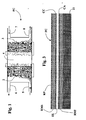
- Figure 1 is a schematic representation of the typical structure of a fuel cell which uses methanol in aqueous solution (CH 3 OH + H 2 O) as source of hydrogen.
- FC designates the cell as a whole, which comprises an anode 2 and a cathode 3, between which is set a suitable membrane 4, which has the function of electrolyte.
- the electrodes 2 and 3 can each be formed by applying on the opposite faces of the membrane 4 a thin catalytic layer, consisting of granules of carbon activated with noble metals and carrying PTFE or TeflonTM, for impermeabilization of some pores.
- a thin catalytic layer consisting of granules of carbon activated with noble metals and carrying PTFE or TeflonTM, for impermeabilization of some pores.
- the cell FC moreover envisages two bipolar plates that are located on both sides of the membrane 4 and are provided for enabling passage of electrical current and for yielding heat to the external environment.
- the reference numbers 5 and 6 designate, respectively, an inlet of the fuel in a chamber of the anode 2 and an outlet from said chamber for the carbon dioxide produced by the electrochemical reaction.
- the numbers 7 and 8 designate, respectively, an inlet for air into a chamber of the cathode 3 and an outlet from said chamber for the water produced by the electrochemical reaction.
- the alcohol laps the anode 2, whilst the oxidant laps the cathode 3.
- the catalytic layer of the anode 2 stimulates the electro-oxidation of the molecules of alcohol, which separate into positive ions and electrons. Whilst the electrons pass from the anode 2 to the cathode 3 through the electrical load, the protons migrate from the anode 2 to the cathode 3 through the membrane 4 and, once they have reached the cathode 3, combine with the oxygen in the air and with the electrons that come from the anode 2, to form water.
- the water-methanol mixture is sent directly to the anode 2, by means of the inlet 5, where it reacts, releasing CO 2 , H + ions, and electrons.
- the air is, instead, carried to the cathode 3, the O 2 of which reacts with the H + ions diffused through the membrane 4 and with the electrons, to be reduced to H 2 O.
- the cell reactions at the anode 2 and at the cathode 3 are, respectively, the following: CH 3 OH + H 2 O ⁇ 6e- + 6H + + CO 2 3/2O 2 + 6e - + 6H + ⁇ 3H 2 O which, combined, yield the overall reaction: CH 3 OH + 3/2O 2 ⁇ 2H 2 O + CO 2
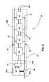
- Figure 2 is a schematic representation of a miniaturized direct-alcohol fuel-cell stack according to the invention, designated as a whole by 20.
- the fuel-cell stack 20 has a control portion 20A and a portion for generation of energy 20B.
- the portion 20B comprises a flexible support designated by 21, which in the case exemplified is in the form of a film made of polymeric material.
- a material usable for the fabrication of the supporting film 21 is Kapton ® , a light, insulating, polyamide material, which presents excellent resistance to heat, good thermal conductivity and is non-absorbent.
- FC miniaturized direct-methanol fuel cells
- the reference number 24 designates a duct for supply of the methanol-based fuel, from which there branch off the inlets 22.
- the number 25 designates a duct for discharge of the water generated by the cells FC, from which there branch off the outlets 23.
- the fuel-distribution system, formed by the duct 24 and by the inlets 22, and the water-discharge system, formed by the duct 25 and by the inlets 23, can be obtained by hot-pressing of a polymeric layer on the supporting film 21.
- the reference number 26 designates conducting paths that connect the cells FC in series to one another; said connections can be obtained by means of deposition of electrically conductive material on the supporting film 21.
- the control module 20A comprises a micro-pump 30, preferably of a piezoelectric type and made using MEMS (Micro Electro-Mechanical Systems) technology, which has the function of regulating the supply of fuel to the various cells FC.
- the micro-pump 30 comprises a respective inlet branch 30A, for connection to the source of methanol in aqueous solution, and a delivery branch 30B, provided for being hydraulically connected, with modalities in themselves known, to the duct 24 of the portion 20B.
- the micro-pump 30 has also the important function of maintaining the cell FC moist, when this is not in use, with the aim of preventing the deterioration of its electrode-electrolyte structure.
- the micro-pump 30 is controlled by a microprocessor designated by MP, which likewise controls a supercapacitor, designated by 31.
- the supercapacitor 31 is of a conception in itself known and consequently will not be described herein; here it will suffice to recall that a supercapacitor is an electronic device, obtainable using nanotechnologies, which is capable of accumulating static electricity and supplying electrical energy and is made up of two polarizable electrodes, a separator, and an electrolyte, where the electric field is stored in the interfaces between the electrolyte and the electrodes.
- the supercapacitor 31 is provided for being electrically connected, with modalities in themselves known, to the paths 26 at input to the first cell FC of the portion 20B. Its function is that of compensating the time of response of the electrochemical system and activating the electrical load supplied by the fuel-cell stack 20 before this can achieve the maximum electrical output to the output 26A of the paths 26.
- the first cell FC of the portion 20B of the fuel-cell stack functions then as charger of the supercapacitor 31, when the electrical load does not absorb current.
- a further function of the supercapacitor 31 is that of supplying the microprocessor MP, and thus also the micro-pump 30.
- FIG. 3 shows the multi-layer structure of an individual miniaturized cell FC provided according to the invention, which can be obtained with various procedures.
- the flexible supporting film 21 there are defined the paths 26, by means of deposition of electrically conductive material.
- the supporting film 21 is then provided with the fuel-distribution system 22, 24 and the water-discharge system 23, 25, for example by means of hot-pressing of a polymeric layer on the film itself.
- an electrode-electrolyte assembled structure which comprises:
- the electrode-electrolyte structure could be obtained by depositing the anodic catalyst CA on the layer RMI.
- the electrolyte EL On the anodic catalyst CA there will then be positioned or deposited the electrolyte EL. This will be followed, in order, by deposition of the cathodic catalyst CA, of the layer of metallic coating RMS, and of the possible protective layer RP.
- Another possibility is that of obtaining separately the complex formed by the layers RMI, CA, EL, CC, RMS, then to proceed to its fixing (for example, by gluing) on the flexible supporting film 21.
- the electrodes or catalysts CA, CC may comprise granules of carbon and a noble metal, such as for example platinum, palladium, rhodium, iridium, osmium or ruthenium, and the electrolyte EL can be in the form of a membrane of Nafion.
- a noble metal such as for example platinum, palladium, rhodium, iridium, osmium or ruthenium
- the electrolyte EL can be in the form of a membrane of Nafion.
- the electrolyte EL may thus advantageously be in the form of a composite Nafion-zeolite membrane, in order to enable reduction of the crossover of methanol.
- the catalysts CA, CC can comprise fullerenes and/or carbon nanotubes and/or carbon nanofibres.
- the said structure is thus configured as a continuous ribbon having a thickness of some millimetres, which can be rolled up. From said ribbon it will be possible to cut a piece designed to form the portion 20B illustrated in Figure 2 , comprising a desired number of cells FC according to the total voltage that it is intended to reach. To this piece there will evidently be combined the respective control portion 20A.
- micromachining for obtaining multiple layers that form the components of the cells FC on the flexible substrate made from the film 21 enables, according to the invention, production of low-cost fuel-cell stacks with high production volumes.
Landscapes
- Chemical & Material Sciences (AREA)
- General Chemical & Material Sciences (AREA)
- Electrochemistry (AREA)
- Chemical Kinetics & Catalysis (AREA)
- Sustainable Energy (AREA)
- Life Sciences & Earth Sciences (AREA)
- Sustainable Development (AREA)
- Manufacturing & Machinery (AREA)
- Engineering & Computer Science (AREA)
- Crystallography & Structural Chemistry (AREA)
- Composite Materials (AREA)
- Fuel Cell (AREA)
- Inert Electrodes (AREA)
- Confectionery (AREA)
- Investigating Or Analysing Materials By Optical Means (AREA)
- Fats And Perfumes (AREA)
Claims (26)
- Brennstoffzellenstapel (20), umfassend eine Vielzahl von Direkt-Alkohol-Brennstoffzellen (FC), wobei jede Zelle (FC) eine Struktur aufweist, umfassend:- eine erste Elektrode (CA);- eine zweite Elektrode (CC);- einen Elektrolyten (EL), angeordnet zwischen der ersten Elektrode (CA) und der zweiten Elektrode (CC);- Mittel (RMI, RMS) um elektrischen Strom zu der ersten Elektrode (CA) und der zweiten Elektrode (CC) zu leiten,wobei- die Struktur miniaturisiert ist und aus einer Vielzahl von Schichten besteht, die aufeinander angeordnet sind, und- die Strukturen der Zelle dieser Vielzahl in einer unbeweglichen bzw. nicht entfernbaren Weise mit einem gleichen flexiblen Substrat (21) verbunden sind,dadurch gekennzeichnet, dass des weiteren auf eine nicht entfernbaren Weise mit dem flexiblen Substrat (21) verbunden sind:- ein Brennstoffeinlass (22) für jede Zelle (FC) des ersten Stapels, wobei sich die Brennstoffeinlässe (22) von einem ersten Kanal (24) für den Brennstoff verzweigen, wobei der erste Kanal (24) auch auf eine nicht entfernbare Weise mit dem flexiblen Substrat (21) verbunden ist, und- einen Wasserauslass (23) für jede Zelle (FC) des Stapels, wobei sich die Wasserauslässe (23) von einem zweiten Kanal (25) für Wasser, welches durch die chemische Zellreaktion erzeugt wird, verzweigen, wobei der zweite Kanal (25) auch auf eine nicht entfernbare Weise mit dem flexiblen Substrat (21) verbunden ist.
- Brennstoffzellenstapel nach Anspruch 1, dadurch gekennzeichnet, dass der erste Kanal (22) mit den Brennstoffeinlässen (22) und der zweite Kanal (25) mit den Wasserauslässen (23) von einer polymeren Schicht gebildet werden, welche auf dem flexiblen Substrat (21) heiß gepresst ist.
- Brennstoffzellenstapel nach Anspruch 1, dadurch gekennzeichnet, dass das flexible Substrat (21) aus einem polymeren Material besteht, insbesondere aus Kapton®.
- Brennstoffzellenstapel nach Anspruch 1, dadurch gekennzeichnet, dass auch leitfähige Bahnen (26) auf dem flexiblen Substrat (21) auf eine nicht entfernbare Weise angeordnet sind, welche die Reihe der Zellen dieser Vielzahl elektrisch verbinden.
- Brennstoffzellenstapel nach Anspruch 1, dadurch gekennzeichnet, dass die Mittel zum Leiten des elektrischen Stromes (RMI, RMS) umfassen:- eine erste Schicht aus metallischem Material (RMI), welche auf dem flexiblen Substrat (21) angeordnet ist, wobei die erste Elektrode einen anodischen Katalysator (CA) umfasst, welcher sich in Kontakt mit der ersten Schicht (RMI) befindet, und- eine zweite Schicht aus metallischen Material (RMS) ), welche auf dem Elektrolyt (EL) angeordnet ist, wobei die zweite Elektrode einen kathodischen Katalysator (CC) umfasst, welcher sich in Kontakt mit der zweiten Schicht (RMS) befindet.
- Brennstoffzellenstapel nach Anspruch 5, dadurch gekennzeichnet, dass sich auf der zweiten Schicht (RMS) eine Schutzschicht (RP) befindet, insbesondere bestehend aus polymerem Material.
- Brennstoffzellenstapel nach Anspruch 1, dadurch gekennzeichnet, dass der Elektrolyt (EL) in der Form einer Membran vorliegt, insbesondere bestehend aus Nafion.
- Brennstoffzellenstapel nach Anspruch 1, dadurch gekennzeichnet, dass der Elektrolyt (EL) eine Verbundstruktur aufweist, umfassend Nafion und Zeolith.
- Brennstoffzellenstapel nach Anspruch 1, dadurch gekennzeichnet, dass die Mittel zum Leiten des elektrischen Stromes zu der ersten Elektrode und der zweiten Elektrode in der Form von metallischen Schichten (RMI, RMS) vorliegen.
- Brennstoffzellenstapel nach Anspruch 1, dadurch gekennzeichnet, dass wenigstens eine der ersten Elektrode und der zweiten Elektrode einen Katalysator (CA, CC) umfasst, enthaltend Granulate aus Kohlenstoff und einem Edelmetall, gewählt aus den Gruppen bestehend aus Platin, Palladium, Rhodium, Iridium, Osmium und Ruthenium.
- Brennstoffzellenstapel nach Anspruch 1, dadurch gekennzeichnet, dass wenigstens eine der ersten Elektrode und der zweiten Elektrode einen Katalysator umfassen (CA, CC), enthaltend ein Material gewählt aus der Gruppe bestehend aus Fullerenen, Kohlenstoffnanoröhren, Kohlenstoffnanofasern.
- Brennstoffzellenstapel nach Anspruch 1, dadurch gekennzeichnet, dass wenigstens eine der ersten Elektrode und der zweiten Elektrode einen Katalysator (CA, CC) umfasst, welcher auf Zeolith-Material abgeschieden ist.
- Brennstoffzellenstapel nach Anspruch 1, dadurch gekennzeichnet, dass er ein erstes Steuerteil (20A) und ein zweites energieerzeugenden Teil (20B) umfasst, wobei der erste Teil eine Mikropumpe (30) aufweist, welche betreibbar ist, um die Zuführung des Brennstoffes zu den Zellen (FC) zu regulieren, wobei die Mikropumpe (30) umfasst:- einen jeweiligen Einfüllstutzen (30A), um mit einer Quelle des Brennstoffs verbunden zu werden; und- eine Abgabestutzen (30B), um mit der ersten Leitung (24) verbunden zu werden.
- Brennstoffzellenstapel nach Anspruch 13, dadurch gekennzeichnet, dass die Mikropumpe eine piezoelektrische Pumpe ist, welche die MEMS (Micro Electro Mechanical Systems) Technologie verwendet.
- Brennstoffzellenstapel nach Anspruch 13, dadurch gekennzeichnet, dass die Mikropumpe (30) betreibbar ist, um die Zellen (FC) der Vielzahl feucht zu halten, um die Zerstörung der miniaturisierten Struktur dieser zu verhindern.
- Brennstoffzellenstapel nach Anspruch 13, dadurch gekennzeichnet, dass der erste Teil (20A) einen Mikrocontroller (MP) zur Steuerung der Mikropumpe (30) umfasst.
- Brennstoffzellenstapel nach Anspruch 13, dadurch gekennzeichnet, dass der erste Teil (20A) einen Superkondensator (31) umfasst, bereitgestellt zur elektrischen Verbindung mit einer Zelle (FC) der Vielzahl.
- Brennstoffzellenstapel nach Anspruch 16 und 17, dadurch gekennzeichnet, dass der Superkondensator betreibbar ist, um den Mikrocontroller (MP) zu versorgen.
- Brennstoffzellenstapel nach Anspruch 13, dadurch gekennzeichnet, dass der zweite Teil (20B) das flexible Substrat (21) umfasst, mit der jeweiligen Vielzahl von Zellen (FC) und Teile der ersten und zweiten Kanäle (24, 25) und das der erste Teil (20A) von dem flexiblen Substrat (21) abliegt und bereitgestellt ist, um elektrisch mit einer Zelle (FC) des zweiten Teils (20B) verbunden zu werden und hydraulisch mit der ersten Leitung (24) des zweiten Teils (20B).
- Brennstoffzellenstapel nach Anspruch 1, dadurch gekennzeichnet, dass das flexible Substrat (21) in der Form eines Bandes vorliegt, welches sich in der Länge entwickelt und geeignet ist, aufgerollt zu werden.
- Brennstoffzellenstapel nach Anspruch 1, dadurch gekennzeichnet, dass die Zellen (FC) geeignet sind, um mit Methanol in wässriger Lösung versorgt zu werden.
- Verfahren zur Herstellung eines Brennstoffzellenstapels (20) umfassend eine Vielzahl von Direkt-Alkohol-Brennstoffzellen gemäß einem oder mehreren der Ansprüche 1 bis 21, umfassend die Schritte:i) Erhalten eines flexiblen Substrats (21) in der Form eines Bandes, welches sich in der Länge entwickelt; undii) Aufbringen auf das flexible Substrat (21) auf eine nicht entfernbare Weise, einer Vielzahl von diesen miniaturisierten Strukturen, bestehend aus einer Vielzahl von Schichten, welche aufeinander gestapelt sind, wobei die Schichten mittels Mikrobearbeitung erhalten werden;
dadurch gekennzeichnet, dass es auch die Schritte umfasst:iii) Aufbringen auf eine nicht-entfernbare Weise auf das flexible Substrat (21):- einen Brennstoffeinlass (22) für jede Zelle (FC) des Stapels, wobei die Brennstoffeinlässe (22) von einem ersten Kanal (24) für den Brennstoff verzweigen, wobei der erste Kanal (24) auch auf eine nicht entfernbare Weise mit dem flexiblen Substrat (21) verbunden ist, und- einen Wasserauslass (23) für jede Zelle (FC) des Stapels, wobei die Wasserauslässe (23) von einem zweiten Kanal (25) für Wasser, welches durch die chemische Zellreaktion erzeugt wird, verzweigen, wobei der zweite Kanal (25) auch auf eine nicht entfernbare Weise mit dem flexiblen Substrat (21) verbunden ist,iv) Schneiden des flexiblen Substrats (21) um ein Stück (20B) zu erhalten, umfassend eine gewünschte Zahl der Zellen (FC) und umfassend einen jeweiligen Anteil der ersten und zweiten Leitungen (24, 25),v) elektrisches Verbinden einer Zelle (FC) des Stücks (20B) und hydraulisches Verbinden des ersten Kanals (24) mit einer Steuereinrichtung (20A), wobei der Aufbau aus dem Stück (20B) und der Steuereinrichtung (20A) den Brennstoffzellenstapel (20) bildet. - Verfahren nach Anspruch 22, dadurch gekennzeichnet, dass der Schritt iii) das Heißpressen einer polymeren Schicht auf das flexible Substrat (21) umfasst.
- Verfahren nach Anspruch 22, dadurch gekennzeichnet, dass der Schritt ii) das Verbinden des flexiblen Substrats (21) mit leitfähigen Bahnen (26) umfasst, die die Zellen dieses Stückes (20B) elektrisch in Reihe verbinden.
- Verfahren nach Anspruch 23, dadurch gekennzeichnet, dass der Schritt v) das hydraulische Verbinden eines eine Pumpe (30) bildenden Teils der Steuereinrichtung (20A) mit der ersten Leitung (24) umfasst.
- Verfahren nach Anspruch 24, dadurch gekennzeichnet, dass der Schritt v) das elektrische Verbinden eines einen Superkondensator (30) bildenden Teils der Steuereinrichtung (20A) mit den leitfähigen Wegen (26) einer Zelle (FC) des Stücks (20B) umfasst.
Applications Claiming Priority (2)
| Application Number | Priority Date | Filing Date | Title |
|---|---|---|---|
| IT2002TO000643A ITTO20020643A1 (it) | 2002-07-23 | 2002-07-23 | Pila a combustibile ad alcool diretto e relativo metodo di realizzazione |
| ITTO20020643 | 2002-07-23 |
Publications (3)
| Publication Number | Publication Date |
|---|---|
| EP1385225A2 EP1385225A2 (de) | 2004-01-28 |
| EP1385225A3 EP1385225A3 (de) | 2006-02-01 |
| EP1385225B1 true EP1385225B1 (de) | 2008-05-21 |
Family
ID=11459519
Family Applications (1)
| Application Number | Title | Priority Date | Filing Date |
|---|---|---|---|
| EP03013025A Expired - Lifetime EP1385225B1 (de) | 2002-07-23 | 2003-06-10 | Direkt-Alkohol-Brennstoffzelle und entsprechendes Herstellungsverfahren |
Country Status (6)
| Country | Link |
|---|---|
| US (1) | US7442460B2 (de) |
| EP (1) | EP1385225B1 (de) |
| JP (1) | JP2004055550A (de) |
| AT (1) | ATE396511T1 (de) |
| DE (1) | DE60321094D1 (de) |
| IT (1) | ITTO20020643A1 (de) |
Families Citing this family (12)
| Publication number | Priority date | Publication date | Assignee | Title |
|---|---|---|---|---|
| US6723299B1 (en) | 2001-05-17 | 2004-04-20 | Zyvex Corporation | System and method for manipulating nanotubes |
| US6905667B1 (en) | 2002-05-02 | 2005-06-14 | Zyvex Corporation | Polymer and method for using the polymer for noncovalently functionalizing nanotubes |
| US20040034177A1 (en) | 2002-05-02 | 2004-02-19 | Jian Chen | Polymer and method for using the polymer for solubilizing nanotubes |
| KR100827861B1 (ko) * | 2003-05-22 | 2008-05-07 | 지벡스 퍼포먼스 머티리얼즈, 엘엘씨 | 나노복합물 및 이의 제조 방법 |
| JP5254608B2 (ja) * | 2004-04-13 | 2013-08-07 | ザイベックス パフォーマンス マテリアルズ、インク. | モジュール式ポリ(フェニレンエチレニン)の合成方法及びナノマテリアルを機能化するためにその電子特性を微調整する方法 |
| US7296576B2 (en) * | 2004-08-18 | 2007-11-20 | Zyvex Performance Materials, Llc | Polymers for enhanced solubility of nanomaterials, compositions and methods therefor |
| JP4765307B2 (ja) * | 2004-12-10 | 2011-09-07 | パナソニック株式会社 | 燃料電池システム |
| DE102005015660B4 (de) * | 2005-04-06 | 2013-03-28 | Forschungszentrum Jülich GmbH | Niedertemperatur-Brennstoffzellenstapel sowie Verfahren zum Betreiben desselben |
| US8033501B2 (en) * | 2005-06-10 | 2011-10-11 | The Boeing Company | Method and apparatus for attaching electrically powered seat track cover to through hole seat track design |
| US20090263698A1 (en) * | 2005-10-20 | 2009-10-22 | Nec Corporation | Fuel cell system and fuel cell |
| US9227895B2 (en) * | 2007-07-09 | 2016-01-05 | Albemarle Corporation | Methods and apparatus for producing alcohols from syngas |
| EP2173694B1 (de) * | 2007-07-09 | 2016-11-23 | Albemarle Corporation | Verfahren zur herstellung von alkoholen aus synthesegas |
Family Cites Families (8)
| Publication number | Priority date | Publication date | Assignee | Title |
|---|---|---|---|---|
| WO1997001194A1 (de) * | 1995-06-21 | 1997-01-09 | Fraunhofer-Gesellschaft zur Förderung der angewandten Forschung e.V. | Elektrochemisches festelektrolyt-zellsystem |
| US6299744B1 (en) * | 1997-09-10 | 2001-10-09 | California Institute Of Technology | Hydrogen generation by electrolysis of aqueous organic solutions |
| CA2370899A1 (en) * | 1999-05-06 | 2000-11-16 | Sandia Corporation | Fuel cell and membrane |
| US6503654B2 (en) * | 1999-05-19 | 2003-01-07 | George A. Marchetti | Thin graphite bipolar plate with associated gaskets and carbon cloth flow-field for use in an ionomer membrane fuel cell |
| TW434927B (en) * | 1999-11-03 | 2001-05-16 | Ind Tech Res Inst | Method for fabricating metal-air battery and its structure |
| US6541149B1 (en) * | 2000-02-29 | 2003-04-01 | Lucent Technologies Inc. | Article comprising micro fuel cell |
| WO2002013295A1 (en) * | 2000-08-08 | 2002-02-14 | Sony Corporation | Proton-conductive electrode, process for producing the same, and electrochemical device |
| US6620542B2 (en) * | 2001-05-30 | 2003-09-16 | Hewlett-Packard Development Company, L.P. | Flex based fuel cell |
-
2002
- 2002-07-23 IT IT2002TO000643A patent/ITTO20020643A1/it unknown
-
2003
- 2003-06-10 EP EP03013025A patent/EP1385225B1/de not_active Expired - Lifetime
- 2003-06-10 AT AT03013025T patent/ATE396511T1/de not_active IP Right Cessation
- 2003-06-10 DE DE60321094T patent/DE60321094D1/de not_active Expired - Lifetime
- 2003-07-02 JP JP2003190386A patent/JP2004055550A/ja active Pending
- 2003-07-23 US US10/624,608 patent/US7442460B2/en not_active Expired - Fee Related
Also Published As
| Publication number | Publication date |
|---|---|
| US20040018423A1 (en) | 2004-01-29 |
| ATE396511T1 (de) | 2008-06-15 |
| EP1385225A3 (de) | 2006-02-01 |
| JP2004055550A (ja) | 2004-02-19 |
| ITTO20020643A0 (it) | 2002-07-23 |
| EP1385225A2 (de) | 2004-01-28 |
| ITTO20020643A1 (it) | 2004-01-23 |
| DE60321094D1 (de) | 2008-07-03 |
| US7442460B2 (en) | 2008-10-28 |
Similar Documents
| Publication | Publication Date | Title |
|---|---|---|
| US7807317B2 (en) | Anode electrodes for direct oxidation fuel cells and systems operating with concentrated liquid fuel | |
| EP1366533B1 (de) | Brennstoffzellenanordnung | |
| US20020076598A1 (en) | Direct methanol fuel cell including integrated flow field and method of fabrication | |
| US20030157396A1 (en) | Modified diffusion layer for use in a fuel cell system | |
| NL1021701C2 (nl) | PEM-brandstofcel. | |
| KR20030076559A (ko) | 직접 메탄올 연료 전지 시스템 | |
| EP1385225B1 (de) | Direkt-Alkohol-Brennstoffzelle und entsprechendes Herstellungsverfahren | |
| WO2005082024A2 (en) | Fuel cell apparatus and method of fabrication | |
| US6794071B2 (en) | Apparatus and method for rapidly increasing power output from a direct oxidation fuel cell | |
| KR20110094082A (ko) | 연료 전지 | |
| EP2287955A2 (de) | Verfahren zur herstellung einer polymerelektrolytmembran für eine brennstoffzelle, membranelektrodenbaugruppe und brennstoffzelle des polymerelektrolytmembrantyps | |
| US20100068592A1 (en) | Electrodes for use in hydrocarbon-based membrane electrode assemblies of direct oxidation fuel cells | |
| CN118202085A (zh) | 生产过氧化氢的设备和方法 | |
| US8227137B2 (en) | Polymer membrane for fuel cell and method of preparing the same | |
| US8133633B2 (en) | Structure of cathode electrode for fuel cell | |
| US20050164059A1 (en) | Local vapor fuel cell | |
| CN100334767C (zh) | 液体燃料供给型燃料电池 | |
| WO2009119434A1 (ja) | 燃料電池ユニット、燃料電池スタックおよび電子機器 | |
| JP2005141994A (ja) | 高分子電解質型燃料電池 | |
| US20070003801A1 (en) | Fuel cell | |
| JP3946228B2 (ja) | 燃料電池 | |
| KR20250082014A (ko) | 일체형 재생 연료전지 및 이를 적용한 스택 | |
| CN121079805A (zh) | 燃料电池 | |
| KR20110124947A (ko) | 플렉서블 연료전지 | |
| KR20050122452A (ko) | 연료 전지용 바이폴라 플레이트, 이의 제조 방법 및 이를포함하는 연료 전지 |
Legal Events
| Date | Code | Title | Description |
|---|---|---|---|
| PUAI | Public reference made under article 153(3) epc to a published international application that has entered the european phase |
Free format text: ORIGINAL CODE: 0009012 |
|
| AK | Designated contracting states |
Kind code of ref document: A2 Designated state(s): AT BE BG CH CY CZ DE DK EE ES FI FR GB GR HU IE IT LI LU MC NL PT RO SE SI SK TR |
|
| AX | Request for extension of the european patent |
Extension state: AL LT LV MK |
|
| PUAL | Search report despatched |
Free format text: ORIGINAL CODE: 0009013 |
|
| AK | Designated contracting states |
Kind code of ref document: A3 Designated state(s): AT BE BG CH CY CZ DE DK EE ES FI FR GB GR HU IE IT LI LU MC NL PT RO SE SI SK TR |
|
| AX | Request for extension of the european patent |
Extension state: AL LT LV MK |
|
| 17P | Request for examination filed |
Effective date: 20060403 |
|
| 17Q | First examination report despatched |
Effective date: 20060905 |
|
| AKX | Designation fees paid |
Designated state(s): AT BE BG CH CY CZ DE DK EE ES FI FR GB GR HU IE IT LI LU MC NL PT RO SE SI SK TR |
|
| GRAP | Despatch of communication of intention to grant a patent |
Free format text: ORIGINAL CODE: EPIDOSNIGR1 |
|
| GRAS | Grant fee paid |
Free format text: ORIGINAL CODE: EPIDOSNIGR3 |
|
| GRAA | (expected) grant |
Free format text: ORIGINAL CODE: 0009210 |
|
| AK | Designated contracting states |
Kind code of ref document: B1 Designated state(s): AT BE BG CH CY CZ DE DK EE ES FI FR GB GR HU IE IT LI LU MC NL PT RO SE SI SK TR |
|
| REG | Reference to a national code |
Ref country code: GB Ref legal event code: FG4D |
|
| REG | Reference to a national code |
Ref country code: CH Ref legal event code: EP |
|
| REF | Corresponds to: |
Ref document number: 60321094 Country of ref document: DE Date of ref document: 20080703 Kind code of ref document: P |
|
| REG | Reference to a national code |
Ref country code: IE Ref legal event code: FG4D |
|
| PG25 | Lapsed in a contracting state [announced via postgrant information from national office to epo] |
Ref country code: SI Free format text: LAPSE BECAUSE OF FAILURE TO SUBMIT A TRANSLATION OF THE DESCRIPTION OR TO PAY THE FEE WITHIN THE PRESCRIBED TIME-LIMIT Effective date: 20080521 |
|
| PG25 | Lapsed in a contracting state [announced via postgrant information from national office to epo] |
Ref country code: FI Free format text: LAPSE BECAUSE OF FAILURE TO SUBMIT A TRANSLATION OF THE DESCRIPTION OR TO PAY THE FEE WITHIN THE PRESCRIBED TIME-LIMIT Effective date: 20080521 Ref country code: ES Free format text: LAPSE BECAUSE OF FAILURE TO SUBMIT A TRANSLATION OF THE DESCRIPTION OR TO PAY THE FEE WITHIN THE PRESCRIBED TIME-LIMIT Effective date: 20080901 |
|
| NLV1 | Nl: lapsed or annulled due to failure to fulfill the requirements of art. 29p and 29m of the patents act | ||
| PG25 | Lapsed in a contracting state [announced via postgrant information from national office to epo] |
Ref country code: AT Free format text: LAPSE BECAUSE OF FAILURE TO SUBMIT A TRANSLATION OF THE DESCRIPTION OR TO PAY THE FEE WITHIN THE PRESCRIBED TIME-LIMIT Effective date: 20080521 Ref country code: NL Free format text: LAPSE BECAUSE OF FAILURE TO SUBMIT A TRANSLATION OF THE DESCRIPTION OR TO PAY THE FEE WITHIN THE PRESCRIBED TIME-LIMIT Effective date: 20080521 |
|
| PG25 | Lapsed in a contracting state [announced via postgrant information from national office to epo] |
Ref country code: CZ Free format text: LAPSE BECAUSE OF FAILURE TO SUBMIT A TRANSLATION OF THE DESCRIPTION OR TO PAY THE FEE WITHIN THE PRESCRIBED TIME-LIMIT Effective date: 20080521 Ref country code: MC Free format text: LAPSE BECAUSE OF NON-PAYMENT OF DUE FEES Effective date: 20080630 Ref country code: SE Free format text: LAPSE BECAUSE OF FAILURE TO SUBMIT A TRANSLATION OF THE DESCRIPTION OR TO PAY THE FEE WITHIN THE PRESCRIBED TIME-LIMIT Effective date: 20080821 Ref country code: DK Free format text: LAPSE BECAUSE OF FAILURE TO SUBMIT A TRANSLATION OF THE DESCRIPTION OR TO PAY THE FEE WITHIN THE PRESCRIBED TIME-LIMIT Effective date: 20080521 Ref country code: PT Free format text: LAPSE BECAUSE OF FAILURE TO SUBMIT A TRANSLATION OF THE DESCRIPTION OR TO PAY THE FEE WITHIN THE PRESCRIBED TIME-LIMIT Effective date: 20081021 |
|
| REG | Reference to a national code |
Ref country code: CH Ref legal event code: PL |
|
| PG25 | Lapsed in a contracting state [announced via postgrant information from national office to epo] |
Ref country code: RO Free format text: LAPSE BECAUSE OF FAILURE TO SUBMIT A TRANSLATION OF THE DESCRIPTION OR TO PAY THE FEE WITHIN THE PRESCRIBED TIME-LIMIT Effective date: 20080521 Ref country code: SK Free format text: LAPSE BECAUSE OF FAILURE TO SUBMIT A TRANSLATION OF THE DESCRIPTION OR TO PAY THE FEE WITHIN THE PRESCRIBED TIME-LIMIT Effective date: 20080521 Ref country code: BE Free format text: LAPSE BECAUSE OF FAILURE TO SUBMIT A TRANSLATION OF THE DESCRIPTION OR TO PAY THE FEE WITHIN THE PRESCRIBED TIME-LIMIT Effective date: 20080521 |
|
| PLBE | No opposition filed within time limit |
Free format text: ORIGINAL CODE: 0009261 |
|
| STAA | Information on the status of an ep patent application or granted ep patent |
Free format text: STATUS: NO OPPOSITION FILED WITHIN TIME LIMIT |
|
| 26N | No opposition filed |
Effective date: 20090224 |
|
| GBPC | Gb: european patent ceased through non-payment of renewal fee |
Effective date: 20080821 |
|
| PG25 | Lapsed in a contracting state [announced via postgrant information from national office to epo] |
Ref country code: BG Free format text: LAPSE BECAUSE OF FAILURE TO SUBMIT A TRANSLATION OF THE DESCRIPTION OR TO PAY THE FEE WITHIN THE PRESCRIBED TIME-LIMIT Effective date: 20080821 Ref country code: IE Free format text: LAPSE BECAUSE OF NON-PAYMENT OF DUE FEES Effective date: 20080610 Ref country code: EE Free format text: LAPSE BECAUSE OF FAILURE TO SUBMIT A TRANSLATION OF THE DESCRIPTION OR TO PAY THE FEE WITHIN THE PRESCRIBED TIME-LIMIT Effective date: 20080521 |
|
| PG25 | Lapsed in a contracting state [announced via postgrant information from national office to epo] |
Ref country code: LI Free format text: LAPSE BECAUSE OF NON-PAYMENT OF DUE FEES Effective date: 20080630 Ref country code: CH Free format text: LAPSE BECAUSE OF NON-PAYMENT OF DUE FEES Effective date: 20080630 |
|
| PG25 | Lapsed in a contracting state [announced via postgrant information from national office to epo] |
Ref country code: GB Free format text: LAPSE BECAUSE OF NON-PAYMENT OF DUE FEES Effective date: 20080821 |
|
| PG25 | Lapsed in a contracting state [announced via postgrant information from national office to epo] |
Ref country code: HU Free format text: LAPSE BECAUSE OF FAILURE TO SUBMIT A TRANSLATION OF THE DESCRIPTION OR TO PAY THE FEE WITHIN THE PRESCRIBED TIME-LIMIT Effective date: 20081122 Ref country code: CY Free format text: LAPSE BECAUSE OF FAILURE TO SUBMIT A TRANSLATION OF THE DESCRIPTION OR TO PAY THE FEE WITHIN THE PRESCRIBED TIME-LIMIT Effective date: 20080521 Ref country code: LU Free format text: LAPSE BECAUSE OF NON-PAYMENT OF DUE FEES Effective date: 20080610 |
|
| PG25 | Lapsed in a contracting state [announced via postgrant information from national office to epo] |
Ref country code: TR Free format text: LAPSE BECAUSE OF FAILURE TO SUBMIT A TRANSLATION OF THE DESCRIPTION OR TO PAY THE FEE WITHIN THE PRESCRIBED TIME-LIMIT Effective date: 20080521 |
|
| PG25 | Lapsed in a contracting state [announced via postgrant information from national office to epo] |
Ref country code: GR Free format text: LAPSE BECAUSE OF FAILURE TO SUBMIT A TRANSLATION OF THE DESCRIPTION OR TO PAY THE FEE WITHIN THE PRESCRIBED TIME-LIMIT Effective date: 20080822 |
|
| PG25 | Lapsed in a contracting state [announced via postgrant information from national office to epo] |
Ref country code: IT Free format text: LAPSE BECAUSE OF NON-PAYMENT OF DUE FEES Effective date: 20090610 |
|
| PGRI | Patent reinstated in contracting state [announced from national office to epo] |
Ref country code: IT Effective date: 20110616 |
|
| PGFP | Annual fee paid to national office [announced via postgrant information from national office to epo] |
Ref country code: DE Payment date: 20120607 Year of fee payment: 10 |
|
| PGFP | Annual fee paid to national office [announced via postgrant information from national office to epo] |
Ref country code: FR Payment date: 20120619 Year of fee payment: 10 |
|
| PGFP | Annual fee paid to national office [announced via postgrant information from national office to epo] |
Ref country code: IT Payment date: 20120604 Year of fee payment: 10 |
|
| REG | Reference to a national code |
Ref country code: FR Ref legal event code: ST Effective date: 20140228 |
|
| REG | Reference to a national code |
Ref country code: DE Ref legal event code: R119 Ref document number: 60321094 Country of ref document: DE Effective date: 20140101 |
|
| PG25 | Lapsed in a contracting state [announced via postgrant information from national office to epo] |
Ref country code: DE Free format text: LAPSE BECAUSE OF NON-PAYMENT OF DUE FEES Effective date: 20140101 |
|
| PG25 | Lapsed in a contracting state [announced via postgrant information from national office to epo] |
Ref country code: IT Free format text: LAPSE BECAUSE OF NON-PAYMENT OF DUE FEES Effective date: 20130610 Ref country code: FR Free format text: LAPSE BECAUSE OF NON-PAYMENT OF DUE FEES Effective date: 20130701 |