EP1385017B1 - Method for assembling magnetic members for magnetic resonance imaging magnetic field generator - Google Patents
Method for assembling magnetic members for magnetic resonance imaging magnetic field generator Download PDFInfo
- Publication number
- EP1385017B1 EP1385017B1 EP03254498A EP03254498A EP1385017B1 EP 1385017 B1 EP1385017 B1 EP 1385017B1 EP 03254498 A EP03254498 A EP 03254498A EP 03254498 A EP03254498 A EP 03254498A EP 1385017 B1 EP1385017 B1 EP 1385017B1
- Authority
- EP
- European Patent Office
- Prior art keywords
- magnet
- block
- rails
- yoke plate
- assembly
- Prior art date
- Legal status (The legal status is an assumption and is not a legal conclusion. Google has not performed a legal analysis and makes no representation as to the accuracy of the status listed.)
- Expired - Lifetime
Links
- 230000005291 magnetic effect Effects 0.000 title claims description 47
- 238000000034 method Methods 0.000 title claims description 32
- 238000002595 magnetic resonance imaging Methods 0.000 title claims description 13
- 230000000712 assembly Effects 0.000 claims description 43
- 238000000429 assembly Methods 0.000 claims description 43
- 239000000853 adhesive Substances 0.000 claims description 10
- 230000001070 adhesive effect Effects 0.000 claims description 10
- 230000005294 ferromagnetic effect Effects 0.000 claims description 5
- 230000000977 initiatory effect Effects 0.000 claims description 5
- 230000008569 process Effects 0.000 description 10
- 239000000696 magnetic material Substances 0.000 description 6
- 239000003302 ferromagnetic material Substances 0.000 description 5
- 230000008901 benefit Effects 0.000 description 4
- 238000003780 insertion Methods 0.000 description 4
- 230000037431 insertion Effects 0.000 description 4
- 238000010586 diagram Methods 0.000 description 3
- 230000001747 exhibiting effect Effects 0.000 description 3
- 230000003993 interaction Effects 0.000 description 3
- 239000004593 Epoxy Substances 0.000 description 2
- XEEYBQQBJWHFJM-UHFFFAOYSA-N Iron Chemical compound [Fe] XEEYBQQBJWHFJM-UHFFFAOYSA-N 0.000 description 2
- XAGFODPZIPBFFR-UHFFFAOYSA-N aluminium Chemical compound [Al] XAGFODPZIPBFFR-UHFFFAOYSA-N 0.000 description 2
- 229910052782 aluminium Inorganic materials 0.000 description 2
- 239000003292 glue Substances 0.000 description 2
- 238000009434 installation Methods 0.000 description 2
- 230000004048 modification Effects 0.000 description 2
- 238000012986 modification Methods 0.000 description 2
- 229910001172 neodymium magnet Inorganic materials 0.000 description 2
- 229910001220 stainless steel Inorganic materials 0.000 description 2
- 239000010935 stainless steel Substances 0.000 description 2
- ZOXJGFHDIHLPTG-UHFFFAOYSA-N Boron Chemical compound [B] ZOXJGFHDIHLPTG-UHFFFAOYSA-N 0.000 description 1
- 229910052692 Dysprosium Inorganic materials 0.000 description 1
- 230000009286 beneficial effect Effects 0.000 description 1
- 239000007767 bonding agent Substances 0.000 description 1
- 229910052796 boron Inorganic materials 0.000 description 1
- 239000010941 cobalt Substances 0.000 description 1
- 229910017052 cobalt Inorganic materials 0.000 description 1
- GUTLYIVDDKVIGB-UHFFFAOYSA-N cobalt atom Chemical compound [Co] GUTLYIVDDKVIGB-UHFFFAOYSA-N 0.000 description 1
- 150000001875 compounds Chemical class 0.000 description 1
- 238000010276 construction Methods 0.000 description 1
- 230000007812 deficiency Effects 0.000 description 1
- KBQHZAAAGSGFKK-UHFFFAOYSA-N dysprosium atom Chemical compound [Dy] KBQHZAAAGSGFKK-UHFFFAOYSA-N 0.000 description 1
- 239000006247 magnetic powder Substances 0.000 description 1
- 238000004519 manufacturing process Methods 0.000 description 1
- 239000000463 material Substances 0.000 description 1
- 230000007246 mechanism Effects 0.000 description 1
- 238000002360 preparation method Methods 0.000 description 1
- 238000003825 pressing Methods 0.000 description 1
- 229910052761 rare earth metal Inorganic materials 0.000 description 1
- 150000002910 rare earth metals Chemical class 0.000 description 1
- 230000008439 repair process Effects 0.000 description 1
- 230000001846 repelling effect Effects 0.000 description 1
- 238000005245 sintering Methods 0.000 description 1
Images


Classifications
-
- A—HUMAN NECESSITIES
- A61—MEDICAL OR VETERINARY SCIENCE; HYGIENE
- A61B—DIAGNOSIS; SURGERY; IDENTIFICATION
- A61B5/00—Measuring for diagnostic purposes; Identification of persons
- A61B5/05—Detecting, measuring or recording for diagnosis by means of electric currents or magnetic fields; Measuring using microwaves or radio waves
- A61B5/055—Detecting, measuring or recording for diagnosis by means of electric currents or magnetic fields; Measuring using microwaves or radio waves involving electronic [EMR] or nuclear [NMR] magnetic resonance, e.g. magnetic resonance imaging
-
- G—PHYSICS
- G01—MEASURING; TESTING
- G01R—MEASURING ELECTRIC VARIABLES; MEASURING MAGNETIC VARIABLES
- G01R33/00—Arrangements or instruments for measuring magnetic variables
- G01R33/20—Arrangements or instruments for measuring magnetic variables involving magnetic resonance
- G01R33/28—Details of apparatus provided for in groups G01R33/44 - G01R33/64
- G01R33/38—Systems for generation, homogenisation or stabilisation of the main or gradient magnetic field
- G01R33/3806—Open magnet assemblies for improved access to the sample, e.g. C-type or U-type magnets
-
- G—PHYSICS
- G01—MEASURING; TESTING
- G01R—MEASURING ELECTRIC VARIABLES; MEASURING MAGNETIC VARIABLES
- G01R33/00—Arrangements or instruments for measuring magnetic variables
- G01R33/20—Arrangements or instruments for measuring magnetic variables involving magnetic resonance
- G01R33/28—Details of apparatus provided for in groups G01R33/44 - G01R33/64
- G01R33/38—Systems for generation, homogenisation or stabilisation of the main or gradient magnetic field
- G01R33/383—Systems for generation, homogenisation or stabilisation of the main or gradient magnetic field using permanent magnets
Definitions
- This invention relates to a magnetic field generator for MRI, a method for assembling the same, and a method for assembling a magnet unit for the same. More specifically, this invention relates to a magnetic field generator for MRI incorporating permanent magnets, a method for assembling the same, and a method for assembling a magnet unit for the same. It will be appreciated, however, that the-invention is also amenable to other like applications for complex assembly of components exhibiting large interaction forces between the members to be assembled.
- a magnetic field generator for MRI may use permanent magnets.
- the magnets used in such an apparatus are often formulated from a plurality of magnet blocks. It is very difficult to place material blocks first and then magnetize each block. Therefore, in actual manufacturing, the blocks are fabricated and then magnetized. The magnetized blocks are then arranged on a yoke plate so that each of the magnet blocks has a same magnetic pole facing upward. A pole pieces is then placed on the top of the magnetized blocks. Such arrangement on a yoke plate is difficult due to the interaction of the large magnetic farces between each of the magnet blocks and between the blocks, pole piece and the yoke plate.
- a step of adjustment for uniformly distributing the magnetic field is indispensable.
- the magnet blocks are mounted according to the above method, the non-uniformity of the magnetic field is so large that the adjustment becomes very time consuming.
- the magnet blocks each exhibiting very large magnetic forces is placed from above, onto the upper surface of the yoke plate, making it extremely difficult to fit each of the magnet blocks snugly to adjacent magnet blocks. More specifically, when mounting, each magnet block is held with a face of predetermined magnetic pole facing upward. When the magnet block is brought above the other magnet block, which is already fixed onto the yoke plate, a pulling force is generated between the two. Further, when the two magnet blocks are brought in adjacency, a repelling force is generated between the two. Since the magnet block to be placed is under such intense forces, the magnet block must be firmly held for safety while being transported. For a conventional holding mechanism, it is very difficult to fit the magnet block snugly to the place of bonding efficiently against these strong forces.
- the pair of magnet units thus assembled as described above is then opposed to each other so the permanent magnets are faced at a predetermined distance. This process is achieved by first assembling one magnet unit, then connecting one or more posts or a yoke column to the magnet unit, and finally connecting the other magnet unit to the post(s).
- the post(s) magnetically connect the pair of magnet units, and therefore must be made of a magnetic material.
- the post is brought under the pulling force from the magnet unit. This large force makes it difficult to connect the two yoke plates with high accuracy.
- the second magnetic unit is connected to the post already connected to the first magnet unit, it is also difficult to connect the two at a high accuracy.
- the above discussed and other drawbacks and deficiencies are overcome or alleviated in accordance with the present invention by a method for assembling a magnetic field generator for a magnetic resonance imaging system.
- the method comprises: establishing an arrangement for a permanent magnet of a magnet assembly comprising a ferromagnetic yoke plate and a permanent magnet, wherein the arrangement includes a portion of a cavity formed from placement of a portion of a plurality of retainers attached at substantially the perimeter of the yoke plate.
- the method also includes populating the first portion of the cavity with a set of rails attached to the yoke plate and affixing a plurality of gliders to a plurality of magnet blocks and magnetizing the gliders and magnet blocks to form a plurality of block assemblies.
- the method includes sliding each block assembly of the plurality of block assemblies along a rail of the set of rails; initiating with an outermost rail and concluding with an innermost, securing each successively filled rail with a retainer.
- the magnetic field generator comprises: an arrangement for a permanent magnet of a magnet assembly comprising a ferromagnetic yoke plate and a permanent magnet, wherein the arrangement includes a portion of a cavity formed from placement of a portion of a plurality of retainers attached at substantially the perimeter of the yoke plate.
- the magnetic field generator has the first portion of the cavity populated with a set of rails attached to the yoke plate and a plurality of gliders affixed to a plurality of magnet blocks and magnetized to form a plurality of block assemblies.
- Each block assembly of the plurality of block assemblies is slid along a rail of the set of rails; initiating with an outermost rail and concluding with an innermost, securing each successively filled rail with a retainer.
- a re-workable magnetic field generator for a magnetic resonance imaging system comprising: a means for establishing an arrangement for a permanent magnet of a magnet assembly comprising a ferromagnetic yoke plate and a permanent magnet, wherein the arrangement includes a portion of a cavity formed from placement of a portion of a plurality of retainers attached at substantially the perimeter of the yoke plate.
- the re-workable magnetic field generator also includes a means for populating the first portion of the cavity with a set of rails attached to the yoke plate and a means for affixing a plurality of gliders to a plurality of magnet blocks and magnetizing the gliders and magnet blocks to form a plurality of block assemblies.
- the re-workable magnetic field generator further includes a means for sliding each block assembly of the plurality of block assemblies along a rail of the set of rails; initiating with an outermost rail and concluding with an innermost, securing each successively filled rail with a retainer and a means for removing one or more retainers of the plurality of retainers and sliding each block assembly of the plurality of block assemblies along a rail of the set of rails off the rail and the yoke plate.
- Disclosed herein is another method and system for assembly of a permanent magnet such as employed in a magnetic field generator for MRI.
- the method and system employs a series of gliders and rails to guide a plurality of magnet blocks into a desired position on a yoke plate.
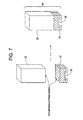
- a magnetic field generator for MRI 10 as an embodiment of this invention comprises an upper magnet unit 11 and lower magnet unit 12.
- Each of the magnet units 11 and 12 includes, but is not limited to, a yoke plate 14, a permanent magnet 16, and a pole piece 18.
- Each of the yoke plate 14 has a surface opposed to the other yoke plate, and this surface is provided with a permanent magnet 16, on which a pole piece 18 is provided.
- Each of the permanent magnets 16 includes a plurality of magnet blocks 20.
- Each of the magnet blocks 20 of the magnet unit 12 is fitted with adjacent ones, with the same magnetic pole facing upward.
- each of the magnet blocks 20 of the magnet unit 11 is fitted with adjacent ones, with the other magnetic pole facing downward.
- the permanent magnet 16 of the magnet unit 12 and the permanent magnet 16 of the magnet unit 11 are faced to each other so that different magnetic poles are opposed to each other.
- the magnet blocks 20 may be a magnet made from a ternary system compound Nd-Fe-B composed mainly of neodynium (Nd), iron (Fe) and boron (B).
- Nd neodynium
- Fe iron
- B boron
- part of Nd of the Nd-Fe- B may be replaced by dysprosium (Dy) while part of the Fe may be replaced by cobalt (Co).
- the Nd-Fe-B is known as a strong neodynium magnetic material with a maximum energy product of over 320 kJ/m 3. It should be noted here that a method for making a rare earth magnet is disclosed in detail, for example, in the United States Patent No. 4,770, 723 .
- the pair of opposed magnet units 11 and 12 are supported and magnetically connected by one or more posts 22, with a selected space in between, for example 40 cm to 60 cm.
- the magnetic field generator 10 is configured to form a uniform magnetic field in a space between the pair of pole pieces 18.
- each of the magnet blocks 20 may include a plurality (eight, for example) of magnet members.
- the magnet member is made by pressing and sintering magnetic powder into a general cube. Then the plurality of magnet members are bonded with each other to form a magnet block 20 (the magnet block 20 is affixed to a glider first, then magnetized as will be described at a later point herein.
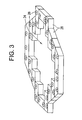
- FIGs. 2-5 depicted is an exemplary layout of a yoke plate 14 of a magnet unit 11, and 12.
- the plurality of retainers 28 is affixed to the bottom the yoke plate 14 for the upper magnet unit 11 and the top for the lower magnet unit 12.
- the plurality of retainers 28 form effectively, a perimeter substantially similar to that of the yoke plate 14 and a cavity 24, which is to be populated with the magnet blocks 20.
- a retainer 28 may include, but not be limited to, a block or clamp apparatus.
- the retainer 28 may, but need not be, constructed of a ferromagnetic material preferably, but not necessarily, the same as the yoke plate 14. Common non-magnetic materials may include but not be limited to aluminum, stainless steel, plastic G-10, and the like, as well as combinations including at least one of the foregoing.
- FIG. 3 provides a depiction of an exemplary arrangement for the plurality of retainers 28.
- a first set 30 of the plurality of retainers 28 are arranged substantially about a portion of perimeter of the yoke plate 14 of magnet unit (11 or 12) and fixed to the yoke plate 14 in a manner that facilitates assembly such as with a fastener 26, keeper, or adhesive.
- Each of the retainers 28 may be detachably affixed to the yoke plate 14 employing a fastener 26 such as screw, bolt, and the like.
- the fastener 26 may be constructed of a ferromagnetic material preferably, but not necessarily, the same as the yoke plate 14.
- the first set 30 of the plurality of retainers 28 are arranged and fixed to the yoke plate 14 in an approximately semicircular configuration about the perimeter of one side of the yoke plate 14.
- the first set 30 of the plurality of retainers 28 forming a substantially semicircular, C, U, or V-shape portion of the cavity 24, which is to be populated with the magnet blocks 20.
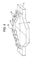
- the set of rails 40 in an exemplary embodiment comprise a series of bars exhibiting a cross section configured to facilitate magnet blocks 20 being slid along their length, yet impede motion laterally.
- the set of rails 40 are arranged and fixed to the yoke plate 14 in a manner that facilitates assembly such as with a fastener 26, keeper, or adhesive such as glue or epoxy.
- the set of rails 40 may be detachably affixed to the yoke plate 14 employing a fastener 26 such as screw, bolt, and the like.
- the set of rails 40 and fastener 26 may, but need not be, constructed of a ferromagnetic material preferably, but not necessarily, the same as the yoke plate 14.
- the set of rails 40 are depicted to be substantially bars of substantially trapezoidal cross section with, in this instance the shorter base of the trapezoidal cross section proximate to the yoke plate 14 and the larger base of the trapezoidal cross section of the set of rails 40 directed away from the yoke plate.
- the set of rails 40 are arranged in the cavity 24 formed by the retainers 28 on the yoke plate 14 extending substantially parallel to the opening of the semicircular, C, U, or V-shape portion of the cavity 24.
- the set of rails 40 are arranged substantially parallel to one another, with various lengths extending substantially side to side within the cavity 24 formed by the retainers 28. Additionally, each of the rails the set of rails 40 are spaced substantially equidistant from one another.
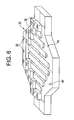
- FIG.6 depicts the yoke plate 14 with the first set of retainers 28 and rails 40 in the cavity 24 formed therefrom.
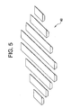
- the gliders 34 comprise a block of substantially the same footprint at the magnet blocks 20.
- the glider 34 may be constructed of a ferromagnetic material, preferably, but not necessarily, the same as the yoke plate 14.
- the glider 34 includes a slot 36 on side nearest the yoke plate 14 of matched geometry and configured to mate with the shape of the rails 40.
- the rails 40 have a substantially trapezoidal cross section and the slot 36 in the glider 34 is substantially of trapezoidal cross section.
- FIG 16 depicts a few exemplary configurations of rails 40 and gliders 34.
- the magnet blocks 20, while un-magnetized are affixed to the side opposite the slot 36 of the gliders 34.
- the magnet blocks 20 are affixed to the gliders 34 with adhesive, for example glue or epoxy.
- adhesive for example glue or epoxy.
- the magnet blocks 20 once they are affixed to the gliders 34, they may be magnetized as an assembly, thereby forming a block assembly 60 in preparation for assembly of the magnet units 11 and 12.
- Another advantage of configuring the magnet block 20 and glider 34 as described above, is that it yields a single or common block assembly 60 for all the magnet blocks 20, gliders 34, and the entirety of the magnet units 11 and 12.
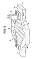
- FIG. 8 a diagram depicting the assembly of the permanent magnet 16 for each of the magnet units 11 and 12 is provided.
- a first block assembly 62 may now be slid along a first rail 42 substantially until the first block assembly encounters the retainer 28 at the distal end of the first rail 42.
- a second block assembly 64 (and subsequent block assemblies, if required) may be slid along the first rail 42 until the area provided by the first rail 42 as a first portion of the cavity 24 is filled with block assemblies 60 to completion.
- the completed first row 71 of block assemblies 60 along the length of the first rail 42.
- a retainer 28 is installed to contain and hold the first block assembly 62 and second block assembly 64 (and subsequent block assemblies if any).
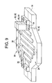
- FIG. 11 a diagram depicting the continued assembly of the permanent magnet 16 is provided.
- a third block assembly 66 may now be slid along a second rail 44 substantially until the third block assembly encounters the retainer 28 at the distal end of the second rail 44.
- a fourth block assembly 68 (and subsequent block assemblies, if required) may be slid along the second rail 44 until the area provided by the second rail 44 as a second portion of the cavity 24 is filled with block assemblies 60 to completion.
- the completed second row 72 of block assemblies 60 along the length of the second rail 44 as depicted in the figure.
- a retainer 28 is thereafter installed to contain and hold the block assemblies 60 (e.g. block assemblies 66 and subsequent block assemblies) installed on the second rail 44.
- the retainer 28 may be installed and attached with a fastener 26 such as a screw or bolt.
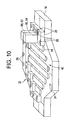
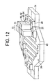
- FIG. 13 a diagram depicting the nearly completed assembly of the permanent magnet 16 is provided.
- a third and fourth row of block assemblies 74 and 76 respectively have been completed and secured with retainers 28.
- the figure depicts the assembled and secured eighth, seventh, and sixth rows, 78, 77, and 76 respectively.
- the retainers 28 may overlap more than one rail 40 and therefore more than one row e.g., 71-78 from the outermost to the innermost. Therefore, to facilitate assembly and installation, filling the rails 40 with the components is most easily accomplished by starting with the outermost rails 40 and moving toward the center. It should be appreciated that disclosed herein is just an illustrative assembly sequence. Other sequences are possible, and likely, depending upon the selected orientation for the rails 40 and retainers 28 on the yoke plate 14.
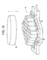
- FIG. 14 depicts a permanent magnet 16, fully populated with block assemblies 60 and secured with retainers 28.
- the top and bottom pole pieces 18 may be engaged and secured to the permanent magnet 16. It should be noted at this time, that the pole piece 18 assembly may be at a positioned as described in U.S. Patent 6,336,989 or any position during the entire magnet block assembly 60 insertion process.
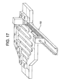
- FIG. 17 an exemplary apparatus for insertion of the block assemblies 60 is depicted.
- a magnet block pusher tool 100 configured so that it may be aligned with each of the magnet units 11 and 12 in a manner that facilitates sliding individual block assemblies 60 onto a selected rail 40.
- magnetized block assemblies 60 are placed on a magnet block pusher 100 for insertion. It will be appreciated that the block assemblies 60 may be configured to readily slid along the rail 40 as part of the assembly and yet fit tightly enough to ensure desirable tolerances for the assembled array of block assemblies of the permanent magnet 16 for each magnet unit 11, 12. The assembly process is therefore relatively easy and conventional.
- the magnet blocks 20/block assemblies 60, rails 40, and retainers 28, and other components may be located as accurately as needed with the block assemblies constrained by the rails 40, gliders 34, and retainers 28, to maintain the desired assembly tolerances for the magnet units 11 and 12. It will be appreciated further that while the layout of the rails in cooperation with the gliders is in illustration a function of a selected footprint for a magnet block 20, other configurations are readily apparent. The layout could employ a variety of configurations to satisfy the considerations necessary to construct the permanent magnet 16.
- each of the block assemblies 60 is secured by its physical constraints and the rails 40, gliders 34, and retainers 28 in the assembly process, no adhesives or bonding is required between the individual block assemblies.
- This advantage significantly enhances the assembly process as well as facilitates modification, disassembly, system upgrade, rework, or recycle of the magnet members in the future.
- Other embodiments may be employed perhaps utilizing larger tolerances in the assembly.
- This feature of the invention eliminating the need for adhesives provides significant advantages in that it facilitates rework of the magnet assembly should it be necessitated.
- the above disclosed assembly process may be substantially reversed to facilitate the disassembly process since there are no bonding agents or adhesives employed among the magnet members.
- the assembly process may be essentially reversed.
- the damaged magnet block 20/block assembly 60 may readily be removed, and replaced with a new one (e.g., raise the pole piece 18, remove a retainer 28, remove magnet blocks 60, and so forth).
Landscapes
- Physics & Mathematics (AREA)
- Health & Medical Sciences (AREA)
- Life Sciences & Earth Sciences (AREA)
- Condensed Matter Physics & Semiconductors (AREA)
- General Physics & Mathematics (AREA)
- Nuclear Medicine, Radiotherapy & Molecular Imaging (AREA)
- Engineering & Computer Science (AREA)
- Medical Informatics (AREA)
- Biophysics (AREA)
- Pathology (AREA)
- High Energy & Nuclear Physics (AREA)
- Biomedical Technology (AREA)
- Heart & Thoracic Surgery (AREA)
- Radiology & Medical Imaging (AREA)
- Molecular Biology (AREA)
- Surgery (AREA)
- Animal Behavior & Ethology (AREA)
- General Health & Medical Sciences (AREA)
- Public Health (AREA)
- Veterinary Medicine (AREA)
- Magnetic Resonance Imaging Apparatus (AREA)
Applications Claiming Priority (2)
| Application Number | Priority Date | Filing Date | Title |
|---|---|---|---|
| US64565 | 1993-05-19 | ||
| US10/064,565 US6664878B1 (en) | 2002-07-26 | 2002-07-26 | Method for assembling magnetic members for magnetic resonance imaging magnetic field generator |
Publications (2)
| Publication Number | Publication Date |
|---|---|
| EP1385017A1 EP1385017A1 (en) | 2004-01-28 |
| EP1385017B1 true EP1385017B1 (en) | 2008-09-17 |
Family
ID=29709246
Family Applications (1)
| Application Number | Title | Priority Date | Filing Date |
|---|---|---|---|
| EP03254498A Expired - Lifetime EP1385017B1 (en) | 2002-07-26 | 2003-07-18 | Method for assembling magnetic members for magnetic resonance imaging magnetic field generator |
Country Status (6)
| Country | Link |
|---|---|
| US (1) | US6664878B1 (enExample) |
| EP (1) | EP1385017B1 (enExample) |
| JP (1) | JP4344882B2 (enExample) |
| KR (1) | KR20040010393A (enExample) |
| CN (1) | CN100337585C (enExample) |
| DE (1) | DE60323573D1 (enExample) |
Families Citing this family (14)
| Publication number | Priority date | Publication date | Assignee | Title |
|---|---|---|---|---|
| US6859123B2 (en) * | 2003-04-03 | 2005-02-22 | Ge Medical Systems Global Technology Company, Llc | Methods and apparatus for positioning permanent magnetic blocks |
| US7373716B2 (en) * | 2003-10-22 | 2008-05-20 | Dexter Magnetic Technologies, Inc. | Method for constructing permanent magnet assemblies |
| JP4965426B2 (ja) * | 2004-03-03 | 2012-07-04 | コーニンクレッカ フィリップス エレクトロニクス エヌ ヴィ | 磁気共鳴イメージングシステムのための非対称の非常に短い勾配コイル |
| US7631411B2 (en) * | 2004-06-28 | 2009-12-15 | General Electric Company | Method of manufacturing support structure for open MRI |
| US6958672B1 (en) | 2004-06-30 | 2005-10-25 | General Electric Company | System and method for magnetizing blocks on a magnet assembly of an MRI device |
| EP1808126B1 (en) * | 2004-09-30 | 2012-12-26 | Hitachi Metals, Ltd. | Magnetic field generator for mri |
| US20060078844A1 (en) * | 2004-10-07 | 2006-04-13 | Goldman Paul D | Oral care systems, oral care devices and methods of use |
| GB2436365B (en) * | 2006-03-21 | 2008-04-02 | Siemens Magnet Technology Ltd | Apparatus and method for shimming the magnetic field generated by a magnet |
| GB2436364B (en) * | 2006-03-21 | 2008-07-02 | Siemens Magnet Technology Ltd | Apparatus for shimming a magnetic field |
| US8674797B2 (en) * | 2009-02-27 | 2014-03-18 | Hitachi Metals, Ltd. | Magnetic field generator |
| CN104931902A (zh) * | 2015-06-30 | 2015-09-23 | 东南大学 | 一种用于集成核磁共振磁体和探头的装置 |
| JP6407825B2 (ja) * | 2015-09-02 | 2018-10-17 | 信越化学工業株式会社 | 永久磁石磁気回路の製造方法 |
| US10847294B2 (en) | 2017-07-10 | 2020-11-24 | Aspect Imaging Ltd. | System for generating a magnetic field |
| CN109669150B (zh) * | 2018-12-29 | 2024-07-16 | 佛山瑞加图医疗科技有限公司 | 一种圆周磁体安装专用设备及安装方法 |
Family Cites Families (13)
| Publication number | Priority date | Publication date | Assignee | Title |
|---|---|---|---|---|
| CA1316375C (en) | 1982-08-21 | 1993-04-20 | Masato Sagawa | Magnetic materials and permanent magnets |
| US4931760A (en) | 1986-10-08 | 1990-06-05 | Asahi Kasei Kogyo Kabushiki Kaisha | Uniform magnetic field generator |
| GB8825529D0 (en) | 1988-11-01 | 1988-12-07 | Oxford Magnet Tech | Magnetic field generating assembly |
| GB9105286D0 (en) | 1991-03-13 | 1991-04-24 | Oxford Instr Ltd | Magnetic field generating apparatus |
| JPH0669027A (ja) | 1991-10-24 | 1994-03-11 | Hitachi Ltd | 磁場発生装置 |
| JP2699250B2 (ja) | 1993-01-22 | 1998-01-19 | 信越化学工業株式会社 | 磁場発生装置及び磁場発生装置製造方法 |
| CA2293308C (en) | 1998-04-14 | 2004-12-21 | Sumitomo Special Metals Co., Ltd. | Magnetic field generator for mri |
| JP2953659B1 (ja) | 1998-08-06 | 1999-09-27 | 住友特殊金属株式会社 | Mri用磁界発生装置およびその組立方法並びにそれに用いる磁石ユニットの組立方法 |
| JP2000139874A (ja) | 1998-09-02 | 2000-05-23 | Sumitomo Special Metals Co Ltd | Mri用磁界発生装置 |
| CN1159576C (zh) * | 1999-05-10 | 2004-07-28 | 三星电子株式会社 | 制造磁共振成像系统用的主磁体总成的方法 |
| EP1666910B1 (en) * | 1999-11-16 | 2009-03-11 | Hitachi Metals, Ltd. | Magnetic-field generator comprising a pole-piece unit |
| JP4135127B2 (ja) * | 2000-04-21 | 2008-08-20 | 信越化学工業株式会社 | 磁場発生装置の組立方法 |
| JP3788573B2 (ja) * | 2000-11-16 | 2006-06-21 | 信越化学工業株式会社 | Mri用磁気回路の組立方法 |
-
2002
- 2002-07-26 US US10/064,565 patent/US6664878B1/en not_active Expired - Lifetime
-
2003
- 2003-07-18 DE DE60323573T patent/DE60323573D1/de not_active Expired - Lifetime
- 2003-07-18 EP EP03254498A patent/EP1385017B1/en not_active Expired - Lifetime
- 2003-07-25 KR KR1020030051363A patent/KR20040010393A/ko not_active Abandoned
- 2003-07-25 JP JP2003279515A patent/JP4344882B2/ja not_active Expired - Fee Related
- 2003-07-28 CN CNB031436366A patent/CN100337585C/zh not_active Expired - Fee Related
Also Published As
| Publication number | Publication date |
|---|---|
| CN1491613A (zh) | 2004-04-28 |
| JP4344882B2 (ja) | 2009-10-14 |
| KR20040010393A (ko) | 2004-01-31 |
| US6664878B1 (en) | 2003-12-16 |
| EP1385017A1 (en) | 2004-01-28 |
| DE60323573D1 (de) | 2008-10-30 |
| CN100337585C (zh) | 2007-09-19 |
| JP2004057829A (ja) | 2004-02-26 |
Similar Documents
| Publication | Publication Date | Title |
|---|---|---|
| EP1385017B1 (en) | Method for assembling magnetic members for magnetic resonance imaging magnetic field generator | |
| CN205159023U (zh) | 磁铁单元 | |
| KR100381813B1 (ko) | Mri용 자계 발생 장치와 조립 방법 및, 자계 발생 장치용 자석 유닛의 조립 방법 | |
| EP1666910B1 (en) | Magnetic-field generator comprising a pole-piece unit | |
| CN1604240B (zh) | 具有用于主磁场调整的可动永久磁体的永久磁体装置 | |
| EP0905869A3 (en) | Linear motor mechanism for exposure apparatus, and device manufacturing method using the same | |
| CN101086524A (zh) | 拆分磁场发生器的方法 | |
| CN105280324A (zh) | 磁铁单元和磁铁单元的制造方法 | |
| JP2003527744A (ja) | 単磁石部品の製造及びマガジン化方法並びに小型化した磁石系の製造のためのその組み立て及びその磁石系 | |
| KR101069962B1 (ko) | 자기 공명 영상 장치용 자계 발생기 및 그 조립 방법 | |
| JP2004057829A5 (enExample) | ||
| EP1207400B1 (en) | Method of assembling magnetic circuitry for use in MRI system | |
| JPH08275420A (ja) | 磁気回路およびその磁極磁石の組立方法 | |
| EP1464978B1 (en) | Apparatus for assembling permanent magnets | |
| CN210575343U (zh) | 一种辅助瓦形产品定向充磁的装置 | |
| CN116721829A (zh) | 一种海尔贝克阵列磁体及其制备方法 | |
| JPH0262010A (ja) | 磁気回路の製造方法及びそれに用いる治具 |
Legal Events
| Date | Code | Title | Description |
|---|---|---|---|
| PUAI | Public reference made under article 153(3) epc to a published international application that has entered the european phase |
Free format text: ORIGINAL CODE: 0009012 |
|
| AK | Designated contracting states |
Kind code of ref document: A1 Designated state(s): AT BE BG CH CY CZ DE DK EE ES FI FR GB GR HU IE IT LI LU MC NL PT RO SE SI SK TR |
|
| AX | Request for extension of the european patent |
Extension state: AL LT LV MK |
|
| 17P | Request for examination filed |
Effective date: 20040728 |
|
| AKX | Designation fees paid |
Designated state(s): DE GB NL |
|
| 17Q | First examination report despatched |
Effective date: 20070423 |
|
| GRAP | Despatch of communication of intention to grant a patent |
Free format text: ORIGINAL CODE: EPIDOSNIGR1 |
|
| GRAS | Grant fee paid |
Free format text: ORIGINAL CODE: EPIDOSNIGR3 |
|
| GRAA | (expected) grant |
Free format text: ORIGINAL CODE: 0009210 |
|
| AK | Designated contracting states |
Kind code of ref document: B1 Designated state(s): DE GB NL |
|
| REG | Reference to a national code |
Ref country code: GB Ref legal event code: FG4D |
|
| REF | Corresponds to: |
Ref document number: 60323573 Country of ref document: DE Date of ref document: 20081030 Kind code of ref document: P |
|
| NLV1 | Nl: lapsed or annulled due to failure to fulfill the requirements of art. 29p and 29m of the patents act | ||
| PG25 | Lapsed in a contracting state [announced via postgrant information from national office to epo] |
Ref country code: NL Free format text: LAPSE BECAUSE OF FAILURE TO SUBMIT A TRANSLATION OF THE DESCRIPTION OR TO PAY THE FEE WITHIN THE PRESCRIBED TIME-LIMIT Effective date: 20080917 |
|
| PLBE | No opposition filed within time limit |
Free format text: ORIGINAL CODE: 0009261 |
|
| STAA | Information on the status of an ep patent application or granted ep patent |
Free format text: STATUS: NO OPPOSITION FILED WITHIN TIME LIMIT |
|
| 26N | No opposition filed |
Effective date: 20090618 |
|
| PGFP | Annual fee paid to national office [announced via postgrant information from national office to epo] |
Ref country code: DE Payment date: 20100728 Year of fee payment: 8 |
|
| PGFP | Annual fee paid to national office [announced via postgrant information from national office to epo] |
Ref country code: GB Payment date: 20100726 Year of fee payment: 8 |
|
| GBPC | Gb: european patent ceased through non-payment of renewal fee |
Effective date: 20110718 |
|
| PG25 | Lapsed in a contracting state [announced via postgrant information from national office to epo] |
Ref country code: DE Free format text: LAPSE BECAUSE OF NON-PAYMENT OF DUE FEES Effective date: 20120201 |
|
| REG | Reference to a national code |
Ref country code: DE Ref legal event code: R119 Ref document number: 60323573 Country of ref document: DE Effective date: 20120201 |
|
| PG25 | Lapsed in a contracting state [announced via postgrant information from national office to epo] |
Ref country code: GB Free format text: LAPSE BECAUSE OF NON-PAYMENT OF DUE FEES Effective date: 20110718 |