EP1384982B1 - System und Verfahren zum Generieren eines Fensters zur Klopferkennung in einem Gerät zum Erfassen eines Ionenstroms - Google Patents
System und Verfahren zum Generieren eines Fensters zur Klopferkennung in einem Gerät zum Erfassen eines Ionenstroms Download PDFInfo
- Publication number
- EP1384982B1 EP1384982B1 EP03077070A EP03077070A EP1384982B1 EP 1384982 B1 EP1384982 B1 EP 1384982B1 EP 03077070 A EP03077070 A EP 03077070A EP 03077070 A EP03077070 A EP 03077070A EP 1384982 B1 EP1384982 B1 EP 1384982B1
- Authority
- EP
- European Patent Office
- Prior art keywords
- knock
- signal
- ion current
- slope
- current signal
- Prior art date
- Legal status (The legal status is an assumption and is not a legal conclusion. Google has not performed a legal analysis and makes no representation as to the accuracy of the status listed.)
- Expired - Lifetime
Links
Images

Classifications
-
- G—PHYSICS
- G01—MEASURING; TESTING
- G01L—MEASURING FORCE, STRESS, TORQUE, WORK, MECHANICAL POWER, MECHANICAL EFFICIENCY, OR FLUID PRESSURE
- G01L23/00—Devices or apparatus for measuring or indicating or recording rapid changes, such as oscillations, in the pressure of steam, gas, or liquid; Indicators for determining work or energy of steam, internal-combustion, or other fluid-pressure engines from the condition of the working fluid
- G01L23/22—Devices or apparatus for measuring or indicating or recording rapid changes, such as oscillations, in the pressure of steam, gas, or liquid; Indicators for determining work or energy of steam, internal-combustion, or other fluid-pressure engines from the condition of the working fluid for detecting or indicating knocks in internal-combustion engines; Units comprising pressure-sensitive members combined with ignitors for firing internal-combustion engines
- G01L23/221—Devices or apparatus for measuring or indicating or recording rapid changes, such as oscillations, in the pressure of steam, gas, or liquid; Indicators for determining work or energy of steam, internal-combustion, or other fluid-pressure engines from the condition of the working fluid for detecting or indicating knocks in internal-combustion engines; Units comprising pressure-sensitive members combined with ignitors for firing internal-combustion engines for detecting or indicating knocks in internal combustion engines
- G01L23/225—Devices or apparatus for measuring or indicating or recording rapid changes, such as oscillations, in the pressure of steam, gas, or liquid; Indicators for determining work or energy of steam, internal-combustion, or other fluid-pressure engines from the condition of the working fluid for detecting or indicating knocks in internal-combustion engines; Units comprising pressure-sensitive members combined with ignitors for firing internal-combustion engines for detecting or indicating knocks in internal combustion engines circuit arrangements therefor
-
- F—MECHANICAL ENGINEERING; LIGHTING; HEATING; WEAPONS; BLASTING
- F02—COMBUSTION ENGINES; HOT-GAS OR COMBUSTION-PRODUCT ENGINE PLANTS
- F02D—CONTROLLING COMBUSTION ENGINES
- F02D35/00—Controlling engines, dependent on conditions exterior or interior to engines, not otherwise provided for
- F02D35/02—Controlling engines, dependent on conditions exterior or interior to engines, not otherwise provided for on interior conditions
- F02D35/021—Controlling engines, dependent on conditions exterior or interior to engines, not otherwise provided for on interior conditions using an ionic current sensor
-
- F—MECHANICAL ENGINEERING; LIGHTING; HEATING; WEAPONS; BLASTING
- F02—COMBUSTION ENGINES; HOT-GAS OR COMBUSTION-PRODUCT ENGINE PLANTS
- F02D—CONTROLLING COMBUSTION ENGINES
- F02D41/00—Electrical control of supply of combustible mixture or its constituents
- F02D41/22—Safety or indicating devices for abnormal conditions
-
- F—MECHANICAL ENGINEERING; LIGHTING; HEATING; WEAPONS; BLASTING
- F02—COMBUSTION ENGINES; HOT-GAS OR COMBUSTION-PRODUCT ENGINE PLANTS
- F02D—CONTROLLING COMBUSTION ENGINES
- F02D41/00—Electrical control of supply of combustible mixture or its constituents
- F02D41/24—Electrical control of supply of combustible mixture or its constituents characterised by the use of digital means
- F02D41/26—Electrical control of supply of combustible mixture or its constituents characterised by the use of digital means using computer, e.g. microprocessor
- F02D41/28—Interface circuits
-
- F—MECHANICAL ENGINEERING; LIGHTING; HEATING; WEAPONS; BLASTING
- F02—COMBUSTION ENGINES; HOT-GAS OR COMBUSTION-PRODUCT ENGINE PLANTS
- F02P—IGNITION, OTHER THAN COMPRESSION IGNITION, FOR INTERNAL-COMBUSTION ENGINES; TESTING OF IGNITION TIMING IN COMPRESSION-IGNITION ENGINES
- F02P17/00—Testing of ignition installations, e.g. in combination with adjusting; Testing of ignition timing in compression-ignition engines
- F02P17/12—Testing characteristics of the spark, ignition voltage or current
-
- F—MECHANICAL ENGINEERING; LIGHTING; HEATING; WEAPONS; BLASTING
- F02—COMBUSTION ENGINES; HOT-GAS OR COMBUSTION-PRODUCT ENGINE PLANTS
- F02D—CONTROLLING COMBUSTION ENGINES
- F02D41/00—Electrical control of supply of combustible mixture or its constituents
- F02D41/24—Electrical control of supply of combustible mixture or its constituents characterised by the use of digital means
- F02D41/26—Electrical control of supply of combustible mixture or its constituents characterised by the use of digital means using computer, e.g. microprocessor
- F02D41/28—Interface circuits
- F02D2041/286—Interface circuits comprising means for signal processing
-
- F—MECHANICAL ENGINEERING; LIGHTING; HEATING; WEAPONS; BLASTING
- F02—COMBUSTION ENGINES; HOT-GAS OR COMBUSTION-PRODUCT ENGINE PLANTS
- F02D—CONTROLLING COMBUSTION ENGINES
- F02D35/00—Controlling engines, dependent on conditions exterior or interior to engines, not otherwise provided for
- F02D35/02—Controlling engines, dependent on conditions exterior or interior to engines, not otherwise provided for on interior conditions
- F02D35/027—Controlling engines, dependent on conditions exterior or interior to engines, not otherwise provided for on interior conditions using knock sensors
-
- F—MECHANICAL ENGINEERING; LIGHTING; HEATING; WEAPONS; BLASTING
- F02—COMBUSTION ENGINES; HOT-GAS OR COMBUSTION-PRODUCT ENGINE PLANTS
- F02P—IGNITION, OTHER THAN COMPRESSION IGNITION, FOR INTERNAL-COMBUSTION ENGINES; TESTING OF IGNITION TIMING IN COMPRESSION-IGNITION ENGINES
- F02P17/00—Testing of ignition installations, e.g. in combination with adjusting; Testing of ignition timing in compression-ignition engines
- F02P17/12—Testing characteristics of the spark, ignition voltage or current
- F02P2017/125—Measuring ionisation of combustion gas, e.g. by using ignition circuits
- F02P2017/128—Measuring ionisation of combustion gas, e.g. by using ignition circuits for knock detection
-
- Y—GENERAL TAGGING OF NEW TECHNOLOGICAL DEVELOPMENTS; GENERAL TAGGING OF CROSS-SECTIONAL TECHNOLOGIES SPANNING OVER SEVERAL SECTIONS OF THE IPC; TECHNICAL SUBJECTS COVERED BY FORMER USPC CROSS-REFERENCE ART COLLECTIONS [XRACs] AND DIGESTS
- Y02—TECHNOLOGIES OR APPLICATIONS FOR MITIGATION OR ADAPTATION AGAINST CLIMATE CHANGE
- Y02T—CLIMATE CHANGE MITIGATION TECHNOLOGIES RELATED TO TRANSPORTATION
- Y02T10/00—Road transport of goods or passengers
- Y02T10/10—Internal combustion engine [ICE] based vehicles
- Y02T10/40—Engine management systems
Definitions
- This invention relates generally to a system and method for determining knock in an ion current sensing system of the type useful in connection with controlling ignition in an internal combustion engine.
- One approach for detecting a combustion condition involves the use of a so-called ion sense system. It is known that the combustion of an air/fuel mixture in an engine results in molecules in the cylinder being ionized. It is further known to apply a relatively high voltage across, for example, the electrodes of a spark plug just after ignition in order to produce a current between the electrodes. Such current is known as an ion current.
- the ion current that flows is, generally speaking, proportional to the number of combustion ions present in the area of, for example, the spark plug gap referred to above. Additionally, the level of such ion current may provide some measure of the level of ionization throughout the entire cylinder as combustion occurs.
- the DC level or amount of ion current is indicative of the quality of the combustion event, or whether in fact combustion has occurred at all (e.g., a misfire condition).
- An AC component of the ion current may be processed to determine the presence of knock.
- Hunninghaus et al. discloses a knock sensor having an output that is processed during dual knock windows.
- the knock signal from the sensor is processed during one angular window or period (i.e., produced by a controller based on a crank position sensor) at a point in an engine combustion cycle where a knock event is expected to occur.
- U.S. Patent No. 6,089,077 issued to Daniels entitled "MASS FRACTION BURNED AND PRESSURE ESTIMATION THROUGH SPARK PLUG ION SENSING" discloses an ion sensing system. The system of Daniels further discloses determining an inflection point in the ion signal and calculating a mass fraction on that basis.
- US-A-6 230 546 discloses a method in accordance with the preamble of claim 1.
- One object of the present invention is to provide a solution to one or more of the above-identified problems.
- One advantage of the present invention is that it permits internal generation of a knock window (i.e., internal to an ignition coil configured with the invention), thereby eliminating the need for an engine controller or the like to generate a knock window, with all its disadvantages as described in the Background.
- Another advantage is that the internally generated knock window is superior to a controller-generated knock window inasmuch as it is generated based on real data, not a guess based on crank angular position. This improvement yields a more accurate knock intensity signal.
- the knock signal (e.g., indicative of knock intensity) is sent to the engine controller over an ignition control signal line (i.e., the same line that carries the signal for controlling dwell and spark timing to the ignition coil).
- an ignition control signal line i.e., the same line that carries the signal for controlling dwell and spark timing to the ignition coil.
- the knock signal occurs on the last decreasing voltage portion of the ion current signal waveform for each ignition event. Processing the ion current signal for knock only during this time (i.e., the defined knock window) will reduce much of the noise that may be mistaken for knock in prior, conventional systems.
- An apparatus includes an ion current detection circuit, a knock detector, and a slope detector.
- the ion current detection circuit is configured to bias a spark plug in an engine cylinder for producing an ion current signal indicative of a level of combustion in the cylinder.
- the ion current signal includes knock components when knock is present in the cylinder.
- the knock detector is enabled during a knock window for generating a knock signal that is indicative of knock in the cylinder, based on the ion current signal.
- the slope detector is configured to enable the knock detector when the ion current signal exhibits a predetermined slope indicative of a time interval over which knock is to occur.
- a method of detecting knock is also presented.
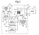
- FIG. 1 is a simplified schematic and block diagram view of an ignition apparatus 10 having an improved knock window for an ion sense system according to the invention.
- Ignition apparatus 10 includes an ion current sensing capability and is adapted for installation to a conventional spark plug 12 having spaced electrodes 14 and 16 received in a spark plug opening of an internal combustion engine 18. As known, the electrodes of spark plug 12 are proximate a combustion cylinder of engine 18.
- Figure 1 also shows an engine control unit (ECU) 20.
- ECU engine control unit
- Apparatus 10 further includes a primary winding 22, a secondary winding 24, a core 26, ignition circuitry 28, a primary switch 30, an ion current detection circuit 32 generating an ion current signal 33, a knock detector 34, and an ion current signal slope detector 36.
- the knock detector 34 generates a knock signal, which may be a knock intensity (KI) signal 38.
- ECU 20 engine control unit 20 through generation of an ignition control signal, shown as an electronic spark timing (EST) signal.
- ECU 20 in addition to spark control, may also control fuel delivery, air control and the like. In a global sense, control unit 20 is configured to control overall combustion in engine 18.
- Control unit 20 may include, for example, a central processing unit (CPU), memory, and input/output, all operating according to preprogrammed strategies.
- ECU 20 may adjust the fuel/air mixture and/or spark timing (e.g., retard spark) in response to knock intensity signal 38. Techniques for responding to knock are well known in the art.
- engine control unit 20 may be configured to provide a calculated knock window signal, designated KWI (i.e., start, end, and duration), which endures for the time period in which ECU 20 expects knock to occur.
- KWI i.e., start, end, and duration
- the knock window is defined so as to facilitate knock detection. Approaches for the generation of the knock window are known in the art (e.g ., determined generally based on the engine position or range of positions in which knock is most likely to occur, for example, 10-15 engine degrees after top dead center (TDC)).
- ignition circuitry 28 may be configured to generate a knock window on its own for use by knock detector 34, for example, as described in copending application entitled “IGNITION COIL INTEGRATED ION SENSE WITH COMBUSTION AND KNOCK OUTPUTS," U.S. application Serial No. 10/091,247 , filed on March 4, 2002, attorney Docket No. DP-304,842, assigned to the common assignee of the present invention.
- Figure 1 also shows that, in a preferred embodiment, the EST signal and KI signal 38 are multiplexed on the same physical connection between ECU 20 and ignition apparatus 10. As will be described in greater detail below, this sharing is done in a time division multiplexed manner (i.e., the same line is bi-directional).
- This multiplexing may be implemented by including tristate circuitry in ignition circuitry 28, so as to allow input of the EST signal during a first phase, while allowing generation of the KI signal 38 during a second phase distinct from the first phase.
- This feature allows elimination of a physical wire or connection between the ECU 20 and the ignition apparatus 10, thereby reducing cost and improving reliability.
- the knock intensity KI signal 38 may be provided to the ECU 20 via a separate line, as shown in phantom-line format in Figure 1 .
- a high side end of primary winding 22 may be connected to a supply voltage provided by a power supply, such as a vehicle battery (not shown) hereinafter designated "B+" in the drawings.
- Supply voltage B+ may nominally be approximately 12 volts.
- a second end of the primary winding opposite the high side end is connected to switch 30.
- the high voltage end of secondary winding 24 is coupled to spark plug 12.
- the opposite end of secondary winding 24 is connected to ion current detection circuit 32.
- Ignition circuitry 28 is configured to selectively connect, by way of switch 30, primary winding 22 to ground based on the electronic spark timing (EST) signal, for example, provided by engine control unit 20. Such connection, as is generally known in the art, will cause a primary current Ip to flow through the primary winding 22.
- Switch 30 may comprise conventional components, for example, a bipolar transistor, a MOSFET transistor, or an insulated gate bipolar transistor.
- Ignition circuitry 28 may be configured to provide additional functions, for example, applying repetitive sparks to the combustion chamber during a single combustion event. During the spark event, a spark current, designated I SPARK , flows across spaced electrodes 16, 14.
- spark plug 12 is configured so that when biased by a relatively high voltage produced by ion current detection circuit 32, an ion current may be carried across electrodes 14, 16.
- the ion current is designated I ION .
- the magnitude of a DC component of the ion current is indicative of a combustion condition, such as combustion, and/or misfire.
- a combustion condition such as combustion, and/or misfire.
- the greater the ion current i.e., due to more ionized molecules present in the cylinder
- the presence of an AC component of the ion current is indicative of a knock condition.
- a first knock mode may be defined based on the magnitude of the AC component of the ion current in a range between approximately 5-6 kHz.
- a second knock mode may be defined based on a magnitude of the AC component of the ion current in a range between approximately 10-12 kHz. It has been observed that knock will most likely start at the peak of the ion current, which may be from about 10-15 engine degrees, more preferably about 14-15 engine degrees after TDC.
- Ion current detection circuit 32 is configured to perform multiple functions. First, circuit 32 is configured to establish a bias voltage across electrodes 14, 16 for causing an ion current to flow.
- the structure for performing this function may include any one of a plurality of approaches known in the art. In one embodiment, a zener diode is employed in parallel with the storage capacitor; however, this is exemplary only and not limiting in nature.
- Circuit 32 is further configured to provide the means for sensing the ion current and for generating in response thereto an ion current signal 33.
- Knock detector 34 is configured generally, when enabled during a knock window KWI, to generate a knock signal 38 indicative of knock in the cylinder associated with the ion current being sensed.
- knock detector 34 has a knock reset signal 64 applied to an enable input.
- the knock reset signal When the knock reset signal is asserted (e.g., a logic high in one embodiment), the knock detector 34 is held in reset and no processing is allowed to occur. However, when the knock reset signal is de-asserted (e.g., a logic low), knock detector 34 is enabled to determine knock.
- the knock signal 38 may be a knock intensity signal indicative of the intensity of knock (as detected).
- Knock detector 34 may comprise various structures and functions for detecting knock known in the art.
- knock detector 34 is configured to include a filter to extract knock components from the ion current signal, a rectifier circuit to rectify the knock components and an integrator (i.e., either analog or digital) for integrating the rectified knock components contained in the ion current signal.
- the integrator is held in reset while the knock reset signal is asserted, and is thereafter allowed to perform its integration function when the knock reset signal is deasserted.
- Slope detector 36 is configured to detect when the ion current signal 33 exhibits a predetermined slope indicative of a time period during which knock is expected to occur, and enable knock detector 34 to generate the knock intensity KI signal 38.
- slope detector 36 is configured to generate a knock reset signal and provide it to knock detector 34.
- slope detector 36 asserts the knock reset signal in order to hold the knock detector 34 in reset (i.e., unable to detect noise and the like that may be mistaken for knock).
- the slope detector 36 de-asserts the knock reset signal.
- the ion current is flowing from ground up through ion current detection circuit 32, and it therefore has a negative voltage polarity in its native state.
- the last decreasing-slope voltage portion represents the interval where slope is likely to occur. Knock is unlikely to occur in the immediately preceding positive slope portion of the inverted ion current signal.
- This lifting of the knock reset signal allows the knock detector 34 to operate for detecting knock components (if present) and generating the knock intensity signal 38. It should also be appreciated that since the knock detector 34 is held in reset when knock is not likely to occur, noise or the like masquerading as knock components and occurring temporally outside the desired knock interval, will be rejected. For integration-based knock detectors, such components will not be accumulated. This rejection will minimize or eliminate false indications of knock.
- slope detector 36 may be configured to assert an enable (rather than a reset) signal when the slope indicates that knock is likely, and use this enable signal to directly enable the slope detector to operate.
- FIG. 1 shows slope detector 36 in greater detail.
- Slope detector 36 includes an amplifier 40, resistor 42, a capacitor 44, a sample and hold circuit 46, an output logic circuit 48 and a clock input 50.
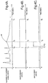
- Amplifier 40 includes an inverting input terminal configured to receive a buffered and inverted version of the ion current signal 33, designated 33' in Figure 2 (and is best shown in Figure 4A ). Amplifier 40 further includes an output terminal that is fed back to a non-inverting input terminal of amplifier 40.
- Sample and hold circuit 46 is responsive to a clock signal on input 50 for capturing and holding the prevailing level of the ion current signal at each cycle of the clock signal.
- Circuit 46 includes a sample capacitor 52, an analog switch 54, a comparator 56 and a pullup resistor 58.
- Switch 54 is configured to open and close with each cycle of the clock signal on clock input 50. When switch 54 is closed, it passes the signal on node 43, which is then applied to capacitor 52. Capacitor 52 is charged to that voltage level of node 43 (V 43 ). When the clock signal changes state, switch 54 opens, thereby leaving the applied voltage level (V 43 ) on capacitor 52. This level is then held, at least until the next clock cycle.
- Comparator 56 is configured to produce a slope indicative signal on an output node 57.
- the sampled voltage level (V 43 ) being held on capacitor 52 is provided to the inverting input terminal of comparator 56.
- the non-inverting input terminal of comparator 56 tracks (in substantial real-time) the voltage level on node 43. Depending on whether the real-time signal is higher or lower than the sampled voltage will determine whether the slope is positive or negative.
- the comparator 56 produces a logic high output (i.e., its output is allowed to be pulled high via pullup resistor 58).
- the comparator 56 when the real-time signal is lower than the sampled signal (i.e., indicative of negative slope), then the comparator 56 produces a logic low output.
- the slope indicative signal on node 57 i.e., either "0" or "1" is then provided to logic circuit 48.
- Logic circuit 48 is responsive to the clock signal and the slope indicative signal and is configured to produce the knock reset signal 64.
- Logic circuit 48 includes a shift register 60 and an AND logic gate 62.
- Shift register 60 is configured to have a predetermined number of outputs corresponding to the number of stages included in shift register 60. Shift register 60 is responsive to the clock signal to "clock in” the slope indicative signal provided to its data (“D") input terminal (i.e., clock in either a logic “0” or a logic “1"), which is then output at output Q0.
- D data
- Q0 data
- Q1 data
- Q2 data
- Q3 is discarded in the illustrated embodiment.
- the shift register 60 starts with all its ouputs Q0, Q1, Q2, Q3 equal to zero.
- AND gate 62 initially produces a logic low (zero).
- the shift register 60 will have all its stages filled with logic "1"s, wherein all its outputs Q0, Q1, Q2, Q3 will produce a logic high.
- AND gate 62 will output a logic high signal. That is, the knock reset signal will be asserted (i.e., become a logic high).
- the EST signal is generated, for example, by control unit 20 in accordance with known strategies based on a plurality of engine operating parameters as well as other inputs.
- Dwell control generally involves the control of the timing of the initiation of the spark event (i.e., at a crankshaft position and degrees relative to a top dead center position of a piston in the cylinder) as well as a duration of the charging period.
- the asserted ignition control signal EST is the command to commence charging of the ignition coil for a spark event. De-asserting the EST signal is the command to initiate spark.
- a current flag signal may be produced (a pulse) indicating that a predetermined level of primary current has been reached during a charging interval.
- the present invention may be used in a configuration where repetitive spark is applied for a single ignition event (so-called "multicharge" arrangements). Multicharging may continue (i.e., the multicharge window may remain open) until a predetermined level of combustion is obtained.
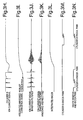
- ion current detection circuit 32 biases spark plug 12 to thereby produce an ion current I ION to the extent combustion has begun, which results in generation of an ion current signal 33, which is best shown in Figure 3H .
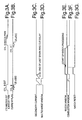
- the ion current signal may be processed ( e.g ., integrated, as known) by a combustion monitor (not shown) or similar circuit during a combustion window, which is shown in Figure 3F .
- the combustion window may "open” after a ring out delay following a spark and the dissipation of the secondary current, and "close” when the time for the next spark occurs (in the repetitive spark example).
- the resulting integrated ion current signal is shown in Figure 3I .
- multicharge operation may be discontinued, which is shown in Figure 3D as with multicharge window closing, which disables circuitry in ignition circuitry 28 from producing any additional sparks beyond the last spark that will occur from the discharge of coil 10.
- knock window signal KWI which may be based only on the angular position of the crankshaft.
- Slope detector 36 recognizes the positive slope (after a time ), which is exaggerated in the Figure 4C ) of the inverted ion current signal in Figure 4A over the interval t1 to t2, and thus asserts the knock reset signal over the interval t1 to t2.
- the knock reset signal is shown in Figure 4C .
- the knock reset signal suppresses determination of knock by knock detector 34, the knock window KWI is effectively foreshortened.
- Slope detector 36 further recognizes when the inverted ion current signal passes the inflection point ( Figure 4A ) at time t2 and begins an extended negative slope over the interval t2 to t3.
- slope detector 36 de-asserts the knock reset signal, as shown in Figure 4C .
- the knock reset signal is operative to tailor the knock window, which is generated based on angular information, to a more accurate knock window based on the actual progression of the combustion in the cylinder, as shown by the ion current. This eliminates processing during times when knock is unlikely to occur, and which may result in mistaking "noise" for knock.
- knock detector 34 in one embodiment, may be configured to process the ion current signal so that it is bandpass filtered by a bandpass filter/amplifier (not shown). The resulting signal is shown in Figure 3J .
- Knock detector 34 may then be further configured to rectify the filtered ion current signal using a rectifier (also not shown).
- Knock detector 34 according to the invention, is then configured to "window" or gate the filtered, rectified ion current signal with the knock window, as modified by the knock reset signal. As shown in Figure 3E , the start of knock processing is deferred relative to the "opening" of the knock window KWI.
- Figure 3K shows in diagrammatic fashion that portion of the filtered, rectified ion current signal (i.e., the knock components) that is permitted to contribute to the determination of knock intensity.
- Figure 3L shows one form of a knock intensity signal 38 represented as an analog, integrated signal.
- Figure 3M shows an alternate form for the knock intensity signal 38.
- Figure 3M shows the knock intensity signal 38 in the form of a pulse width modulated (PWM) signal, wherein the duration of the pulse corresponds to the intensity of the knock.
- PWM pulse width modulated
- the knock intensity PWM signal 38 has a fixed beginning time, which may be aligned with the closing of the combustion window ( Figure 3F ), and a variable ending time, as designated by the double arrow-headed line through the low-to-high transition.
- Figure 3N shows an embodiment where the knock intensity signal 38, in the form of a PWM signal 38, is time division multiplexed on the same line as the knock window signal (KWI), for the case where the ECU 20 generates the knock window signal.
- WMI knock window signal
- FIG 3A shows a further embodiment of the present invention where the knock intensity signal is time division multiplexed on the same physical line as the EST signal provided by the ECU 20, as described above.
- This arrangement is preferred where the ignition apparatus 10 itself generates the knock window signal KWI via ignition circuitry 28, eliminating the need for a KWI line from the ECU 20, as well as separate KI line. In this preferred embodiment, only one physical line is needed for the exchange of the EST and knock intensity KI signals between the ECU and the ignition apparatus 10.
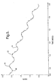
- Figure 5 shows, in greater detail, an excerpt of the negative slope portion of the inverted ion current signal.
- Another feature of the present invention is one that controls and accurately responds to transient periods of increased levels. In real world situations, while the overall voltage level is decreasing during the last portion of the inverted ion current waveform (i.e., that portion between times t2 and t3 in Figure 4A ), heavy knock could cause short times of level increases.
- Figure 5 shows points 68, 70, 72 and 74. Note that even though there is an increase between points 68 and 70, the general slope of the inverted ion current signal in Figure 5 is negative.
- a predetermined number of samples in a row would have to exhibit a positive slope (e.g., the number of stages in shift register 60) in order for the knock reset signal to be asserted by slope detector 36.
- a positive slope e.g., the number of stages in shift register 60
- both the cycle interval of the clock signal used in slope detector 36, as well as the number of stages in shift register 60 affect how brief instances of increased levels are "damped" so as to not cause the knock reset signal to be asserted. This feature enhances the robustness of the present invention when subjected to heavy knock conditions.
Landscapes
- Engineering & Computer Science (AREA)
- Chemical & Material Sciences (AREA)
- Combustion & Propulsion (AREA)
- Mechanical Engineering (AREA)
- General Engineering & Computer Science (AREA)
- Physics & Mathematics (AREA)
- General Physics & Mathematics (AREA)
- Computer Hardware Design (AREA)
- Microelectronics & Electronic Packaging (AREA)
- Combined Controls Of Internal Combustion Engines (AREA)
- Ignition Installations For Internal Combustion Engines (AREA)
Claims (6)
- Verfahren zum Erkennen von Klopfen in einem Zylinder einer Verbrennungskraftmaschine (18), umfassend den Schritt des Ermittelns von Klopfen, wenn ein Ionenstrom (IION) eine vorbestimmte Flanke aufweist, die für eine Zeitspanne (t2-t3) für das Stattfinden des Klopfens bezeichnend ist; gekennzeichnet durch die folgenden Schritte:Anlegen eines Klopfrücksetzsignals (64);Aufheben des Klopfrücksetzsignals (64), wenn das Ionenstromsignal (33) die Flanke aufweist, die für eine Zeitspanne (t2-t3) für das Stattfinden des Klopfens bezeichnend ist; undErzeugen eines Klopfsignals (KI), das für Klopfen im Zylinder bezeichnend ist, durch Verarbeiten des Ionenstromsignals (3) während eines Klopffensters (KWI), wenn das Klopfrücksetzsignal (64) aufgehoben ist.
- Verfahren nach Anspruch 1, bei dem der genannte Schritt des Erzeugens des Klopfsignals (KI) die folgenden Teilschritte aufweist:Extrahieren von Komponenten des Ionenstromsignals (33), die für Klopfen bezeichnend sind;Integrieren der extrahierten Komponenten.
- Verfahren nach Anspruch 2, bei dem der genannte Extraktionsschritt die folgenden Teilschritte aufweist:Filtern des Ionenstromsignals undGleichrichten des gefilterten Ionenstromsignals.
- Verfahren nach Anspruch 1, bei dem der genannte Schritt des Erzeugens des Klopfrücksetzsignals (64) durch die folgenden Teilschritte durchgeführt wird:Einrichten eines Taktsignals (50) mit mehreren Zyklen;Abtasten des Ionenstromsignals bei jedem Zyklus des Taktsignals undAnlegen des Klopfrücksetzsignals (64), wenn das Ionenstromsignal (33) die vorbestimmte Flanke für eine vorbestimmte Anzahl von Zyklen aufweist.
- Verfahren nach Anspruch 4, bei dem der genannte Schritt des Erzeugens des Klopfrücksetzsignals (64) durchgeführt wird, wenn die vorbestimmte Anzahl von Zyklen konsekutiv ist.
- Verfahren nach Anspruch 4, bei dem der Schritt des Anlegens des Klopfrücksetzsignals (64) die Aufgabe hat, die Verarbeitung des Ionenstromsignals zu deaktivieren.
Applications Claiming Priority (2)
| Application Number | Priority Date | Filing Date | Title |
|---|---|---|---|
| US200629 | 2002-07-22 | ||
| US10/200,629 US6615645B1 (en) | 2002-07-22 | 2002-07-22 | System and method for generating a knock determination window for an ion current sensing system |
Publications (2)
| Publication Number | Publication Date |
|---|---|
| EP1384982A1 EP1384982A1 (de) | 2004-01-28 |
| EP1384982B1 true EP1384982B1 (de) | 2008-09-24 |
Family
ID=27788725
Family Applications (1)
| Application Number | Title | Priority Date | Filing Date |
|---|---|---|---|
| EP03077070A Expired - Lifetime EP1384982B1 (de) | 2002-07-22 | 2003-07-02 | System und Verfahren zum Generieren eines Fensters zur Klopferkennung in einem Gerät zum Erfassen eines Ionenstroms |
Country Status (3)
| Country | Link |
|---|---|
| US (1) | US6615645B1 (de) |
| EP (1) | EP1384982B1 (de) |
| DE (1) | DE60323713D1 (de) |
Families Citing this family (14)
| Publication number | Priority date | Publication date | Assignee | Title |
|---|---|---|---|---|
| DE10127362C2 (de) * | 2001-06-06 | 2003-05-15 | Siemens Ag | Zündanlage für eine Brennkraftmaschine |
| JP2003161245A (ja) * | 2001-11-28 | 2003-06-06 | Denso Corp | 内燃機関の燃焼検出装置 |
| JP3614150B2 (ja) * | 2002-04-17 | 2005-01-26 | 三菱電機株式会社 | 燃焼状態検出装置 |
| JP3579404B2 (ja) * | 2002-05-27 | 2004-10-20 | 三菱電機株式会社 | 内燃機関の失火検出装置 |
| US6951201B2 (en) * | 2002-11-01 | 2005-10-04 | Visteon Global Technologies, Inc. | Method for reducing pin count of an integrated coil with driver and ionization detection circuit by multiplexing ionization and coil charge current feedback signals |
| US6776026B1 (en) | 2003-06-09 | 2004-08-17 | Delphi Technologies, Inc. | Knock sensor |
| US20050022582A1 (en) * | 2003-08-01 | 2005-02-03 | Barron Luis F. | Engine knock sensor |
| CH705544B1 (de) | 2005-05-02 | 2013-03-28 | Christoph Morach | Rohrmuffe für Kabelrohre. |
| US8132556B2 (en) * | 2008-08-29 | 2012-03-13 | Ford Global Technologies, Llc | Ignition energy management with ion current feedback to correct spark plug fouling |
| FR2939999B1 (fr) * | 2008-12-12 | 2011-02-25 | E2V Semiconductors | Capteur d'image a double transfert de charges pour grande dynamique et procede de lecture |
| JP6005928B2 (ja) * | 2011-12-01 | 2016-10-12 | ダイヤモンド電機株式会社 | 内燃機関の燃焼状態判定方法 |
| IT201700055908A1 (it) * | 2017-05-23 | 2018-11-23 | Fpt Ind Spa | Metodo e sistema di controllo di combustione in una camera di combustione di un motore a combustione interna |
| US10995726B2 (en) * | 2018-03-29 | 2021-05-04 | Woodward, Inc. | Current profile optimization |
| WO2022235872A1 (en) * | 2021-05-05 | 2022-11-10 | Cummins Inc. | Systems and methods for conducting diagnostic of ignition system |
Family Cites Families (8)
| Publication number | Priority date | Publication date | Assignee | Title |
|---|---|---|---|---|
| US5537855A (en) | 1994-06-30 | 1996-07-23 | Motorola, Inc. | Knock detection method and apparatus with dual integration windows |
| US5534781A (en) | 1994-08-15 | 1996-07-09 | Chrysler Corporation | Combustion detection via ionization current sensing for a "coil-on-plug" ignition system |
| JP3472661B2 (ja) * | 1996-03-28 | 2003-12-02 | 三菱電機株式会社 | 内燃機関用イオン電流検出装置 |
| DE69615698T2 (de) * | 1996-06-20 | 2002-04-18 | Delphi Technologies, Inc. | Methode zur zündsteuerung in verbrennungsmotoren |
| US6089077A (en) | 1997-06-26 | 2000-07-18 | Cooper Automotive Products, Inc. | Mass fraction burned and pressure estimation through spark plug ion sensing |
| DE19755257A1 (de) * | 1997-12-12 | 1999-06-24 | Daimler Chrysler Ag | Verfahren zur Erkennung von klopfender Verbrennung aus einem Ionenstromsignal bei Brennkraftmaschinen |
| GB2334549B (en) * | 1998-02-20 | 2001-11-28 | Gen Motors Corp | Arrangement and method for knock detection in combustion engines |
| US6338267B1 (en) | 2000-02-17 | 2002-01-15 | Delphi Technologies, Inc. | System for rejecting noise in ignition knock data |
-
2002
- 2002-07-22 US US10/200,629 patent/US6615645B1/en not_active Expired - Fee Related
-
2003
- 2003-07-02 EP EP03077070A patent/EP1384982B1/de not_active Expired - Lifetime
- 2003-07-02 DE DE60323713T patent/DE60323713D1/de not_active Expired - Lifetime
Also Published As
| Publication number | Publication date |
|---|---|
| EP1384982A1 (de) | 2004-01-28 |
| US6615645B1 (en) | 2003-09-09 |
| DE60323713D1 (de) | 2008-11-06 |
Similar Documents
| Publication | Publication Date | Title |
|---|---|---|
| US6615811B1 (en) | Ignition coil integrated ion sense with combustion and knock outputs | |
| US6615645B1 (en) | System and method for generating a knock determination window for an ion current sensing system | |
| US5778855A (en) | Combustion stability control for lean burn engines | |
| US5483818A (en) | Method and apparatus for detecting ionic current in the ignition system of an internal combustion engine | |
| US6752004B2 (en) | Misfire detection apparatus for internal combustion engine | |
| US4539957A (en) | Ignition timing control system for internal combustion engines | |
| JP2001073914A (ja) | 内燃機関のノック制御装置 | |
| DE69722534T2 (de) | Verfahren und Vorrichtung zur Klopferkennung für eine Brennkraftmaschine | |
| US5821754A (en) | Ignition system for an internal combustion engine | |
| US6886547B2 (en) | Ignition system with multiplexed combustion signals | |
| US6803765B2 (en) | Misfire detection system for internal combustion engines | |
| US6029631A (en) | Method of identifying the combustion chamber of a combustion engine that is in the compression stroke, and a method and device for starting a combustion engine | |
| US6367318B1 (en) | Multicharge ignition system having combustion feedback for termination | |
| JP2001082309A (ja) | 内燃機関のノック検出装置 | |
| US20020144539A1 (en) | Ignition system with ion current detecting circuit | |
| US6263727B1 (en) | Make voltage bias ion sense misfired detection system | |
| US4452206A (en) | Ignition timing control system for internal combustion engines | |
| US4512310A (en) | Ignition timing control system for internal combustion engines | |
| JP3533283B2 (ja) | 内燃機関の失火検出方法及び装置 | |
| JP4445009B2 (ja) | 内燃機関の燃焼状態検出方法及び装置 | |
| US4416235A (en) | Ignition timing control apparatus for internal combustion engine | |
| JP2006077762A (ja) | 内燃機関用イオン電流検出装置 | |
| JPH04339175A (ja) | 火花点火機関の失火検出装置 | |
| EP1092968B1 (de) | Verfahren zur Verbrennungsanalyse für einen Verbrennungsmotor | |
| US11939944B2 (en) | Electronic device to control an ignition coil of an internal combustion engine and electronic ignition system thereof for detecting a misfire in the internal combustion engine |
Legal Events
| Date | Code | Title | Description |
|---|---|---|---|
| PUAI | Public reference made under article 153(3) epc to a published international application that has entered the european phase |
Free format text: ORIGINAL CODE: 0009012 |
|
| AK | Designated contracting states |
Kind code of ref document: A1 Designated state(s): AT BE BG CH CY CZ DE DK EE ES FI FR GB GR HU IE IT LI LU MC NL PT RO SE SI SK TR |
|
| AX | Request for extension of the european patent |
Extension state: AL LT LV MK |
|
| 17P | Request for examination filed |
Effective date: 20040728 |
|
| AKX | Designation fees paid |
Designated state(s): DE FR GB |
|
| 17Q | First examination report despatched |
Effective date: 20061228 |
|
| GRAP | Despatch of communication of intention to grant a patent |
Free format text: ORIGINAL CODE: EPIDOSNIGR1 |
|
| GRAS | Grant fee paid |
Free format text: ORIGINAL CODE: EPIDOSNIGR3 |
|
| GRAA | (expected) grant |
Free format text: ORIGINAL CODE: 0009210 |
|
| AK | Designated contracting states |
Kind code of ref document: B1 Designated state(s): DE FR GB |
|
| REG | Reference to a national code |
Ref country code: GB Ref legal event code: FG4D |
|
| REF | Corresponds to: |
Ref document number: 60323713 Country of ref document: DE Date of ref document: 20081106 Kind code of ref document: P |
|
| PLBE | No opposition filed within time limit |
Free format text: ORIGINAL CODE: 0009261 |
|
| STAA | Information on the status of an ep patent application or granted ep patent |
Free format text: STATUS: NO OPPOSITION FILED WITHIN TIME LIMIT |
|
| 26N | No opposition filed |
Effective date: 20090625 |
|
| GBPC | Gb: european patent ceased through non-payment of renewal fee |
Effective date: 20090702 |
|
| REG | Reference to a national code |
Ref country code: FR Ref legal event code: ST Effective date: 20100331 |
|
| PG25 | Lapsed in a contracting state [announced via postgrant information from national office to epo] |
Ref country code: FR Free format text: LAPSE BECAUSE OF NON-PAYMENT OF DUE FEES Effective date: 20090731 |
|
| PG25 | Lapsed in a contracting state [announced via postgrant information from national office to epo] |
Ref country code: GB Free format text: LAPSE BECAUSE OF NON-PAYMENT OF DUE FEES Effective date: 20090702 |
|
| PGFP | Annual fee paid to national office [announced via postgrant information from national office to epo] |
Ref country code: DE Payment date: 20160726 Year of fee payment: 14 |
|
| REG | Reference to a national code |
Ref country code: DE Ref legal event code: R119 Ref document number: 60323713 Country of ref document: DE |
|
| PG25 | Lapsed in a contracting state [announced via postgrant information from national office to epo] |
Ref country code: DE Free format text: LAPSE BECAUSE OF NON-PAYMENT OF DUE FEES Effective date: 20180201 |