EP1384901B1 - Regelverfahren zum Druckaufbau mittels Druckübersetzern, insbesondere zum Prüfen der Druckfestigkeit von Rohren - Google Patents
Regelverfahren zum Druckaufbau mittels Druckübersetzern, insbesondere zum Prüfen der Druckfestigkeit von Rohren Download PDFInfo
- Publication number
- EP1384901B1 EP1384901B1 EP03014013.1A EP03014013A EP1384901B1 EP 1384901 B1 EP1384901 B1 EP 1384901B1 EP 03014013 A EP03014013 A EP 03014013A EP 1384901 B1 EP1384901 B1 EP 1384901B1
- Authority
- EP
- European Patent Office
- Prior art keywords
- pressure
- intensifiers
- piston
- control method
- plunger
- Prior art date
- Legal status (The legal status is an assumption and is not a legal conclusion. Google has not performed a legal analysis and makes no representation as to the accuracy of the status listed.)
- Expired - Lifetime
Links
- 238000012360 testing method Methods 0.000 title claims description 13
- 238000000034 method Methods 0.000 title claims description 6
- 230000006835 compression Effects 0.000 title description 8
- 238000007906 compression Methods 0.000 title description 8
- 239000012530 fluid Substances 0.000 claims description 7
- 230000001133 acceleration Effects 0.000 claims description 5
- 230000001419 dependent effect Effects 0.000 claims description 5
- 230000033001 locomotion Effects 0.000 claims description 4
- 239000010720 hydraulic oil Substances 0.000 claims description 2
- 238000011144 upstream manufacturing Methods 0.000 claims 2
- 238000007789 sealing Methods 0.000 claims 1
- XLYOFNOQVPJJNP-UHFFFAOYSA-N water Substances O XLYOFNOQVPJJNP-UHFFFAOYSA-N 0.000 description 6
- 239000003921 oil Substances 0.000 description 5
- 239000007788 liquid Substances 0.000 description 3
- 230000010355 oscillation Effects 0.000 description 3
- 238000010276 construction Methods 0.000 description 2
- 230000007704 transition Effects 0.000 description 2
- 230000002411 adverse Effects 0.000 description 1
- 238000010586 diagram Methods 0.000 description 1
- 239000000839 emulsion Substances 0.000 description 1
- 239000003344 environmental pollutant Substances 0.000 description 1
- 239000012073 inactive phase Substances 0.000 description 1
- 230000003993 interaction Effects 0.000 description 1
- 238000012423 maintenance Methods 0.000 description 1
- 239000012071 phase Substances 0.000 description 1
- 231100000719 pollutant Toxicity 0.000 description 1
- 230000001360 synchronised effect Effects 0.000 description 1
- 239000002569 water oil cream Substances 0.000 description 1
Images

Classifications
-
- F—MECHANICAL ENGINEERING; LIGHTING; HEATING; WEAPONS; BLASTING
- F04—POSITIVE - DISPLACEMENT MACHINES FOR LIQUIDS; PUMPS FOR LIQUIDS OR ELASTIC FLUIDS
- F04B—POSITIVE-DISPLACEMENT MACHINES FOR LIQUIDS; PUMPS
- F04B9/00—Piston machines or pumps characterised by the driving or driven means to or from their working members
- F04B9/08—Piston machines or pumps characterised by the driving or driven means to or from their working members the means being fluid
- F04B9/10—Piston machines or pumps characterised by the driving or driven means to or from their working members the means being fluid the fluid being liquid
- F04B9/109—Piston machines or pumps characterised by the driving or driven means to or from their working members the means being fluid the fluid being liquid having plural pumping chambers
- F04B9/117—Piston machines or pumps characterised by the driving or driven means to or from their working members the means being fluid the fluid being liquid having plural pumping chambers the pumping members not being mechanically connected to each other
- F04B9/1172—Piston machines or pumps characterised by the driving or driven means to or from their working members the means being fluid the fluid being liquid having plural pumping chambers the pumping members not being mechanically connected to each other the movement of each pump piston in the two directions being obtained by a double-acting piston liquid motor
-
- F—MECHANICAL ENGINEERING; LIGHTING; HEATING; WEAPONS; BLASTING
- F04—POSITIVE - DISPLACEMENT MACHINES FOR LIQUIDS; PUMPS FOR LIQUIDS OR ELASTIC FLUIDS
- F04B—POSITIVE-DISPLACEMENT MACHINES FOR LIQUIDS; PUMPS
- F04B11/00—Equalisation of pulses, e.g. by use of air vessels; Counteracting cavitation
- F04B11/005—Equalisation of pulses, e.g. by use of air vessels; Counteracting cavitation using two or more pumping pistons
-
- F—MECHANICAL ENGINEERING; LIGHTING; HEATING; WEAPONS; BLASTING
- F15—FLUID-PRESSURE ACTUATORS; HYDRAULICS OR PNEUMATICS IN GENERAL
- F15B—SYSTEMS ACTING BY MEANS OF FLUIDS IN GENERAL; FLUID-PRESSURE ACTUATORS, e.g. SERVOMOTORS; DETAILS OF FLUID-PRESSURE SYSTEMS, NOT OTHERWISE PROVIDED FOR
- F15B11/00—Servomotor systems without provision for follow-up action; Circuits therefor
- F15B11/02—Systems essentially incorporating special features for controlling the speed or actuating force of an output member
- F15B11/04—Systems essentially incorporating special features for controlling the speed or actuating force of an output member for controlling the speed
- F15B11/046—Systems essentially incorporating special features for controlling the speed or actuating force of an output member for controlling the speed depending on the position of the working member
- F15B11/048—Systems essentially incorporating special features for controlling the speed or actuating force of an output member for controlling the speed depending on the position of the working member with deceleration control
-
- F—MECHANICAL ENGINEERING; LIGHTING; HEATING; WEAPONS; BLASTING
- F15—FLUID-PRESSURE ACTUATORS; HYDRAULICS OR PNEUMATICS IN GENERAL
- F15B—SYSTEMS ACTING BY MEANS OF FLUIDS IN GENERAL; FLUID-PRESSURE ACTUATORS, e.g. SERVOMOTORS; DETAILS OF FLUID-PRESSURE SYSTEMS, NOT OTHERWISE PROVIDED FOR
- F15B19/00—Testing; Calibrating; Fault detection or monitoring; Simulation or modelling of fluid-pressure systems or apparatus not otherwise provided for
- F15B19/005—Fault detection or monitoring
-
- G—PHYSICS
- G01—MEASURING; TESTING
- G01N—INVESTIGATING OR ANALYSING MATERIALS BY DETERMINING THEIR CHEMICAL OR PHYSICAL PROPERTIES
- G01N3/00—Investigating strength properties of solid materials by application of mechanical stress
- G01N3/08—Investigating strength properties of solid materials by application of mechanical stress by applying steady tensile or compressive forces
- G01N3/10—Investigating strength properties of solid materials by application of mechanical stress by applying steady tensile or compressive forces generated by pneumatic or hydraulic pressure
- G01N3/12—Pressure testing
-
- F—MECHANICAL ENGINEERING; LIGHTING; HEATING; WEAPONS; BLASTING
- F04—POSITIVE - DISPLACEMENT MACHINES FOR LIQUIDS; PUMPS FOR LIQUIDS OR ELASTIC FLUIDS
- F04B—POSITIVE-DISPLACEMENT MACHINES FOR LIQUIDS; PUMPS
- F04B2201/00—Pump parameters
- F04B2201/02—Piston parameters
- F04B2201/0201—Position of the piston
-
- F—MECHANICAL ENGINEERING; LIGHTING; HEATING; WEAPONS; BLASTING
- F04—POSITIVE - DISPLACEMENT MACHINES FOR LIQUIDS; PUMPS FOR LIQUIDS OR ELASTIC FLUIDS
- F04B—POSITIVE-DISPLACEMENT MACHINES FOR LIQUIDS; PUMPS
- F04B2203/00—Motor parameters
- F04B2203/09—Motor parameters of linear hydraulic motors
- F04B2203/0903—Position of the driving piston
-
- F—MECHANICAL ENGINEERING; LIGHTING; HEATING; WEAPONS; BLASTING
- F15—FLUID-PRESSURE ACTUATORS; HYDRAULICS OR PNEUMATICS IN GENERAL
- F15B—SYSTEMS ACTING BY MEANS OF FLUIDS IN GENERAL; FLUID-PRESSURE ACTUATORS, e.g. SERVOMOTORS; DETAILS OF FLUID-PRESSURE SYSTEMS, NOT OTHERWISE PROVIDED FOR
- F15B2211/00—Circuits for servomotor systems
- F15B2211/20—Fluid pressure source, e.g. accumulator or variable axial piston pump
- F15B2211/21—Systems with pressure sources other than pumps, e.g. with a pyrotechnical charge
-
- F—MECHANICAL ENGINEERING; LIGHTING; HEATING; WEAPONS; BLASTING
- F15—FLUID-PRESSURE ACTUATORS; HYDRAULICS OR PNEUMATICS IN GENERAL
- F15B—SYSTEMS ACTING BY MEANS OF FLUIDS IN GENERAL; FLUID-PRESSURE ACTUATORS, e.g. SERVOMOTORS; DETAILS OF FLUID-PRESSURE SYSTEMS, NOT OTHERWISE PROVIDED FOR
- F15B2211/00—Circuits for servomotor systems
- F15B2211/20—Fluid pressure source, e.g. accumulator or variable axial piston pump
- F15B2211/25—Pressure control functions
-
- F—MECHANICAL ENGINEERING; LIGHTING; HEATING; WEAPONS; BLASTING
- F15—FLUID-PRESSURE ACTUATORS; HYDRAULICS OR PNEUMATICS IN GENERAL
- F15B—SYSTEMS ACTING BY MEANS OF FLUIDS IN GENERAL; FLUID-PRESSURE ACTUATORS, e.g. SERVOMOTORS; DETAILS OF FLUID-PRESSURE SYSTEMS, NOT OTHERWISE PROVIDED FOR
- F15B2211/00—Circuits for servomotor systems
- F15B2211/20—Fluid pressure source, e.g. accumulator or variable axial piston pump
- F15B2211/265—Control of multiple pressure sources
- F15B2211/2652—Control of multiple pressure sources without priority
-
- F—MECHANICAL ENGINEERING; LIGHTING; HEATING; WEAPONS; BLASTING
- F15—FLUID-PRESSURE ACTUATORS; HYDRAULICS OR PNEUMATICS IN GENERAL
- F15B—SYSTEMS ACTING BY MEANS OF FLUIDS IN GENERAL; FLUID-PRESSURE ACTUATORS, e.g. SERVOMOTORS; DETAILS OF FLUID-PRESSURE SYSTEMS, NOT OTHERWISE PROVIDED FOR
- F15B2211/00—Circuits for servomotor systems
- F15B2211/30—Directional control
- F15B2211/305—Directional control characterised by the type of valves
- F15B2211/30505—Non-return valves, i.e. check valves
-
- F—MECHANICAL ENGINEERING; LIGHTING; HEATING; WEAPONS; BLASTING
- F15—FLUID-PRESSURE ACTUATORS; HYDRAULICS OR PNEUMATICS IN GENERAL
- F15B—SYSTEMS ACTING BY MEANS OF FLUIDS IN GENERAL; FLUID-PRESSURE ACTUATORS, e.g. SERVOMOTORS; DETAILS OF FLUID-PRESSURE SYSTEMS, NOT OTHERWISE PROVIDED FOR
- F15B2211/00—Circuits for servomotor systems
- F15B2211/30—Directional control
- F15B2211/305—Directional control characterised by the type of valves
- F15B2211/3056—Assemblies of multiple valves
- F15B2211/30565—Assemblies of multiple valves having multiple valves for a single output member, e.g. for creating higher valve function by use of multiple valves like two 2/2-valves replacing a 5/3-valve
-
- F—MECHANICAL ENGINEERING; LIGHTING; HEATING; WEAPONS; BLASTING
- F15—FLUID-PRESSURE ACTUATORS; HYDRAULICS OR PNEUMATICS IN GENERAL
- F15B—SYSTEMS ACTING BY MEANS OF FLUIDS IN GENERAL; FLUID-PRESSURE ACTUATORS, e.g. SERVOMOTORS; DETAILS OF FLUID-PRESSURE SYSTEMS, NOT OTHERWISE PROVIDED FOR
- F15B2211/00—Circuits for servomotor systems
- F15B2211/80—Other types of control related to particular problems or conditions
- F15B2211/855—Testing of fluid pressure systems
-
- Y—GENERAL TAGGING OF NEW TECHNOLOGICAL DEVELOPMENTS; GENERAL TAGGING OF CROSS-SECTIONAL TECHNOLOGIES SPANNING OVER SEVERAL SECTIONS OF THE IPC; TECHNICAL SUBJECTS COVERED BY FORMER USPC CROSS-REFERENCE ART COLLECTIONS [XRACs] AND DIGESTS
- Y10—TECHNICAL SUBJECTS COVERED BY FORMER USPC
- Y10T—TECHNICAL SUBJECTS COVERED BY FORMER US CLASSIFICATION
- Y10T137/00—Fluid handling
- Y10T137/0318—Processes
- Y10T137/0396—Involving pressure control
Definitions
- the invention relates to a control method for pressure build-up by means of pressure booster in a press for testing the pressure resistance of pipes having the features specified in the preamble of the independent claim, as by the FR 2 689 571 A become known, in which the cylinders of the pressure booster should work at strictly the same speeds.
- a pipe tester is for example from the SU 717 595 A known.
- a complex, expensive construction also bring known, double-acting pressure booster with it, which also caused by the switching of the piston movement large pressure fluctuations in the pressure medium.
- the above applies not only to test presses, but to any other pressure build-up device in which a liquid is pressurized.
- the US 4,666,374 A provides for distributing an amount of liquid targeted to several hydraulic cylinders.
- the invention is therefore an object of the invention to provide a control method of the type mentioned, with which can avoid the disadvantages mentioned and in particular allow a simple, inexpensive construction and longer service life.
- This object is achieved in that shortly before a plunger of a piston-cylinder unit of a first pressure booster has ended its stroke and has approached its end position, reduces its speed and at the same time a plunger of a piston-cylinder unit of an operational further pressure booster in Movement is set, wherein for detecting the beginning of the deceleration or acceleration of the pressure booster Wegweginraumen determine the respective position of the plunger and enter into the control unit.
- the filling and compression volume to be introduced is subject to no limitation, since several of the simple, small pressure intensifiers alternate and if necessary re-establish, i. starting with the first pressure booster starting in the manner according to the invention can be repeatedly actuated repeatedly until the desired, large volume and the test pressure is given.
- This can advantageously be determined by the fact that a pressure sensor for receiving the pipe internal pressure is connected to the control unit. Depending on this, then also the pressure intensifier can be controlled.
- longer service life of the components, in particular the control valves are achieved because they are not arranged on the water side, but on the oil side.
- the FIG. 1 shows a tube to be tested 1, the ends of which are completed by patch caps 2 of the like.
- a media supply (pressure fluid) 3 eg a filling container, a basin or a centrifugal pump, a tank 3 ', a line 27, a valve 26 and a pressure line 8
- the tube 1 as long with a pressure medium, eg a water-oil Emulsion, are filled until all the air has escaped from the tube 1 and inside the tube of the desired test pressure prevails.
- a pressure medium eg a water-oil Emulsion
- the tube 1 can first be filled in the direct way and then the pressure build-up can be carried out.
- the pressure intensifier D1 is applied.
- the pressure medium has been promoted via the check valve 6 and the line 4 of the media supply 3.
- the check valve 6 closes while the check valve 6 '"opens, so that the pressure medium reaches the tube 1 via the pressure line 8.
- the plunger 12 becomes ready for use further pressure booster D2 set in motion, which continues in the sequence, the filling or the pressure build-up of the tube 1. This interplay can be carried out until the final compression volume is reached, with the respectively non-activated pressure booster being supplied with the pressure medium from the media supply 3 required for the subsequent stroke after the working stroke.
- the piston-cylinder units 14, 16 and 15, 17 are double-acting cylinders driven by hydraulic oil.
- the control of the piston-cylinder units via arranged on the oil side II control valves 18, 19 which are connected to a conventional oil supply.
- the control valves 18, 19 are controlled by a control unit 23, via which the two pressure booster D1, D2 are combined to form an operating system with the above-described operation of the piston or plunger 11, 12.
- a control unit 23 Wegmeß wornen W1 and W2 provided in the embodiment formed as a pinion 25, 25 ', which mesh with rack portions of the piston rods 13, 13' and so determine the respective position of the plunger 11 and 12.
- the control unit 23 can still process signals from a pressure sensor 5, which determines the pressure in the tube 1 via the pressure line 8.
- Setpoint values for the control unit 23 can be input via a connection 24.
Landscapes
- Engineering & Computer Science (AREA)
- Mechanical Engineering (AREA)
- General Engineering & Computer Science (AREA)
- Physics & Mathematics (AREA)
- Fluid Mechanics (AREA)
- Health & Medical Sciences (AREA)
- Life Sciences & Earth Sciences (AREA)
- Chemical & Material Sciences (AREA)
- Analytical Chemistry (AREA)
- Biochemistry (AREA)
- General Health & Medical Sciences (AREA)
- General Physics & Mathematics (AREA)
- Immunology (AREA)
- Pathology (AREA)
- Investigating Strength Of Materials By Application Of Mechanical Stress (AREA)
- Supply Devices, Intensifiers, Converters, And Telemotors (AREA)
Description
- Die Erfindung betrifft ein Regelverfahren zum Druckaufbau mittels Druckübersetzern bei einer Presse zum Prüfen der Druckfestigkeit von Rohren mit den im Oberbegriff des unabhängigen Anspruchs angegebenen Merkmalen, wie durch die
FR 2 689 571 A SU 717 595 A - Um eine Flüssigkeit unter Druck zu setzen, sind beispielsweise handelsübliche Hochdruckplungerpumpen bekannt, von denen bei Rohrprüfpressen mehrere zum Einsatz kommen. Hier macht sich die Oszillation aufgrund der Anzahl der vorhandenen Kolben nachteilig bemerkbar, was sich aus den Prüfprotokollen ergibt, die zu jedem geprüften Rohr erstellt werden müssen. Eine Regelung auf einen bestimmten Prüfdruck erfordert zudem ein zusätzliches Regelventil, das sich nur auf der Hochdruckseite vorsehen läßt. Da es sich bei dem Druckmedium von Prüfpressen regelmäßig um Wasser, gegebenenfalls eine Wasseremulsion handelt, in dem sich häufig aus den zu prüfenden Rohren stammende Schadstoffe wie Sinter befinden, unterliegt das Regelventil einem hohen Verschleiß.
- Im praktischen Betrieb werden daher an Prüfpressen einfache Druckübersetzer, bestehend aus in einem Zylinder angeordneten Plunger und diesen beaufschlagende Kolben-Zylinder-Einheit, eingesetzt. Als Vorteil eines solchen Druckübersetzers liegt vor, daß die Druckregelung auf der Ölseite und folglich mit geringem Verschleiß an den Regelventilen möglich ist. Außerdem entsteht keine Oszillation während des Druckaufbaus und des Druckhaltens. Als Nachteil hat sich aber herausgestellt, daß das Nutzvolumen auf der Wasserseite immer größer sein muß als das Kompressionsverhalten im Prüfling, d.h. im zu prüfenden Rohr. Wenn nun Prüflinge ein großes Kompressionsvolumen erfordern, wie im Falle von Großrohren, macht das den Einsatz von sehr großen und damit teuren Druckübersetzern notwendig. Eine aufwendige, teure Bauweise bringen auch bekannte, doppeltwirkende Druckübersetzer mit sich, bei denen außerdem durch die Umschaltung der Kolbenbewegung große Druckschwankungen im Druckmedium entstehen. Das Vorgenannte gilt nicht nur für Prüfpressen, sondern für jede andere Vorrichtung zum Druckaufbau, bei denen eine Flüssigkeit unter Druck gesetzt wird.
- Bei einem aus der
US 4.021.156 A bekannten Hochdruck-Hydrauliksystem wird davon ausgegangen, dass sich ein erster Druckübersetzer in einer aktiven Betriebsphase und ein zweiter Druckübersetzer in einer inaktiven Betriebsphase befindet. Wenn der Kolben des einen Druckübersetzers seinen Antriebshub beendet hat, wird dem Kolben des anderen Druckübersetzers eine zusätzliche Hydraulikflüssigkeitsmenge aufgeschaltet. - Das Aufschalten zusätzlicher Hydraulikflüssigkeiten, wenn der Kolben eines Druckübersetzers seine Endlage erreicht hat, auf den anderen Druckübersetzer wird weiterhin durch die
GB 2 175 352 A - Die
US 4.666.374 A sieht vor, eine Flüssigkeitsmenge gezielt auf mehrere Hydraulikzylinder zu verteilen. - Der Erfindung liegt daher die Aufgabe zugrunde, ein Regelverfahren der eingangs genannten Art zu schaffen, mit dem sich die genannten Nachteile vermeiden lassen und das insbesondere einen einfachen, kostengünstigen Aufbau und höhere Standzeiten ermöglichen.
- Diese Aufgabe wird erfindungsgemäß dadurch gelöst, dass kurz bevor ein Plunger einer Kolben-Zylinder-Einheit eines ersten Druckübersetzers seinen Arbeitshub beendet und sich seiner Endlage genähert hat, seine Geschwindigkeit reduziert und gleichzeitig damit ein Plunger einer Kolben-Zylinder-Einheit eines betriebsbereiten weiteren Druckübersetzers in Bewegung gesetzt wird, wobei zur Erfassung des Beginns des Verzögerns bzw. Beschleunigens der Druckübersetzer die Wegmesseinrichtungen die jeweilige Position der Plunger ermitteln und in die Regeleinheit eingeben.
- Das läßt sich vorteilhaft mehrfach wiederholt durchführen. Indem somit einerseits die Geschwindigkeit reduziert und davon abhängig gleichzeitig ein nachfolgend beaufschlagter Druckübersetzer beschleunigt wird, wird ein kontinuierlicher Druckaufbau ohne einen Druckeinbruch erreicht und damit ein Überschwingen beim Komprimieren verhindert. Denn das Abbremsen und Beschleunigen wird synchronisiert. Die Summe der von den beiden Druckübersetzern geförderten Druckflüssigkeit bleibt stets konstant bzw. kann einen beabsichtigten zeitlichen Verlauf einnehmen.
- Es lassen sich damit trotz der Verwendung kleiner, kostengünstiger handelsüblicher und baugleicher Druckübersetzer auch die für Rohrprüfpressen bei Großrohren benötigten erheblichen Kompressionsvolumina erreichen. Somit sind groß bauende, in Sonderanfertigung herzustellende und damit teure Einzeldruckübersetzer entbehrlich.
- Das einzubringende Füll- und Kompressionsvolumen unterliegt gleichwohl keiner Begrenzung, da mehrere der einfachen, kleinen Druckübersetzer alternierend und gegebenenfalls von neuem, d.h. jeweils mit dem ersten Druckübersetzer beginnend in der erfindungsgemäßen Weise mehrfach wiederholt betätigt werden können, bis das gewünschte, große Volumen und der Prüfdruck gegeben ist. Dies läßt sich vorteilhaft dadurch feststellen, daß an die Regeleinheit ein Drucksensor zur Aufnahme des Rohrinnendrucks angeschlossen wird. Hiervon abhängig lassen sich dann auch die Druckübersetzer ansteuern. Schließlich werden höhere Standzeiten der Komponenten, insbesondere der Regelventile erreicht, weil diese nicht auf der Wasserseite, sondern auf der Ölseite angeordnet sind. Weiterhin ist es auch möglich, zum Dekomprimieren das Rohr mittels der Druckübersetzer zu leeren, d.h. das Druckmittel raus zu fördern.
- Weitere Merkmale und Einzelheiten der Erfindung ergeben sich aus den Ansprüchen und der nachfolgenden Beschreibung anhand eines in den Zeichnungen schematisch dargestellten Ausführungsbeispiels der Erfindung. Es zeigen:
- Fig. 1
- einen Systemaufbau mit Hydraulikplan zum Druckaufbau mittels Druckübersetzern; und
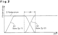
- Fig. 2
- ein Fördernstrom-/Zeit-Diagramm.
- Die
Figur 1 zeigt ein zu prüfendes Rohr 1, dessen Enden durch aufgesetzte Kappen 2 der dergleichen abgeschlossen sind. Über eine Medienversorgung (Druckflüssigkeit) 3, z.B. ein Füllbehälter, ein Becken oder eine Kreiselpumpe, einen Tank 3', eine Leitung 27, ein Ventil 26 und eine Druckleitung 8 kann das Rohr 1 so lange mit einem Druckmedium, z.B. eine Wasser-Öl-Emulsion, gefüllt werden, bis sämtliche Luft aus dem Rohr 1 entwichen ist und im Rohrinneren der gewünschte Prüfdruck herrscht. Alternativ kann im direkten Weg zunächst das Rohr 1 gefüllt und erst danach der Druckaufbau vorgenommen werden. - Um dies zu ermöglichen, sind im Ausführungsführungsbeispiel nach
Figur 1 auf der Hochdruck- bzw. Wasserseite I zwei positions- bzw. wegabhängig nacheinander und bis zum Erreichen des hohen Füll- und Kompressionsvolumens gegebenenfalls wiederholt, alternierend beaufschlagbare Druckübersetzer D1 und D2 - ausgeführt als Kolben-Zylindereinheiten 14, 16 bzw. 15, 17 und mit diesen zusammenarbeitenden, in Zylindern 9, 10 angeordneten Plungern 11, 12 - im Einsatz. Die Zylinder 9, 10 besitzen Anschlüsse 7, 7', die einerseits mit Rückschlagventilen 6", 6'" und andererseits mit Rückschlagventilen 6 und 6' in Verbindung stehen. Von den zweiten Anschlüssen der Rückschlagventile 6, 6' führt eine Leitung 4 zu der Medienversorgung 3. - Zum Druckaufbau im Rohr 1 wird beispielsweise zunächst der Druckübersetzer D1 beaufschlagt. In den Arbeitsraum des Zylinders 9 ist über das Rückschlagventil 6 und die Leitung 4 von der Medienversorgung 3 das Druckmittel gefördert worden. Beginnt der Plunger 11 mit seinem Arbeitshub, so sperrt das Rückschlagventil 6 während das Rückschlagventil 6'" öffnet, so daß das Druckmittel über die Druckleitung 8 in das Rohr 1 gelangt. Kurz bevor der Plunger 11 seinen Arbeitshub beendet und sich seiner Endlage genähert hat, wird der Plunger 12 des betriebsbereiten weiteren Druckübersetzers D2 zeitlich in Bewegung gesetzt, der in der Folge die Befüllung bzw. den Druckaufbau des Rohrs 1 fortführt. Dieses Wechselspiel kann bis zum Erreichen des endgültigen Kompressionsvolumens durchgeführt werden, wobei der jeweils nicht aktivierte Druckübersetzer nach dem Arbeitshub mit dem für den Folgehub benötigten Druckmittel aus der Medienversorgung 3 versorgt wird.
- Als Antrieb für die Plunger 11, 12 der Druckübersetzer D1, D2 dienen die Kolben-Zylindereinheiten 14, 16 bzw. 15, 17, die über Kolbenstangen 13, 13' auf die Plunger 11, 12 arbeiten. Bei den Kolben-Zylindereinheiten 14, 16 und 15, 17 handelt es sich um doppelt wirkende Zylinder, die mit einem Hydrauliköl angetrieben werden. Die Steuerung der Kolben-Zylindereinheiten erfolgt über auf der Ölseite II angeordnete Regelventile 18, 19, die an eine übliche Ölversorgung angeschlossen sind.
- Die Regelventile 18, 19 werden von einer Regeleinheit 23 angesteuert, über die die beiden Druckübersetzer D1, D2 zu einem Betriebssystem mit der oben beschriebenen Arbeitsweise der Kolben bzw. Plunger 11, 12 zusammengeschlossen sind. Zur Erfassung des Beginns des Verzögerns bzw. Beschleunigens des Druckübersetzers D1 bzw. D2 sind ebenfalls mit der Regeleinheit 23 verbundene Wegmeßeinrichtungen W1 und W2 vorgesehen, im Ausführungsbeispiel ausgebildet als Ritzel 25, 25', die mit Zahnstangenabschnitten der Kolbenstangen 13, 13' kämmen und so die jeweilige Position der Plunger 11 und 12 ermitteln. Zusätzlich kann die Regeleinheit 23 noch Signale von einem Druckaufnehmer 5 verarbeiten, welcher den Druck im Rohr 1 über die Druckleitung 8 ermittelt. Über einen Anschluß 24 lassen sich Sollwerte für die Regeleinheit 23 eingeben.
- Es wird somit erreicht, daß auch für Prüfpressen von Großrohren bei den dort benötigten großen Füll- und Kompressionsvolumina mit handelsüblichen, kleinen Druckübersetzern gearbeitet werden kann, indem diese zu einem Betriebssystem zusammengeschlossen sind und gezielt alternierend zum Einsatz gebracht werden. Dies geschieht aufgrund des Anfahrens des jeweils folgenden Druckübersetzers zeitgleich und wegabhängig erst bei der Endlagen-Annäherung des jeweils vorhergehend beaufschlagten Druckübersetzers ohne nachteilige Druckschwankungen, d.h. eine Oszillation tritt nicht auf. Wie der
Figur 2 zu entnehmen ist, bleibt die Summe der von beiden Druckübersetzern D1 und D2 geförderten Druckfüssigkeit konstant, ohne daß es im Übergangsbereich UB zu einem Druckeinbruch kommt. Anstelle von lediglich zwei wechselweise betriebenen, baugleichen kleinen Druckübersetzern können auch noch weitere eingesetzt werden. -
- 1
- Rohr
- 2
- Kappe
- 3
- Füllbehälter
- 3'
- Tank
- 4
- Leitung
- 5
- Druckaufnehmer
- 6
- Rückschlagventil
- 7
- Anschluß
- 8
- Druckleitung
- 9
- Zylinder
- 10
- Zylinder
- 11
- Plunger
- 12
- Plungen
- 13
- Kolbenstange
- 14
- Zylinder
- 15
- Zylinder
- 16
- Kolben
- 17
- Kolben
- 18
- Regelventil
- 19
- Regelventil
- 23
- Regleinheit
- 24
- Anschluß
- 25
- Ritzel
- 26
- Ventil
- 27
- Leitung
- D1
- Druckübersetzer
- D2
- Druckübersetzer
- I
- Wasser-(Hochdruck-)Seite
- II
- Ölseite
- W1
- Wegemeßeinrichtung
- W2
- Wegemeßeinrichtung
- UB
- Übergangsbereich
Claims (2)
- Regelverfahren zum Druckaufbau mittels Druckübersetzern bei einer Presse zum Prüfen der Druckfestigkeit von Rohren (1) durch Befüllen mit einer Flüssigkeit ihres nach Abschließen der Rohrenden gegebenen Innenraums und anschließendes Beaufschlagen der Flüssigkeit durch mit vorgebbarem Druck eingepreßte weitere Flüssigkeit, wobei das Rohr (1) über mindestens zwei mit Drucköl beaufschlagte Druckübersetzer (D1, D2) gefüllt wird, die auf ihrer Hochdruckseite (1) über Leitungen mit daran angeordneten Rückschlagventilen (6, 6') mit einer Medienversorgung (3) und über in den Leitungen angeordnete weitere Rückschlagventile (6", 6"') mit dem Rohrinnenraum verbunden werden, wobei die Druckübersetzer (D1, D2) mit ihnen vorgeschalteten Wegmesseinrichtungen (W1, W2) und Regelventilen (18, 19) über eine gemeinsame Regeleinheit (23) zu einem Betriebssystem zusammengeschlossen werden,
dadurch gekennzeichnet,
dass kurz bevor ein Plunger (11) einer Kolben-Zylinder-Einheit (14, 16) eines ersten Druckübersetzers (D1) seinen Arbeitshub beendet und sich seiner Endlage genähert hat, seine Geschwindigkeit reduziert und gleichzeitig damit ein Plunger (12) einer Kolben-Zylinder-Einheit (15, 17) eines betriebsbereiten weiteren Druckübersetzers (D2) in Bewegung gesetzt wird, wobei zur Erfassung des Beginns des Verzögerns bzw. Beschleunigens der Druckübersetzer (D1, D2) die Wegmesseinrichtungen (W1, W2) die jeweilige Position der Plunger (11, 12) ermitteln und in die Regeleinheit (23) eingeben. - Regelverfahren nach Anspruch 1,
dadurch gekennzeichnet,
dass das positions- bzw. wegabhängige Reduzieren der Geschwindigkeit eines vorhergehenden Druckübersetzers (D1 oder D2) und das Beschleunigen des bzw. der nächstfolgenden Druckübersetzer mehrfach wiederholt durchgeführt wird.
Applications Claiming Priority (2)
| Application Number | Priority Date | Filing Date | Title |
|---|---|---|---|
| DE10233358 | 2002-07-23 | ||
| DE2002133358 DE10233358B3 (de) | 2002-07-23 | 2002-07-23 | Regelverfahren zum Druckaufbau mittels Druckübersetzern, insbesondere zum Prüfen der Druckfestigkeit von Rohren |
Publications (2)
| Publication Number | Publication Date |
|---|---|
| EP1384901A1 EP1384901A1 (de) | 2004-01-28 |
| EP1384901B1 true EP1384901B1 (de) | 2016-03-09 |
Family
ID=29796514
Family Applications (1)
| Application Number | Title | Priority Date | Filing Date |
|---|---|---|---|
| EP03014013.1A Expired - Lifetime EP1384901B1 (de) | 2002-07-23 | 2003-06-21 | Regelverfahren zum Druckaufbau mittels Druckübersetzern, insbesondere zum Prüfen der Druckfestigkeit von Rohren |
Country Status (4)
| Country | Link |
|---|---|
| US (1) | US6957567B2 (de) |
| EP (1) | EP1384901B1 (de) |
| JP (1) | JP2004053018A (de) |
| DE (1) | DE10233358B3 (de) |
Families Citing this family (15)
| Publication number | Priority date | Publication date | Assignee | Title |
|---|---|---|---|---|
| DE102004018678B4 (de) * | 2004-04-17 | 2017-06-08 | Robert Bosch Gmbh | Druckregelvorrichtung |
| SE534535C2 (sv) | 2008-12-29 | 2011-09-27 | Alfa Laval Corp Ab | Pumpanordning med två pumpenheter,användning och förfarande för styrning av en sådan |
| JP5021848B2 (ja) * | 2009-07-27 | 2012-09-12 | オイルギア タウラー ソシエテ パル アクスィオン サンプリフィエ | 金属成形機等の加工機を液圧により作動させるための装置及びこのような金属成形機を作動させるための方法 |
| RU2468263C2 (ru) * | 2010-09-21 | 2012-11-27 | Федеральное государственное бюджетное образовательное учреждение высшего профессионального образования "Поволжский государственный технологический университет" | Способ технического диагностирования упругих трубопроводов и устройство для его осуществления |
| CN102392810A (zh) * | 2011-12-13 | 2012-03-28 | 济南赛思特流体系统设备有限公司 | 液压驱动的气体压缩机 |
| CN104614253A (zh) * | 2015-03-05 | 2015-05-13 | 黑龙江省中能控制工程股份有限公司 | 换热机组试压设备及试压方法 |
| CN110206770A (zh) * | 2019-04-28 | 2019-09-06 | 清华大学 | 液压增压系统及其使用方法 |
| CN111071476B (zh) * | 2019-12-25 | 2021-08-27 | 国营芜湖机械厂 | 一种装配阶段液压系统密封性和工作性能检查方法 |
| CN112727851B (zh) * | 2020-11-25 | 2023-07-21 | 河南航天液压气动技术有限公司 | 一种基于脉冲试验的三综合试验平台及其工作方法 |
| CN112485023B (zh) * | 2020-12-23 | 2022-11-15 | 芜湖稳乐制动系统有限公司 | 一种汽车制动系统的双作用制动泵疲劳性能检测装置 |
| CN112611519B (zh) * | 2020-12-23 | 2024-04-02 | 芜湖稳乐制动系统有限公司 | 一种汽车制动系统的助力油缸检测装置 |
| EP4170169A1 (de) * | 2021-10-25 | 2023-04-26 | Fluigent | Vorrichtung zur steuerung von über- und unterdruck oder strömung in einem fluidischen system |
| US12540631B2 (en) * | 2023-08-23 | 2026-02-03 | Kraft Werks Group, LLC | Intensification system and method |
| US12535395B1 (en) * | 2023-09-15 | 2026-01-27 | Blue Sky Construction, LLC | Pipeline testing system |
| CN118066183B (zh) * | 2024-04-19 | 2024-08-09 | 浙江威星电子系统软件股份有限公司 | 一种压力控制阀密封性检测方法 |
Family Cites Families (16)
| Publication number | Priority date | Publication date | Assignee | Title |
|---|---|---|---|---|
| US666374A (en) * | 1900-02-10 | 1901-01-22 | Henry Breitenstein | Steam pumping-engine. |
| US1613150A (en) * | 1923-11-05 | 1927-01-04 | Zore Anton | Device for testing pipes |
| US2442916A (en) * | 1945-11-05 | 1948-06-08 | J D Buchanan | Hydraulic booster |
| US2660955A (en) * | 1950-06-27 | 1953-12-01 | Hydropress Inc | Hydraulic machine |
| US3773438A (en) * | 1971-04-29 | 1973-11-20 | Kelsey Hayes Co | Well stimulation apparatus and method |
| US3893790A (en) * | 1971-04-30 | 1975-07-08 | Bendix Corp | Dual single action ram intensifier |
| SU717595A1 (ru) | 1974-12-08 | 1980-02-25 | Предприятие П/Я А-7795 | Пресс дл гидравлического испытани труб на герметичность |
| US4021156A (en) | 1976-01-15 | 1977-05-03 | Western Electric Co. | High pressure hydraulic system |
| SU1029036A2 (ru) * | 1981-08-10 | 1983-07-15 | Предприятие П/Я В-2869 | Устройство дл испытани полых изделий внутренним давлением |
| US4666374A (en) | 1983-01-11 | 1987-05-19 | Cooper Industries, Inc. | Methods and apparatus for producing uniform discharge and suction flow rates |
| GB2175352A (en) | 1985-05-14 | 1986-11-26 | Coal Ind | Hydraulic pulseless supply means |
| FR2602866B1 (fr) * | 1986-08-14 | 1989-07-28 | Alsthom | Tete d'obturation pour banc d'epreuve hydraulique de tubes |
| DE3640236A1 (de) * | 1986-11-25 | 1988-06-01 | Rexroth Mannesmann Gmbh | Anordnung zum erzeugen hoher hydraulischer druecke |
| FR2689571B1 (fr) | 1992-04-07 | 1994-06-24 | Domine Sa | Dispositif de pompage d'un liquide a plusieurs pistons. |
| DE4312995A1 (de) * | 1993-04-21 | 1994-10-27 | Gsf Forschungszentrum Umwelt | Vorrichtung zur Erzeugung von hochpräzisen Volumenströmen bei geringer Flußrate |
| DE29813945U1 (de) * | 1998-08-04 | 1998-10-08 | Fraunhofer Gesellschaft zur Förderung der angewandten Forschung e.V., 80636 München | Vorrichtung zur Druckwechselprüfung hohler Bauteile |
-
2002
- 2002-07-23 DE DE2002133358 patent/DE10233358B3/de not_active Expired - Fee Related
-
2003
- 2003-06-21 EP EP03014013.1A patent/EP1384901B1/de not_active Expired - Lifetime
- 2003-07-22 US US10/624,845 patent/US6957567B2/en not_active Expired - Lifetime
- 2003-07-22 JP JP2003199801A patent/JP2004053018A/ja active Pending
Also Published As
| Publication number | Publication date |
|---|---|
| EP1384901A1 (de) | 2004-01-28 |
| DE10233358B3 (de) | 2004-03-18 |
| US6957567B2 (en) | 2005-10-25 |
| US20040187562A1 (en) | 2004-09-30 |
| JP2004053018A (ja) | 2004-02-19 |
Similar Documents
| Publication | Publication Date | Title |
|---|---|---|
| DE2462651C3 (de) | Betonpumpe | |
| DE10233358B3 (de) | Regelverfahren zum Druckaufbau mittels Druckübersetzern, insbesondere zum Prüfen der Druckfestigkeit von Rohren | |
| EP0972631B1 (de) | Hydraulischer Antrieb für eine Presse | |
| DE2818337B1 (de) | Druckuebersetzter hydropneumatischer Antrieb | |
| EP1423614B1 (de) | Druckübersetzer | |
| DE102007036844A1 (de) | Hydropneumatische Vorrichtung zur Druckübersetzung sowie Verfahren zum Betrieb einer hydropneumatischen Vorrichtung zur Druckübersetzung | |
| EP2773470A1 (de) | Verfahren zum herstellen von metallischen strangpressprodukten sowie strang- und rohrpresse | |
| DE3780595T2 (de) | Hydraulisch-pneumatische leistungsuebertragungseinrichtung. | |
| EP2511023B1 (de) | Hydraulisch betriebenes Setzgerät mit einem Hydraulikaggregat und ein Fügeverfahren zum Verbinden von mindestens zwei Bauteilen | |
| DE4024967C2 (de) | Vorrichtung zur Aufnahme und zur nachfolgenden Abgabe von hydraulischer Flüssigkeit aus einem hydraulischen System | |
| DE3048776A1 (de) | Druckwandlergeraet | |
| EP3416783B1 (de) | Vorrichtung und verfahren zum übersetzen einer mechanischen kraft zum antreiben einer pressvorrichtung für pressfittings | |
| DE3941718C2 (de) | ||
| DE102011114241B4 (de) | Hydraulische Antriebsvorrichtung, Hydraulische Endstufe eines hydraulischen Servo-Regelventils, Servo-Regelventil und Pulverpresse | |
| WO2010084043A1 (de) | Hydraulische antriebsvorrichtung mit zwei druckräumen und verfahren zum betreiben einer hydraulischen antriebsvorrichtung mit zwei druckräumen | |
| EP4643017B1 (de) | Dickstoffpumpe und verfahren zum betrieb einer dickstoffpumpe | |
| DE10006704B4 (de) | Antriebsanordnung einer Metallstrangpresse | |
| WO1986001260A1 (fr) | Pompe duplex a piston | |
| EP1526930B1 (de) | Haupt- bzw. presszylinder einer rohr- und strangpresse | |
| EP3835579A1 (de) | Kompressor und verfahren zur förderung und verdichtung eines förderfluids in ein zielsystem | |
| DE3448016C2 (de) | ||
| EP1843040B1 (de) | Verfahren zum Betreiben einer oszillierenden Verdrängerpumpe und oszillierende Verdrängerpumpe | |
| EP2791505B1 (de) | Druckübersetzer, verfahren zum betreiben eines druckübersetzers sowie verwendung eines druckübersetzers | |
| DE4203627C2 (de) | Druckübersetzer | |
| DE915524C (de) | Mehrstufendruckerzeuger, bei dem ein doppeltwirkender Kolben mehrere hydraulsche Druckerzeugerkolben in wechselnder Schaltung antreibt |
Legal Events
| Date | Code | Title | Description |
|---|---|---|---|
| PUAI | Public reference made under article 153(3) epc to a published international application that has entered the european phase |
Free format text: ORIGINAL CODE: 0009012 |
|
| AK | Designated contracting states |
Kind code of ref document: A1 Designated state(s): AT BE BG CH CY CZ DE DK EE ES FI FR GB GR HU IE IT LI LU MC NL PT RO SE SI SK TR |
|
| AX | Request for extension of the european patent |
Extension state: AL LT LV MK |
|
| 17P | Request for examination filed |
Effective date: 20040702 |
|
| AKX | Designation fees paid |
Designated state(s): AT BE BG CH CY CZ DE DK EE ES FI FR GB GR HU IE IT LI LU MC NL PT RO SE SI SK TR |
|
| 17Q | First examination report despatched |
Effective date: 20100812 |
|
| GRAP | Despatch of communication of intention to grant a patent |
Free format text: ORIGINAL CODE: EPIDOSNIGR1 |
|
| INTG | Intention to grant announced |
Effective date: 20150914 |
|
| GRAS | Grant fee paid |
Free format text: ORIGINAL CODE: EPIDOSNIGR3 |
|
| GRAA | (expected) grant |
Free format text: ORIGINAL CODE: 0009210 |
|
| RAP1 | Party data changed (applicant data changed or rights of an application transferred) |
Owner name: SMS GROUP GMBH |
|
| AK | Designated contracting states |
Kind code of ref document: B1 Designated state(s): AT BE BG CH CY CZ DE DK EE ES FI FR GB GR HU IE IT LI LU MC NL PT RO SE SI SK TR |
|
| REG | Reference to a national code |
Ref country code: GB Ref legal event code: FG4D Free format text: NOT ENGLISH |
|
| REG | Reference to a national code |
Ref country code: AT Ref legal event code: REF Ref document number: 779754 Country of ref document: AT Kind code of ref document: T Effective date: 20160315 Ref country code: CH Ref legal event code: EP |
|
| REG | Reference to a national code |
Ref country code: IE Ref legal event code: FG4D Free format text: LANGUAGE OF EP DOCUMENT: GERMAN |
|
| REG | Reference to a national code |
Ref country code: DE Ref legal event code: R096 Ref document number: 50315418 Country of ref document: DE |
|
| REG | Reference to a national code |
Ref country code: CH Ref legal event code: NV Representative=s name: SCHMAUDER AND PARTNER AG PATENT- UND MARKENANW, CH |
|
| REG | Reference to a national code |
Ref country code: NL Ref legal event code: MP Effective date: 20160309 |
|
| PG25 | Lapsed in a contracting state [announced via postgrant information from national office to epo] |
Ref country code: GR Free format text: LAPSE BECAUSE OF FAILURE TO SUBMIT A TRANSLATION OF THE DESCRIPTION OR TO PAY THE FEE WITHIN THE PRESCRIBED TIME-LIMIT Effective date: 20160610 Ref country code: FI Free format text: LAPSE BECAUSE OF FAILURE TO SUBMIT A TRANSLATION OF THE DESCRIPTION OR TO PAY THE FEE WITHIN THE PRESCRIBED TIME-LIMIT Effective date: 20160309 Ref country code: ES Free format text: LAPSE BECAUSE OF FAILURE TO SUBMIT A TRANSLATION OF THE DESCRIPTION OR TO PAY THE FEE WITHIN THE PRESCRIBED TIME-LIMIT Effective date: 20160309 |
|
| PG25 | Lapsed in a contracting state [announced via postgrant information from national office to epo] |
Ref country code: SE Free format text: LAPSE BECAUSE OF FAILURE TO SUBMIT A TRANSLATION OF THE DESCRIPTION OR TO PAY THE FEE WITHIN THE PRESCRIBED TIME-LIMIT Effective date: 20160309 Ref country code: NL Free format text: LAPSE BECAUSE OF FAILURE TO SUBMIT A TRANSLATION OF THE DESCRIPTION OR TO PAY THE FEE WITHIN THE PRESCRIBED TIME-LIMIT Effective date: 20160309 |
|
| PG25 | Lapsed in a contracting state [announced via postgrant information from national office to epo] |
Ref country code: EE Free format text: LAPSE BECAUSE OF FAILURE TO SUBMIT A TRANSLATION OF THE DESCRIPTION OR TO PAY THE FEE WITHIN THE PRESCRIBED TIME-LIMIT Effective date: 20160309 |
|
| PG25 | Lapsed in a contracting state [announced via postgrant information from national office to epo] |
Ref country code: CZ Free format text: LAPSE BECAUSE OF FAILURE TO SUBMIT A TRANSLATION OF THE DESCRIPTION OR TO PAY THE FEE WITHIN THE PRESCRIBED TIME-LIMIT Effective date: 20160309 Ref country code: RO Free format text: LAPSE BECAUSE OF FAILURE TO SUBMIT A TRANSLATION OF THE DESCRIPTION OR TO PAY THE FEE WITHIN THE PRESCRIBED TIME-LIMIT Effective date: 20160309 Ref country code: PT Free format text: LAPSE BECAUSE OF FAILURE TO SUBMIT A TRANSLATION OF THE DESCRIPTION OR TO PAY THE FEE WITHIN THE PRESCRIBED TIME-LIMIT Effective date: 20160711 Ref country code: SK Free format text: LAPSE BECAUSE OF FAILURE TO SUBMIT A TRANSLATION OF THE DESCRIPTION OR TO PAY THE FEE WITHIN THE PRESCRIBED TIME-LIMIT Effective date: 20160309 |
|
| REG | Reference to a national code |
Ref country code: DE Ref legal event code: R097 Ref document number: 50315418 Country of ref document: DE |
|
| PG25 | Lapsed in a contracting state [announced via postgrant information from national office to epo] |
Ref country code: BE Free format text: LAPSE BECAUSE OF NON-PAYMENT OF DUE FEES Effective date: 20160630 |
|
| PLBE | No opposition filed within time limit |
Free format text: ORIGINAL CODE: 0009261 |
|
| STAA | Information on the status of an ep patent application or granted ep patent |
Free format text: STATUS: NO OPPOSITION FILED WITHIN TIME LIMIT |
|
| PG25 | Lapsed in a contracting state [announced via postgrant information from national office to epo] |
Ref country code: DK Free format text: LAPSE BECAUSE OF FAILURE TO SUBMIT A TRANSLATION OF THE DESCRIPTION OR TO PAY THE FEE WITHIN THE PRESCRIBED TIME-LIMIT Effective date: 20160309 Ref country code: MC Free format text: LAPSE BECAUSE OF FAILURE TO SUBMIT A TRANSLATION OF THE DESCRIPTION OR TO PAY THE FEE WITHIN THE PRESCRIBED TIME-LIMIT Effective date: 20160309 |
|
| 26N | No opposition filed |
Effective date: 20161212 |
|
| PG25 | Lapsed in a contracting state [announced via postgrant information from national office to epo] |
Ref country code: BG Free format text: LAPSE BECAUSE OF FAILURE TO SUBMIT A TRANSLATION OF THE DESCRIPTION OR TO PAY THE FEE WITHIN THE PRESCRIBED TIME-LIMIT Effective date: 20160609 |
|
| GBPC | Gb: european patent ceased through non-payment of renewal fee |
Effective date: 20160621 |
|
| REG | Reference to a national code |
Ref country code: IE Ref legal event code: MM4A |
|
| REG | Reference to a national code |
Ref country code: FR Ref legal event code: ST Effective date: 20170228 |
|
| PG25 | Lapsed in a contracting state [announced via postgrant information from national office to epo] |
Ref country code: FR Free format text: LAPSE BECAUSE OF NON-PAYMENT OF DUE FEES Effective date: 20160630 |
|
| PG25 | Lapsed in a contracting state [announced via postgrant information from national office to epo] |
Ref country code: IE Free format text: LAPSE BECAUSE OF NON-PAYMENT OF DUE FEES Effective date: 20160621 Ref country code: GB Free format text: LAPSE BECAUSE OF NON-PAYMENT OF DUE FEES Effective date: 20160621 Ref country code: SI Free format text: LAPSE BECAUSE OF FAILURE TO SUBMIT A TRANSLATION OF THE DESCRIPTION OR TO PAY THE FEE WITHIN THE PRESCRIBED TIME-LIMIT Effective date: 20160309 |
|
| REG | Reference to a national code |
Ref country code: AT Ref legal event code: MM01 Ref document number: 779754 Country of ref document: AT Kind code of ref document: T Effective date: 20160621 |
|
| PG25 | Lapsed in a contracting state [announced via postgrant information from national office to epo] |
Ref country code: AT Free format text: LAPSE BECAUSE OF NON-PAYMENT OF DUE FEES Effective date: 20160621 |
|
| PG25 | Lapsed in a contracting state [announced via postgrant information from national office to epo] |
Ref country code: HU Free format text: LAPSE BECAUSE OF FAILURE TO SUBMIT A TRANSLATION OF THE DESCRIPTION OR TO PAY THE FEE WITHIN THE PRESCRIBED TIME-LIMIT; INVALID AB INITIO Effective date: 20030621 Ref country code: CY Free format text: LAPSE BECAUSE OF FAILURE TO SUBMIT A TRANSLATION OF THE DESCRIPTION OR TO PAY THE FEE WITHIN THE PRESCRIBED TIME-LIMIT Effective date: 20160309 |
|
| PG25 | Lapsed in a contracting state [announced via postgrant information from national office to epo] |
Ref country code: TR Free format text: LAPSE BECAUSE OF FAILURE TO SUBMIT A TRANSLATION OF THE DESCRIPTION OR TO PAY THE FEE WITHIN THE PRESCRIBED TIME-LIMIT Effective date: 20160309 Ref country code: LU Free format text: LAPSE BECAUSE OF NON-PAYMENT OF DUE FEES Effective date: 20160621 |
|
| PGFP | Annual fee paid to national office [announced via postgrant information from national office to epo] |
Ref country code: IT Payment date: 20220627 Year of fee payment: 20 |
|
| PGFP | Annual fee paid to national office [announced via postgrant information from national office to epo] |
Ref country code: DE Payment date: 20220620 Year of fee payment: 20 |
|
| PGFP | Annual fee paid to national office [announced via postgrant information from national office to epo] |
Ref country code: CH Payment date: 20220701 Year of fee payment: 20 |
|
| REG | Reference to a national code |
Ref country code: DE Ref legal event code: R071 Ref document number: 50315418 Country of ref document: DE |
|
| REG | Reference to a national code |
Ref country code: CH Ref legal event code: PL |
|
| P01 | Opt-out of the competence of the unified patent court (upc) registered |
Effective date: 20230707 |