EP1384885A1 - Device for dosing or delivering a fluid conveying medium - Google Patents
Device for dosing or delivering a fluid conveying medium Download PDFInfo
- Publication number
- EP1384885A1 EP1384885A1 EP03016338A EP03016338A EP1384885A1 EP 1384885 A1 EP1384885 A1 EP 1384885A1 EP 03016338 A EP03016338 A EP 03016338A EP 03016338 A EP03016338 A EP 03016338A EP 1384885 A1 EP1384885 A1 EP 1384885A1
- Authority
- EP
- European Patent Office
- Prior art keywords
- metering
- electrically insulating
- insulating material
- piston
- dosing
- Prior art date
- Legal status (The legal status is an assumption and is not a legal conclusion. Google has not performed a legal analysis and makes no representation as to the accuracy of the status listed.)
- Granted
Links
Images
Classifications
-
- F—MECHANICAL ENGINEERING; LIGHTING; HEATING; WEAPONS; BLASTING
- F04—POSITIVE - DISPLACEMENT MACHINES FOR LIQUIDS; PUMPS FOR LIQUIDS OR ELASTIC FLUIDS
- F04B—POSITIVE-DISPLACEMENT MACHINES FOR LIQUIDS; PUMPS
- F04B53/00—Component parts, details or accessories not provided for in, or of interest apart from, groups F04B1/00 - F04B23/00 or F04B39/00 - F04B47/00
- F04B53/16—Casings; Cylinders; Cylinder liners or heads; Fluid connections
- F04B53/162—Adaptations of cylinders
- F04B53/166—Cylinder liners
-
- F—MECHANICAL ENGINEERING; LIGHTING; HEATING; WEAPONS; BLASTING
- F04—POSITIVE - DISPLACEMENT MACHINES FOR LIQUIDS; PUMPS FOR LIQUIDS OR ELASTIC FLUIDS
- F04B—POSITIVE-DISPLACEMENT MACHINES FOR LIQUIDS; PUMPS
- F04B13/00—Pumps specially modified to deliver fixed or variable measured quantities
-
- F—MECHANICAL ENGINEERING; LIGHTING; HEATING; WEAPONS; BLASTING
- F04—POSITIVE - DISPLACEMENT MACHINES FOR LIQUIDS; PUMPS FOR LIQUIDS OR ELASTIC FLUIDS
- F04B—POSITIVE-DISPLACEMENT MACHINES FOR LIQUIDS; PUMPS
- F04B53/00—Component parts, details or accessories not provided for in, or of interest apart from, groups F04B1/00 - F04B23/00 or F04B39/00 - F04B47/00
- F04B53/14—Pistons, piston-rods or piston-rod connections
- F04B53/144—Adaptation of piston-rods
-
- F—MECHANICAL ENGINEERING; LIGHTING; HEATING; WEAPONS; BLASTING
- F05—INDEXING SCHEMES RELATING TO ENGINES OR PUMPS IN VARIOUS SUBCLASSES OF CLASSES F01-F04
- F05C—INDEXING SCHEME RELATING TO MATERIALS, MATERIAL PROPERTIES OR MATERIAL CHARACTERISTICS FOR MACHINES, ENGINES OR PUMPS OTHER THAN NON-POSITIVE-DISPLACEMENT MACHINES OR ENGINES
- F05C2203/00—Non-metallic inorganic materials
- F05C2203/08—Ceramics; Oxides
- F05C2203/0804—Non-oxide ceramics
-
- F—MECHANICAL ENGINEERING; LIGHTING; HEATING; WEAPONS; BLASTING
- F05—INDEXING SCHEMES RELATING TO ENGINES OR PUMPS IN VARIOUS SUBCLASSES OF CLASSES F01-F04
- F05C—INDEXING SCHEME RELATING TO MATERIALS, MATERIAL PROPERTIES OR MATERIAL CHARACTERISTICS FOR MACHINES, ENGINES OR PUMPS OTHER THAN NON-POSITIVE-DISPLACEMENT MACHINES OR ENGINES
- F05C2203/00—Non-metallic inorganic materials
- F05C2203/08—Ceramics; Oxides
- F05C2203/0865—Oxide ceramics
- F05C2203/0869—Aluminium oxide
-
- F—MECHANICAL ENGINEERING; LIGHTING; HEATING; WEAPONS; BLASTING
- F05—INDEXING SCHEMES RELATING TO ENGINES OR PUMPS IN VARIOUS SUBCLASSES OF CLASSES F01-F04
- F05C—INDEXING SCHEME RELATING TO MATERIALS, MATERIAL PROPERTIES OR MATERIAL CHARACTERISTICS FOR MACHINES, ENGINES OR PUMPS OTHER THAN NON-POSITIVE-DISPLACEMENT MACHINES OR ENGINES
- F05C2203/00—Non-metallic inorganic materials
- F05C2203/08—Ceramics; Oxides
- F05C2203/0865—Oxide ceramics
- F05C2203/0895—Zirconium oxide
Definitions
- the invention relates to a device for dosing or conveying a conveying medium, in particular for dosing coating material in a coating plant, according to Preamble of claim 1.
- Dosing devices used to the coating agent to dose.
- a disadvantage of such known metering devices is the Fact that the dosing accuracy especially at fast Setpoint changes of the dosing quantity and at high delivery pressures is unsatisfactory.
- the invention is therefore based on the object in the above described known metering the dosing accuracy especially at high delivery pressures and fast To improve setpoint changes of the dosing quantity.
- the invention is based on the technical knowledge that the unsatisfactory dosing accuracy due to a mechanical compliance the electrically insulating materials of the metering device is caused. So exist the dosing cylinder and the piston rod in the known Kolbendosiervoriquesen made of an electrically insulating plastic, in particular slightly deformed at high delivery pressures.
- the invention therefore comprises the general technical teaching, in place of the conventionally used plastic Use material that is at a sufficient electrical Insulation capacity is sufficiently rigid to those described above Avoid dosing errors.
- this is used instead of the conventionally used Plastic uses a material that is not just electrical Insulating and sufficiently rigid, but also has a high mechanical wear resistance.
- an electrically insulating material that uses a tensile modulus and / or a flexural modulus which is greater than 10 GPa.
- Such rigid materials deform during operation of a dosing device not appreciably, whereby the dosing accuracy increases becomes.
- the tensile elastic modulus or the bending elastic modulus lies of the material used even more than 100, 200 or even 300 GPa, even at high delivery pressures deformations and to avoid resulting dosing errors.
- the electrically insulating and rigid material of the mechanical components of the metering or conveying device in this case preferably has a specific electrical resistance which is greater than 10 4 ohm cm, with any values above this limit are possible.
- oxide-ceramic material is used here since oxide ceramics have a very low electrical conductivity.
- oxide ceramics have a very low electrical conductivity.
- Al 2 O 3 , MgO, ZrO 2 , Al 2 TiO 5 , steatite or cordierite may be used alone or in any combination with each other.
- An advantage of oxide-ceramic materials is the combination of a high mechanical rigidity with a good electrical insulation capacity with high mechanical wear resistance.
- non-oxide ceramic material such as SSiC, SiC, SSN, RBSN or B 4 C, and any combinations of these materials are possible.
- the Metering a metering cylinder and a metering piston on, which is slidably mounted in the metering cylinder, wherein the Dosierzyinder and / or the metering piston at least partially from the above-described electrically insulating and consist of rigid material.
- the mechanical drive of the metering piston for example be done by a piston rod, which also from the above described electrically insulating and rigid material can exist.
- the piston rod with a electric drive motor are connected to the piston rod head for.
- the Piston rod with a hydraulic drive or a pneumatic drive connected is.
- the drive side and the outlet or suction side of Kolbendosiervoriques under circumstances at a different electrical potential, like that that an electrical insulation between the inlet and outlet side the Kolbendosiervortechnisch one hand and the drive side the Kolbendosiervorraum other hand required is.
- This electrical isolation is preferably achieved by that the piston rod and the cylinder are made of an electric insulating material, but mechanically is sufficiently rigid to largely avoid dosing errors. In this case, so the length of the piston metering device forms in the cylinder axis an insulating section.
- To achieve the required Isolation capacity can be the piston rod and the dosing of the materials described above consist.
- the metering cylinder one side of the metering piston preferably has a first or outlet for the medium to be promoted and on the other Side of the metering a second inlet or outlet for a Drive medium on. The position or movement of the dosing piston can then be controlled by the pressure in the drive medium is adjusted accordingly.
- a variant of the invention provides for a piston metering device before, that the metering cylinder has an internal cross section has, which deviates from a circular shape, while the metering piston has a corresponding shape-adapted outer cross section, so that the metering in the metering cylinder axially is displaceable.
- the dosing cylinder and the dosing prevents a Rotation of the metering relative to the metering cylinder, so that can be dispensed with a separate anti-rotation device.
- FIG. 1 shows schematically a Kolbendosiervorraum 1 for use in a coating plant for coating automotive body parts with a Lacquer, such coating systems are known per se and therefore will not be further described below.
- the piston metering device 1 has a metering cylinder 2, in which a metering piston 3 is mounted axially displaceable, wherein the metering piston 3 the inner cross section of the metering cylinder 2 substantially completely.
- a metering volume 4 which in operation with a coating agent is filled, wherein the coating agent. 4 from the dosing volume through an opening 5 in the lower Front side of the dosing cylinder 2 can be pushed out.
- the drive of the metering piston 3 takes place here by a piston rod 6, which is attached to the top of the metering piston 3 is and by a drive motor 7 by means of a drive spindle 8 is moved axially. A rotation of the drive spindle. 8 thus leads to a corresponding axial displacement of the metering piston 3 and thus to a corresponding dosage of Coating agent.
- the piston rod 6 and the metering cylinder 2 in this case consist of an electrically insulating material in order to enable a metering of a high-tension coating material.
- this Al 2 O 3 is used, which has a modulus of elasticity of 360 ... 410 GPa and thus is much more rigid than the plastic commonly used.
- the use of such oxide ceramic material for the metering cylinder 2 and the piston rod 6 advantageously combines excellent electrical insulation with a high mechanical strength.
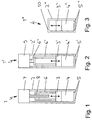
- the peculiarity of the piston dispensing device 1 ' is that the drive of the piston rod 6 'by a pneumatic Drive 9 takes place, indirectly via an additional rod 6 "acts on the piston rod 6 '.
- Figure 3 shows a further embodiment of a Piston meter 1 '', which also largely with the piston dispenser described above and shown in Figure 1 matches, so as to avoid References to the above description is referenced and in the following for corresponding components corresponding reference numerals used to distinguish only are provided with two dashes.
- the peculiarity of this embodiment is that provided for driving the metering piston 3 "no piston rod is.
- the dosing cylinder 2 '' at its top one Inlet or outlet 10 for a drive medium which in the area within the metering cylinder 2 "above the metering piston 3 "can be pressed to the metering piston 3" axially move.
- the invention is not limited to those described above Embodiments limited. Rather, a variety Variants and variations conceivable, also from use the idea of the invention and therefore in the Protection range fall.
- a typical example of a meaningful use of here is the use as a dosing Paint container in a supply system for material supply an electrostatic coating apparatus in which the Coating material, preferably by means of pushed Pig first with a predetermined volume by a first line passed into the paint container and then through a second line from the ink container is further promoted, for example corresponding to that described in EP 1 314 483 A2 A / B procedure and system.
- the subsidized material can from the piston drive during emptying or even during filling of the paint container are dosed.
- the device in a be used such supply system.
Landscapes
- Engineering & Computer Science (AREA)
- Mechanical Engineering (AREA)
- General Engineering & Computer Science (AREA)
- Reciprocating Pumps (AREA)
Abstract
Description
Die Erfindung betrifft eine Vorrichtung zum Dosieren oder Fördern
eines Fördermediums, insbesondere zum Dosieren von Beschichtungsmaterial
in einer Beschichtungsanlage, gemäß dem
Oberbegriff des Anspruchs 1.The invention relates to a device for dosing or conveying
a conveying medium, in particular for dosing coating material
in a coating plant, according to
Preamble of
In Beschichtungsanlagen zur Beschichtung von Werkstückoberflächen, wie beispielsweise Kraftfahrzeugkarosserieteilen, mit einem Beschichtungsmaterial, wie beispielsweise einem Lack, werden Dosiervorrichtungen eingesetzt, um das Beschichtungsmittel zu dosieren.In coating systems for coating work piece surfaces, such as automotive body panels, with a Coating material, such as a paint, are Dosing devices used to the coating agent to dose.
Es ist beispielsweise aus EP 0 640 017 B1 bekannt, derartige Dosiervorrichtungen als Kolbendosierer auszuführen, wobei ein Dosierkolben in einem Dosierzylinder axial bewegt wird, um das Beschichtungsmittel zu dosieren. Hierbei befindet sich das zu dosierende Beschichtungsmittel in dem Dosierzylinder auf der einen Seite des Dosierkolbens und kann von dem Dosierkolben aus dem Dosierzylinder heraus gedrückt werden. Der Antrieb des Dosierkolbens kann mechanisch über einen Spindelantrieb und eine Kolbenstange erfolgen, die auf den Dosierkolben wirkt.It is known, for example, from EP 0 640 017 B1, such To perform dosing as a piston dispenser, wherein a Dosing is moved axially in a metering cylinder to the Dose coating agent. This is the case dosing coating in the dosing on the one side of the metering and can from the metering pushed out of the dosing cylinder. The drive of the dosing piston can mechanically via a spindle drive and a Piston rod done, which acts on the metering piston.
Es ist weiterhin bekannt, den Dosierzylinder und die Kolbenstange bei einem derartigen Kolbendosierer aus einem elektrisch nicht leitfähigen Werkstoff zu fertigen, um eine Dosierung von Beschichtungsmittel zu ermöglichen, das elektrisch auf eine Hochspannung aufgeladen wurde.It is also known, the dosing and the piston rod in such a piston dispenser from an electric non-conductive material to produce a dosage of To allow coating agent, the electrically on a High voltage was charged.
Nachteilig an derartigen bekannten Dosiervorrichtungen ist die Tatsache, dass die Dosiergenauigkeit vor allem bei schnellen Sollwertänderungen der Dosiermenge und bei großen Förderdrücken unbefriedigend ist. A disadvantage of such known metering devices is the Fact that the dosing accuracy especially at fast Setpoint changes of the dosing quantity and at high delivery pressures is unsatisfactory.
Der Erfindung liegt somit die Aufgabe zugrunde, bei den vorstehend beschriebenen bekannten Dosiervorrichtungen die Dosiergenauigkeit insbesondere bei großen Förderdrücken und bei schnellen Sollwertänderungen der Dosiermenge zu verbessern.The invention is therefore based on the object in the above described known metering the dosing accuracy especially at high delivery pressures and fast To improve setpoint changes of the dosing quantity.
Diese Aufgabe wird, ausgehend von der eingangs beschriebenen
bekannten Dosiervorrichtung gemäß dem Oberbegriff des Anspruchs
1, durch die kennzeichnenden Merkmale des Anspruchs 1 gelöst.This task is based on the above-described
known metering device according to the preamble of the
Die Erfindung beruht auf der technischen Erkenntnis, dass die unbefriedigende Dosiergenauigkeit durch eine mechanische Nachgiebigkeit der elektrisch isolierenden Materialien der Dosiervorrichtung verursacht wird. So bestehen der Dosierzylinder und die Kolbenstange bei den bekannten Kolbendosiervorrichtungen aus einem elektrisch isolierenden Kunststoff, der sich insbesondere bei hohen Förderdrücken geringfügig verformt.The invention is based on the technical knowledge that the unsatisfactory dosing accuracy due to a mechanical compliance the electrically insulating materials of the metering device is caused. So exist the dosing cylinder and the piston rod in the known Kolbendosiervorrichtungen made of an electrically insulating plastic, in particular slightly deformed at high delivery pressures.
Die Verformung des zur elektrischen Isolierung verwendeten Kunststoffmaterials führt bei den bekannten Kolbendosiervorrichtungen zum einen zu einer Ausweitung und einer Längendehnung des Dosierzylinders, was mit Dosierfehlern verbunden ist.The deformation of the used for electrical insulation Plastic material leads in the known Kolbendosiervorrichtungen on the one hand to an expansion and a longitudinal expansion of the metering cylinder, which is associated with metering errors.
Zum anderen führt die Nachgiebigkeit des bei der bekannten Kolbendosiervorrichtung verwendeten Kunststoffmaterials zu einer Stauchung bzw. einer Dehnung der Kolbenstange, was ebenfalls mit Dosierfehlern verbunden ist.On the other hand leads to the flexibility of the known piston metering device used plastic material to a Compression or expansion of the piston rod, which also associated with dosing errors.
Die Erfindung umfasst deshalb die allgemeine technische Lehre, anstelle des herkömmlicherweise verwendeten Kunststoffes ein Material zu verwenden, das bei einem ausreichenden elektrischen Isolationsvermögen hinreichend starr ist, um die vorstehend beschriebenen Dosierfehler zu vermeiden. The invention therefore comprises the general technical teaching, in place of the conventionally used plastic Use material that is at a sufficient electrical Insulation capacity is sufficiently rigid to those described above Avoid dosing errors.
Vorzugsweise wird hierbei anstelle des herkömmlicherweise verwendeten Kunststoffes ein Material verwendet, das nicht nur elektrisch isolierend und hinreichend starr ist, sondern auch eine hohe mechanische Verschleißfestigkeit aufweist.Preferably, this is used instead of the conventionally used Plastic uses a material that is not just electrical Insulating and sufficiently rigid, but also has a high mechanical wear resistance.
Vorzugsweise wird deshalb ein elektrisch isolierendes Material verwendet, das ein Zugelastizitätsmodul und/oder ein Biegeelastizitätsmodul aufweist, das größer als 10 GPa ist. Derartig starre Werkstoffe verformen sich im Betrieb einer Dosiervorrichtung nicht nennenswert, wodurch die Dosiergenauigkeit erhöht wird.Preferably, therefore, an electrically insulating material that uses a tensile modulus and / or a flexural modulus which is greater than 10 GPa. Such rigid materials deform during operation of a dosing device not appreciably, whereby the dosing accuracy increases becomes.
Vorzugsweise liegt das Zugelastizitätsmodul bzw. das Biegeelastizitätsmodul des verwendeten Werkstoffs sogar über 100, 200 oder sogar 300 GPa, um auch bei großen Förderdrücken Verformungen und daraus resultierende Dosierfehler zu vermeiden.Preferably, the tensile elastic modulus or the bending elastic modulus lies of the material used even more than 100, 200 or even 300 GPa, even at high delivery pressures deformations and to avoid resulting dosing errors.
Das elektrisch isolierende und starre Material der mechanischen Bauteile der Dosier- bzw. Fördervorrichtung weist hierbei vorzugsweise einen spezifischen elektrischen Widerstand auf, der größer als 104 Ohm·cm ist, wobei beliebige Werte oberhalb dieses Grenzwertes möglich sind.The electrically insulating and rigid material of the mechanical components of the metering or conveying device in this case preferably has a specific electrical resistance which is greater than 10 4 ohm cm, with any values above this limit are possible.
Besonders geeignet ist als elektrisch isolierendes Material ein keramisches Material oder ein Silikat, da diese Werkstoffe einen großen Elastizitätsmodul aufweisen.Particularly suitable as an electrically insulating material ceramic material or a silicate, since these materials have a have a high modulus of elasticity.
Vorzugsweise wird hierbei ein oxidkeramisches Material verwendet, da Oxidkeramiken eine sehr geringe elektrische Leitfähigkeit haben. Beispielsweise können Al2O3, MgO, ZrO2, Al2TiO5, Steatit oder Cordierit allein oder in beliebiger Kombination untereinander verwendet werden. Vorteilhaft an oxidkeramischen Materialien besteht in der Kombination einer großen mechanischen Steifigkeit mit einem guten elektrischen Isolationsvermögen bei hoher mechanischer Verschleißbeständigkeit. Preferably, an oxide-ceramic material is used here since oxide ceramics have a very low electrical conductivity. For example, Al 2 O 3 , MgO, ZrO 2 , Al 2 TiO 5 , steatite or cordierite may be used alone or in any combination with each other. An advantage of oxide-ceramic materials is the combination of a high mechanical rigidity with a good electrical insulation capacity with high mechanical wear resistance.
Es ist jedoch auch möglich, ein nicht-oxidkeramisches Material zu verwenden, wie beispielsweise SSiC, SiC, SSN, RBSN oder B4C, wobei beliebige Kombinationen dieser Materialien möglich sind.However, it is also possible to use a non-oxide ceramic material such as SSiC, SiC, SSN, RBSN or B 4 C, and any combinations of these materials are possible.
In einer bevorzugten Ausführungsform der Erfindung weist die Dosiervorrichtung einen Dosierzylinder und einen Dosierkolben auf, der in dem Dosierzylinder verschiebbar gelagert ist, wobei der Dosierzyinder und/oder der Dosierkolben mindestens teilweise aus dem vorstehend beschriebenen elektrisch isolierenden und starren Material bestehen.In a preferred embodiment of the invention, the Metering a metering cylinder and a metering piston on, which is slidably mounted in the metering cylinder, wherein the Dosierzyinder and / or the metering piston at least partially from the above-described electrically insulating and consist of rigid material.
Der mechanische Antrieb des Dosierkolbens kann beispielsweise durch eine Kolbenstange erfolgen, die ebenfalls aus dem vorstehend beschriebenen elektrisch isolierenden und starren Material bestehen kann. Beispielsweise kann die Kolbenstange mit einem elektrischen Antriebsmotor verbunden sind, um die Kolbenstange anzusteuern. Es ist jedoch alternativ auch möglich, dass die Kolbenstange mit einem Hydraulikantrieb oder einem Pneumatikantrieb verbunden ist.The mechanical drive of the metering piston, for example be done by a piston rod, which also from the above described electrically insulating and rigid material can exist. For example, the piston rod with a electric drive motor are connected to the piston rod head for. However, it is alternatively possible that the Piston rod with a hydraulic drive or a pneumatic drive connected is.
Beim Einsatz der erfindungsgemäßen Kolbendosiervorrichtung in einer Beschichtungsanlage liegen die Antriebsseite und die Auslass- bzw. Ansaugseite der Kolbendosiervorrichtung unter Umständen auf einem unterschiedlichen elektrischen Potential, so dass eine elektrische Isolation zwischen der Ein- bzw. Auslassseite der Kolbendosiervorrichtung einerseits und der Antriebsseite der Kolbendosiervorrichtung andererseits erforderlich ist. Diese elektrische Isolation wird vorzugsweise dadurch erreicht, dass die Kolbenstange und der Zylinder aus einem elektrisch isolierenden Material bestehen, das jedoch mechanisch hinreichend starr ist, um Dosierfehler weitgehend zu vermeiden. Hierbei bildet also die Baulänge der Kolbendosiervorrichtung in der Zylinderachse eine Isolierstrecke. Zur Erreichung des erforderlichen Isolationsvermögens können die Kolbenstange und der Dosierzylinder aus den vorstehend beschriebenen Werkstoffen bestehen.When using the piston metering device according to the invention in In a coating plant, the drive side and the outlet or suction side of Kolbendosiervorrichtung under circumstances at a different electrical potential, like that that an electrical insulation between the inlet and outlet side the Kolbendosiervorrichtung one hand and the drive side the Kolbendosiervorrichtung other hand required is. This electrical isolation is preferably achieved by that the piston rod and the cylinder are made of an electric insulating material, but mechanically is sufficiently rigid to largely avoid dosing errors. In this case, so the length of the piston metering device forms in the cylinder axis an insulating section. To achieve the required Isolation capacity can be the piston rod and the dosing of the materials described above consist.
Darüber hinaus ist es auch möglich, auf eine Kolbenstange zu verzichten, indem der Dosierkolben direkt mit einem Antriebsmedium beaufschlagt wird. Hierbei weist der Dosierzylinder auf einer Seite des Dosierkolbens vorzugsweise einen ersten Ein- bzw. Auslass für das zu fördernde Medium und auf der anderen Seite des Dosierkolbens einen zweiten Ein- bzw. Auslass für ein Antriebsmedium auf. Die Stellung bzw. die Bewegung des Dosierkolbens kann dann gesteuert werden, indem der Druck in dem Antriebsmedium entsprechend eingestellt wird.In addition, it is also possible to use a piston rod dispense by the dosing directly with a drive medium is charged. In this case, the metering cylinder one side of the metering piston preferably has a first or outlet for the medium to be promoted and on the other Side of the metering a second inlet or outlet for a Drive medium on. The position or movement of the dosing piston can then be controlled by the pressure in the drive medium is adjusted accordingly.
Eine Variante der Erfindung sieht bei einer Kolbendosiervorrichtung vor, dass der Dosierzylinder einen Innenquerschnitt aufweist, der von einer Kreisform abweicht, während der Dosierkolben einen entsprechend formangepassten Außenquerschnitt aufweist, so dass der Dosierkolben in dem Dosierzylinder axial verschiebbar ist. Eine derartige, beispielsweise ovale Formgebung des Dosierzylinders und des Dosierkolbens verhindert eine Verdrehung des Dosierkolbens relativ zu dem Dosierzylinder, so dass auf eine separate Verdrehsicherung verzichtet werden kann.A variant of the invention provides for a piston metering device before, that the metering cylinder has an internal cross section has, which deviates from a circular shape, while the metering piston has a corresponding shape-adapted outer cross section, so that the metering in the metering cylinder axially is displaceable. Such, for example, oval shape the dosing cylinder and the dosing prevents a Rotation of the metering relative to the metering cylinder, so that can be dispensed with a separate anti-rotation device.
Andere vorteilhafte Weiterbildungen der Erfindung sind in Unteransprüchen gekennzeichnet oder werden nachstehend zusammen mit der Beschreibung der bevorzugten Ausführungsbeispiele der Erfindung anhand der Figuren näher erläutert. Es zeigen:
Figur 1- eine Kolbendosiervorrichtung mit einem Spindelantrieb des Dosierkolbens zum Einsatz in einer Beschichtungsanlage,
Figur 2- eine erfindungsgemäße Kolbendosiervorrichtung mit einem pneumatischen Antrieb des Dosierkolbens sowie
Figur 3- eine Kolbendosiervorrichtung mit einem hydraulischen Antrieb des Dosierkolbens.
- FIG. 1
- a piston metering device with a spindle drive of the metering piston for use in a coating installation,
- FIG. 2
- a piston metering device according to the invention with a pneumatic drive of the metering piston and
- FIG. 3
- a piston metering device with a hydraulic drive of the metering piston.
Die Querschnittsansicht in Figur 1 zeigt schematisch eine Kolbendosiervorrichtung
1 zum Einsatz in einer Beschichtungsanlage
zum Beschichten von Kraftfahrzeugkarosserieteilen mit einem
Lack, wobei derartige Beschichtungsanlagen an sich bekannt sind
und deshalb im Folgenden nicht weiter beschrieben werden.The cross-sectional view in Figure 1 shows schematically a
Die Kolbendosiervorrichtung 1 weist einen Dosierzylinder 2 auf,
in dem ein Dosierkolben 3 axial verschiebbar gelagert ist, wobei
der Dosierkolben 3 den Innenquerschnitt des Dosierzylinders
2 im Wesentlichen vollständig ausfüllt.The
Innerhalb des Dosierzylinders 2 befindet sich unterhalb des Dosierkolbens
3 ein Dosiervolumen 4, das im Betrieb mit einem Beschichtungsmittel
gefüllt ist, wobei das Beschichtungsmittel 4
aus dem Dosiervolumen durch eine Öffnung 5 in der unteren
Stirnseite des Dosierzylinders 2 heraus gedrückt werden kann.Within the
Der Antrieb des Dosierkolbens 3 erfolgt hierbei durch eine Kolbenstange
6, die an der Oberseite des Dosierkolbens 3 befestigt
ist und durch einen Antriebsmotor 7 mittels einer Antriebsspindel
8 axial verschoben wird. Eine Drehung der Antriebsspindel 8
führt also zu einer entsprechenden Axialverschiebung des Dosierkolbens
3 und damit zu einer entsprechenden Dosierung des
Beschichtungsmittels.The drive of the
Die Kolbenstange 6 und der Dosierzylinder 2 bestehen hierbei
aus einem elektrisch isolierenden Material, um eine Dosierung
eines unter Hochspannung stehenden Beschichtungsmaterials zu
ermöglichen. In diesem Ausführungsbeispiel wird hierzu Al2O3
verwendet, das ein Elastizitätsmodul von 360...410 GPa aufweist
und somit wesentlich starrer ist als der üblicherweise verwendete
Kunststoff. Die Verwendung eines derartigen oxidkeramischen
Materials für den Dosierzylinder 2 und die Kolbenstange 6
kombiniert vorteilhaft eine hervorragende elektrische Isolation
mit einer großen mechanischen Festigkeit.The
Das in Figur 2 dargestellte Ausführungsbeispiel einer Kolbendosiervorrichtung 1' stimmt weitgehend mit der vorstehend beschriebenen und in Figur 1 dargestellten Kolbendosiervorrichtung 1 überein, so dass zur Vermeidung von Wiederholungen auf die vorstehende Beschreibung verwiesen wird und für entsprechende Bauteile entsprechende Bezugszeichen verwendet werden, die zur Unterscheidung lediglich mit einem Strich versehen sind.The embodiment shown in Figure 2 a Kolbendosiervorrichtung 1 'is largely the same as described above and in Fig. 1 Kolbendosiervorrichtung shown 1 match, allowing to avoid repetition the above description is referenced and for corresponding Components corresponding reference numerals are used, for the sake of distinction only with a dash are.
Die Besonderheit der Kolbendosiervorrichtung 1' besteht darin,
dass der Antrieb der Kolbenstange 6' durch einen pneumatischen
Antrieb 9 erfolgt, der indirekt über eine zusätzliche Stange
6" auf die Kolbenstange 6' wirkt.The peculiarity of the piston dispensing device 1 'is
that the drive of the piston rod 6 'by a
Schließlich zeigt Figur 3 ein weiteres Ausführungsbeispiel einer Kolbendosiervorrichtung 1'', das ebenfalls weitgehend mit der vorstehend beschriebenen und in Figur 1 dargestellten Kolbendosiervorrichtung übereinstimmt, so dass zur Vermeidung von Wiederholungen auf die vorstehende Beschreibung verwiesen wird und im Folgenden für entsprechende Bauteile entsprechende Bezugszeichen verwendet werden, die zur Unterscheidung lediglich mit zwei Strichen versehen sind.Finally, Figure 3 shows a further embodiment of a Piston meter 1 '', which also largely with the piston dispenser described above and shown in Figure 1 matches, so as to avoid References to the above description is referenced and in the following for corresponding components corresponding reference numerals used to distinguish only are provided with two dashes.
Die Besonderheit dieses Ausführungsbeispiels besteht darin,
dass zum Antrieb des Dosierkolbens 3" keine Kolbenstange vorgesehen
ist.The peculiarity of this embodiment is
that provided for driving the
Vielmehr weist der Dosierzylinder 2'' an seiner Oberseite einen
Ein- bzw. Auslass 10 für ein Antriebsmedium auf, das in den Bereich
innerhalb des Dosierzylinders 2" oberhalb des Dosierkolbens
3" gepresst werden kann, um den Dosierkolben 3" axial zu
bewegen. Die Bewegung bzw. Stellung des Dosierkolbens 3'' lässt
sich also durch den Druck in dem Raum oberhalb des Dosierkolbens
3'' steuern.Rather, the dosing cylinder 2 '' at its top one
Inlet or
Die Erfindung ist nicht auf die vorstehend beschriebenen bevorzugten Ausführungsbeispiele beschränkt. Vielmehr ist eine Vielzahl von Varianten und Abwandlungen denkbar, die ebenfalls von dem Erfindungsgedanken Gebrauch machen und deshalb in den Schutzbereich fallen.The invention is not limited to those described above Embodiments limited. Rather, a variety Variants and variations conceivable, also from use the idea of the invention and therefore in the Protection range fall.
Ein typisches Beispiel für eine sinnvolle Verwendung der hier
beschriebenen Vorrichtung ist die Verwendung als dosierender
Farbbehälter in einem Versorgungssystem zur Materialversorgung
einer elektrostatischen Beschichtungsvorrichtung, in dem das
Beschichtungsmaterial vorzugsweise mit Hilfe von geschobenen
Molchen zunächst mit einem vorbestimmten Volumen durch eine
erste Leitung in den Farbbehälter geleitet und dann durch eine
zweite Leitung aus dem Farbbehälter weitergefördert wird, beispielsweise
entsprechend dem in der EP 1 314 483 A2 beschriebenen
A/B-Verfahren und System. Das geförderte Material kann von
dem Kolbenantrieb bei der Entleerung oder auch bei der Befüllung
des Farbbehälters dosiert werden. Auch zum Fördern und/oder
Dosieren einer Spülflüssigkeit kann die Vorrichtung in einem
derartigen Versorgungssystem verwendet werden.A typical example of a meaningful use of here
The device described is the use as a dosing
Paint container in a supply system for material supply
an electrostatic coating apparatus in which the
Coating material, preferably by means of pushed
Pig first with a predetermined volume by a
first line passed into the paint container and then through a
second line from the ink container is further promoted, for example
corresponding to that described in
Claims (14)
Applications Claiming Priority (2)
| Application Number | Priority Date | Filing Date | Title |
|---|---|---|---|
| DE10233633 | 2002-07-24 | ||
| DE10233633A DE10233633B4 (en) | 2002-07-24 | 2002-07-24 | Device for dosing or conveying a high-voltage potential charged coating agent in a coating system |
Publications (2)
| Publication Number | Publication Date |
|---|---|
| EP1384885A1 true EP1384885A1 (en) | 2004-01-28 |
| EP1384885B1 EP1384885B1 (en) | 2005-10-12 |
Family
ID=29796549
Family Applications (1)
| Application Number | Title | Priority Date | Filing Date |
|---|---|---|---|
| EP03016338A Expired - Lifetime EP1384885B1 (en) | 2002-07-24 | 2003-07-18 | Piston device for dosing or delivering a fluid conveying medium |
Country Status (4)
| Country | Link |
|---|---|
| EP (1) | EP1384885B1 (en) |
| AT (1) | ATE306615T1 (en) |
| DE (1) | DE10233633B4 (en) |
| ES (1) | ES2248688T3 (en) |
Cited By (5)
| Publication number | Priority date | Publication date | Assignee | Title |
|---|---|---|---|---|
| DE102004058053A1 (en) * | 2004-12-01 | 2006-06-14 | Dürr Systems GmbH | Method and piston dispenser for the metered supply of material to a coating device |
| US7908994B2 (en) | 2005-10-21 | 2011-03-22 | Duerr Systems, Inc. | Automatically steered coating machine also a container for the coating material |
| US8020784B2 (en) | 2005-10-07 | 2011-09-20 | Durr Systems Inc. | Coating material supply installation and associated operating procedure |
| US8333164B2 (en) | 2006-12-12 | 2012-12-18 | Duerr Systems, Gmbh | Coating apparatus comprising a metering device |
| US8418647B2 (en) | 2005-10-21 | 2013-04-16 | Dürr Systems Inc. | Procedure and piston type metering devices for the metered material supply for a coating device |
Families Citing this family (5)
| Publication number | Priority date | Publication date | Assignee | Title |
|---|---|---|---|---|
| ES2685244T3 (en) | 2005-10-07 | 2018-10-08 | Dürr Systems Ag | Coating agent supply device and corresponding operating procedure |
| DE102006038563A1 (en) * | 2006-08-17 | 2008-04-30 | Eisenmann Lacktechnik Gmbh & Co. Kg | Device for conveying an electrically conductive fluid coating material |
| DE102007029195A1 (en) | 2007-06-25 | 2009-02-19 | Dürr Systems GmbH | Coating device for serially coating workpieces with different shades comprises a separate color changer containing color valves to which are connected color lines for the coating material |
| DE102006058562A1 (en) | 2006-12-12 | 2008-08-14 | Dürr Systems GmbH | Coating device for serially coating workpieces with different shades comprises a separate color changer containing color valves to which are connected color lines for the coating material |
| DE102017111823A1 (en) * | 2017-05-30 | 2018-12-06 | Eisenmann Se | Isolation device and coating system hereby |
Citations (7)
| Publication number | Priority date | Publication date | Assignee | Title |
|---|---|---|---|---|
| GB1365292A (en) * | 1971-10-01 | 1974-08-29 | Birmingham Small Arms Co Ltd | Pumps |
| EP0270130A2 (en) * | 1986-12-05 | 1988-06-08 | Saphirwerk Industrieprodukte AG | Precision dosing pump for liquids |
| DE4108105A1 (en) * | 1991-03-13 | 1992-09-17 | Kaercher Gmbh & Co Alfred | Piston for HP cleaning system pump - has sections bridged by flexible, compressible, annular clamps |
| JPH0518354A (en) * | 1991-07-09 | 1993-01-26 | Kubota Corp | Ceramic pump for melted nonferrous metal |
| EP0610708A1 (en) * | 1993-02-09 | 1994-08-17 | MAUCHER, Eberhard | Dosing pump |
| EP0640017A1 (en) * | 1992-05-15 | 1995-03-01 | Abb Trallfa Robot A/S | Paint dosage device for program controlled spray painting system |
| US6126404A (en) * | 1997-06-09 | 2000-10-03 | Saphirwerk Industrieprodukte Ag | Apparatus for the metered delivery of fluids |
Family Cites Families (2)
| Publication number | Priority date | Publication date | Assignee | Title |
|---|---|---|---|---|
| DE3741968C3 (en) * | 1987-12-11 | 2002-11-14 | Huebers Verfahrenstech | metering |
| DE4303463C2 (en) * | 1993-02-06 | 1996-04-04 | Abb Patent Gmbh | Conveyor |
-
2002
- 2002-07-24 DE DE10233633A patent/DE10233633B4/en not_active Expired - Lifetime
-
2003
- 2003-07-18 AT AT03016338T patent/ATE306615T1/en not_active IP Right Cessation
- 2003-07-18 ES ES03016338T patent/ES2248688T3/en not_active Expired - Lifetime
- 2003-07-18 EP EP03016338A patent/EP1384885B1/en not_active Expired - Lifetime
Patent Citations (7)
| Publication number | Priority date | Publication date | Assignee | Title |
|---|---|---|---|---|
| GB1365292A (en) * | 1971-10-01 | 1974-08-29 | Birmingham Small Arms Co Ltd | Pumps |
| EP0270130A2 (en) * | 1986-12-05 | 1988-06-08 | Saphirwerk Industrieprodukte AG | Precision dosing pump for liquids |
| DE4108105A1 (en) * | 1991-03-13 | 1992-09-17 | Kaercher Gmbh & Co Alfred | Piston for HP cleaning system pump - has sections bridged by flexible, compressible, annular clamps |
| JPH0518354A (en) * | 1991-07-09 | 1993-01-26 | Kubota Corp | Ceramic pump for melted nonferrous metal |
| EP0640017A1 (en) * | 1992-05-15 | 1995-03-01 | Abb Trallfa Robot A/S | Paint dosage device for program controlled spray painting system |
| EP0610708A1 (en) * | 1993-02-09 | 1994-08-17 | MAUCHER, Eberhard | Dosing pump |
| US6126404A (en) * | 1997-06-09 | 2000-10-03 | Saphirwerk Industrieprodukte Ag | Apparatus for the metered delivery of fluids |
Non-Patent Citations (1)
| Title |
|---|
| PATENT ABSTRACTS OF JAPAN vol. 017, no. 294 (M - 1424) 7 June 1993 (1993-06-07) * |
Cited By (7)
| Publication number | Priority date | Publication date | Assignee | Title |
|---|---|---|---|---|
| DE102004058053A1 (en) * | 2004-12-01 | 2006-06-14 | Dürr Systems GmbH | Method and piston dispenser for the metered supply of material to a coating device |
| DE102004058053B4 (en) * | 2004-12-01 | 2006-12-28 | Dürr Systems GmbH | Method and piston dispenser for the metered supply of material to a coating device |
| US8020784B2 (en) | 2005-10-07 | 2011-09-20 | Durr Systems Inc. | Coating material supply installation and associated operating procedure |
| US7908994B2 (en) | 2005-10-21 | 2011-03-22 | Duerr Systems, Inc. | Automatically steered coating machine also a container for the coating material |
| US8418647B2 (en) | 2005-10-21 | 2013-04-16 | Dürr Systems Inc. | Procedure and piston type metering devices for the metered material supply for a coating device |
| US8333164B2 (en) | 2006-12-12 | 2012-12-18 | Duerr Systems, Gmbh | Coating apparatus comprising a metering device |
| EP2853312A2 (en) | 2006-12-12 | 2015-04-01 | Dürr Systems GmbH | ICC metering |
Also Published As
| Publication number | Publication date |
|---|---|
| DE10233633B4 (en) | 2005-09-01 |
| EP1384885B1 (en) | 2005-10-12 |
| DE10233633A1 (en) | 2004-02-12 |
| ATE306615T1 (en) | 2005-10-15 |
| ES2248688T3 (en) | 2006-03-16 |
Similar Documents
| Publication | Publication Date | Title |
|---|---|---|
| DE69906519T2 (en) | DEVICE FOR DROP DROPS | |
| EP1213529B1 (en) | Lubricant dispenser | |
| EP1384885B1 (en) | Piston device for dosing or delivering a fluid conveying medium | |
| CH675216A5 (en) | ||
| WO1991010062A1 (en) | Electrically controlled fuel injection pump for internal combustion engines, especially pump nozzle | |
| DE19610072A1 (en) | Precision dispensing pump for viscous materials | |
| DE19610588B4 (en) | Coating machine with replaceable container | |
| EP0064209B1 (en) | Apparatus for the manufacture of a homogeneous or cellular plastics material that forms a reaction mixture from two liquid reactive components | |
| EP1395371A1 (en) | Expression device for a cartridge comprising two chambers arranged concentrically to each other | |
| DE2933512A1 (en) | SAMPLE INJECTION VALVE | |
| DE2507387A1 (en) | PIEZOELECTRIC HIGH VOLTAGE ARRANGEMENT | |
| DE3440417C1 (en) | Adhesive application device, in particular for the leather goods and shoe industry | |
| DE102023106650A1 (en) | Tensionable electric heater | |
| DE102006007316B4 (en) | Endodontic instrument | |
| DE2556169B2 (en) | Impulse-controlled drop spray device | |
| EP0226070A2 (en) | Pump arrangement for delivering measured quantities of at least two components | |
| EP4268973A2 (en) | Atomizing nozzle system | |
| DE3103061A1 (en) | Piezoelectric actuator | |
| DE102005018306A1 (en) | Drive and/or dose metering module for injection device e.g. injection pen, includes rotating element having stop and cooperating stop disposed transversely to the direction of rotation | |
| DE102020121665A1 (en) | Dosing system with a syringe and a syringe pump | |
| EP0898085B1 (en) | Pressurised-fluid motor for electrorheological fluids | |
| DE1270741B (en) | Piston pump for a die casting device | |
| EP0628390B1 (en) | Proportioning and conveyer pump and employment of such a pump for making moulded resin bodies | |
| DE3419058A1 (en) | SPRAY GUN WITH DAMPING DEVICE | |
| DE4107479A1 (en) | Dosing arrangement for liquids or pastes for medical media - has piston movable axially in chamber with dispensing needle tip, electric motor driving piston rod via transmission |
Legal Events
| Date | Code | Title | Description |
|---|---|---|---|
| PUAI | Public reference made under article 153(3) epc to a published international application that has entered the european phase |
Free format text: ORIGINAL CODE: 0009012 |
|
| AK | Designated contracting states |
Kind code of ref document: A1 Designated state(s): AT BE BG CH CY CZ DE DK EE ES FI FR GB GR HU IE IT LI LU MC NL PT RO SE SI SK TR |
|
| AX | Request for extension of the european patent |
Extension state: AL LT LV MK |
|
| 17P | Request for examination filed |
Effective date: 20040209 |
|
| 17Q | First examination report despatched |
Effective date: 20040617 |
|
| AKX | Designation fees paid |
Designated state(s): AT BE BG CH CY CZ DE DK EE ES FI FR GB GR HU IE IT LI LU MC NL PT RO SE SI SK TR |
|
| GRAP | Despatch of communication of intention to grant a patent |
Free format text: ORIGINAL CODE: EPIDOSNIGR1 |
|
| RTI1 | Title (correction) |
Free format text: PISTON DEVICE FOR DOSING OR DELIVERING A FLUID CONVEYING MEDIUM |
|
| GRAS | Grant fee paid |
Free format text: ORIGINAL CODE: EPIDOSNIGR3 |
|
| RBV | Designated contracting states (corrected) |
Designated state(s): AT BE BG CH CY CZ DK EE ES FI FR GB GR HU IE IT LI LU MC NL PT RO SE SI SK TR |
|
| REG | Reference to a national code |
Ref country code: DE Ref legal event code: 8566 |
|
| GRAA | (expected) grant |
Free format text: ORIGINAL CODE: 0009210 |
|
| RAP1 | Party data changed (applicant data changed or rights of an application transferred) |
Owner name: DUERR SYSTEMS GMBH |
|
| RBV | Designated contracting states (corrected) |
Designated state(s): AT BE BG CH CY CZ DK EE ES FI FR GB GR HU IE IT LI LU MC NL PT RO SE SI SK TR |
|
| AK | Designated contracting states |
Kind code of ref document: B1 Designated state(s): AT BE BG CH CY CZ DK EE ES FI FR GB GR HU IE IT LI LU MC NL PT RO SE SI SK TR |
|
| PG25 | Lapsed in a contracting state [announced via postgrant information from national office to epo] |
Ref country code: SK Free format text: LAPSE BECAUSE OF FAILURE TO SUBMIT A TRANSLATION OF THE DESCRIPTION OR TO PAY THE FEE WITHIN THE PRESCRIBED TIME-LIMIT Effective date: 20051012 Ref country code: SI Free format text: LAPSE BECAUSE OF FAILURE TO SUBMIT A TRANSLATION OF THE DESCRIPTION OR TO PAY THE FEE WITHIN THE PRESCRIBED TIME-LIMIT Effective date: 20051012 Ref country code: RO Free format text: LAPSE BECAUSE OF FAILURE TO SUBMIT A TRANSLATION OF THE DESCRIPTION OR TO PAY THE FEE WITHIN THE PRESCRIBED TIME-LIMIT Effective date: 20051012 Ref country code: IE Free format text: LAPSE BECAUSE OF FAILURE TO SUBMIT A TRANSLATION OF THE DESCRIPTION OR TO PAY THE FEE WITHIN THE PRESCRIBED TIME-LIMIT Effective date: 20051012 Ref country code: FI Free format text: LAPSE BECAUSE OF FAILURE TO SUBMIT A TRANSLATION OF THE DESCRIPTION OR TO PAY THE FEE WITHIN THE PRESCRIBED TIME-LIMIT Effective date: 20051012 Ref country code: CZ Free format text: LAPSE BECAUSE OF FAILURE TO SUBMIT A TRANSLATION OF THE DESCRIPTION OR TO PAY THE FEE WITHIN THE PRESCRIBED TIME-LIMIT Effective date: 20051012 |
|
| REG | Reference to a national code |
Ref country code: GB Ref legal event code: FG4D Free format text: NOT ENGLISH |
|
| REG | Reference to a national code |
Ref country code: CH Ref legal event code: EP |
|
| REG | Reference to a national code |
Ref country code: IE Ref legal event code: FG4D Free format text: LANGUAGE OF EP DOCUMENT: GERMAN |
|
| REG | Reference to a national code |
Ref country code: SE Ref legal event code: TRGR |
|
| PG25 | Lapsed in a contracting state [announced via postgrant information from national office to epo] |
Ref country code: GR Free format text: LAPSE BECAUSE OF FAILURE TO SUBMIT A TRANSLATION OF THE DESCRIPTION OR TO PAY THE FEE WITHIN THE PRESCRIBED TIME-LIMIT Effective date: 20060112 Ref country code: DK Free format text: LAPSE BECAUSE OF FAILURE TO SUBMIT A TRANSLATION OF THE DESCRIPTION OR TO PAY THE FEE WITHIN THE PRESCRIBED TIME-LIMIT Effective date: 20060112 Ref country code: BG Free format text: LAPSE BECAUSE OF FAILURE TO SUBMIT A TRANSLATION OF THE DESCRIPTION OR TO PAY THE FEE WITHIN THE PRESCRIBED TIME-LIMIT Effective date: 20060112 |
|
| GBT | Gb: translation of ep patent filed (gb section 77(6)(a)/1977) |
Effective date: 20060111 |
|
| PG25 | Lapsed in a contracting state [announced via postgrant information from national office to epo] |
Ref country code: PT Free format text: LAPSE BECAUSE OF FAILURE TO SUBMIT A TRANSLATION OF THE DESCRIPTION OR TO PAY THE FEE WITHIN THE PRESCRIBED TIME-LIMIT Effective date: 20060313 |
|
| REG | Reference to a national code |
Ref country code: ES Ref legal event code: FG2A Ref document number: 2248688 Country of ref document: ES Kind code of ref document: T3 |
|
| PG25 | Lapsed in a contracting state [announced via postgrant information from national office to epo] |
Ref country code: HU Free format text: LAPSE BECAUSE OF FAILURE TO SUBMIT A TRANSLATION OF THE DESCRIPTION OR TO PAY THE FEE WITHIN THE PRESCRIBED TIME-LIMIT Effective date: 20060413 |
|
| REG | Reference to a national code |
Ref country code: IE Ref legal event code: FD4D |
|
| ET | Fr: translation filed | ||
| PG25 | Lapsed in a contracting state [announced via postgrant information from national office to epo] |
Ref country code: MC Free format text: LAPSE BECAUSE OF NON-PAYMENT OF DUE FEES Effective date: 20060731 |
|
| PLBE | No opposition filed within time limit |
Free format text: ORIGINAL CODE: 0009261 |
|
| STAA | Information on the status of an ep patent application or granted ep patent |
Free format text: STATUS: NO OPPOSITION FILED WITHIN TIME LIMIT |
|
| 26N | No opposition filed |
Effective date: 20060713 |
|
| PG25 | Lapsed in a contracting state [announced via postgrant information from national office to epo] |
Ref country code: AT Free format text: LAPSE BECAUSE OF NON-PAYMENT OF DUE FEES Effective date: 20060718 |
|
| REG | Reference to a national code |
Ref country code: CH Ref legal event code: PL |
|
| PG25 | Lapsed in a contracting state [announced via postgrant information from national office to epo] |
Ref country code: LI Free format text: LAPSE BECAUSE OF NON-PAYMENT OF DUE FEES Effective date: 20070731 Ref country code: CH Free format text: LAPSE BECAUSE OF NON-PAYMENT OF DUE FEES Effective date: 20070731 |
|
| PG25 | Lapsed in a contracting state [announced via postgrant information from national office to epo] |
Ref country code: EE Free format text: LAPSE BECAUSE OF FAILURE TO SUBMIT A TRANSLATION OF THE DESCRIPTION OR TO PAY THE FEE WITHIN THE PRESCRIBED TIME-LIMIT Effective date: 20051012 |
|
| PG25 | Lapsed in a contracting state [announced via postgrant information from national office to epo] |
Ref country code: TR Free format text: LAPSE BECAUSE OF FAILURE TO SUBMIT A TRANSLATION OF THE DESCRIPTION OR TO PAY THE FEE WITHIN THE PRESCRIBED TIME-LIMIT Effective date: 20051012 Ref country code: LU Free format text: LAPSE BECAUSE OF NON-PAYMENT OF DUE FEES Effective date: 20060718 |
|
| PG25 | Lapsed in a contracting state [announced via postgrant information from national office to epo] |
Ref country code: CY Free format text: LAPSE BECAUSE OF FAILURE TO SUBMIT A TRANSLATION OF THE DESCRIPTION OR TO PAY THE FEE WITHIN THE PRESCRIBED TIME-LIMIT Effective date: 20051012 |
|
| REG | Reference to a national code |
Ref country code: FR Ref legal event code: PLFP Year of fee payment: 14 |
|
| REG | Reference to a national code |
Ref country code: FR Ref legal event code: PLFP Year of fee payment: 15 |
|
| REG | Reference to a national code |
Ref country code: FR Ref legal event code: PLFP Year of fee payment: 16 |
|
| PGFP | Annual fee paid to national office [announced via postgrant information from national office to epo] |
Ref country code: NL Payment date: 20220720 Year of fee payment: 20 |
|
| PGFP | Annual fee paid to national office [announced via postgrant information from national office to epo] |
Ref country code: SE Payment date: 20220720 Year of fee payment: 20 Ref country code: IT Payment date: 20220726 Year of fee payment: 20 Ref country code: GB Payment date: 20220722 Year of fee payment: 20 Ref country code: ES Payment date: 20220921 Year of fee payment: 20 |
|
| PGFP | Annual fee paid to national office [announced via postgrant information from national office to epo] |
Ref country code: FR Payment date: 20220720 Year of fee payment: 20 Ref country code: BE Payment date: 20220720 Year of fee payment: 20 |
|
| P01 | Opt-out of the competence of the unified patent court (upc) registered |
Effective date: 20230512 |
|
| REG | Reference to a national code |
Ref country code: NL Ref legal event code: MK Effective date: 20230717 |
|
| REG | Reference to a national code |
Ref country code: ES Ref legal event code: FD2A Effective date: 20230727 |
|
| REG | Reference to a national code |
Ref country code: GB Ref legal event code: PE20 Expiry date: 20230717 |
|
| REG | Reference to a national code |
Ref country code: BE Ref legal event code: MK Effective date: 20230718 |
|
| REG | Reference to a national code |
Ref country code: SE Ref legal event code: EUG |
|
| PG25 | Lapsed in a contracting state [announced via postgrant information from national office to epo] |
Ref country code: GB Free format text: LAPSE BECAUSE OF EXPIRATION OF PROTECTION Effective date: 20230717 Ref country code: ES Free format text: LAPSE BECAUSE OF EXPIRATION OF PROTECTION Effective date: 20230719 |