EP1384831A1 - A flushing toilet - Google Patents
A flushing toilet Download PDFInfo
- Publication number
- EP1384831A1 EP1384831A1 EP02703481A EP02703481A EP1384831A1 EP 1384831 A1 EP1384831 A1 EP 1384831A1 EP 02703481 A EP02703481 A EP 02703481A EP 02703481 A EP02703481 A EP 02703481A EP 1384831 A1 EP1384831 A1 EP 1384831A1
- Authority
- EP
- European Patent Office
- Prior art keywords
- stool
- liquid
- pump
- urine
- pipe
- Prior art date
- Legal status (The legal status is an assumption and is not a legal conclusion. Google has not performed a legal analysis and makes no representation as to the accuracy of the status listed.)
- Withdrawn
Links
Images


Classifications
-
- A—HUMAN NECESSITIES
- A47—FURNITURE; DOMESTIC ARTICLES OR APPLIANCES; COFFEE MILLS; SPICE MILLS; SUCTION CLEANERS IN GENERAL
- A47K—SANITARY EQUIPMENT; ACCESSORIES THEREFOR, e.g. TOILET ACCESSORIES
- A47K11/00—Closets without flushing; Urinals without flushing; Chamber pots; Chairs with toilet conveniences or specially adapted for use with toilets
- A47K11/02—Dry closets, e.g. incinerator closets
-
- E—FIXED CONSTRUCTIONS
- E03—WATER SUPPLY; SEWERAGE
- E03D—WATER-CLOSETS OR URINALS WITH FLUSHING DEVICES; FLUSHING VALVES THEREFOR
- E03D5/00—Special constructions of flushing devices, e.g. closed flushing system
- E03D5/003—Grey water flushing systems
-
- E—FIXED CONSTRUCTIONS
- E03—WATER SUPPLY; SEWERAGE
- E03D—WATER-CLOSETS OR URINALS WITH FLUSHING DEVICES; FLUSHING VALVES THEREFOR
- E03D5/00—Special constructions of flushing devices, e.g. closed flushing system
- E03D5/016—Special constructions of flushing devices, e.g. closed flushing system with recirculation of bowl-cleaning fluid
-
- E—FIXED CONSTRUCTIONS
- E03—WATER SUPPLY; SEWERAGE
- E03D—WATER-CLOSETS OR URINALS WITH FLUSHING DEVICES; FLUSHING VALVES THEREFOR
- E03D9/00—Sanitary or other accessories for lavatories ; Devices for cleaning or disinfecting the toilet room or the toilet bowl; Devices for eliminating smells
- E03D9/10—Waste-disintegrating apparatus combined with the bowl
-
- Y—GENERAL TAGGING OF NEW TECHNOLOGICAL DEVELOPMENTS; GENERAL TAGGING OF CROSS-SECTIONAL TECHNOLOGIES SPANNING OVER SEVERAL SECTIONS OF THE IPC; TECHNICAL SUBJECTS COVERED BY FORMER USPC CROSS-REFERENCE ART COLLECTIONS [XRACs] AND DIGESTS
- Y02—TECHNOLOGIES OR APPLICATIONS FOR MITIGATION OR ADAPTATION AGAINST CLIMATE CHANGE
- Y02A—TECHNOLOGIES FOR ADAPTATION TO CLIMATE CHANGE
- Y02A50/00—TECHNOLOGIES FOR ADAPTATION TO CLIMATE CHANGE in human health protection, e.g. against extreme weather
- Y02A50/30—Against vector-borne diseases, e.g. mosquito-borne, fly-borne, tick-borne or waterborne diseases whose impact is exacerbated by climate change
Definitions
- the invention relates to processing unit in the field of water, drain water, waste water or mud residue processing. More particularly, the invention relates to a flushing lavatory used for stool and urine processing. Its main task is to use circulated flushing and stool crushing structure, urine collecting device, double pump flushing device for avoiding sediment accumulation and automatic urine and stool identification method and device to combine together so as to configure a no headwater flushing lavatory. It can only use the urine as flush liquid and realize the clean flushing, no bad smell from the sewage and controllable discharge. Users can finish common flushing and running without applying any control and operation on the lavatory.
- the invention is a new design with good applicability and big progress. It's suitable to be widely spread in the industry field.
- the main technical problem need to be solved in the invention is to overcome the defects of the prior flushing lavatory and provide a lavatory with new structure for the purpose of eliminating the disadvantage of using too much water of the stool crushing lavatory.
- the new lavatory can recycle the discharged flush liquid to flush the toilet pan and realize the effect of maximum water saving.
- the subsidiary technical problem need to be solved is to provide a flushing lavatory, which can collect the urine as flush liquid when the lavatory is in using.
- the lavatory not only has the function of urine collection, but also can finish the ordinary operation of flush, stool discharge or crush. It can utilize the waste offal to flush the lavatory and has the good effect of no water flushing.
- Another technical problem need to be solved in the invention is to provide a flushing lavatory, which has the automatic liquid medicine adding device.
- the environment protection liquid medicine in the medicine pot is conducted into the urine collecting box.
- the open and close of the pipe is controlled by the magnetic valve.
- the lavatory has the function of automatic environment protection liquid medicine adding.
- Another technical problem need to be solved in the invention is to provide a flushing lavatory, which can draw out the liquid from the different level of the liquid storage box by two pumps. At first, use the lower liquid with sediment to flush, and then use the upper clean liquid to flush the sediment, thus the flushing of the toilet pan is finished in order.
- the invention can utilize the sediment at the same time without the accumulation of the sediment. It can not only flush the lavatory clean, but also can prevent the urine sediment accumulation in long flushing by using the urine.
- the technical problem need to be solved in the invention is to provide a flushing lavatory, which has the method of stool and urine automatic identification and the correspondent device. It can identify the stool or urine in numerous actions of the users and let the system cast off the complex and uncertainty of manual identification. It can process the stool and urine with different patterns automatically.
- the technical problem need to be solved in the invention is to provide a flushing lavatory, which has a no water lavatory flushing system.
- the system can be independent on any headwater or artificial water upbound and realize the flushing of the toilet pan. It can keep the discharged ejection and the lavatory clean without bad smell. Then the cleaning and maintenance become much more convenient.
- the system can store the random discharged sewage temporarily and control the discharge effectively.
- the invention has good applicability and can increase the economic profit and has the value of being widely used in the industry.
- the flushing lavatory includes the toilet pan, crushing pump.
- the crushing pump is fixed in the outlet valley of the bottom of the toilet pan.
- the pump consists of motor, centrifugal flabellum, crushing tools and other components.
- the centrifugal flabellum sucks the sewage in the toilet pan into the crushing pump and pump it out from the outlet.
- the crushing tool fixed in the top of output axis will crush the solid flowing into the pump.
- the invention characterized in that it contains the innovated toilet pan and circuit control device. Wherein, the innovated toilet pan, in the bottom near the front, a crush pipe is connected.
- the magnetic valve controlling the open and close of the crush pipe is set in.
- the crush pipe is connected with one side of the outlet valley of the crushing pump and at the bottom of the crush pipe, a stool collecting pipe is set.
- a magnetic valve is mounted in the stool collecting pipe to control the open and close of it.
- the other end of the pipe is an open end, it can discharge the rejection out of the system.
- the circuit control device can control all the above electric appliances.
- the above structures combine together and configure the invention of the flushing lavatory with the recycled flushing and stool crushing structure.
- the stool in the pan is flushed into the crushing pump to crush and it will mix with the flush liquid and become a gruel liquid.
- the circuit control device will open the magnetic valve controlling the open and close of the stool collecting pipe. Then the crushing pump works and the sewage in the toilet pan will go through the crushing pump, magnetic valve, stool collecting pipe and will be discharged out of the system. Through the action of recycled flushing structure, people can save a large amount of water and the water saving effect is rather considerable.
- a flush pipe is connected.
- the pipe has a magnetic valve to control open and close of the pipe.
- the magnetic valve is controlled by the circuit control device.
- One end of the flush pipe is compressive flush liquid or headwater, and the other end is an outlet nozzle, which is set in front of the toilet pan so that the nozzle can make the flush liquid reach all the directions the sewage will go.
- the magnetic valve opens and the flush liquid will flow into the toilet pan to flush with the action of the headwater pressure.
- a flush liquid pump is connected and a flush pipe is set.
- the outlet nozzle of the open end of the flush pipe is mounted at the front of toilet, the other end is connected with the flushing pump.
- One end of the flush pipe is connected with the flush liquid or headwater, the other end-the outlet nozzle is set at the front tip of the toilet, so that the flush liquid can reach all the directions the sewage will go.
- the liquid will flow into the toilet pan with the action of flush liquid pump.
- the prescribed flushing lavatory a urine collecting device is included.
- the device consists of urine collecting pipe, urine collecting box and circuit control device.
- the urine collecting pipe is connected with valley of the discharge outlet at the back and bottom of the toilet.
- a stool collecting pipe is connected, which has a magnetic valve controlling the open and close of the pipe.
- Another end of urine collecting pipe is extended and set in the urine collecting box.
- the urine collecting pipe has a magnetic valve controlling the open and close of the pipe.
- the box is an enclosed case and the urine collecting pipe and flush liquid pump are set in.
- the said structures combine together and configure the no headwater flushing system-recycled and stool crush flushing lavatory with urine collecting device.
- the circuit control device controls the open and close of the urine collecting magnetic valve and it also control the crushing pump not working.
- the urine flows from the valley of the discharged outlet of the toilet and go through the crushing pump, urine collecting pipe and urine collecting magnetic valve into the urine collecting box, then urine collecting is finished.
- the crushing pump doesn't work, it can prevent the stool flow into the urine collecting box and the separation of liquid and solid is realized.
- the lavatory may have the function of automatic flushing under the intelligent control.
- the prescribed flushing lavatory in addition, an automatic liquid medicine adding device is set.
- the liquid medicine adding device consists of medicine pot and the circuit control device.
- the medicine pot is in the upper side of the urine collecting box.
- the liquid medicine is stored in the medicine pot.
- a medicine conduct pipe is connected at the bottom of the medicine pot. Another end of the pipe is mounted on the urine collecting box or connected with the urine conduct pipe then to the urine collecting box.
- a circuit control device is set in the urine conduct pipe to control the magnetic valve.
- the magnetic valve can control the open and close of the medicine conduct pipe.
- the circuit control device controls the said electrical appliances and magnetic valve.
- the prescribed flushing lavatory in addition, a double-pump flushing device is set.
- the double-pump flushing device includes upper flush liquid pump, lower flush liquid pump, lower liquid conduct pipe, upper clean liquid conduct pipe and circuit control device.
- the lower flush liquid pump is fixed in the lower part of the upper flush liquid pump and at the bottom of the urine collecting box.
- the lower and upper flush liquid pump configure the double-pump flushing structure.
- the lower liquid conduct pipe, its upper end is lower liquid nozzle, which is fixed at the bottom of the toilet and the other end is connected with the lower flush liquid pump.
- the upper clean liquid conduct pipe, its upper end is fixed with the clean liquid outlet nozzle at the front tip of the toilet and the other end is connected with the upper clean liquid pump.
- the said circuit control device controls the above electrical appliances.
- the above structures combine together and configure the invention-no headwater flushing lavatory with double-pump flushing device.
- the lower flush liquid pump can draw out the urine sediment from the lower part of the urine collecting box and spray at the back of the toilet accumulating the stool and urine and flush it through the lower liquid nozzle.
- the upper clean liquid pump will draw out the urine clean liquid from the upper part of the urine collecting box. Through the upper clean liquid nozzle, it also spray at the back of the toilet accumulating the stool and urine and flush the toilet repeatedly.
- the invention has the function of flushing the toilet extremely clean and no urine sediment left.
- the prescribed flushing lavatory in addition, a concentrated nozzle structure is set.
- a one-way check valve is connected at the upper tip end of the lower liquid conduct pipe of the lower flush liquid pump.
- the valve is parallel connected with the stool crush pipe and then connected together with the lower liquid nozzle on the top.
- the above structures combine with each other and configure the invention-no headwater flushing lavatory with concentrated nozzle structure and double-pump flushing device.
- the effect of the one-way check valve is only permit the liquid drawn out from the urine collecting box by the lower flush liquid pump flush into the toilet from the nozzle through the said valve, but not permit the liquid in the toilet pan and stool crush pipe to backflow into the urine collecting box.
- the prescribed flushing lavatory in addition, a human body detection device is set.
- the device is located in the suitable position of the WC. It is used in the circuit control device to detect if anyone is using the flushing lavatory.
- the detection device can be the photodetection device mounted in the WC or the passive human body infrared detector and also can be the pressure sensor set under the floor of the WC or the position switch mounted on the door lock or cross-pin of WC and other kinds of detection devices.
- the above structures combine together and configure the invention-flushing lavatory with human body detection device.
- the working state of the above detection devices can detect if anyone is using the flushing lavatory and will control it through the circuit control device.
- the prescribed flushing lavatory in addition, a liquid level induction system is set.
- the device consists of liquid level sensor, which is set in the suitable position of the urine collecting box.
- the prescribed flushing lavatory, the prescribed human body detection device and the circuit control device are the automatic identification method according to the stool and urine.
- the method is: at first, record the time using the lavatory. The timing begins from the detection device provides the user entry signal. The timing ends at the time of the detection device provides the user leaving signal.
- the circuit control device will identify the stool or urine according to the length of timing recorded by the timing device. If the using time is shorter than an eigenvalue t0, it is not the stool. If a specific person spends long time when pees, the device still can identify that it is not the stool correctly.
- the prescribed flushing lavatory in addition, has a stool and urine identification device which can identify the stool or urine automatically.
- the device consists of circuit control device, detection device and the program circuit set in the circuit control device to identify the stool or urine.
- the detection device is set as a sensor and connected with the input end of the circuit control device. It can transfer the detected signal to the circuit control device.
- the prescribed flushing lavatory, a sewage temporary storage device is further set.
- the said device consists of a stool collecting box, which is an enclosed case and mounted at the outlet of the lower end of the stool collecting pipe of the toilet.
- the prescribed flushing lavatory the said stool collecting box has a stool discharge pump, which is set at the bottom of the stool collecting box.
- a discharge pipe is connected with the pump and extend upward out of the stool collecting box.
- the outlet of the pipe is connected with the external collection entrance.
- the prescribed flushing lavatory the said circuit control device consists of human body detection device, stool box liquid level sensor, urine box liquid level sensor, control circuit, upper temperature sensor, lower temperature sensor, crushing pump motor, urine collecting magnetic valve, stool crushing magnetic valve, medicine adding magnetic valve, upper flush liquid pump, lower flush liquid pump, stool discharge pump, headlight in WC, occupancy indicating lamp, air exchange fan, frost-resistant heater, warmer.
- stool box liquid level sensor, urine box liquid level sensor, upper temperature sensor, lower temperature sensor and human detection device are all sensors.
- Crushing pump motor urine collecting magnetic valve, stool collecting magnetic valve, stool crushing magnetic valve, medicine adding magnetic valve, upper flush liquid pump, lower flush liquid pump, stool discharge pump, headlight in WC, occupancy indicating lamp, air exchange fan, frost-resistant heater, warmer are execution units.
- the said control circuit receives the signal of liquid level, temperature and occupancy transferred from the above sensors and decides which execution unit works, the length of working and working times.
- the prescribed flushing lavatory the said circuit control device consists of the first part direct current power supply part 1, the second part sensor interface part 2, the third part control circuit part 3, the fourth part execution units driving circuit part 4.
- the sensors transfer the signals to the control circuit 3 through the sensor interface 2. After judged and calculated by the control circuit, the signals are transferred to the execution units driving circuit 4. Through the power magnification of the driving circuit 4, it will drive the execution units to operate and work.
- the prescribed flushing lavatory the said circuit control device, wherein, the direct current power supply circuit part 1 consists of double voltage changer, bridge rectify circuit, three-terminal voltage regulator and its protective circuit diode and filter circuit.
- the alternating current inputs into the primary side of the changer and through the secondary side, it outputs tow lower voltage AC.
- the above voltage inputs into the bridge rectify circuit and changes into a pulse direct current.
- the filter Through the filter, it becomes a direct current.
- the core control circuit part 3 consists of chip microcomputer and its attached circuit.
- the attached circuit includes crystal vibration providing operating frequency, the resistance and capacitance used for upper reset.
- the chip microcomputer can change the voltage analog signal sent by the temperature sensor into the digital signal through the AD converter. It also can make the frequency test on the pulse signal transferred by the liquid level sensor through the external clock/counter and identify the human detection switch signal through the inner set pulling high input function. It can send the instructions to the correspondent execution units driving circuit by logical judgment.
- the sensor interface circuit 2 the human body detection device interface circuit includes connection terminal and capacitance and is connected to the chip microcomputer to judge having person or not.
- the liquid level sensor, its connection terminal of the interface is connected with the four or negation gate integrated circuit and then to the chip microcomputer. It judges the high-low of the liquid level by the frequency of the square wave signal transferred from the liquid level sensor.
- the temperature sensor its interface circuit includes the connection terminal and capacitance and is connected with the chip microcomputer. It judges the high-low of the temperature by the voltage value transferred from the temperature sensor.
- the execution units driving circuit 4 consists of thirteen complete same driving elements. Every driving element includes optical coupling driving circuit, supper power crystal brake tube, protective high pressure proof capacitance and piezoresistance. Wherein, the optical coupling driving circuit, its input end is connected with the signal output end of the chip microcomputer and +5v. The output end of the optical coupling is connected with the input end of the supper power crystal brake tube. The supper power crystal brake tube, its output end is connected with the parallel connected high pressure capacitance, piezoresistance and execution units.
- the output end of the above thirteen paths execution units driving elements is connected with the thirteen output base pins of the chip microcomputer and the input end is connected respectively with crushing pump motor, urine collecting magnetic valve, stool collecting magnetic valve, stool crushing magnetic valve, medicine adding magnetic valve, upper flush liquid pump, lower flush liquid pump, stool discharge pump, headlight in WC, occupancy indicating lamp, air exchange fan, frost-resistant heater and warmer.
- the execution unit is controlled by the correspondent base pin of the chip microcomputer.
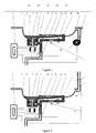
- FIG. 1 it is the first example of the invention, flushing lavatory with the circulated flushing and stool crushing structure A. It consists of toilet pan 3, crushing pump 5, flush liquid pump 28 and circuit control device 1.
- a crushing pump 5 is mounted at the outlet valley of the bottom of its back part.
- a crush pipe 8 is connected and its stool crushing nozzle is open and fixed at the front bottom of the pan 3, against the stool.
- the magnetic valve 12 controlling the open and close of the crush pipe 8 is set in it.
- the crush pipe 8 is connected with one side of the outlet valley of the crushing pump 5 and at the bottom of the crush pipe, a stool collecting pipe 22 is set.
- a magnetic valve 9 is mounted in the stool collecting pipe 22 to control the open and close of it.
- the other end of the pipe 22 is an open end, it can discharge the rejection out of the system.
- the crushing pump 5 is fixed in the outlet valley of the bottom of the toilet pan 3.
- the pump consists of motor 7, centrifugal flabellum 6, crushing tools 4 and other components.
- the motor 7 is fixed at the lateral portion of bottom of the toilet pan 3 and its output axis is set cross the inner cavity at the bottom of the pan 3.
- the centrifugal flabellum 6 and crushing tools 4 are mounted on the output axis. With the centrifugal effect, the centrifugal flabellum sucks the sewage in the toilet pan 3 into the crushing pump 5 and pump it out from the outlet.
- the crushing tool 4 fixed in the top of output axis will crush the solid flowing into the pump 5 at this time.
- the said flush liquid pump 28 and a flush pipe 20 are set at the front of the toilet pan 3.
- the outlet nozzle 16 of the open end of the flush pipe 20 is mounted at the front of toilet pan 3, the other end is connected with the flushing pump 28.
- One end of the flush pipe 20 is connected with the flush liquid or headwater, the other end-the outlet nozzle 16 is set at the front tip of the toilet pan 3, so that the flush liquid can reach all the positions the sewage will go.
- the liquid will flow into the toilet pan 3 with the action of flush liquid pump 28.
- the circuit control device 1 controls all the above electrical appliances.
- the magnetic valve 9 controlling the open and close of the stool collecting pipe 22 opens and the crushing pump 5 rotates.
- the sewage in the toilet pan 3 will be discharged out of the lavatory system through the crushing pump 5, the magnetic valve 9 and stool collecting pipe 22.
- the bottom of the toilet pan 3 there is small amount of gruel stool liquid without solid left.
- the stool crushing lavatory adding the above circulated flushing structure would decrease the flush liquid need to be used for each stool flushing from 6-12 liter to 0.5 liter and has no effect on the flushing result.
- the second embodiment of the invention the flushing lavatory with circulated flushing and stool crushing construction. It has the same structure with the first embodiment. The difference is the structure of the flush pipe is designed to another kind.
- the flush pipe 20, its flushing structure is setting a magnetic valve 38 to control its open and close.
- the magnetic valve 38 is controlled by instructions of the circuit control device 1.
- the flush pipe 20, one end of it is compressive flush liquid or headwater, and the other end is an outlet nozzle 16, which is set in front of the toilet pan 3 so that the nozzle 16 can make the flush liquid reach all the positions the sewage will go. Under the control instruction of the circuit control device 1, the magnetic valve 38 opens and the flush liquid will flow into the toilet pan 3 to flush with the action of the headwater pressure.
- the third embodiment of the invention has the same structure with the first and second embodiment.
- the difference is a urine collecting device B is set, then it becomes the invention, flushing lavatory with urine collecting device.
- the flushing lavatory can be installed on the ordinary stool crushing lavatory. It includes the toilet pan 3, the crushing pump 5 and the flush liquid pump 28, especially has a urine collecting device B.
- the urine collecting device B consists of urine collecting pipe 10, urine collecting box 26 and circuit control device.
- the toilet pan 3, the crushing pump 5 and the flush liquid pump 28 have the same structures with the first embodiment. It's no need to describe it anymore.
- the urine collecting pipe 10 is connected with valley of the discharge outlet at the back and bottom of the toilet pan 3. At the bottom of the urine collecting pipe 10, a stool collecting pipe 22 is connected, which has a magnetic valve 11 controlling the open and close of the pipe. Another end of urine collecting pipe 10 is extended and set in the urine collecting box 26. The urine collecting pipe 10 has a magnetic valve 11 controlling the open and close of the pipe.
- the urine collecting box 26 is an enclosed case and the urine collecting pipe 10 and flush liquid pump 28 are set in.
- the circuit control device 1 controls all the above electrical appliances.
- the said structures combine together and configure the flushing lavatory with urine collecting device.
- the circuit control device 1 controls the urine collecting magnetic valve 11 opens and the crushing pump 5 not working.
- the urine flows from the valley of the discharged outlet of the toilet pan 3 and through the crushing pump 5, urine collecting pipe 10 and urine collecting magnetic valve 11 into the urine collecting box 26, then urine collecting is finished. If there is stool in the toilet pan 3, after the urine collecting magnetic valve 11 opens, as the stool is uneasy to flow and the crushing pump doesn't work, it can prevent the stool flow into the urine collecting box 26 and the separation of liquid and solid is realized. Then the effective collection of urine in the stool is ensured.
- the flush liquid pump 28 starts and draws the urine out of the urine collecting box 26.
- the outlet nozzle 16 of the flush pipe 20 connected with the flush liquid or headwater at the front of the toilet pan 3 to discharge and flush.
- the flushed urine and the flush liquid flow into the toilet pan 3 with the action of flush liquid pump 28 rapidly.
- the mixed flush liquid will flush the pan rapidly and the pan is easy to be flushed clean.
- the stool collecting magnetic valve 9 opens and the sewage will be discharged out of the lavatory system through the stool collecting pipe 22.
- the urine collecting magnetic valve 11 opens under the control of the circuit control device 1. All the flush liquid will be conducted into the urine collecting box 26. With the urine collecting device, the lavatory may have the function of automatic flushing under the intelligent control.
- the fourth embodiment of the invention It has the same structure with the third embodiment (in Figure 4, the same structure with the Figure 3 is omitted). The difference is on the basis of the third embodiment, an automatic liquid medicine adding device C is further set and thus the invention-the flushing lavatory with the automatic liquid medicine adding device is configured.
- the automatic liquid medicine adding device C consists of medicine pot 17 and the circuit control device 1 Wherein:
- the medicine pot 17, refer to Figure 3,
- the medicine pot is in one side of the urine conducting pipe 10.
- the sterilized and environment protection liquid medicine 18, which can keep the urine without bad smell in a certain time, is stored in the medicine pot 17.
- a medicine conduct pipe 19 is connected at the bottom of the medicine pot. Another end of the pipe 19 is mounted on the urine collecting box 26 or connected with the urine conduct pipe 10 then to the urine collecting box 26.
- a medicine adding magnetic valve 15 controlling the open and close of the urine conduct pipe 10 is set between the urine conduct pipe 10 and the medicine pot 17, which is controlled by the circuit control device 1.
- the circuit control device 1 controls the above electrical appliances and the magnetic valve.
- the open and close of the urine conduct pipe is controlled by the medicine adding magnetic valve 15.
- the medicine adding magnetic valve 15 is controlled by the circuit control device 1. With the circuit control device 1 the medicine adding magnetic valve 15 can open once during every urine recovery. It makes the sterilized and environment protection liquid medicine 18 stored in the medicine pot 17 mix with the urine flowing from the outlet of the toilet pan 3 and becomes a mixed flush liquid. The flush liquid can eliminate the bad smell of the urine in a certain time and then the invention has the function of automatic environment protection liquid medicine and bad smell eliminating.
- the fifth embodiment of the invention has the same structure with the third embodiment.
- the difference is on the basis of the third embodiment, a double-pump flush device D is further set and the invention-the flushing lavatory with double-pump flush device is configured.
- the flushing lavatory also has the toilet pan 3, crushing pump 5, flush liquid pump 28, urine collecting pipe 10 and the urine collecting box 26.
- crushing pump 5, flush liquid pump 28, urine collecting pipe 10 and the urine collecting box 26 is same as the third embodiment, so it will not be described anymore.
- the double-pump flushing device D includes upper flush liquid pump 28, lower flush liquid pump 27, lower liquid conduct pipe 21, upper clean liquid conduct pipe 20 and circuit control device 1.
- the lower flush liquid pump 27 is fixed in the lower part of the upper flush liquid pump 28 and at the bottom of the urine collecting box 26.
- the lower and upper flush liquid pump 28 configure the double-pump flushing structure.
- the lower liquid conduct pipe 21, its upper end is lower liquid nozzle 40, which is fixed at the bottom of the toilet pan 3 and the other end is connected with the lower flush liquid pump 27.
- the upper clean liquid conduct pipe 20 its upper end is fixed with the clean liquid outlet nozzle 16 at the front tip of the toilet pan 3 and the other end is connected with the upper clean liquid pump 28.
- the circuit control device 1 controls the above electrical appliances.
- the above structures combine together and configure the invention-no headwater flushing lavatory with double-pump flushing device.
- the lower flush liquid pump 27 can draw out the urine sediment from the lower part of the urine collecting box 26.
- the urine sediment will reach the lower liquid nozzle 40 and spray at the back of the toilet pan 3 accumulating the stool and urine and flush it.
- the upper clean liquid pump 28 will draw out the urine clean liquid from the upper part of the urine collecting box 26.
- the urine clean liquid will reach the clean liquid nozzle 16 and also spray at the back of the toilet pan 3 accumulating the stool and urine and flush it repeatedly.
- the toilet pan 3 can be finally flushed clean without urine sediment left.
- the urine sediment liquid in the urine collecting box 26 is consumed during working and it will not accumulate more and more.
- the toilet pan 3 has two pumps used for pumping the urine flush liquid to flush, so the toilet pan can be flushed very clean without urine sediment left.
- the sixth embodiment of the invention the flushing lavatory with no headwater flushing system. It is the further innovated on the basis of the above embodiments. It combines the circulated flushing and stool crushing structure A (the first embodiment and the second embodiment), urine collecting device B (the third embodiment ), automatic liquid medicine adding device C ( the fourth embodiment ),double-pump flushing device D(the fifth embodiment) together and configure the invention, no headwater flushing lavatory.
- the no headwater flushing lavatory consists of the circuit control device 1, detection device 2, toilet pan 3, crushing pump 5, stool crushing pump 8, stool collecting magnetic valve 9, urine collecting pipe 10, urine collecting magnetic valve 11, stool crushing magnetic valve 12, medicine adding magnetic valve 15, upper clean liquid nozzle 16, medicine pot 17, medicine conduct pipe 19, upper clean liquid conduct pipe 20, lower liquid conduct pipe 21, stool collecting pipe 22, urine collecting box 26 and upper flush liquid pump 28.
- the above components have the same structures with the above embodiments and it will not be described anymore.
- a concentrated nozzle structure G, liquid level induct device F and detection device are further set.
- the concentrated nozzle structure G is the prescribed fifth embodiment.
- an one-way check valve 14 is connected at the upper tip end of the lower liquid conduct pipe 21 of the lower flush liquid pump 27 .
- the valve 14 is connected with the stool crush pipe 8 and they parallel connect and then connect together with the lower liquid nozzle 40 on the top.
- the effect of the one-way check valve 14 is to only permit the liquid drawn out from the urine collecting box 26 by the lower flush liquid pump 27 flush into the toilet from the nozzle 40 through the said valve, but not permit the liquid in the toilet pan 3 and stool crush pipe 8 to backflow into the urine collecting box 26.
- the liquid level induction system F consists of liquid level sensor 29, 30, which are set in the suitable position of the urine collecting box 26.
- the detection device 2 is located in the suitable position of the WC. It is used in the circuit control device 1 to detect if anyone is using the flushing lavatory.
- the detection device 2 can be the photodetection device mounted in the WC or the passive human body infrared detector and also can be the pressure sensor set under the floor of the WC or the position switch mounted on the door lock or cross-pin of the WC and other kinds of detection devices. As long as the state of the detection device can show if there is person in the WC. For example, when the user enters the WC, the human body will keep out or reflect the light sent by the photodetection device.
- the state of the photodetection device is changed and the infrared ray sent by the human body will make the state of the passive human body infrared detector changed.
- the state of the pressure sensor under the floor will be changed.
- people lock the door or the cross-pin it makes the open and close state of the position switch changed.
- the above working state of the detection device can illustrate if any person is using the flushing lavatory.
- the above structures combine together and configure the invention-flushing lavatory with no headwater flushing system.
- a sewage temporary storage device E is further set. They combine together and configure the discharge controllable no headwater flushing lavatory. It is the best embodiment with the combination of the above flushing devices.
- the sewage storage device consists of a stool collecting box 25 and the stool discharge pump 24.
- the stool collecting box 25 is an enclosed case and mounted at the outlet of the lower end of the stool collecting pipe 22 of the toilet pan 3
- the stool discharge pump 24 is set at the bottom of the stool collecting box 25 and a discharge pipe 23 is connected with it.
- the discharge pipe 23 extends upward out of the stool collecting box 25 and its outlet is connected with the external collection place.
- the bottom of the stool collecting pipe 22 in the toilet pan 3 is connected with stool collecting box 25.
- the timing starts according to the defecating and pissing beginning signal sent by the detection device 2.
- the urine collecting magnetic valve 11 opens and the urine will flow into the urine collecting box 26 through the crushing pump 5, urine collecting pipe 10.
- the separation of liquid and solid is realized.
- the circuit control device 1 orders the medicine adding magnetic valve 15 open and makes the environment protection liquid medicine 18 flow into the urine collecting pipe 10 through the medicine pot 17, liquid medicine conduct pipe 19 and mix with the collected urine.
- the mixed liquid will flow into the urine collecting box 26 and the change from the urine into the flush liquid is finished. If it is urine, when the user leaves the WC, the upper clean flush liquid pump 28 and the crushing pump 5 start. The flush liquid in the urine collecting box 26 will be pumped out by the upper clean flush liquid pump 28 and flow into the toilet pan 3 through the flush liquid pipe 20 and flush it. Then it will be sucked and pumped into the urine collecting pipe 10 with the urine by the crushing pump 5 and will flow back into the urine collecting box 26. If it is stool, the urine collecting magnetic valve 11 closes and the stool crushing magnetic valve 12 opens. Start the lower flush liquid pump 27 and let it last for a certain time.
- the lower flush liquid about 0.2 -0.3 liter with the urine sediment will spray into the toilet pan 3 through the lower liquid conduct pipe 21, one-way check valve 14 and nozzle 40.
- Start the crushing pump 5 and the flush liquid will have a circular flow in the path formed by the toilet pan 3, crushing pump 5, stool crushing pump 8, toilet pan 3.
- the stool crushing magnetic valve 12 closes and the stool collecting magnetic valve opens. It makes the gruel liquid flow into the stool collecting box 25 through the stool collecting pipe 22.
- the gruel stool liquid left in the toilet pan 3 will be flushed clean and pumped out by crushing pump 5. Finally, it will flow into the stool collecting box 25 through the stool collecting pipe 22. The gruel stool liquid left in the stool collecting box 25 will flow out of the flushing lavatory in suitable time (for example, in the fixed discharge time or someone is cleaning) and the controllable discharge is realized.
- FIG 7 is the statistical chart concerning service time of defecating or pissing used by the stool and urine automatic identification method and device. It shows the rule of consuming time of defecating and pissing for a person in an ordinary WC by the plane rectangular coordinates. It is the statistical chart drawn according to the sampling situation of the consuming time of defecating and pissing for several hundreds of people's continuous using in a real WC. There are two curves. Wherein: the real line shows the rule of the service time of the WC and the correspondent number of people. The vertical coordinate is the differential of the service time and service people. The abscissa represents the service time in the WC. The imaginary line shows the proportion of the number of people in the total counted people finishing use the WC before a specified time. Its vertical coordinate is the percentage and the abscissa is the service time in the WC.
- t0 is about between 1 minute to 1.5 minutes.
- a stool and urine identification device E for the automatic identification of stool and urine is set in the invention.
- the stool and urine automatic identification device E consists of circuit control device 1, detection device 2 and the program circuit set in the circuit control device 1 to identify the stool or urine.
- the detection device 2 is set as a sensor and connected with the input end of the circuit control device 1. It can transfer the detected signal to the circuit control device 1.
- the logical determination sketch map of the stool and urine identification device E of the circuit control device of the flushing lavatory not only can start the procedure of the flushing of the toilet pan 3 according to the user's leaving signal provided by the detection device 2, but also can start the timing based on the signal of the user entering the WC provided by the detection device 2. The timing procedure will end until the detection device 2 provides the user's leaving signal.
- the circuit control device 1 can identify the stool or urine based on the length of time made by the timing device. That is, when the using time is shorter than a specified eigenvalue t0, it is certain that it isn't the stool in the WC.
- the identification method can't separate all the stool or urine correctly, but it is certain that it can identify the number of people defecating.
- the reason why this method doesn't call "urine automatic identification method" is because the users leaving the WC in the time of t0, may piss or may do nothing.
- the control device of the no headwater flushing lavatory consists of human body detection device 2, stool box liquid level sensor 29, urine box liquid level sensor 30, control circuit 1, upper temperature sensor 36 (set in the suitable position of the WC), lower temperature sensor 37 (set in the suitable position of the bottom of the flushing lavatory in the WC), crushing pump motor 7, urine collecting magnetic valve 11, stool crushing magnetic valve 9, stool crushing magnetic valve 12, medicine adding magnetic valve 15, upper flush liquid pump 28, lower flush liquid pump 27, stool discharge pump 24, headlight in WC 31, occupancy indicating lamp 32, air exchange fan 33, frost-resistant heater 34, warmer 35.
- human body detection device 2 set in the suitable position of the WC
- lower temperature sensor 37 set in the suitable position of the bottom of the flushing lavatory in the WC
- the stool box liquid level sensor 29, urine box liquid level sensor 30, upper temperature sensor 36, lower temperature sensor 37 and human detection device 2 are all sensors.
- Crushing pump motor 7, urine collecting magnetic valve 11, stool collecting magnetic valve 9, stool crushing magnetic valve 12, medicine adding magnetic valve 15, upper flush liquid pump 28, lower flush liquid pump 27, stool discharge pump 24, headlight in WC 31, occupancy indicating lamp 32, air exchange fan 33, frost-resistant heater 34, warmer 35 are execution units.
- the said control circuit 1 receives the signal of liquid level, temperature and occupancy transferred from the above sensors and decides which execution unit works, the length of working and working times.
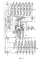
- the circuit control device 1 consists of the first part direct current power supply part 1, the second part sensor interface part 2, the third part control circuit part 3, the fourth part execution units driving circuit part 4.
- the sensors transfer the signals to the control circuit 3 through the sensor interface 2. After judged and calculated by the control circuit, the signals are transferred to the execution units driving circuit 4. Through the power magnification of the driving circuit 4, it will push every execution unit to work and operate.
- the first part is the direct current power supply circuit part 1, it consists of double voltage changer, bridge rectify circuit, three-terminal voltage regulator and its protective circuit diode and filter circuit.
- the alternating current inputs into the primary side of the changer and through the secondary side, outputs two lower voltage AC. And then, it inputs into the bridge rectify circuit and changes into a pulse direct current. Through the filter, it becomes a direct current. Through three-terminal voltage regulator and filter, it becomes a 5v DC and outputs two general ground +5v DC.
- the third part is the core control circuit part 3, it consists of chip microcomputer AT90S8535 and its attached circuit.
- the attached circuit includes crystal vibration providing operating frequency, the resistance and capacitance used for upper reset, the four or negation gate integrated circuit used for the gating of the liquid level sensor, warning buzzer, the interface used for the serial programming and on-line communication and the interface used for connecting the key board and LED indicator.
- the crystal vibration is connected with the foot 12, 13 of the input end of the crystal vibration of the chip microcomputer.
- the two ends of the crystal vibration are connected with two grounding capacitances.
- the upper reset resistance is connected with the foot 9 of the chip microcomputer and the foot 9 is connected with the grounding capacitance.
- the negative pole of the buzzer is connected with the foot 20 of the chip microcomputer and the positive pole is connected with the +5v voltage.
- the interface used for the serial programming and on-line communication is respectively connected with +5v and the foot 10, 5, 6, 7, 8, 9, 11 through the connection terminal of the foot 8.
- the foot 11 is grounding and the foot 10 is connected with +5v , a special line for the chip microcomputer.
- the interface of the keyboard and LED indicator is respectively connected with +5v, ground and the foot 3, 4, 17, 39, 38.
- the chip microcomputer AT90S8535 is produced by ATMEL Company in USA, it is a eight bit AVR chip microcomputer product. It has the functions of the inner n. watchdog, ten bit ADC converter, SPI synchronous serial communication, serial download program, pulling high, high resistance input model and so on.
- the circuit can transfer the voltage analog signal sent by the temperature sensor into the digital signal through the ten bit ADC converter connected at the foot 33, 34.
- the circuit uses the external clock/counter on the T1 of foot 2 to do frequency test on the pulse signal sent by the liquid level sensor.
- the circuit also use the inner pulling high function on the foot 30,37 to identify the human body detection switching signal and send the instruction to the correspondent execution units driving circuit through the logical decision.
- the chip microcomputer occupies the +5v voltage output by the DC power circuit on foot 10 individually and another +5v voltage output by the DC power circuit provides the DC voltage of the whole circuit except the chip microcomputer.
- the above DC voltage is connected on the external interrupt input interface INTO on the foot 16 of the chip microcomputer.
- the interrupt input interface is set as trailing edge trigger.
- the chip microcomputer will detect the power-failure through the external interrupt input interface and protect the state field before the power-failure, so that the field can be restored and the work can be done continuously when powers on again.
- the design is against the effect of the short time power-failure or the voltage disturbance on the program decision.
- the second part is the interface circuit of the sensor 2.
- the interface circuit of human body detection device consists of connection terminal and capacitance connected on the foot 36, 37.
- the above two feet are set as input and its states are pulling high. They are connected with ground and pulling low by the sensor to judge if there is person or not.
- the liquid level sensor its connection terminal of the interface is connected with the four or negation gate integrated circuit.
- the four or negation gate integrated circuit can gate the square wave input by the two liquid level sensors through the connection as shown in the figure.
- the control end is gated to connect with the foot 1 of the chip microcomputer, the square wave inputs into the foot 2 of the chip microcomputer.
- the foot 1 is set as output and the foot 2 is set as the high-resistance state or pulling high state of the input.
- the high-low of the liquid level is determined in accordance with the frequency of the square wave sent by the liquid level sensor.
- the temperature sensor its interface circuit consists of connection and capacitance connected on the foot 33, 34 of the chip microcomputer.
- the two feet are set as input and present as the high-resistance state.
- the high-low of the temperature is determined by the voltage value sent by the temperature sensor.
- the fourth part is the execution units driving circuit 4. It consists of thirteen complete same driving elements. Every driving element includes optical coupling driving circuit, supper power crystal brake tube, protective high pressure proof capacitance and piezoresistance, wherein:
- the optical coupling driving circuit its input end is connected with the signal output end of the chip microcomputer and +5v.
- the output end of the optical coupling is connected with the input end of the supper power crystal brake tube.
- the supper power crystal brake tube its output end is connected with the parallel connected high pressure capacitance, piezoresistance and execution units.
- the chip microcomputer outputs the low electric potential
- the light-emitting diode in the optical couple will brighten and the light-sensitive and two-way crystal brake tube in its inner output end conducts and drives the high power two-way crystal brake tube conduct so as to drive the correspondent execution unit.
- the zero passage driving circuit is set in the light-sensitive and two-way crystal brake tube of the optical couple driving circuit. It will conduct at the moment of receiving the optical signal and meeting the zero AC voltage. Thus, it can avoid the appearance of power waveform disorder caused by the sudden loading on the execution unit, and it also can avoid the damage of circuit and the loss of the execution unit and the program of the chip microcomputer.
- the high pressure capacitance has the function of absorbing the high-frequency clutter.
- the piezoresistance conducts at the time of overvoltage and has the protective function on the circuit and execution unit.
- the output end of the above thirteen paths execution units driving elements is connected with the thirteen output base pins 14, 15, 18, 19, 21, 22, 23, 24, 25, 26, 27, 28, 29 of the chip microcomputer and the input end is connected respectively with crushing pump motor 7, urine collecting magnetic valve 11, stool collecting magnetic valve 9, stool crushing magnetic valve 12, medicine adding magnetic valve 15, upper flush liquid pump 28, lower flush liquid pump 27, stool discharge pump 24, headlight in WC 31, occupancy indicating lamp 32, air exchange fan 33, frost-resistant heater 34 and warmer 35.
- the execution unit is controlled by the correspondent base pin of the chip microcomputer.
- the flushing lavatory with the particular structure has the above advantages and practical value. It has innovation on the space structure conformation. Comparing with the prior flushing lavatory, many new functions have been promoted and its structure is simple. The invention has big technical progress and the excellent effect of easy using. It is a new design with novelty, advancement and practicability and has widely utilizing value in the industry.
Landscapes
- Health & Medical Sciences (AREA)
- Public Health (AREA)
- Engineering & Computer Science (AREA)
- Life Sciences & Earth Sciences (AREA)
- Hydrology & Water Resources (AREA)
- Water Supply & Treatment (AREA)
- Aviation & Aerospace Engineering (AREA)
- Epidemiology (AREA)
- Sanitary Device For Flush Toilet (AREA)
- Bidet-Like Cleaning Device And Other Flush Toilet Accessories (AREA)
Abstract
Description
Refer to figure 4, the fourth embodiment of the invention. It has the same structure with the third embodiment (in Figure 4, the same structure with the Figure 3 is omitted). The difference is on the basis of the third embodiment, an automatic liquid medicine adding device C is further set and thus the invention-the flushing lavatory with the automatic liquid medicine adding device is configured. The automatic liquid medicine adding device C consists of
Claims (16)
- A flushing lavatory, it includes the toilet pan, crushing pump which is set at the outlet valley of the bottom of the toilet pan; wherein it contains the innovated toilet pan and circuit control device, Wherein:the innovated toilet pan, in the bottom near the front, a crush pipe is connected; the magnetic valve controlling the open and close of the crush pipe is set in; the crush pipe is connected with one side of the outlet valley of the crushing pump and at the bottom of the crush pipe, a stool collecting pipe is set; a magnetic valve is mounted in the stool collecting pipe to control the open and close of it; the other end of the pipe is an open end, it can discharge the rejection out of the system;the circuit control device can control all the above electric appliances;the above structures combine together and configure the invention of the flushing lavatory with the recycled flushing and stool crushing structure; when flush the stool, under the control of the circuit control device, the flush liquid will form a positive circulation in the ring-shaped path made by toilet pan, crushing pump, crushing pump magnetic valve, rush pipe and toilet pan; the stool in the pan is flushed into the crushing pump to crush and it will mix with the flush liquid and become a gruel liquid; the circuit control device will open the magnetic valve controlling the open and close of the stool collecting pipe; then the crushing pump works and the sewage in the toilet pan will go through the crushing pump, magnetic valve, stool collecting pipe and will be discharged out of the system; through the action of recycled flushing structure, people can save a large amount of water and the water saving effect is rather considerable.
- The prescribed flushing lavatory of claim 1, wherein at the front of the said toilet, a flush pipe is connected; the pipe has a magnetic valve to control open and close of the pipe; the circuit control device controls the magnetic valve; one end of the flush pipe is connected compressive flush liquid or headwater, and the other end is an outlet nozzle, which is set in front of the toilet pan so that the nozzle can make the flush liquid reach all the positions the sewage will go; under the control instruction of the circuit control device, the magnetic valve opens and the flush liquid will flow into the toilet pan to flush with the action of the headwater pressure.
- The flushing lavatory of claim 1, wherein at the front of the said toilet, a flush liquid pump is connected and a flush pipe is set; the outlet nozzle of the open end of the flush pipe is mounted at the front of toilet, the other end is connected with the flushing pump; one end of the flush pipe is connected with the flush liquid or headwater, the other end-the outlet nozzle is set at the front tip of the toilet, so that the flush liquid can reach all the positions the sewage will go; the liquid will flow into the toilet pan with the action of flush liquid pump.
- The flushing lavatory of claim 3, wherein a urine collecting device is included; the device consists of urine collecting pipe, urine collecting box and circuit control device; wherein:the urine collecting pipe is connected with valley of the discharge outlet at the back and bottom of the toilet; at the bottom of the urine collecting pipe, a stool collecting pipe is connected, which has a magnetic valve controlling the open and close of the pipe; another end of urine collecting pipe is extended and set in the urine collecting box; the urine collecting pipe has a magnetic valve controlling the open and close of the pipe;the box is an enclosed case and the urine collecting pipe and flush liquid pump are set in;the said structures combine together and configure the no headwater flushing system-recycled and stool crush flushing lavatory with urine collecting device; the circuit control device controls the open and close of the urine collecting magnetic valve and it also can control the crushing pump not working; the urine flows from the valley of the discharged outlet of the toilet and goes through the crushing pump, urine collecting pipe and urine collecting magnetic valve into the urine collecting box, then urine collecting is finished; when the crushing pump doesn't work, it can prevent the stool flowing into the urine collecting box and the separation of liquid and solid is realized; with the urine collecting device, the lavatory may have the function of automatic flushing under the intelligent control.
- The flushing lavatory of claim 4, wherein an automatic liquid medicine adding device is set; the liquid medicine adding device consists of medicine pot and the circuit control device, wherein:the medicine pot is in the upper side of the urine collecting box; the liquid medicine is stored in the medicine pot; a medicine conduct pipe is connected at the bottom of the medicine pot; another end of the pipe is mounted on the urine collecting box or connected with the urine conduct pipe then to the urine collecting box; a circuit control device is set in the urine conduct pipe to control the magnetic valve; the magnetic valve can control the open and close of the medicine conduct pipe;the circuit control device controls the said electrical appliances and magnetic valve;the above structures combine together and configure the invention of no headwater flushing lavatory with automatic liquid medicine adding device; through the circuit control device the medicine adding magnetic valve may open during each urine collection; the medicine in the medicine pot will mix with the urine flowing from the outlet of the toilet pan and become a mixed flush liquid; it can eliminate the bad smell of the urine; the invention has the function of automatic environment protection liquid medicine adding and bad smell elimination.
- The flushing lavatory of claim 4, wherein a double-pump flushing device is set; the double-pump flushing device includes upper flush liquid pump, lower flush liquid pump, lower liquid conduct pipe, upper clean liquid conduct pipe and circuit control device, wherein:the lower flush liquid pump is fixed in the lower part of the upper flush liquid pump and at the bottom of the urine collecting box; the lower and upper flush liquid pump configure the double-pump flushing structure;the lower liquid conduct pipe, its upper end is lower liquid nozzle, which is fixed at the bottom of the toilet and the other end is connected with the lower flush liquid pump;the upper clean liquid conduct pipe, its upper end is fixed with the clean liquid outlet nozzle at the front tip of the toilet and the other end is connected with the upper clean liquid pump;the said circuit control device controls the above electrical appliances;the above structures combine together and configure the invention-no headwater flushing lavatory with double-pump flushing device; with the control of circuit control device, the lower flush liquid pump can draw out the urine sediment from the lower part of the urine collecting box and spray at the back of the toilet accumulating the stool and urine and flush it through the lower liquid nozzle; and then the upper clean liquid pump will draw out the urine clean liquid from the upper part of the urine collecting box; through the upper clean liquid nozzle, it also can spray at the back of the toilet accumulating the stool and urine and flush the toilet repeatedly; the invention has the function of flushing the toilet extremely clean and no urine sediment left.
- The flushing lavatory of claim 6, wherein a concentrated nozzle structure is set; at the upper tip end of the lower liquid conduct pipe of the lower flush liquid pump, a one-way check valve is connected; the valve is parallel connected with the stool crush pipe and then connected together with the lower liquid nozzle on the top; the above structures combine with each other and configure the invention-no headwater flushing lavatory with concentrated nozzle structure and double-pump flushing device.
- The flushing lavatory of claim 7, wherein a human body detection device is set; the device is located in the suitable position of the WC; it is used in the circuit control device to detect if anyone is using the flushing lavatory; the detection device can be the photodetection device mounted in the WC or the passive human body infrared detector and also can be the pressure sensor set under the floor of the WC or the position switch mounted on the door lock or cross-pin of WC and other kinds of detection devices; the above structures combine together and configure the invention-flushing lavatory with human body detection device; the working state of the above detection devices can detect if anyone is using the flushing lavatory and is controlled by the circuit control device.
- The flushing lavatory of claim 8, wherein a liquid level induction system is set; the device consists of liquid level sensor, which is set in the suitable position of the urine collecting box; the above structures combine together and configure the invention-no headwater flushing lavatory with the liquid level induction system.
- The flushing lavatory of claim 9, wherein the prescribed human body detection device and the circuit control device are the automatic identification method in accordance with the stool and urine; the method is: at first, record the time people using the lavatory; the timing begins from the detection device provides the user entry signal; the timing ends at the time of the detection device provides the user leaving signal; the circuit control device will identify the stool or urine according to the length of time made by the timing device; if the using time is shorter than an eigenvalue t0, it is not the stool; if a specific person spends long time when pissing, the device still can identify that it is not the stool correctly.
- The flushing lavatory of claim 10, wherein a stool and urine identification device which can identify the stool or urine automatically; the device consists of circuit control device, detection device and the program circuit set in the circuit control device to identify the stool or urine; the detection device is set as a sensor and connected with the input end of the circuit control device; it can transfer the detected signal to the circuit control device.
- The flushing lavatory of claim 11, wherein a sewage temporary storage device is further set; the said device consists of a stool collecting box, which is an enclosed case and mounted at the outlet of the lower end of the stool collecting pipe of the toilet; the above structures combine together and configure the invention-discharge controllable flushing lavatory.
- The flushing lavatory of claim 12, wherein the said stool collecting box has a stool discharge pump, which is set at the bottom of the stool collecting box; a discharge pipe is connected with the pump and extended upward out of the stool collecting box; the outlet of the pipe is connected with the external collection entrance;
the above structures combine together and configure the invention-electric control discharge flushing lavatory; the liquid stool in the toilet pan will be pumped out by the crushing pump and flow into the stool collecting box; when it is necessary, the stool liquid will be pumped out by the stool discharge pump and the electric control discharge is realized. - The flushing lavatory of claim 13, wherein the said circuit control device consists of human body detection device, stool box liquid level sensor, urine box liquid level sensor, control circuit, upper temperature sensor, lower temperature sensor, crushing pump motor, urine collecting magnetic valve, stool crushing magnetic valve, medicine adding magnetic valve, upper flush liquid pump, lower flush liquid pump, stool discharge pump, headlight in WC, occupancy indicating lamp, air exchange fan, frost-resistant heater, warmer; Wherein:the stool box liquid level sensor, urine box liquid level sensor, upper temperature sensor, lower temperature sensor and human detection device are all sensors;the crushing pump motor, urine collecting magnetic valve, stool collecting magnetic valve, stool crushing magnetic valve, medicine adding magnetic valve, upper flush liquid pump, lower flush liquid pump, stool discharge pump, headlight in WC, occupancy indicating lamp, air exchange fan, frost-resistant heater, warmer are execution units;the said control circuit receives the signal of liquid level, temperature and occupancy transferred from the above sensors and decides which execution unit works, the length of working and working times.
- The flushing lavatory of any claim from claim 1 to claim 14, wherein the said circuit control device consists of the first part direct current power supply part 1, the second part sensor interface part 2, the third part control circuit part 3, the fourth part execution units driving circuit part 4; the sensors transfer the signals to the control circuit 3 through the sensor interface 2; after judged and calculated by the control circuit, the signals are transferred to the execution units driving circuit 4; through the power magnification of the driving circuit 4, it will drive the execution units to operate and work.
- The flushing lavatory of claim 15, wherein the said circuit control device, wherein: the direct current power supply circuit part 1 consists of double voltage changer, bridge rectify circuit, three-terminal voltage regulator and its protective circuit diode and filter circuit; the alternating current inputs into the primary side of the changer and through the secondary side, outputs two lower voltage AC; it inputs into the bridge rectify circuit and changes into a pulse direct current; through the filter, it becomes a direct current; through three-terminal voltage regulator and filter, it becomes a 5v DC and outputs two general ground +5v DC;
the core control circuit part 3 consists of chip microcomputer and its attached circuit; the attached circuit includes crystal vibration providing operating frequency, the resistance and capacitance used for upper reset;
the chip microcomputer can change the voltage analog signal sent by the temperature sensor into the digital signal through the AD converter; it also can make the frequency test on the pulse signal transferred by the liquid level sensor through the external clock/counter and identify the human detection switch signal through the inner set pulling high input function; it can send the instructions to the correspondent execution units driving circuit by logical judgment;
the sensor interface circuit 2, the human body detection device interface circuit includes connection terminal and capacitance and is connected to the chip microcomputer to judge having person or not;
the liquid level sensor, its connection terminal of the interface is connected with the four or negation gate integrated circuit and then to the chip microcomputer; it judges the high-low of the liquid level by the frequency of the square wave signal transferred from the liquid level sensor;
the temperature sensor, its interface circuit includes the connection terminal and capacitance and is connected with the chip microcomputer; it judges the high-low of the temperature by the frequency of the square wave signal transferred from the liquid level sensor;
the execution units driving circuit 4, it consists of thirteen complete same driving elements; every driving element includes optical coupling driving circuit, supper power crystal brake tube, protective high pressure proof capacitance and piezoresistance, wherein,
the optical coupling driving circuit, its input end is connected with the signal output end of the chip microcomputer and +5v; the output end of the optical coupling is connected with the input end of the supper power crystal brake tube;
the supper power crystal brake tube, its output end is connected with the parallel connected high pressure capacitance, piezoresistance and execution units;
the output end of the above thirteen paths execution units driving elements is connected with the thirteen output base pins of the chip microcomputer and the input end is connected respectively with crushing pump motor, urine collecting magnetic valve, stool collecting magnetic valve, stool crushing magnetic valve, medicine adding magnetic valve, upper flush liquid pump, lower flush liquid pump, stool discharge pump, headlight in WC, occupancy indicating lamp, air exchange fan, frost-resistant heater and warmer; the execution unit is controlled by the correspondent base pin of the chip microcomputer.
Applications Claiming Priority (3)
| Application Number | Priority Date | Filing Date | Title |
|---|---|---|---|
| CNB011090979A CN1141469C (en) | 2001-02-28 | 2001-02-28 | Cyclic flusher for breaking excrement in toilet and flushing system without water source for toilet |
| CN01109097 | 2001-02-28 | ||
| PCT/CN2002/000130 WO2002068764A1 (en) | 2001-02-28 | 2002-02-28 | A flushing toilet |
Publications (2)
| Publication Number | Publication Date |
|---|---|
| EP1384831A1 true EP1384831A1 (en) | 2004-01-28 |
| EP1384831A4 EP1384831A4 (en) | 2005-11-02 |
Family
ID=4657722
Family Applications (1)
| Application Number | Title | Priority Date | Filing Date |
|---|---|---|---|
| EP02703481A Withdrawn EP1384831A4 (en) | 2001-02-28 | 2002-02-28 | A flushing toilet |
Country Status (12)
| Country | Link |
|---|---|
| US (1) | US20040143893A1 (en) |
| EP (1) | EP1384831A4 (en) |
| JP (1) | JP3935076B2 (en) |
| KR (1) | KR100640303B1 (en) |
| CN (2) | CN1141469C (en) |
| AU (1) | AU2002237188B2 (en) |
| CA (1) | CA2439131A1 (en) |
| MX (1) | MXPA03007438A (en) |
| NZ (1) | NZ527757A (en) |
| RU (1) | RU2305155C2 (en) |
| WO (1) | WO2002068764A1 (en) |
| ZA (1) | ZA200306538B (en) |
Cited By (3)
| Publication number | Priority date | Publication date | Assignee | Title |
|---|---|---|---|---|
| WO2008025109A1 (en) * | 2006-08-29 | 2008-03-06 | Martins Jose Santos | Volume super - reduced toilet flushing system, to be used in any kind of hydro-sanitary installation and for all models in sanitary appliances |
| EP1961875A4 (en) * | 2005-12-14 | 2015-02-25 | Hao Wu | Toilet |
| US10729290B2 (en) | 2016-03-01 | 2020-08-04 | Cranfield University | Toilet and operation thereof |
Families Citing this family (50)
| Publication number | Priority date | Publication date | Assignee | Title |
|---|---|---|---|---|
| US6035704A (en) * | 1998-06-12 | 2000-03-14 | Newman; Michael R. | Apparatus for the enhancement of water quality in a subterranean pressurized water distribution system |
| US7434781B2 (en) * | 2003-05-31 | 2008-10-14 | Taylor Thomas M | Remotely actuated quick connect/disconnect coupling |
| US7276159B2 (en) * | 2003-05-31 | 2007-10-02 | Taylor Thomas M | Water flushing system providing treated discharge |
| RU2397294C2 (en) * | 2005-12-14 | 2010-08-20 | Хао Ву | Waterless toilet with flushing device and flushing pump |
| US8307470B2 (en) * | 2006-10-24 | 2012-11-13 | Oved Abadi | Toilet flushing without using a toilet tank |
| KR100830205B1 (en) * | 2007-06-07 | 2008-05-16 | 창원환경산업 주식회사 | Flush toilets with low specific gravity |
| CN201416204Y (en) * | 2009-05-19 | 2010-03-03 | 吴昊 | Excrement disc device and a toilet flushing device without water having same |
| KR100968579B1 (en) * | 2009-09-22 | 2010-07-08 | 창원환경산업 주식회사 | Toilet bowl using low specific gravity |
| KR101200281B1 (en) | 2010-02-08 | 2012-11-09 | 이길산 | toilet |
| DE202010014643U1 (en) * | 2010-10-26 | 2012-01-26 | Evac Gmbh | Valve arrangement for the removal of a liquid medium |
| CN102009623A (en) * | 2010-11-24 | 2011-04-13 | 常联营 | Embedded no-water self-flushing vehicle-mounted closestool |
| CN102180573B (en) * | 2011-03-22 | 2013-04-24 | 黄少彬 | Automatic clearing device for solar energy filtration toilet |
| US9151023B2 (en) | 2011-05-27 | 2015-10-06 | Mueller International, Llc | Systems and methods for controlling flushing apparatus and related interfaces |
| JP5794960B2 (en) * | 2012-08-29 | 2015-10-14 | 株式会社Lixil | Toilet facilities |
| US9603496B1 (en) * | 2013-03-15 | 2017-03-28 | David C. Hartman | Toilet seat assembly |
| CN103860095B (en) * | 2014-03-26 | 2016-07-27 | 西安建筑科技大学 | Fecaluria separate type water-saving ecological lavatory |
| CN104179230A (en) * | 2014-07-31 | 2014-12-03 | 成都市飞龙水处理技术研究所 | Public toilet with water-free, water-saving and clay fertilizer production device and manufacturing method thereof |
| CN105193567B (en) * | 2015-08-12 | 2021-04-30 | 宁波同创电器有限公司 | Excrement treatment device for nursing bed |
| CN105064479A (en) * | 2015-08-12 | 2015-11-18 | 宁波同创电器有限公司 | Purification system for sanitary equipment |
| CN105113599A (en) * | 2015-08-12 | 2015-12-02 | 宁波同创电器有限公司 | Excrement treatment device and method |
| CN105064477A (en) * | 2015-09-01 | 2015-11-18 | 吴文中 | Water-saving environment-friendly excrement and urine separation and collection closestool |
| CN105541066B (en) * | 2016-01-26 | 2017-12-19 | 牡丹江等离子体物理应用科技有限公司 | Full-automatic bedpan processor |
| CN108204025A (en) * | 2017-11-15 | 2018-06-26 | 广州雅隆自动化设备有限公司 | A kind of urine bowl device of Novel urine recycling |
| CN108420351A (en) * | 2018-03-07 | 2018-08-21 | 苏州顶裕生物科技有限公司 | A kind of public lavatory of automatic degradation treatment |
| US10564653B2 (en) | 2018-04-13 | 2020-02-18 | Mueller International, Llc | Flushing verification and management system |
| DE102019103544A1 (en) * | 2019-02-13 | 2020-08-13 | Bayerische Motoren Werke Aktiengesellschaft | Method for controlling a metering valve, tank ventilation system and motor vehicle |
| CN109965762B (en) * | 2019-04-28 | 2024-05-31 | 中国航天空气动力技术研究院 | A pneumatic thermal environmentally friendly toilet, installation method and application thereof |
| CN110215149B (en) * | 2019-05-24 | 2024-08-06 | 中国航天空气动力技术研究院 | A kind of odor-free pneumatic hot toilet, installation method and application thereof |
| CN112064743A (en) * | 2019-06-11 | 2020-12-11 | 北京摩室科技有限公司 | A water-saving toilet and its operation method |
| CN110261629A (en) * | 2019-07-26 | 2019-09-20 | 重庆德方信息技术有限公司 | Dropping liquid cleaning mechanism for health test apparatus |
| CN110346182A (en) * | 2019-07-26 | 2019-10-18 | 重庆德方信息技术有限公司 | Stool sample acquisitions control system |
| CN110376022B (en) * | 2019-07-26 | 2022-04-12 | 重庆德方信息技术有限公司 | Sampling and sample-sending pipeline for intelligent closestool |
| CN110792142B (en) * | 2019-12-03 | 2024-07-16 | 长沙理工大学 | Urine water diverter and urine separating and collecting device comprising same |
| CN110840313B (en) * | 2019-12-12 | 2025-05-30 | 云南截尿资源再生利用有限公司 | A water-free flushable device for separating and collecting feces and urine |
| US11564666B2 (en) * | 2020-01-16 | 2023-01-31 | Medic, Inc. | Toilet with consumable material separating feces from bowl |
| CN111956114B (en) * | 2020-06-05 | 2022-02-22 | 中国水利水电科学研究院 | Excrement and urine processing apparatus and lavatory |
| CN112607869B (en) * | 2020-12-10 | 2023-01-03 | 上海林海生态技术股份有限公司 | Plant filter tank and method suitable for ecological toilet flushing water treatment |
| CN112870053B (en) * | 2021-01-19 | 2023-01-17 | 付军志 | Cleaning basin for gynecological and obstetrical nursing and working method thereof |
| CN112814110B (en) * | 2021-02-22 | 2025-02-28 | 九牧厨卫股份有限公司 | Drainage device, toilet and flushing method of toilet |
| CN112832339A (en) * | 2021-02-26 | 2021-05-25 | 浙江德丽洁生物科技有限责任公司 | Urine sterilization and disinfection toilet |
| CN113685982A (en) * | 2021-07-16 | 2021-11-23 | 青岛海尔空调器有限总公司 | Air conditioner control method, control device, and air conditioner |
| CN114568989B (en) * | 2022-03-31 | 2023-02-17 | 四川逸间科技有限责任公司 | Self-cleaning excrement and urine separation system with safety shielding function |
| CN115024653A (en) * | 2022-07-12 | 2022-09-09 | 台州小嗨环境科技有限公司 | Biodegradable water-free public toilet |
| CN115678853A (en) * | 2022-11-14 | 2023-02-03 | 成都复兴医院有限公司 | Urine circulating tumor cell collection method and system |
| CN116290259A (en) * | 2023-04-11 | 2023-06-23 | 王景富 | An environmentally friendly toilet |
| CN117166588B (en) * | 2023-07-28 | 2026-03-03 | 厦门市光弘电子有限公司 | Magnetic induction foot kick |
| CN117188584B (en) * | 2023-09-13 | 2025-11-18 | 西安超视距智能科技有限公司 | An integrated squat toilet with negative pressure suction and pulverizing/lifting functions |
| CN119122062A (en) * | 2024-04-29 | 2024-12-13 | 吴昊 | A non-water flush toilet system and working method thereof |
| CN119014734A (en) * | 2024-09-04 | 2024-11-26 | 吴昊 | A water-free flushable toilet with feces and urine separation and its working method |
| CN119631909B (en) * | 2025-02-18 | 2025-06-27 | 山东纽芬特农机制造有限公司 | A observe and feed case for poultry animal doctor |
Family Cites Families (10)
| Publication number | Priority date | Publication date | Assignee | Title |
|---|---|---|---|---|
| US3520003A (en) * | 1968-01-05 | 1970-07-14 | Charles J Shaw | Toilet unit |
| US3713177A (en) * | 1971-08-30 | 1973-01-30 | Nantron Corp | Marine toilet |
| US4131959A (en) * | 1977-06-03 | 1979-01-02 | International Water Saving Systems, Inc. | Non-polluting toilet system |
| US4347142A (en) * | 1979-05-11 | 1982-08-31 | International Water Saving Systems, Inc. | Effluent treatment in a non-polluting toilet system |
| CN2101960U (en) | 1991-09-12 | 1992-04-15 | 刘永生 | Over-pressure automatic protector for domestic electric appliance |
| US5400443A (en) * | 1993-10-01 | 1995-03-28 | Marino; John | Waste processing toilet |
| CN1132295A (en) * | 1995-03-24 | 1996-10-02 | 黄金富 | Public conveniences male urinal with urine collecting appts. |
| US5987658A (en) * | 1998-09-30 | 1999-11-23 | Wilcox Crittenden, Inc. | Single motor, dual clutch marine vessel toilet |
| CN2399461Y (en) * | 1999-12-21 | 2000-10-04 | 吴昊 | Circulating flushing, pollusion-less intermittent discharging toilet system |
| US6357056B2 (en) * | 2000-04-18 | 2002-03-19 | Control Fluidics, Inc. | Water saving toilet system |
-
2001
- 2001-02-28 CN CNB011090979A patent/CN1141469C/en not_active Expired - Fee Related
-
2002
- 2002-02-28 CN CNB028051386A patent/CN1238612C/en not_active Expired - Lifetime
- 2002-02-28 JP JP2002567654A patent/JP3935076B2/en not_active Expired - Fee Related
- 2002-02-28 EP EP02703481A patent/EP1384831A4/en not_active Withdrawn
- 2002-02-28 NZ NZ527757A patent/NZ527757A/en not_active IP Right Cessation
- 2002-02-28 KR KR1020037010952A patent/KR100640303B1/en not_active Expired - Fee Related
- 2002-02-28 MX MXPA03007438A patent/MXPA03007438A/en active IP Right Grant
- 2002-02-28 AU AU2002237188A patent/AU2002237188B2/en not_active Ceased
- 2002-02-28 RU RU2003126574/03A patent/RU2305155C2/en not_active IP Right Cessation
- 2002-02-28 CA CA002439131A patent/CA2439131A1/en not_active Abandoned
- 2002-02-28 WO PCT/CN2002/000130 patent/WO2002068764A1/en not_active Ceased
-
2003
- 2003-08-21 ZA ZA200306538A patent/ZA200306538B/en unknown
- 2003-08-28 US US10/650,269 patent/US20040143893A1/en not_active Abandoned
Cited By (3)
| Publication number | Priority date | Publication date | Assignee | Title |
|---|---|---|---|---|
| EP1961875A4 (en) * | 2005-12-14 | 2015-02-25 | Hao Wu | Toilet |
| WO2008025109A1 (en) * | 2006-08-29 | 2008-03-06 | Martins Jose Santos | Volume super - reduced toilet flushing system, to be used in any kind of hydro-sanitary installation and for all models in sanitary appliances |
| US10729290B2 (en) | 2016-03-01 | 2020-08-04 | Cranfield University | Toilet and operation thereof |
Also Published As
| Publication number | Publication date |
|---|---|
| RU2003126574A (en) | 2005-03-10 |
| CN1373266A (en) | 2002-10-09 |
| WO2002068764A1 (en) | 2002-09-06 |
| JP2004521202A (en) | 2004-07-15 |
| CA2439131A1 (en) | 2002-09-06 |
| EP1384831A4 (en) | 2005-11-02 |
| KR20030078929A (en) | 2003-10-08 |
| ZA200306538B (en) | 2004-09-03 |
| NZ527757A (en) | 2006-10-27 |
| RU2305155C2 (en) | 2007-08-27 |
| CN1492960A (en) | 2004-04-28 |
| CN1141469C (en) | 2004-03-10 |
| US20040143893A1 (en) | 2004-07-29 |
| MXPA03007438A (en) | 2004-10-15 |
| CN1238612C (en) | 2006-01-25 |
| KR100640303B1 (en) | 2006-10-30 |
| AU2002237188B2 (en) | 2006-03-16 |
| JP3935076B2 (en) | 2007-06-20 |
Similar Documents
| Publication | Publication Date | Title |
|---|---|---|
| EP1384831A1 (en) | A flushing toilet | |
| JP2004521202A5 (en) | ||
| CN201347565Y (en) | Building automatic-circulation water-saving system | |
| CN205892901U (en) | Can store non -potable water's among reverse osmosis water purification machine device | |
| CN101230592A (en) | Auto-induction urinating bucket | |
| EP1961875B1 (en) | Toilet | |
| CN1966874A (en) | Classification-utilization water-saving method for domestic water and device for automatically controlling classification-utilization | |
| CN210767080U (en) | Water-saving toilet | |
| CN109868863A (en) | Water rinses toilet device in a kind of utilization | |
| CN209975611U (en) | Device for flushing toilet by using reclaimed water | |
| CN2550425Y (en) | Flushing toilet | |
| CN105654636A (en) | Multifunctional human body infrared induction device for toilet | |
| CN208777387U (en) | A domestic wastewater treatment and recycling system | |
| CN205428077U (en) | Multi -functional human body IR induction device is used in lavatory | |
| CN104120772A (en) | Intelligent directly-drained type closestool | |
| CN2518914Y (en) | Device for recovering domestic sewage from floor drain | |
| CN108204018A (en) | A kind of toilet flushing device of intelligent recognition stool and urine | |
| CN201059002Y (en) | Public Building Wastewater Reuse System | |
| CN112064743A (en) | A water-saving toilet and its operation method | |
| RU2397294C2 (en) | Waterless toilet with flushing device and flushing pump | |
| CN209941822U (en) | Squatting pan capable of preventing excrement from being retained | |
| CN210507681U (en) | One-piece sanitary ware | |
| TWM647780U (en) | Recycling system for sewage | |
| NZ569165A (en) | Toilet with crush pump | |
| CN206767664U (en) | A kind of matching used Sewage treatment bucket of water purifier |
Legal Events
| Date | Code | Title | Description |
|---|---|---|---|
| PUAI | Public reference made under article 153(3) epc to a published international application that has entered the european phase |
Free format text: ORIGINAL CODE: 0009012 |
|
| 17P | Request for examination filed |
Effective date: 20030926 |
|
| AK | Designated contracting states |
Kind code of ref document: A1 Designated state(s): AT BE CH CY DE DK ES FI FR GB GR IE IT LI LU MC NL PT SE TR |
|
| AX | Request for extension of the european patent |
Extension state: AL LT LV MK RO SI |
|
| A4 | Supplementary search report drawn up and despatched |
Effective date: 20050916 |
|
| RIC1 | Information provided on ipc code assigned before grant |
Ipc: 7E 03D 9/10 A |
|
| 17Q | First examination report despatched |
Effective date: 20080131 |
|
| STAA | Information on the status of an ep patent application or granted ep patent |
Free format text: STATUS: THE APPLICATION IS DEEMED TO BE WITHDRAWN |
|
| 18D | Application deemed to be withdrawn |
Effective date: 20090901 |