EP1384566B1 - Vorrichtung zur Drucksteuerung beim Formverfahren mit einer Flüssigkeit und Verwendung der selben - Google Patents
Vorrichtung zur Drucksteuerung beim Formverfahren mit einer Flüssigkeit und Verwendung der selben Download PDFInfo
- Publication number
- EP1384566B1 EP1384566B1 EP03076557A EP03076557A EP1384566B1 EP 1384566 B1 EP1384566 B1 EP 1384566B1 EP 03076557 A EP03076557 A EP 03076557A EP 03076557 A EP03076557 A EP 03076557A EP 1384566 B1 EP1384566 B1 EP 1384566B1
- Authority
- EP
- European Patent Office
- Prior art keywords
- piston
- housing
- resin
- pressure
- liquid molding
- Prior art date
- Legal status (The legal status is an assumption and is not a legal conclusion. Google has not performed a legal analysis and makes no representation as to the accuracy of the status listed.)
- Expired - Lifetime
Links
- 239000007788 liquid Substances 0.000 title claims description 64
- 238000000465 moulding Methods 0.000 title claims description 63
- 238000000034 method Methods 0.000 title claims description 35
- 239000011347 resin Substances 0.000 claims description 139
- 229920005989 resin Polymers 0.000 claims description 139
- 239000007858 starting material Substances 0.000 claims description 25
- 239000012530 fluid Substances 0.000 claims description 19
- 238000007789 sealing Methods 0.000 claims description 9
- 238000004891 communication Methods 0.000 claims description 7
- 238000010438 heat treatment Methods 0.000 claims description 3
- 238000004513 sizing Methods 0.000 claims description 2
- 239000007924 injection Substances 0.000 description 13
- 238000002347 injection Methods 0.000 description 13
- 238000004519 manufacturing process Methods 0.000 description 10
- 238000009745 resin transfer moulding Methods 0.000 description 5
- 238000010586 diagram Methods 0.000 description 4
- 238000001721 transfer moulding Methods 0.000 description 4
- 239000004744 fabric Substances 0.000 description 3
- 230000009467 reduction Effects 0.000 description 3
- 238000007872 degassing Methods 0.000 description 2
- 230000002706 hydrostatic effect Effects 0.000 description 2
- 238000001746 injection moulding Methods 0.000 description 2
- 239000011159 matrix material Substances 0.000 description 2
- 239000003039 volatile agent Substances 0.000 description 2
- OKTJSMMVPCPJKN-UHFFFAOYSA-N Carbon Chemical compound [C] OKTJSMMVPCPJKN-UHFFFAOYSA-N 0.000 description 1
- RYGMFSIKBFXOCR-UHFFFAOYSA-N Copper Chemical compound [Cu] RYGMFSIKBFXOCR-UHFFFAOYSA-N 0.000 description 1
- 239000004677 Nylon Substances 0.000 description 1
- 229910052802 copper Inorganic materials 0.000 description 1
- 239000010949 copper Substances 0.000 description 1
- 230000001419 dependent effect Effects 0.000 description 1
- 239000003733 fiber-reinforced composite Substances 0.000 description 1
- 239000011152 fibreglass Substances 0.000 description 1
- 229910002804 graphite Inorganic materials 0.000 description 1
- 239000010439 graphite Substances 0.000 description 1
- 230000000977 initiatory effect Effects 0.000 description 1
- 239000000463 material Substances 0.000 description 1
- 239000012778 molding material Substances 0.000 description 1
- 229920001778 nylon Polymers 0.000 description 1
- 239000004033 plastic Substances 0.000 description 1
- 229920001296 polysiloxane Polymers 0.000 description 1
- 238000010107 reaction injection moulding Methods 0.000 description 1
- 239000012779 reinforcing material Substances 0.000 description 1
- 239000000126 substance Substances 0.000 description 1
- 239000000758 substrate Substances 0.000 description 1
Images

Classifications
-
- B—PERFORMING OPERATIONS; TRANSPORTING
- B29—WORKING OF PLASTICS; WORKING OF SUBSTANCES IN A PLASTIC STATE IN GENERAL
- B29C—SHAPING OR JOINING OF PLASTICS; SHAPING OF MATERIAL IN A PLASTIC STATE, NOT OTHERWISE PROVIDED FOR; AFTER-TREATMENT OF THE SHAPED PRODUCTS, e.g. REPAIRING
- B29C70/00—Shaping composites, i.e. plastics material comprising reinforcements, fillers or preformed parts, e.g. inserts
- B29C70/04—Shaping composites, i.e. plastics material comprising reinforcements, fillers or preformed parts, e.g. inserts comprising reinforcements only, e.g. self-reinforcing plastics
- B29C70/28—Shaping operations therefor
- B29C70/40—Shaping or impregnating by compression not applied
- B29C70/42—Shaping or impregnating by compression not applied for producing articles of definite length, i.e. discrete articles
- B29C70/46—Shaping or impregnating by compression not applied for producing articles of definite length, i.e. discrete articles using matched moulds, e.g. for deforming sheet moulding compounds [SMC] or prepregs
- B29C70/48—Shaping or impregnating by compression not applied for producing articles of definite length, i.e. discrete articles using matched moulds, e.g. for deforming sheet moulding compounds [SMC] or prepregs and impregnating the reinforcements in the closed mould, e.g. resin transfer moulding [RTM], e.g. by vacuum
-
- B—PERFORMING OPERATIONS; TRANSPORTING
- B29—WORKING OF PLASTICS; WORKING OF SUBSTANCES IN A PLASTIC STATE IN GENERAL
- B29C—SHAPING OR JOINING OF PLASTICS; SHAPING OF MATERIAL IN A PLASTIC STATE, NOT OTHERWISE PROVIDED FOR; AFTER-TREATMENT OF THE SHAPED PRODUCTS, e.g. REPAIRING
- B29C45/00—Injection moulding, i.e. forcing the required volume of moulding material through a nozzle into a closed mould; Apparatus therefor
- B29C45/17—Component parts, details or accessories; Auxiliary operations
- B29C45/46—Means for plasticising or homogenising the moulding material or forcing it into the mould
- B29C45/53—Means for plasticising or homogenising the moulding material or forcing it into the mould using injection ram or piston
-
- F—MECHANICAL ENGINEERING; LIGHTING; HEATING; WEAPONS; BLASTING
- F15—FLUID-PRESSURE ACTUATORS; HYDRAULICS OR PNEUMATICS IN GENERAL
- F15B—SYSTEMS ACTING BY MEANS OF FLUIDS IN GENERAL; FLUID-PRESSURE ACTUATORS, e.g. SERVOMOTORS; DETAILS OF FLUID-PRESSURE SYSTEMS, NOT OTHERWISE PROVIDED FOR
- F15B3/00—Intensifiers or fluid-pressure converters, e.g. pressure exchangers; Conveying pressure from one fluid system to another, without contact between the fluids
-
- B—PERFORMING OPERATIONS; TRANSPORTING
- B29—WORKING OF PLASTICS; WORKING OF SUBSTANCES IN A PLASTIC STATE IN GENERAL
- B29C—SHAPING OR JOINING OF PLASTICS; SHAPING OF MATERIAL IN A PLASTIC STATE, NOT OTHERWISE PROVIDED FOR; AFTER-TREATMENT OF THE SHAPED PRODUCTS, e.g. REPAIRING
- B29C37/00—Component parts, details, accessories or auxiliary operations, not covered by group B29C33/00 or B29C35/00
- B29C37/006—Degassing moulding material or draining off gas during moulding
- B29C37/0064—Degassing moulding material or draining off gas during moulding of reinforced material
-
- B—PERFORMING OPERATIONS; TRANSPORTING
- B29—WORKING OF PLASTICS; WORKING OF SUBSTANCES IN A PLASTIC STATE IN GENERAL
- B29C—SHAPING OR JOINING OF PLASTICS; SHAPING OF MATERIAL IN A PLASTIC STATE, NOT OTHERWISE PROVIDED FOR; AFTER-TREATMENT OF THE SHAPED PRODUCTS, e.g. REPAIRING
- B29C45/00—Injection moulding, i.e. forcing the required volume of moulding material through a nozzle into a closed mould; Apparatus therefor
- B29C45/17—Component parts, details or accessories; Auxiliary operations
- B29C45/76—Measuring, controlling or regulating
- B29C45/77—Measuring, controlling or regulating of velocity or pressure of moulding material
-
- B—PERFORMING OPERATIONS; TRANSPORTING
- B29—WORKING OF PLASTICS; WORKING OF SUBSTANCES IN A PLASTIC STATE IN GENERAL
- B29C—SHAPING OR JOINING OF PLASTICS; SHAPING OF MATERIAL IN A PLASTIC STATE, NOT OTHERWISE PROVIDED FOR; AFTER-TREATMENT OF THE SHAPED PRODUCTS, e.g. REPAIRING
- B29C45/00—Injection moulding, i.e. forcing the required volume of moulding material through a nozzle into a closed mould; Apparatus therefor
- B29C45/17—Component parts, details or accessories; Auxiliary operations
- B29C45/76—Measuring, controlling or regulating
- B29C45/82—Hydraulic or pneumatic circuits
Definitions
- the present invention relates generally to liquid molding processes and more particularly to Resin Transfer Molding (RTM).
- RTM Resin Transfer Molding
- Resin Transfer Molding is a well-known manufacturing process that uses a closed mold to produce cured fiber-reinforced composite parts that are relatively light weight but of high strength. Examples of consumer items that might be produced with RTM processes include automobile parts and aircraft components.
- a typical RTM process is as follows. First, a dry fabric preform (e.g., fiberglass, graphite, etc.) is placed into a mold cavity defined by a mold. The mold cavity has the shape of the desired part. Next, the mold is closed and a vacuum is drawn or created in the mold cavity. The dry fabric perform takes the shape defined by the mold cavity. A resin pump or injector may then be used to inject resin under pressure into the mold cavity, and the resin impregnates or wets the preform.
- a dry fabric preform e.g., fiberglass, graphite, etc.
- a resin pump or injector may then be used to inject resin under pressure into the mold cavity, and the resin impregnates or wets the preform.
- the cure cycle begins. During the cure cycle, the mold is exposed to an elevated temperature, and the resin within the mold cavity polymerizes to become rigid plastic. After a predetermined curing cycle has elapsed, a finished part may then be removed from the mold.
- Porosity is common RTM problem that is associated with the inability to remove air or volatiles out of the matrix (resin). Porosity may cause surface anomalies and/or inconsistent part thicknesses, which in turn lead to the rejection of many parts.
- High pressure injectors are also used to deal with porosity. High pressure injectors allow for application of relatively high mold pressures while using traditional inputs (e.g., 6,89 bar (100 pounds per square inch (PSI) of shop air). Typically, resin is injected into the mold cavity at around 2,07 bar (30 PSI). A high pressure injector may then be used to elevate the pressure within the mold cavity to, for example, 20,68 bar (300 PSI). The higher pressure may drive air or volatiles back into the matrix or substrate resin.
- PSI pounds per square inch
- high pressure injectors are functionally effective at reducing the extent of porosity in the RTM processed parts, high pressure injectors are not without their drawbacks.
- high pressure injectors are relatively costly to purchase and maintain.
- high pressure injectors are not compatible with multi-part resin systems but must be used with one-part or premixed resins.
- Typical RTM production facilities often utilize multiple injection units or injectors to meet production rate requirements. For example, a manufacture may purchase additional injection units to meet increasing production rates or new program requirements. However, injection equipment is expensive to purchase and maintain especially in the case where multiple injection units are required.
- high pressure injectors must often be used for extended periods of time to maintain elevated pressures within a mold cavity while the resin cures within the mold cavity. Such extended use causes a lot of wear and tear on the relatively expensive injectors.
- US-A-5 786 999 discloses a controller for controlling the injection stage of an injection molding apparatus that controls the velocity of a ram in this stage.
- US-A-5 316 707 discloses a control system for an injection molding apparatus controlling an injection cycle in which the fluid molding material is injected into the molding dye in a particular and predetermined manner.
- US-A-5 518 385 discloses an apparatus and method for resin transfer molding in which a reinforcing material is degassed in a substantially uncompressed condition prior to being impregnated with resin.
- Document FR 2750071 A discloses a liquid moldim system comprising
- This document also discloses a method for use during a liquid molding process.
- the device and method should be capable of being used with one-part or multi-part resin systems. Additionally, the device and method should also be capable of maintaining the pressure within a mold cavity after an injector has provided the mold cavity with a resin, thus allowing the injector to be removed and used elsewhere.
- the present invention provides a liquid molding system according to claim 1.
- the starting material supply apparatus comprises a pressure pot, and the liquid molding pressure control apparatus is used to increase the pressure within the mold cavity.
- the starting material supply apparatus comprises a pail unloader, and the liquid molding pressure control apparatus is used to substantially maintain pressure within the mold cavity so that the pail unloader may be removed from the liquid molding system and used elsewhere.
- the present invention provides a method for use during a liquid molding process according to claim 14..
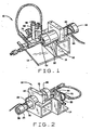
- Figure 1 is a perspective view of a liquid molding pressure control apparatus
- Figure 2 is another perspective view of the liquid molding pressure control apparatus shown in Figure 1 ;
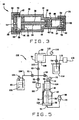
- Figure 3 is a cross-sectional side view of the liquid molding pressure control apparatus shown in Figure 1 ;
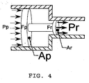
- Figure 4 is a cross-sectional side view of a piston assembly illustrating the hydraulic ram principle
- Figure 5 is a schematic diagram illustrating a system in which the liquid molding pressure control apparatus is used to increase pressure within a mold cavity according to one embodiment of the present invention
- Figure 6 is a schematic diagram illustrating a system in which the liquid molding pressure control apparatus is used to maintain pressure within a mold cavity according to another embodiment of the present invention.
- FIGS 1 and 2 are perspective views of a liquid molding pressure control apparatus generally indicated by reference number 10, according to one preferred embodiment of the present invention.
- the liquid molding control apparatus 10 may be used to boost or increase the pressure within a mold cavity while using traditional inputs (e.g., ordinary shop air at 100 PSI) during a Resin Transfer Molding (RTM) process.
- the liquid molding control apparatus 10 may be used to substantially maintain or stabilize the pressure within a resin-filled mold cavity during the resin cure cycle.
- the liquid molding pressure control apparatus 10 includes a housing 12.
- the housing 12 and one or more of the other components comprising the liquid molding pressure control apparatus 10 is supported by a support structure 14.
- the housing 12 preferably includes a first housing portion 16 and a second housing portion 18.
- the first and second housing portions 16 and 18 may be substantially cylindrical although other shapes are also possible.
- the second housing portion 18 is disposed under a heater blanket 20 and accordingly is not shown in Figure 2 .
- the second housing portion 18, however, is shown in Figure 3.
- Figure 3 is a cross-sectional side view of the liquid molding pressure control apparatus 10.
- an air cap 22 is disposed at an end of the housing 12, and a resin cap 24 is disposed at the other end of the housing 12.
- the air and resin caps 22 and 24 are threadedly engaged to the respective ends of the housing 12, as is shown in Figure 3 .
- other methods may be employed to engage the air and resin caps 22 and 24 with the housing 12 as would be obvious to those having ordinary skill in the art after having become familiar with the teachings of the present invention.
- the liquid molding pressure control apparatus 10 may further comprise an air plug 26 disposed within the first housing portion 16 adjacent the air cap 22.
- a portion 28 of the air plug 26 is disposed between portions of the first housing portion 16 and the air cap 22.
- the liquid molding pressure control apparatus 10 may further comprise a resin plug 30 disposed within the second housing portion 18 adjacent the resin cap 24.
- a portion 32 of the resin plug 30 is disposed between portions of the second housing portion 18 and the resin cap 24.
- the pressure control apparatus 10 further includes a piston assembly 34 movably disposed within the housing 12.
- the piston assembly 34 includes a shaft 36, a first or air piston 38 engaged to one end of the shaft 36, and a second or resin piston 40 engaged to the other end of the shaft 36.
- the air and resin pistons 38 and 40 are threadedly engaged to the shaft 36.
- other types of connections may be used to engage the air and resin pistons 38 and 40 with the shaft 36 as would be obvious to those having ordinary skill in the art after having become familiar with the teachings of the present invention.
- the first and second housing portions 16 and 18, respectively, are substantially tubular.
- An air chamber or cavity 42 is defined by a portion of the first housing portion 16, the air plug 26, and the air piston 38.
- a resin chamber or cavity 46 is defined by the a portion of the second housing portion 18, the resin plug 30, and the resin piston 40. Because the piston assembly 34 is movable within the housing 12, the size of the air and resin chambers 42 and 46 are dependent at least in part on the positions of the air and resin pistons 26 and 30 within the housing 12. Accordingly, the size of the air and resin chambers 42 and 46 may vary during the use of the liquid molding control apparatus 10.
- the air piston 38 may define at least one annular groove that is disposed circumferentially around the air piston 38 and that is sized to receive an o-ring 44 therein.
- the o-ring 44 comprises a Polypack o-ring, although other types of fluidic sealing members may be used.
- the resin piston 40 may define at least one annular groove that is disposed circumferentially around the resin piston 40 and that is sized to receive an o-ring 48 therein. Accordingly, the o-ring 48, when disposed within the groove, is disposed circumferentially around the resin piston 40 and thus assists the resin plug 30 with the fluidic sealing of the resin chamber 46.
- the o-ring 48 comprises a Polypack o-ring, although other types of fluidic sealing members may be used.
- the air plug 26 may define at least one groove that is sized to receive an o-ring 50 therein
- the resin plug 30 may define at least one groove that is sized to receive an o-ring 52 therein.
- the o-rings 50 and 52 are disposed circumferentially around the air plug 26 and resin plug 30, respectively. Accordingly, the o-rings 50 and 52 assist with the fluidic sealing of the air and resin chambers 42 and 46, respectively.
- the o-rings 50 and 52 comprise silicone o-rings, although other types of fluidic sealing members may be used.
- the liquid molding pressure control apparatus 10 further includes an air inlet 54 ( Figures 1 , 3, and 5 ) that is in fluid communication with the air chamber 42.
- the liquid molding pressure control apparatus 10 also includes a resin inlet/outlet 56 ( Figures 2 , 3, and 5 ) that is in fluid communication with the resin chamber 46.
- the air inlet 54 may be used to input or apply a pressurized fluid (e.g., pressurized air) from a traditional air input and regulator 58.
- the resin inlet/outlet 56 may be used to input a starting material (e.g., one-part resin, two-part resin, other multi-part resin, etc.) from a pressure pot 60 into the resin chamber 46 and to discharge the starting material from the resin chamber 46 at an elevated pressure. After exiting the resin chamber 46 through the resin inlet/outlet 56, the starting material may ultimately be injected at the elevated pressure into a mold cavity 62 of the mold or tool 64.
- a starting material e.g., one-part resin, two-part resin, other multi-part resin, etc.
- the heating apparatus comprises a heater blanket 20 disposed substantially around the second housing portion 18.
- the heater blanket 20 may be engaged to the second housing portion 18 with an elastic or bungee cord 66, although other methods of engagement are also possible.
- a particular embodiment may include the use of a multi-part resin system for which heat must be applied to prevent the resin from setting up within the resin chamber 46.
- the air regulator 58 preferably allows a user to control the pressure within the air chamber 42.
- the air regulator 58 may include a rotatable knob or valve 68 and a gauge 70. By viewing the gauge 70 and rotating the knob 68 accordingly, the user can thus control the pressure of the air chamber 42.
- a resin pressure gauge or monitor 72 may also be provided that displays the pressure at which the resin is being discharged out of the resin chamber 46, as shown in Figure 5 . Accordingly, the user may control the pressure at which the resin exits the resin chamber 46 by adjusting the pressure of the air chamber 42 with the air regulator 58.
- a resin inlet/outlet conduit or line 74 (e.g., copper tubing, nylon tubing, etc.) may be engaged with the resin cap 24 such that the resin inlet/outlet conduit 74 is in fluid communication with the resin inlet/outlet 56.
- the resin inlet/outlet conduit 74 provides a means for facilitating the introduction or resin into and the removal of resin out of the resin chamber 46.
- a depth gauge 76 may be provided.
- the air and resin pistons 38 and 40 are preferably in their respective retracted positions (i.e., position 124 shown in Figure 5 ).
- Initiation of the pressurized air into the air chamber 42 via the air inlet 54 causes the air piston 38 to move in a direction away from the air inlet 54. Because the resin piston 40 is coupled to the air piston 38 via the shaft 36, the resin piston 40 moves along with air piston 38 in a direction towards the resin outlet 56. When the resin piston 40 is moving towards the resin outlet 56, the resin piston 40 forces resin out of the resin chamber 46 and into the resin inlet/outlet conduit 74 via resin inlet/outlet 56.
- the resin piston 40 preferably has a smaller cross-sectional area than the air piston 38 so that the resin piston 40 may force the resin out of the resin chamber 46 at a pressure greater than the pressure of the pressurized air received within the air chamber 42.
- the elevated pressure at which the resin exits the resin chamber 46 will depend at least in part on the relative cross-sectional areas of the air and resin pistons 38 and 40.
- the ratio of the cross-sectional area of the air piston 38 to the cross-sectional area of the resin piston 40 is preferably about four-to-one (4-1). This allows the resin to be discharged from the housing 12 at a pressure of about 27,98 bar (400 PSI) when the pressurized air is about 6.89 bar (100 PSI)
- Figure 4 is a cross-sectional side view of an exemplary piston assembly and is used to illustrate the hydraulic ram principle.
- the piston assembly 34 of the liquid molding pressure control apparatus 10 ( Figure 3 ) is relatively rigid. Accordingly, the air piston 38 force (Fp) will be substantially equal to the resin piston 40 force (Fr).
- the air piston 38 may have a diameter of about 7.62 cm (3.0 inches) such that the air piston's 38 cross-sectional area is about 45.6 cm 2 (7.065 in 2 )
- the resin piston 40 may have a diameter of about 3.81 cm (1.5 inches) such that the resin piston's 40 cross-sectional area is about 11.40 cm 2 (1.766 in 2 ) .
- the liquid molding pressure control apparatus 10 of the preceding example can provide a ram pressure of 27.98 bar (400 PSI) while using a traditional shop input of 6.89 bar (100 PSI).
- the liquid molding pressure control apparatus 10 can be designed and built with other dimensions appropriate for achieving the desired target pressure (Pr).
- FIG. 5 is a schematic diagram of a liquid molding system 100 in which the liquid molding pressure control apparatus 10 may be used.
- the system 100 includes the liquid molding pressure control apparatus 10 shown in an initial or retracted position 124 (an extended position 126 is shown in broken lines), the air regulator 58, the resin inlet/outlet conduit 74, and resin pressure gauge 72.
- the system 100 preferably includes a pressure pot 60 containing a starting material (e.g., resin 102) therein and a pressurized fluid source or input 104 (e.g., shop air) engaged with the pressure pot 60.
- a conduit 106 is provided that allows for the resin 102 to be removed from the pressure pot 60.
- the system 100 further includes a mold or tool 64 that defines a mold cavity 62.
- the mold cavity 62 may contain a dry fabric perform 108 and be in fluid communication with conduits 110 and 112.
- Conduit 110 provides a means for facilitating the introduction of resin 102 into the mold cavity 62
- the conduit 112 provides a means for facilitating the evacuation of air from the mold cavity 62. That is, the conduit 112 may be used in conjunction with a vacuum pot 114, conduit 115, and vacuum pump 116 to draw a vacuum in the mold cavity 62.
- a gauge 118 is preferably provided on the conduit 112 so that a user can determine the pressure that is inside the mold cavity 62.
- a bleed can 120 may be provided.
- a conduit 122 may be used to dump the pressure into the bleed can 120.
- the system 100 further comprises a plurality of valves V1, V2, V3, V4, and V5 that allow for opening and closing of the various conduits 74, 106, 110, 112, and 122.
- a user may control which of the various components of the system 100 are in fluid communication with each other.
- the valves V1 through V5 may be used in the manner shown in table 1, which is a table illustrating the various steps of an exemplary operational sequence of the system 100.
- Table 1 various steps of an exemplary operational sequence of the system shown in Figure 5 St STEP VALVE POSITION V1 V2 V3 V4 V5 1 Draw vaccuum within mold cavity 62 closed closed closed open 2 Heat mold die 64 to injection temperature closed closed closed closed open 3 Hook up shop air 104 closed closed closed open 4 Inject resin 102 into mold cavity 62 open open closed closed open 5 Close conduit 122 open open closed closed 6 Build hydrostatic pressure within mold cavity 62 with pressure pot 60 open open closed closed closed closed TRANSFER CONTROL TO APPARATUS 10 7 Verify that piston assembly 34 of the apparatus 10 is in position 124 with depth gauge 76 open open closed closed closed closed 8 Fill the resin chamber 46 with resin open closed open closed closed 9 Hook up the air input 58 to the air inlet 54 open closed open closed closed 10 Remove pressure pot 60 closed closed open closed closed 11 Build pressure within air chamber 42 to 100PSI closed closed open closed closed 12 Introduce apparatus 10 to the mold die 64 closed open open closed closed 13 Monitor pressure with pressure gauge 72 and Monitor resin piston 40 position with the depth gauge 76 closed open open
- Figure 6 is a schematic diagram of a second embodiment of a liquid molding system 200 in which the liquid molding pressure control apparatus 10 may be used.
- the same reference numbers are used in Figures 5 and 7 for those components common to both the system 100 and the system 200.
- the system 200 includes a pail unloader or injector 260 instead of the pressure pot 60.
- the pail unloader 260 may include a pail or other container 262 that contains a starting material (e.g., one-part resin 264) therein.
- a pump may be used to pump the resin 264 from the pail unloader 260 into the conduit 106 and ultimately to the mold cavity 62.
- a hydraulic, mechanical, or pneumatic pump may be provided to pump the resin 264 from the pail 262 and into the conduit 106.
- the pressure within the mold cavity 62 is preferably maintained at least until the resin 264 crosslinks.
- the liquid molding pressure control apparatus 10 can be used to maintain the pressure within the mold cavity 62.
- the pail unloader 260 can be removed from the system 200 and used elsewhere.
- the various steps of an exemplary operational sequence of the system 200 is shown in tabular format in Table 2.
- Table 2 various steps of an exemplary operational sequence for the system shown in Figure 6 St STEP VALVE POSITION V1 V2 V3 V4 V5 1 Draw vaccuum within mold cavity 62 closed closed closed open 2 Heat mold die 64 to injection temperature closed closed closed closed open 3 Inject resin 102 into mold cavity 62 open open closed closed open 4 Close conduit 122 open open closed closed closed 5 Build hydrostatic pressure within mold cavity 62 with injector 260 open open closed closed closed TRANSFER CONTROL TO APPARATUS 10 6 Verify that piston assembly 34 of the apparatus 10 is in position 124 with depth gauge 76 open open closed closed closed closed 7 Fill the resin chamber 46 with resin open closed open closed closed closed 8 Hook up the air input 58 to the air inlet 54 open closed open closed closed 9 Close V1 to allow for removal of the pail unloader 260 closed closed open closed closed 10 Build pressure within air chamber 42 to a pressure slightly higher than current pressure closed closed open closed closed 10 11 Introduce apparatus 10 to the mold die 64 closed open open closed closed 12 Monitor pressure with pressure gauge 72 and Monitor resin piston 40 position
- the present invention also provides a method for use during a liquid molding process.
- the method comprises the steps of: using a liquid molding pressure control apparatus 10 having a housing 12 within which is disposed a first piston 38 and a second piston 40, to at least substantially maintain the pressure within a mold cavity 62; receiving a starting material (e.g., resin) within the housing 12 adjacent the second piston; receiving a pressurized fluid (e.g., pressurized air) within the housing 12 adjacent the first piston 38; and sizing the first and second pistons 38 and 40 such that the starting material exits the housing 12 at a pressure greater than a pressure of the pressurized fluid received within the housing 12.
- a starting material e.g., resin
- a pressurized fluid e.g., pressurized air
- the present invention provides a liquid molding pressure control device 10 that can be used during a RTM process to increase pressures within a mold cavity beyond that of a typical pressure pot or other air input.
- the liquid molding pressure control apparatus 10 may be used to maintain pressure within the mold cavity 62 after the resin transfer stage has been completed.
- the present invention When used to increased the pressure within a mold cavity, the present invention eliminates, or at least reduces, porosity problems and improves dimensional characteristics and surface quality of RTM-processed parts. Accordingly, the present invention allows for the manufacture of high-quality products, which in turn should increase productivity by reducing the number of parts that might otherwise be rejected for porosity.
- the present invention also allows for dramatic reductions in the amount of wear and tear that is typically placed on injectors during known RTM processes recognized in the art.
- an injector e.g., a pail unloader
- an injector must remain engaged with a mold cavity to maintain the pressure within the mold cavity for at least a portion of the final curing stage.
- a substantial amount of wear and tear is usually placed on the relatively expensive injector.
- the injector need not endure the wear and tear associated with maintaining mold cavity pressure during the resin curing stage.
- the present invention also allows for dramatic reductions in production cycle times of the injector per detail. Specifically, using the liquid molding pressure control apparatus 10 to maintain the mold cavity pressure during the resin curing stage instead of the injector allows the injector to be removed and thus available for additional injections elsewhere.
- the present invention also allows for cost and capital expenditure reductions. For example, less resin is consumed per RTM injection when the liquid molding pressure control apparatus 10 is used to increase the pressure within the mold cavity.
- an RTM production facility can reduce the number of costly injector systems that would otherwise be needed to support production rate requirements when one or more liquid molding pressure control apparatus 10 are used to maintain mold cavity pressures.
- the present invention may be used with any of wide range of starting materials (e.g., one-part resins, two-part resins, other multi-part resins, among other liquid moldable materials) and any of wide range of pressurized fluids (e.g., air, among others).
- the present invention may also be used in conjunction with a wide variety of injection or liquid molding processes (e.g., RTM processes, reaction injection molding (RIM) processes, among other manufacturing processes).
Landscapes
- Engineering & Computer Science (AREA)
- Mechanical Engineering (AREA)
- Chemical & Material Sciences (AREA)
- Composite Materials (AREA)
- Physics & Mathematics (AREA)
- Fluid Mechanics (AREA)
- General Engineering & Computer Science (AREA)
- Manufacturing & Machinery (AREA)
- Casting Or Compression Moulding Of Plastics Or The Like (AREA)
- Injection Moulding Of Plastics Or The Like (AREA)
Claims (19)
- System (100, 200) zur Formgebung mit Flüssigkeit, umfassend:- ein Formwerkzeug, das einen Formwerkzeughohlraum begrenzt;- eine Vorrichtung zur Versorgung mit Ausgangsmaterial; und- eine Vorrichtung (10) zur Drucksteuerung bzw. -regelung bei Formgebung mit Flüssigkeit zwecks Verwendung während eines Prozesses zur Formgebung mit Flüssigkeit, wobei die Vorrichtung zur Drucksteuerung bzw. -regelung bei Formgebung mit Flüssigkeit umfasst:- ein Gehäuse (12); und- eine innerhalb des Gehäuses beweglich eingerichtete Kolbenanordnung (34), wobei die Kolbenanordnung umfasst:- einen Schaft (36);- einen ersten Kolben (38), der mit dem Schaft in Eingriff steht; und- einen zweiten Kolben (40), der mit dem Schaft in Eingriff steht,- wobei das Gehäuse ausgelegt ist, um ein Druckfluid neben dem ersten Kolben aufzunehmen und um ein Ausgangsmaterial neben dem zweiten Kolben aufzunehmen,- wobei der erste und der zweite Kolben so bemessen sind, dass das Ausgangsmaterial das Gehäuse bei einem Druck verlässt, der größer ist als ein Druck des im Innern des Gehäuses aufgenommenen Druckfluids, und- wobei die Vorrichtung zur Drucksteuerung bzw. -regelung bei Formgebung mit Flüssigkeit einsetzbar ist, um Druck innerhalb eines Formwerkzeughohlraums im Wesentlichen aufrechtzuerhalten und um den Druck innerhalb des Formwerkzeughohlraums zu erhöhen, mit einem Drucktopf (60) oder einer Einspritzvorrichtung (260) zum Einspritzen des Ausgangsmaterials in den Formwerkzeughohlraum, lösbar verbunden mit der Vorrichtung zur Drucksteuerung bzw. - regelung bei Formgebung mit Flüssigkeit mittels zumindest eines Ventils.
- System nach Anspruch 1, wobei das Ausgangsmaterial ein Harz umfasst.
- System nach Anspruch 1, wobei das Druckfluid Druckluft umfasst.
- System nach Anspruch 1, weiterhin umfassend eine Heizvorrichtung (20) zum Beaufschlagen des Ausgangsmaterials innerhalb des Gehäuses mit Wärme.
- System nach Anspruch 1, weiterhin umfassend:- zumindest eine Kappe (22, 24), die an einem Ende des Gehäuses angeordnet ist; und- zumindest einen Stöpsel (26, 30), der innerhalb des Gehäuses neben der Kappe angeordnet ist,wobei der Stöpsel und die Kappe einen Einlass in das Gehäuse begrenzen.
- System nach Anspruch 5, wobei der Stöpsel zumindest eine Nut zum Aufnehmen eines Fluidabdichtungsteils (50, 52) in derselben begrenzt.
- System nach Anspruch 1, wobei:- der erste Kolben zumindest eine Nut zum Aufnehmen eines Fluidabdichtungsteils (44) in derselben begrenzt; und- der zweite Kolben zumindest eine Nut zum Aufnehmen eines Fluidabdichtungsteils (48) in derselben begrenzt.
- System nach Anspruch 1, weiterhin umfassend einen Tiefenmesser (76) zum Anzeigen der Positionen des ersten und des zweiten Kolbens innerhalb des Gehäuses.
- System nach Anspruch 1, wobei das Verhältnis der Querschnittsfläche des ersten Kolbens zur Querschnittsfläche des zweiten Kolbens ungefähr 4:1 beträgt.
- System nach Anspruch 1, wobei die Vorrichtung zur Versorgung mit Ausgangsmaterial einen Drucktopf (60) umfasst.
- System nach Anspruch 1, wobei die Vorrichtung zur Versorgung mit Ausgangsmaterial einen Eimer- bzw. Kübelentlader (260) umfasst.
- System nach einem der Ansprüche 1 - 11, weiterhin umfassend zumindest ein Ventil zum Steuern bzw. Regeln der fluiden Kommunikation zwischen der Vorrichtung zur Drucksteuerung bzw. -regelung bei Formgebung mit Flüssigkeit, dem Formwerkzeug und der Vorrichtung zur Versorgung mit Ausgangsmaterial.
- System nach einem der Ansprüche 1 - 12, weiterhin umfassend:- eine Ablassdose (120); und- eine Vorrichtung zum Erzeugen eines Vakuums im Formwerkzeughohlraum.
- Verfahren zur Anwendung während eines Prozesses zur Formgebung mit Flüssigkeit, wobei das Verfahren die Schritte umfasst:- Einsetzen eines Systems zur Formgebung mit Flüssigkeit nach einem der Ansprüche 1 - 13, wobei die Vorrichtung zur Drucksteuerung bzw. -regelung bei Formgebung mit Flüssigkeit ein Gehäuse (12) beinhaltet, innerhalb dessen ein erster Kolben (38) und ein zweiter Kolben (40) angeordnet sind, um den Druck innerhalb eines Formwerkzeughohlraums zumindest im Wesentlichen aufrechtzuerhalten;- Aufnehmen eines Ausgangsmaterials im Innern des Gehäuses neben dem zweiten Kolben;- Aufnehmen eines Druckfluids im Innern des Gehäuses neben dem ersten Kolben;- Bemessen des ersten und des zweiten Kolbens so, dass das Ausgangsmaterial das Gehäuse bei einem Druck verlässt, der größer ist als ein Druck des im Innern des Gehäuses aufgenommenen Druckfluids; und- Verwenden der Vorrichtung zur Drucksteuerung bzw. - regelung bei Formgebung mit Flüssigkeit, um den Formwerkzeughohlraumdruck während des Stadiums der Harzaushärtung im Wesentlichen aufrechtzuerhalten.
- Verfahren nach Anspruch 14, wobei das Aufnehmen eines Ausgangsmaterials im Innern des Gehäuses neben dem zweiten Kolben das Aufnehmen eines Harzes im Innern des Gehäuses neben dem zweiten Kolben umfasst.
- Verfahren nach Anspruch 14 oder 15, wobei das Aufnehmen von Druckfluid im Innern des Gehäuses neben dem ersten Kolben das Aufnehmen von Druckluft im Innern des Gehäuses neben dem ersten Kolben umfasst.
- Verfahren nach Anspruch 14, 15 oder 16, weiterhin umfassend den Schritt des Betätigens zumindest eines Ventils, um fluide Kommunikation zwischen der Vorrichtung zur Drucksteuerung bzw. -regelung bei Formgebung mit Flüssigkeit und dem Formwerkzeughohlraum zu steuern bzw. regeln.
- Verfahren nach einem der Ansprüche 14 - 17, weiterhin umfassend den Schritt des Verwendens eines Drucktopfes, um den Formwerkzeughohlraum und das Gehäuse mit Ausgangsmaterial zu versehen.
- Verfahren nach einem der Ansprüche 14 - 17, weiterhin umfassend den Schritt des Verwendens eines Eimer- bzw. Kübelentladers, um den Formwerkzeughohlraum mit Ausgangsmaterial zu versehen.
Applications Claiming Priority (2)
| Application Number | Priority Date | Filing Date | Title |
|---|---|---|---|
| US201839 | 2002-07-24 | ||
| US10/201,839 US20040018265A1 (en) | 2002-07-24 | 2002-07-24 | Liquid molding pressure control apparatus |
Publications (2)
| Publication Number | Publication Date |
|---|---|
| EP1384566A1 EP1384566A1 (de) | 2004-01-28 |
| EP1384566B1 true EP1384566B1 (de) | 2012-04-11 |
Family
ID=30000092
Family Applications (1)
| Application Number | Title | Priority Date | Filing Date |
|---|---|---|---|
| EP03076557A Expired - Lifetime EP1384566B1 (de) | 2002-07-24 | 2003-05-22 | Vorrichtung zur Drucksteuerung beim Formverfahren mit einer Flüssigkeit und Verwendung der selben |
Country Status (3)
| Country | Link |
|---|---|
| US (1) | US20040018265A1 (de) |
| EP (1) | EP1384566B1 (de) |
| RU (1) | RU2003123165A (de) |
Families Citing this family (5)
| Publication number | Priority date | Publication date | Assignee | Title |
|---|---|---|---|---|
| DE102011005350A1 (de) * | 2011-03-10 | 2012-09-13 | Lisa Dräxlmaier GmbH | Verfahren und Vorrichtung zur Herstellung eines Formteils mit faserverstärktem Träger und Funktionsteilen |
| EP2776234B2 (de) * | 2011-11-08 | 2020-11-04 | Safran Aircraft Engines | Druckhaltevorrichtung zur herstellung von verbundbauteilen durch spritzgiessen von harz und zugehöriges verfahren |
| EP2818294B1 (de) * | 2012-02-22 | 2019-04-10 | Toray Industries, Inc. | Rtm-verfahren |
| US11826939B2 (en) * | 2017-02-09 | 2023-11-28 | Safran Aircraft Engines | Resin injection regulator, resin injection circuit and associated methods |
| CN114046297B (zh) * | 2022-01-11 | 2022-05-10 | 成都飞机工业(集团)有限责任公司 | 一种双向伺服控制的液压增压型水锤波发生器 |
Family Cites Families (9)
| Publication number | Priority date | Publication date | Assignee | Title |
|---|---|---|---|---|
| US5316707A (en) * | 1991-09-05 | 1994-05-31 | Tempcraft, Inc. | Injection molding apparatus control system and method of injection molding |
| US5539033A (en) * | 1992-11-06 | 1996-07-23 | Minnesota Mining And Manufacturing Company | Solventless compounding and coating of non-thermoplastic hydrocarbon elastomers |
| US5518388A (en) * | 1993-12-14 | 1996-05-21 | United Technologies Corporation | Automated apparatus and method for resin transfer molding |
| US5518385A (en) * | 1994-11-09 | 1996-05-21 | United Technologies Corporation | Apparatus for resin transfer molding |
| US5770245A (en) * | 1995-09-18 | 1998-06-23 | Nissei Plastic Industrial Co., Ltd. | Preplasticizing injection machine |
| JP2928750B2 (ja) * | 1995-09-27 | 1999-08-03 | 日精樹脂工業株式会社 | 射出成形における保圧方法 |
| US5786999A (en) * | 1995-10-04 | 1998-07-28 | Barber-Colman Company | Combination control for injection molding |
| FR2750071B1 (fr) * | 1996-06-19 | 1998-09-04 | Aerospatiale | Procede de fabrication de pieces en materiau composite, par moulage par transfert de resine |
| EP0992333B1 (de) * | 1998-03-30 | 2004-10-13 | Sodick Co., Ltd. | Einspritzvorrichtung für kolbenspritzgussmaschine |
-
2002
- 2002-07-24 US US10/201,839 patent/US20040018265A1/en not_active Abandoned
-
2003
- 2003-05-22 EP EP03076557A patent/EP1384566B1/de not_active Expired - Lifetime
- 2003-07-23 RU RU2003123165/12A patent/RU2003123165A/ru not_active Application Discontinuation
Also Published As
| Publication number | Publication date |
|---|---|
| EP1384566A1 (de) | 2004-01-28 |
| RU2003123165A (ru) | 2005-01-20 |
| US20040018265A1 (en) | 2004-01-29 |
Similar Documents
| Publication | Publication Date | Title |
|---|---|---|
| US5441692A (en) | Process and apparatus for autoclave resin transfer molding | |
| US5863452A (en) | Isostatic pressure resin transfer molding | |
| US5820894A (en) | Method and apparatus for consolidating a workpiece at elevated temperature | |
| EP3265288B1 (de) | Spritzgiessmaschine | |
| JP5670381B2 (ja) | 制御された大気圧樹脂注入プロセス | |
| JP4036900B2 (ja) | コンポジット製品の成形装置 | |
| EP2227377B1 (de) | Verfahren zur herstellung eines mehrzelligen fahrzeugchassis und dadurch hergestelltes fahrzeugchassis | |
| AU651856B2 (en) | Injection molding apparatus and process | |
| EP3489001B1 (de) | Vorrichtung zur fein- und gesteuerten einstellung eines spritzgiessverfahrens und zugehöriges industrieverfahren | |
| DE69521530T2 (de) | Verbessertes verfahren zum herstellen von verbundwerkstoffen | |
| DE102017107908A1 (de) | MGI-Verfahren und entsprechendes Formwerkzeug | |
| DE102012023608B4 (de) | Verfahren und Vorrichtung zum Herstellen eines Formteils | |
| EP1384566B1 (de) | Vorrichtung zur Drucksteuerung beim Formverfahren mit einer Flüssigkeit und Verwendung der selben | |
| DE19803965A1 (de) | Verfahren zur Herstellung von Hohlkörpern aus thermoplastischen Kunststoffen mit Lang- und/oder Endlosfaserverstärkung | |
| JP4292971B2 (ja) | Frpの製造方法および製造装置 | |
| CN107073762B (zh) | 复合材料的成形方法和复合材料的成形装置 | |
| EP3168036B1 (de) | Verfahren und vorrichtung zur konsolidierung von imprägnierten faserverbundstrukturen | |
| EP2558280B1 (de) | Verfahren und vorrichtung zum formen von teilen aus verbundstoffen | |
| JP2007007910A (ja) | RTM(ResinTransferMolding)成形方法およびRTM成形用樹脂注入装置 | |
| US5788909A (en) | Elevated-temperature pneumatic apparatus and method | |
| CN107073761A (zh) | 复合材料的成形方法和复合材料的成形装置 | |
| EP1277563B1 (de) | Verfahren und Vorrichtung zur Herstellung von Formkörpern | |
| US20190047194A1 (en) | Resin injector and oil compactor for liquid composites molding | |
| CN219526515U (zh) | 一种等静压增压成型装置 | |
| JP2016083780A (ja) | 複合材料の成形方法および成形装置 |
Legal Events
| Date | Code | Title | Description |
|---|---|---|---|
| PUAI | Public reference made under article 153(3) epc to a published international application that has entered the european phase |
Free format text: ORIGINAL CODE: 0009012 |
|
| AK | Designated contracting states |
Kind code of ref document: A1 Designated state(s): AT BE BG CH CY CZ DE DK EE ES FI FR GB GR HU IE IT LI LU MC NL PT RO SE SI SK TR |
|
| AX | Request for extension of the european patent |
Extension state: AL LT LV MK |
|
| 17P | Request for examination filed |
Effective date: 20040719 |
|
| AKX | Designation fees paid |
Designated state(s): DE FR GB |
|
| 17Q | First examination report despatched |
Effective date: 20050315 |
|
| GRAP | Despatch of communication of intention to grant a patent |
Free format text: ORIGINAL CODE: EPIDOSNIGR1 |
|
| RTI1 | Title (correction) |
Free format text: LIQUID MOLDING SYSTEM COMPRISING A LIQUID MOLDING PRESSURE CONTROL APPARATUS AND METHOD OF USING THE SAME |
|
| GRAS | Grant fee paid |
Free format text: ORIGINAL CODE: EPIDOSNIGR3 |
|
| GRAA | (expected) grant |
Free format text: ORIGINAL CODE: 0009210 |
|
| AK | Designated contracting states |
Kind code of ref document: B1 Designated state(s): DE FR GB |
|
| REG | Reference to a national code |
Ref country code: GB Ref legal event code: FG4D |
|
| REG | Reference to a national code |
Ref country code: DE Ref legal event code: R096 Ref document number: 60340544 Country of ref document: DE Effective date: 20120606 |
|
| PLBE | No opposition filed within time limit |
Free format text: ORIGINAL CODE: 0009261 |
|
| STAA | Information on the status of an ep patent application or granted ep patent |
Free format text: STATUS: NO OPPOSITION FILED WITHIN TIME LIMIT |
|
| 26N | No opposition filed |
Effective date: 20130114 |
|
| REG | Reference to a national code |
Ref country code: DE Ref legal event code: R097 Ref document number: 60340544 Country of ref document: DE Effective date: 20130114 |
|
| REG | Reference to a national code |
Ref country code: FR Ref legal event code: PLFP Year of fee payment: 14 |
|
| REG | Reference to a national code |
Ref country code: FR Ref legal event code: PLFP Year of fee payment: 15 |
|
| PGFP | Annual fee paid to national office [announced via postgrant information from national office to epo] |
Ref country code: DE Payment date: 20170530 Year of fee payment: 15 Ref country code: GB Payment date: 20170530 Year of fee payment: 15 Ref country code: FR Payment date: 20170525 Year of fee payment: 15 |
|
| REG | Reference to a national code |
Ref country code: DE Ref legal event code: R119 Ref document number: 60340544 Country of ref document: DE |
|
| GBPC | Gb: european patent ceased through non-payment of renewal fee |
Effective date: 20180522 |
|
| PG25 | Lapsed in a contracting state [announced via postgrant information from national office to epo] |
Ref country code: DE Free format text: LAPSE BECAUSE OF NON-PAYMENT OF DUE FEES Effective date: 20181201 Ref country code: FR Free format text: LAPSE BECAUSE OF NON-PAYMENT OF DUE FEES Effective date: 20180531 Ref country code: GB Free format text: LAPSE BECAUSE OF NON-PAYMENT OF DUE FEES Effective date: 20180522 |
|
| P01 | Opt-out of the competence of the unified patent court (upc) registered |
Effective date: 20230503 |