EP1384562B1 - Entnahmeeinrichtung für eine Kunststoff-Spritzgiessmaschine - Google Patents
Entnahmeeinrichtung für eine Kunststoff-Spritzgiessmaschine Download PDFInfo
- Publication number
- EP1384562B1 EP1384562B1 EP03016289A EP03016289A EP1384562B1 EP 1384562 B1 EP1384562 B1 EP 1384562B1 EP 03016289 A EP03016289 A EP 03016289A EP 03016289 A EP03016289 A EP 03016289A EP 1384562 B1 EP1384562 B1 EP 1384562B1
- Authority
- EP
- European Patent Office
- Prior art keywords
- sliding carriage
- drive
- slide
- movement
- removal mechanism
- Prior art date
- Legal status (The legal status is an assumption and is not a legal conclusion. Google has not performed a legal analysis and makes no representation as to the accuracy of the status listed.)
- Expired - Lifetime
Links
Images


Classifications
-
- B—PERFORMING OPERATIONS; TRANSPORTING
- B25—HAND TOOLS; PORTABLE POWER-DRIVEN TOOLS; MANIPULATORS
- B25J—MANIPULATORS; CHAMBERS PROVIDED WITH MANIPULATION DEVICES
- B25J9/00—Program-controlled manipulators
- B25J9/02—Program-controlled manipulators characterised by movement of the arms, e.g. cartesian coordinate type
- B25J9/04—Program-controlled manipulators characterised by movement of the arms, e.g. cartesian coordinate type by rotating at least one arm, excluding the head movement itself, e.g. cylindrical coordinate type or polar coordinate type
-
- B—PERFORMING OPERATIONS; TRANSPORTING
- B25—HAND TOOLS; PORTABLE POWER-DRIVEN TOOLS; MANIPULATORS
- B25J—MANIPULATORS; CHAMBERS PROVIDED WITH MANIPULATION DEVICES
- B25J9/00—Program-controlled manipulators
- B25J9/02—Program-controlled manipulators characterised by movement of the arms, e.g. cartesian coordinate type
- B25J9/023—Cartesian coordinate type
- B25J9/026—Gantry-type
-
- B—PERFORMING OPERATIONS; TRANSPORTING
- B29—WORKING OF PLASTICS; WORKING OF SUBSTANCES IN A PLASTIC STATE IN GENERAL
- B29C—SHAPING OR JOINING OF PLASTICS; SHAPING OF MATERIAL IN A PLASTIC STATE, NOT OTHERWISE PROVIDED FOR; AFTER-TREATMENT OF THE SHAPED PRODUCTS, e.g. REPAIRING
- B29C45/00—Injection moulding, i.e. forcing the required volume of moulding material through a nozzle into a closed mould; Apparatus therefor
- B29C45/17—Component parts, details or accessories; Auxiliary operations
- B29C45/40—Removing or ejecting moulded articles
- B29C45/42—Removing or ejecting moulded articles using means movable from outside the mould between mould parts, e.g. robots
- B29C2045/4266—Robot grippers movable along three orthogonal axes
Definitions
- the invention relates to a removal device for a plastic injection molding machine for processing plastics and other plasticizable materials such as powdery or ceramic compositions according to the preamble of claim 1.
- Such a removal device is known, for example, from EP 0 359 013 B1.
- the local removal device is located above the injection molding machine, so that their frame is supported directly on the injection molding machine.
- Three carriages move a removal element in two horizontal and one vertical direction.
- the storage of the removal parts takes place behind the machine.
- Comparable devices with only one articulated arm are known from EP 0 218 101 A1, DE 36 13 074 A1 or DE 23 52 736 B2.
- WO 88/03238 A1 discloses a device for translating a rotational movement of a driver arranged eccentrically about an axis of rotation into a linear movement of a carriage, in which a plurality of drives are superimposed and, moreover, a rotary drive is provided. The movement takes place consuming in a slotted guide, so that a free pivoting of the carriage is not given.
- FIG. 3 a robot structure with three relatively movable carriages and four drives is shown, one of which is designed as a rotary drive for the third carriage relative to the second carriage.
- the present invention seeks to provide a removal device that can be used in confined spaces in conjunction with larger machines.
- a pivot drive is now provided, which thereby complements the already existing directions of movement as required and thus contribute to an accelerated movement.
- a shorter-term engagement in the injection mold is possible, so that the cycle times can be shortened.
- the so superimposed movement allows a significant reduction in the height, so that such a removal device hardly more room height required than the height of the machine itself.
- the pivot drive is constructed so that there are clear end positions by stops.
- the attacks contribute both to the accurate positioning and to a reduction in the ringing of the sampling element, especially in larger sampling facilities.
- the plastic injection molding machine is used for processing plastics and other plasticizable materials such as powdery or ceramic masses.
- the mold closing unit F is indicated in the figures, which is arranged on a machine base 14.
- the mold clamping unit F has a stationary mold carrier 11 and a movable mold carrier 12 which is cyclically movable toward and away from the stationary mold carrier by opening and closing the injection mold 15 via a closing unit, not shown in the drawing.
- Plasticized material is injected through an injection molding unit (not shown in the drawing) through the gate 11a.
- the movable mold carrier is guided along spars 13.
- a removal element 25 must be retracted into the opened injection mold, this process should take place as quickly as possible, since it determines the cycle time and thus the productivity of the machine significantly.
- the removal element 25 must be able to retract at the same time between the bars 13, which are required for the transmission of forces that occur during positive engagement and during injection. Alternatively, however, can be dispensed with such spars, as is known in tie-bar-less machines.
- a frame 20 which has support beams 22, 23 on legs 26. On both support beams 23 there are rails 21, with which a first carriage S1 is guided horizontally movable.
- the movement of the carriage S1 via the drive A1 which is fixedly mounted on the frame 20.
- the movement itself is done by drawing not shown, but known per se drive means such as belt drives, timing belts, drive chains, linear drives or comparable drive means.
- the carriage S1 is thus movable in a first movement direction x.
- a second carriage S2 is guided horizontally movably along a second movement direction y transversely to the first movement direction x.
- the movement of the second carriage S2 via a second drive A2.
- a third carriage S3 can be moved in at least one third direction of movement z by means of a third drive A3.
- the third drive A3 is arranged on the second carriage, more precisely on a pivot arm 32, which will be discussed later. Due to the movement of the third drive A3, a removal element 25 is retracted into the opened injection mold and pulled out again.
- the removal element 25 is indicated only schematically in the drawings, but these are usually known gripper.
- a pivot drive A4 is provided, which is used in addition to the actually usually already sufficient three drives.
- This pivot drive is used for pivoting the third carriage S3, so that this from the usually existing third direction of movement z, which is usually vertical in the prior art, but may also be horizontal, in one by the interaction of the drives A1, A2, A3 and the fourth axis of the fourth drive movement can be transferred.
- the interaction of the drives thus allows both the required speed and the space-saving design of the removal device, so that this as well as from Fig. 3 can be seen with a relatively small space requirement, especially as far as the room height.
- the pivot drive is formed by a belt drive. Instead, the pivot drive may e.g. but also attack directly on the pivot axis 30.
- the pivot drive A4 converts the third carriage S3, which is here a removal bar, from a position in which the third carriage is vertically movable in the third movement direction z, for example according to FIG. 4, to the horizontal pivot axis 30 into a position in FIG the third carriage S3 according to FIG. 2 is horizontally movable.
- the horizontal mobility of the third carriage S3 is preferably parallel to the first movement direction x, so that an extremely fast horizontal mobility is ensured in and out of the injection mold 15 by an interaction of the drives A1 and A3. This is illustrated in FIG. 2 by the arrows x and x 'indicating the directions of movement.
- the drives can be operated simultaneously or with a time delay.
- the pivot angle of the pivot drive A4 is 90 ° in the embodiment.
- An arm 31 mounted on the second carriage S2 carries the pivoting drive A4, which illustrates in particular FIG.
- the second carriage S2 is approximately equidistant from the pivot axis 30 via the arm 31 as the third carriage S3 via the pivot arm 32.
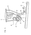
- the third carriage S3 is attached to the pivot arm 32 as shown in FIG. 5, the drive A3 facing the carriage S3 the pivot arm 32 shifts.
- the movement of the pivot drive A4 is limited by arranged on the arm 31 stops 33, so that there are clearly defined end positions.
- the pivot arm 32 has a trapezoidal projection 34 which covers a central angle of about 90 °.
- the two stops 33 are diametrically opposite on both sides of the pivot axis and thus 180 ° apart. This arrangement causes the projection 34 alternately abuts the two stops 33, which thus leads to the 90 ° pivot angle.
- the system causes the sometimes quite long slide S3 swings relatively quickly and thus can be spent specifically for removal and storage position.
- the third drive A3 must also be swiveled, the combination with the swivel drive allows significant space savings.
- the first movement direction x is transverse to the central axis m of the plastic injection molding machine 10 or, in other words, transversely to the injection axis.
- the second movement device is substantially parallel to this central axis m.
- the removal device is in the vertical projection substantially adjacent to the mold closing unit F of the plastic injection molding machine, so that the third carriage S3 is retractable horizontally into the opened injection mold 15.
- the figures show the procedure for the removal of injection molded parts.
- the third carriage S3 initially moves in the horizontal direction of movement, using the drives A1 and A3.
- the speed of retraction and extension is determined by the superimposition of the movements in the direction of movement x and x '. If the part is removed from the opened mold and the carriages S1 and S3 are retracted, the result is a position according to FIG. 3, in which the carriage S3 is still horizontal.
- a pivoting in accordance with arrow 16 and also with the cooperation of the third drive A3 pivoting in the third direction of movement z take place simultaneously via the rotary drive, so that, for example, the dashed representation of the carriage S3 corresponding representation results.
- the second drive A2 can additionally be used, which leads to a movement in the direction of movement y.
- the deposit takes place in the storage container 40 using the third drive A3, which, however, this time acts in the vertical direction.
- the third drive A3 which, however, this time acts in the vertical direction.
Landscapes
- Engineering & Computer Science (AREA)
- Robotics (AREA)
- Mechanical Engineering (AREA)
- Manufacturing & Machinery (AREA)
- Injection Moulding Of Plastics Or The Like (AREA)
- Moulds For Moulding Plastics Or The Like (AREA)
Description
- Die Erfindung betrifft eine Entnahmeeinrichtung für eine Kunststoff-Spritzgießmaschine zur Verarbeitung von Kunststoffen und anderen plastifizierbaren Materialien wie pulverigen oder keramischen Massen nach dem Oberbegriff des Anspruches 1.
- Eine derartige Entnahmeeinrichtung ist zum Beispiel aus der EP 0 359 013 B1 bekannt. Die dortige Entnahmeeinrichtung befindet sich über der Spritzgießmaschine, so dass ihr Gestell unmittelbar auf der Spritzgießmaschine abgestützt ist. Drei Schlitten bewegen dabei ein Entnahmeelement in zwei horizontalen und einer vertikalen Richtung. Die Ablage der Entnahmeteile erfolgt hinter der Maschine. Ein derartiger Aufbau bereitet jedoch bei größer werdenden Maschinen Probleme insbesondere im Hinblick auf die dafür erforderliche Raumhöhe. Vergleichbare Vorrichtungen mit nur einem Gelenkarm sind aus der EP 0 218 101 A1, DE 36 13 074 A1 oder der DE 23 52 736 B2 bekannt.
- Aus der WO 88/03238 A1 ist eine Vorrichtung zum Übersetzen einer Drehbewegung eines exzentrisch um eine Drehachse angeordneten Mitnehmers in eine Linearbewegung eines Schlitten bekannt, bei der mehrere Antriebe überlagert werden und zudem ein Drehantrieb vorgesehen ist. Die Bewegung erfolgt aufwändig in einer Kulissenführung, so dass eine freie Schwenkbarkeit des Schlittens nicht gegeben ist.
- Aus der FR 2 123 238 A ist eine Vorrichtung gemäß dem Oberbegriff des Anspruchs 1 bekannt, mit einem zwischen zwei Schlitten angeordneten Schwenkantrieb.
- Au der EP 0 081 299 A2, Fig. 3 ist eine Roboterstruktur mit drei relativ zueinander beweglichen Schlitten und vier Antrieben entnehmbar, von denen einer als Drehantrieb für den dritten Schlitten gegenüber dem zweiten Schlitten ausgebildet ist.
- Ausgehend von diesem Stand der Technik liegt der vorliegenden Erfindung die Aufgabe zugrunde, eine Entnahmeeinrichtung zu schaffen, die auch bei beengten Raumverhältnissen in Verbindung mit größeren Maschinen eingesetzt werden kann.
- Diese Aufgabe wird durch eine Entnahmeeinrichtung mit den Merkmalen des Anspruches 1 gelöst.
- Überlagert mit den bereits bekannten Antriebseinheiten für vorzugsweise orthogonal aufeinanderstehende Achsen ist jetzt ein Schwenkantrieb vorgesehen, der dadurch je nach Bedarf die ohnehin vorhandenen Bewegungsrichtungen ergänzt und damit zu einer beschleunigten Bewegung beitragen kann. Durch die Überlagerung der nun vorhandenen vier Antriebe ist ein kurzfristigerer Eingriff in die Spritzgießform möglich, so dass die Zykluszeiten verkürzt werden können. Die so überlagerte Bewegung erlaubt eine deutliche Verringerung der Bauhöhe, so dass eine derartige Entnahmeeinrichtung kaum mehr Raumhöhe benötigt als die Bauhöhe der Maschine selbst. Dennoch kann auf aufwändige Übertragungsmechanismen verzichtet werden. Es ist lediglich der Einsatz einer weiteren Antriebseinheit in Form des Schwenkantriebes erforderlich.
- Nach den Ansprüchen 7 und 8 ist der Schwenkantrieb so aufgebaut, dass sich eindeutige Endlagen durch Anschläge ergeben. Die Anschläge tragen sowohl zur genauen Positionierung als auch zu einer Reduzierung des Nachschwingens des Entnahmeelements vor allem bei größeren Entnahmeeinrichtungen bei.
- Weitere Vorteile ergeben sich aus den Unteransprüchen.
- Im folgenden wird die Erfindung anhand eines in den Figuren dargestellten Ausführungsbeispieles nähre erläutert. Es zeigen:
- Fig. 1
- eine dreidimensionale Ansicht einer Formschließeinheit einer Spritzgießmaschine mit daneben angeordneter Entnahmeeinrichtung im Ausgangszustand,
- Fig. 2
- eine Darstellung gemäss Fig. 1 mit in die Spritzgießform eingefahrenem Entnahmeelement,
- Fig. 3
- eine Darstellung gemäss Fig. 1 mit zurückgezogenem Entnahmeelement sowie - gestrichelt dargestellt - aufgerichtetem Entnahmeelement,
- Fig. 4
- eine Darstellung gemäss Fig. 1 mit Entnahmeelement in Ablageposition,
- Fig. 5
- eine vergrößerte Darstellung des am zweiten Schlitten angeordneten Schwenkantriebs.
- Die Figuren zeigen eine Entnahmeeinrichtung für eine Kunststoff-Spritzgießmaschine zur Entnahme von Spritzgießteilen aus einer geöffneten, in den Fig. 1 und 2 dargestellten Spritzgießform 15. Die Kunststoff-Spritzgießmaschine dient zur Verarbeitung von Kunststoffen und anderen plastifizierbaren Massen wie zum Beispiel pulverigen oder keramischen Massen. Von der Kunststoff-Spritzgießmaschine 10 ist in den Figuren lediglich die Formschließeinheit F angedeutet, die auf einem Maschinenfuß 14 angeordnet ist.
- Die Formschließeinheit F besitzt einen stationären Formträger 11 und einen beweglichen Formträger 12, der unter Öffnen und Schließen der Spritzgießform 15 über eine zeichnerisch nicht dargestellte Schließeinheit zyklisch auf den stationären Formträger zu und von diesem weg bewegbar ist. Plastifiziertes Material wird durch eine zeichnerisch nicht dargestellte Spritzgießeinheit durch die Angußöffnung 11a eingespritzt. Der bewegliche Formträger ist entlang von Holmen 13 geführt. Um Spritzteile aus der Spritzgießform 15 zu entnehmen, muss ein Entnahmeelement 25 in die geöffnete Spritzgießform eingefahren werden, wobei dieser Vorgang so schnell wie möglich erfolgen soll, da er die Zykluszeit und damit die Produktivität der Maschine maßgeblich bestimmt. Das Entnahmeelement 25 muss gleichzeitig auch zwischen den Holmen 13 einfahren können, die zur Übertragung der Kräfte, die beim Formschluss und beim Einspritzen entstehen, erforderlich sind. Alternativ kann jedoch auch auf derartige Holme verzichtet werden, wie dies bei holmlosen Maschinen bekannt ist.
- Im Ausführungsbeispiel neben der Spritzgießmaschine ist ein Gestell 20 vorgesehen, das auf Beinen 26 Trägerbalken 22, 23 aufweist. An beiden Trägerbalken 23 befinden sich Laufschienen 21, mit denen ein erster Schlitten S1 horizontal beweglich geführt ist. Die Bewegung des Schlittens S1 erfolgt über den Antrieb A1 der stationär am Gestell 20 befestigt ist. Die Bewegung selbst erfolgt über zeichnerisch nicht dargestellte, jedoch an sich bekannt übliche Antriebsmittel wie zum Beispiel Riemenantriebe, Zahnriemen, Antriebsketten, Linearantriebe oder vergleichbare Antriebsmittel. Der Schlitten S1 ist damit in einer ersten Bewegungsrichtung x bewegbar.
- An diesem ersten Schlitten S1 ist entlang einer zweiten Bewegungsrichtung y quer zur ersten Bewegungsrichtung x ein zweiter Schlitten S2 horizontal beweglich geführt. Die Bewegung des zweiten Schlittens S2 erfolgt über einen zweiten Antrieb A2. An diesem zweiten Schlitten S2 ist wiederum ein dritter Schlitten S3 in wenigstens einer dritten Bewegungsrichtung z mittels eines dritten Antriebes A3 bewegbar. Der dritte Antrieb A3 ist am zweiten Schlitten angeordnet, genauer gesagt an einem Schwenkarm 32, auf den noch einzugehen ist. Durch die Bewegung des dritten Antriebes A3 wird ein Entnahmeelement 25 in die geöffnete Spritzgießform eingefahren und wieder herausgefahren. Das Entnahmeelement 25 ist in den Zeichnungen lediglich schematisch angedeutet, es handelt sich hierbei jedoch üblicherweise um bekannte Greifer.
- Am zweiten Schlitten S2 ist ein Schwenkantrieb A4 vorgesehen, der zusätzlich zu den eigentlich üblicherweise bereits ausreichenden drei Antrieben eingesetzt wird. Dieser Schwenkantrieb dient zum Verschwenken des dritten Schlittens S3, so dass dieser aus der üblicherweise vorhandenen dritten Bewegungsrichtung z, die nach dem Stand der Technik bisher meist vertikal ist, aber auch horizontal sein kann, in eine durch das Zusammenspiel der Antriebe A1, A2, A3 und des Schwenkantriebs A4 überlagerte vierte Bewegungsrichtung überführbar ist. Das Zusammenspiel der Antriebe ermöglicht damit sowohl die erforderliche Geschwindigkeit als auch den platzsparenden Aufbau der Entnahmeeinrichtung, so dass diese wie auch aus Fig. 3 ersichtlich mit einem verhältnismäßig geringem Raumbedarf auskommt, vor allem was die Raumhöhe anbelangt.
- Der Schwenkantrieb ist durch einen Riemenantrieb gebildet. Stattdessen kann der Schwenkantrieb z.B. aber auch unmittelbar an der Schwenk-achse 30 angreifen. Im Ausführungsbeispiel überführt der Schwenkantrieb A4 den dritten Schlitten S3, der hier eine Entnahmestange ist, aus einer Position, in der der dritte Schlitten vertikal bewegbar in der dritten Bewegungsrichtung z zum Beispiel gemäß Figur 4 ist, um die horizontale Schwenkachse 30 in eine Position, in der der dritte Schlitten S3 gemäss Fig. 2 horizontal beweglich ist. Die horizontale Beweglichkeit des dritten Schlittens S3 ist vorzugsweise parallel zur ersten Bewegungsrichtung x, so dass durch ein Zusammenwirken der Antriebe A1 und A3 eine äußerst schnelle horizontale Beweglichkeit in die und aus der Spritzgießform 15 gewährleistet ist. Dies wird in Fig. 2 verdeutlicht durch die die Bewegungsrichtungen anzeigenden Pfeile x und x'. Je nach Ansteuerung können die Antriebe gleichzeitig oder zeitversetzt betrieben werden.
- Der Schwenkwinkel des Schwenkantriebes A4 beträgt im Ausführungsbeispiel 90°. Ein am zweiten Schlitten S2 befestigter Arm 31 trägt den Schwenkantrieb A4, was insbesondere Fig. 5 verdeutlicht. Der zweite Schlitten S2 ist über den Arm 31 ungefähr etwa gleich weit von der Schwenkachse 30 beabstandet wie der dritte Schlitten S3 über den Schwenkarm 32. Der dritte Schlitten S3 ist gemäss Fig. 5 am Schwenkarm 32 befestigt, wobei der Antrieb A3 den Schlitten S3 gegenüber dem Schwenkarm 32 verschiebt. Die Bewegung des Schwenkantriebes A4 wird durch am Arm 31 angeordnete Anschläge 33 begrenzt, so dass sich klar definierte Endlagen ergeben. Andererseits weist der Schwenkarm 32 einen trapezförmigen Vorsprung 34 auf, der einen Zentriwinkel von etwa 90° abdeckt. Die beiden Anschläge 33 sind diametral gegenüberliegend auf beiden Seiten der Schwenkachse und somit 180° voneinander entfernt angeordnet. Diese Anordnung führt dazu, dass der Vorsprung 34 wechselweise an den beiden Anschlägen 33 anliegt, was damit zu dem 90° Schwenkwinkel führt. Die Anlage bewirkt, dass der unter Umständen recht lange Schlitten S3 sich verhältnismäßig schnell ausschwingt und damit gezielt zur Entnahme als auch zur Ablageposition verbracht werden kann. Zwar muss der dritte Antrieb A3 mit verschwenkt werden, jedoch erlaubt die Kombination mit dem Schwenkantrieb eine deutliche Raumersparnis.
- Im Ausführungsbeispiel ist die erste Bewegungsrichtung x quer zur Mittelachse m der Kunststoff-Spritzgießmaschine 10 oder anders gesagt quer zur Spritzachse. Die zweite Bewegungseinrichtung ist im wesentlichen parallel zu dieser Mittelachse m. Die Entnahmeeinrichtung steht in der Vertikalprojektion im wesentlichen neben der Formschließeinheit F der Kunststoff-Spritzgießmaschine, so dass der dritte Schlitten S3 horizontal bis in die geöffnete Spritzgießform 15 einfahrbar ist.
- Die Figuren zeigen den Ablauf bei der Entnahme von Spritzgießteilen. Ausgehend von der Ausgangsposition gemäss Fig. 1 bewegt sich zunächst der dritte Schlitten S3 unter Einsatz der Antriebe A1 und A3 in horizontaler Bewegungsrichtung. Die Geschwindigkeit des Einfahrens und Ausfahrens wird bestimmt durch die Überlagerung der Bewegungen in Bewegungsrichtung x und x'. Ist das Teil aus der geöffneten Form entnommen und sind die Schlitten S1 und S3 zurückgefahren, ergibt sich eine Stellung gemäss Fig. 3, bei der also der Schlitten S3 noch horizontal steht. Falls gewünscht kann jedoch gleichzeitig über den Rotationsantrieb eine Verschwenkung gemäss Pfeil 16 sowie auch unter Mitwirkung des dritten Antriebes A3 eine Verschwenkung in der dritten Bewegungsrichtung z erfolgen, so dass sich zum Beispiel eine der gestrichelten Darstellung des Schlittens S3 entsprechende Darstellung ergibt. Dabei wird deutlich, wie groß der Abstand gegenüber den Ablagebehältem 40 ist, so dass der volle Bewegungsspielraum grundsätzlich nicht ausgenutzt werden muss. Grundsätzlich lassen sich diese Bewegungsabläufe vor allem durch die gleichzeitige Betätigung der Antriebe A1, A2 und des Schwenkantriebs A4 optimieren. Damit wird der bezweckte Betrieb eines Portals mit einem Knickarmantrieb deutlich.
- Zum Positionieren kann zusätzlich der zweite Antrieb A2 eingesetzt werden, was zu einer Bewegung in der Bewegungsrichtung y führt. Gemäss Fig. 4 erfolgt die Ablage im Ablagebehälter 40 unter Einsatz des dritten Antriebes A3, der dieses Mal jedoch in vertikaler Richtung wirkt. Deutlich wird dadurch der trotz der gering beanspruchten Raumhöhe mögliche Hub des dritten Schlittens S3 bis zum Boden.
-
- 10
- Kunststoff-Spritzgießmaschine
- 11
- stationärer Formträger
- 11a
- Angußöffnung
- 12
- beweglicher Formträger
- 13
- Holm
- 14
- Maschinenfuß
- 15
- Spritzgießform
- 16
- Pfeil
- 20
- Gestell
- 21
- Laufschiene
- 22, 23
- Trägerbalken
- 25
- Entnahmeelement
- 26
- Beine
- 30
- Schwenkachse
- 31
- Arm
- 32
- Schwenkarm
- 33
- Anschlag
- 34
- Vorsprung
- 40
- Ablagebehälter
- A1
- erster Antrieb
- A2
- zweiter Antrieb
- A3
- dritter Antrieb
- A4
- Schwenkantrieb
- S1
- erster Schlitten
- S2
- zweiter Schlitten
- S3
- dritter Schlitten
- x, y, z, x'
- Bewegungsrichtung
- F
- Formschließeinheit
Claims (13)
- Entnahmeeinrichtung für eine Kunststoff-Spritzgießmaschine (10) zur Entnahme von Spritzteilen aus der geöffneten Spritzgießform (15) mit- einem Gestell (24) mit daran befestigten Laufschienen (21),- einem an den Laufschienen (21) geführten, horizontal beweglichem ersten Schlitten (S1) und einem ersten Antrieb (A1) zur Bewegung des ersten Schlittens entlang einer ersten Bewegungsrichtung (x),- einem am ersten Schlitten (S1) entlang einer zweiten Bewegungsrichtung (y) quer zur ersten Bewegungsrichtung (x) geführten, horizontal beweglichen zweiten Schlitten (S2) und einem zweiten Antrieb (A2) zur Bewegung des zweiten Schlittens (S2),- einem am zweiten Schlitten (S2) zumindest in wenigstens einer dritten Bewegungsrichtung (z) mittels eines dritten Antriebs (A3) bewegbaren dritten Schlitten (S3) mit einem in die geöffnete Spritzgießform (15) einfahrbaren Entnahmeelement (25),dadurch gekennzeichnet, dass am zweiten Schlitten (S2) ein zusätzlicher Schwenkantrieb (A4) zum Schwenken des dritten Schlittens (S3) aus der dritten Bewegungsrichtung in eine horizontale Bewegungsrichtung vorgesehen ist.
- Entnahmeeinrichtung nach Anspruch 1, dadurch gekennzeichnet, dass der dritte Schlitten (S3) durch den Schwenkantrieb (A4) aus der dritten Bewegungsrichtung (z) in eine durch das Zusammenspiel der Antriebe (A1,A2,A3) und des Schwenkantriebs (A4) überlagerte vierte Bewegungsrichtung verschwenkbar ist.
- Entnahmeeinrichtung nach Anspruch 1 oder 2, dadurch gekennzeichnet, dass der dritte Schlitten (S3) mittels des Schwenkantriebs (A4) aus einer Position, in der der dritte Schlitten (S3) vertikal in der dritten Bewegungsrichtung (z) bewegbar ist um eine horizontale Schwenkachse (30) in eine Position überführbar ist, in der der dritte Schlitten (S3) horizontal bewegbar ist.
- Entnahmeeinrichtung nach einem der vorhergehenden Ansprüche, dadurch gekennzeichnet, dass die horizontale Beweglichkeit des dritten Schlittens (S3) parallel zur ersten Bewegungsrichtung (x) ist.
- Entnahmeeinrichtung nach einem der vorhergehenden Ansprüche, dadurch gekennzeichnet, dass zur Entnahme von Spritzteilen der erste Antrieb (A1) und der dritte Antrieb (A3) gleichzeitig betätigbar sind.
- Entnahmeeinrichtung nach einem der vorhergehenden Ansprüche, dadurch gekennzeichnet, dass der Schwenkwinkel des Schwenkantriebes (A4) 90° beträgt.
- Entnahmeeinrichtung nach einem der vorhergehenden Ansprüche, dadurch gekennzeichnet, dass ein am zweiten Schlitten (S2) befestigter Arm (31) den Schwenkantrieb (A4) trägt, wobei der zweite Schlitten (S2) über einen Arm (31) und der dritte Schlitten (S3) über einen Schwenkarm (32) gleichweit von der Schwenkachse (30) beabstandet sind.
- Entnahmeeinrichtung nach einem der vorhergehenden Ansprüche, dadurch gekennzeichnet, dass der dritte Schlitten (S3) an einem Schwenkarm (32) gehalten ist, der durch Anschläge (33) in seiner jeweiligen Endlage abgestützt ist.
- Entnahmeeinrichtung nach Anspruch 8, dadurch gekennzeichnet, dass die Anschläge (33) beiderseits der Schwenkachse (30) am Arm (31) so angeordnet sind, dass sie an den beiden Enden eines Vorsprungs (34) des Schwenkarms (32) wechselweise zur Anlage kommen.
- Entnahmeeinrichtung nach einem der vorhergehenden Ansprüche, dadurch gekennzeichnet, dass der dritte Antrieb (A3) für den dritten Schlitten (S3) am Schwenkarm (32) angeordnet ist.
- Entnahmeeinrichtung nach einem der vorhergehenden Ansprüche, dadurch gekennzeichnet, dass die erste Bewegungsrichtung (x) quer zur Mittellinie (m) der Kunststoff-Spritzgießmaschine (10) und die zweite Bewegungsrichtung (y) parallel zur Mittellinie (m) ist.
- Entnahmeeinrichtung nach einem der vorhergehenden Ansprüche, dadurch gekennzeichnet, dass die Entnahmeeinrichtung in der Vertikalprojektion neben der Formschließeinheit (F) der Spritzgießmaschine (10) angeordnet ist.
- Entnahmeeinrichtung nach einem der vorhergehenden Ansprüche, dadurch gekennzeichnet, dass der dritte Schlitten (S3) horizontal bis in die geöffnete Spritzgießform (15) einfahrbar ist.
Applications Claiming Priority (2)
| Application Number | Priority Date | Filing Date | Title |
|---|---|---|---|
| DE10234041A DE10234041B3 (de) | 2002-07-26 | 2002-07-26 | Entnahmeeinrichtung für eine Kunststoff-Spritzgießmaschine |
| DE10234041 | 2002-07-26 |
Publications (2)
| Publication Number | Publication Date |
|---|---|
| EP1384562A1 EP1384562A1 (de) | 2004-01-28 |
| EP1384562B1 true EP1384562B1 (de) | 2006-06-28 |
Family
ID=29796576
Family Applications (1)
| Application Number | Title | Priority Date | Filing Date |
|---|---|---|---|
| EP03016289A Expired - Lifetime EP1384562B1 (de) | 2002-07-26 | 2003-07-18 | Entnahmeeinrichtung für eine Kunststoff-Spritzgiessmaschine |
Country Status (4)
| Country | Link |
|---|---|
| EP (1) | EP1384562B1 (de) |
| AT (1) | ATE331601T1 (de) |
| CA (1) | CA2436020A1 (de) |
| DE (2) | DE10234041B3 (de) |
Cited By (2)
| Publication number | Priority date | Publication date | Assignee | Title |
|---|---|---|---|---|
| EP2243614A2 (de) | 2009-04-22 | 2010-10-27 | Karl Hehl | Peripheriegerät für eine Spritzgießmaschine |
| DE102014014265A1 (de) | 2013-09-27 | 2015-04-02 | Engel Austria Gmbh | Handlingvorrichtung für eine Formgebungsmaschine |
Families Citing this family (7)
| Publication number | Priority date | Publication date | Assignee | Title |
|---|---|---|---|---|
| CN103192385B (zh) * | 2013-04-22 | 2015-06-03 | 江苏康非特动力科技有限公司 | 电表组装用机械手 |
| CN103538072A (zh) * | 2013-10-22 | 2014-01-29 | 昆山中士设备工业有限公司 | 能准确确定方位的机械手 |
| WO2017182990A1 (en) * | 2016-04-21 | 2017-10-26 | Hughen Gerrard Thomas | A robotic system for carrying out an operation |
| CN105835319B (zh) * | 2016-05-03 | 2019-01-08 | 浙江品创知识产权服务有限公司 | 一种蓄电池外壳加工出料装置 |
| NL2024070B1 (en) | 2019-10-21 | 2021-06-22 | Canisius Franciscus Moens Wilhelmus | An automated in-mold label handling and product unloading device for a use with a plastic material injection molding machine |
| CN115489086B (zh) * | 2022-09-06 | 2024-12-20 | 昆山明佰精密模塑有限公司 | 一种环保型塑料注塑模具 |
| CN117227099B (zh) * | 2023-11-03 | 2024-03-08 | 广东百赞智能装备有限公司 | 一种中心转塔多色立式注塑机 |
Family Cites Families (8)
| Publication number | Priority date | Publication date | Assignee | Title |
|---|---|---|---|---|
| FR2123238A3 (en) * | 1971-05-17 | 1972-09-08 | Cusant Jeanine | Universal manipulator - esp suited to automatically loading or unloading moulds or presses |
| GB1407157A (en) * | 1973-11-28 | 1975-09-24 | Sailor Pen Co Ltd | Takeout device for injection moulding machines |
| GB2109339B (en) * | 1981-11-11 | 1986-01-29 | Norman Brian Pigott | Robot arm |
| DE3532299A1 (de) * | 1985-09-11 | 1987-03-19 | Battenfeld Kunststoffmasch | Spritzgiessmaschine mit spritzling-entnahmevorrichtung |
| DE3613074A1 (de) * | 1986-04-18 | 1987-10-29 | Battenfeld Maschfab | Spritzling-entnahmevorrichtung fuer spritzgiessmaschinen |
| DE3768269D1 (de) * | 1986-10-31 | 1991-04-04 | Veronika Waldorf | Antrieb und positionierung eines schlittens. |
| DE3830964A1 (de) * | 1988-09-12 | 1990-03-22 | Karl Hehl | Spritzgiessmaschine mit einer einrichtung zur entnahme der spritzteile aus dem spritzwerkzeug |
| JP2979404B1 (ja) * | 1998-12-08 | 1999-11-15 | 株式会社ユーシン精機 | 射出成形品取出装置の制御方法及びこれを実施する射出成形品取出装置 |
-
2002
- 2002-07-26 DE DE10234041A patent/DE10234041B3/de not_active Expired - Fee Related
-
2003
- 2003-07-18 DE DE50304028T patent/DE50304028D1/de not_active Expired - Lifetime
- 2003-07-18 AT AT03016289T patent/ATE331601T1/de not_active IP Right Cessation
- 2003-07-18 EP EP03016289A patent/EP1384562B1/de not_active Expired - Lifetime
- 2003-07-25 CA CA002436020A patent/CA2436020A1/en not_active Abandoned
Cited By (5)
| Publication number | Priority date | Publication date | Assignee | Title |
|---|---|---|---|---|
| EP2243614A2 (de) | 2009-04-22 | 2010-10-27 | Karl Hehl | Peripheriegerät für eine Spritzgießmaschine |
| DE102009018308A1 (de) | 2009-04-22 | 2010-11-11 | Karl Hehl | Peripheriegerät für eine Spritzgießmaschine |
| DE102009018308B4 (de) * | 2009-04-22 | 2014-06-12 | Renate KEINATH | Peripheriegerät für eine Spritzgießmaschine |
| DE102014014265A1 (de) | 2013-09-27 | 2015-04-02 | Engel Austria Gmbh | Handlingvorrichtung für eine Formgebungsmaschine |
| DE102014014265B4 (de) | 2013-09-27 | 2023-11-30 | Engel Austria Gmbh | Handlingvorrichtung für eine Formgebungsmaschine |
Also Published As
| Publication number | Publication date |
|---|---|
| CA2436020A1 (en) | 2004-01-26 |
| EP1384562A1 (de) | 2004-01-28 |
| DE50304028D1 (de) | 2006-08-10 |
| ATE331601T1 (de) | 2006-07-15 |
| DE10234041B3 (de) | 2004-02-19 |
Similar Documents
| Publication | Publication Date | Title |
|---|---|---|
| EP1673208B1 (de) | Horizontal-spritzgiessmaschine mit dreheinrichtung | |
| DE60313563T2 (de) | Verfahren und Vorrichtung zum Spritzgiessen von mehrkomponentigen Gegenständen | |
| DE3620175C2 (de) | ||
| EP1979148B1 (de) | Transfersystem für mehrkomponenten spritzgiessen | |
| AT409243B (de) | Blasformmaschine | |
| DE112014000406B4 (de) | Kombi-Maschine zur Blasformung, Befüllung und Versiegelung | |
| EP1384562B1 (de) | Entnahmeeinrichtung für eine Kunststoff-Spritzgiessmaschine | |
| DE2911143A1 (de) | Verfahren und vorrichtung zur herstellung von hohlkoerpern, insbesondere kunststoff-flaschen | |
| EP3959058B1 (de) | Spritzgiesseinheit für eine spritzgiessmaschine zur verarbeitung von kunststoffen | |
| WO2013072459A2 (de) | Verriegelungsvorrichtung für holme einer kunststoffverarbeitungsmaschine | |
| EP2753463B1 (de) | Werkzeug zum spritzgiessen von kunststoffteilen | |
| EP1199147B1 (de) | Etagenwerkzeug zum Spritzgiessen von Kunststoffteilen | |
| EP2691229B1 (de) | Werkzeug zum spritzgiessen von gegenständen | |
| EP3378621B1 (de) | Etagenwerkzeug | |
| DE102021121679B3 (de) | Spritzgiessvorrichtung mit drehbaren Kernabschnitten sowie Verfahren zur Herstellung von spritzgegossenen Mehrkomponenten-Kunststoffteilen | |
| WO1997012741A2 (de) | Formschliesseinheit mit einer einrichtung zur entfernung von spritzteilen | |
| EP1512512B1 (de) | Spritzgiessvorrichtung | |
| DE102011015943B4 (de) | Verriegelungsvorrichtung für Säulen einer Kunststoffverarbeitungsmaschine | |
| EP1848577B1 (de) | Spritzgiessmaschine zur verarbeitung von kunststoffen | |
| DE102011014783B4 (de) | Verriegelungsvorrichtung für Holme einer Kunststoffverarbeitungsmaschine | |
| DE19819055C1 (de) | Schwenkvorrichtung für die Spritzgießeinheit einer Spritzgießmaschine | |
| DE19631432C2 (de) | Spritzgießmaschine zur Verarbeitung von Kunststoffen und anderen plastifizierbaren Massen | |
| EP4442429A1 (de) | Werkzeug und verfahren zur herstellung eines spritzblasgeformten behältnisses | |
| AT13306U1 (de) | Schließeinheit für eine Spritzgießmaschine | |
| EP1048435A1 (de) | Verfahren und Vorrichtung zum Spritzblasformen |
Legal Events
| Date | Code | Title | Description |
|---|---|---|---|
| PUAI | Public reference made under article 153(3) epc to a published international application that has entered the european phase |
Free format text: ORIGINAL CODE: 0009012 |
|
| AK | Designated contracting states |
Kind code of ref document: A1 Designated state(s): AT BE BG CH CY CZ DE DK EE ES FI FR GB GR HU IE IT LI LU MC NL PT RO SE SI SK TR |
|
| AX | Request for extension of the european patent |
Extension state: AL LT LV MK |
|
| 17P | Request for examination filed |
Effective date: 20040722 |
|
| AKX | Designation fees paid |
Designated state(s): AT BE BG CH CY CZ DE DK EE ES FI FR GB GR HU IE IT LI LU MC NL PT RO SE SI SK TR |
|
| 17Q | First examination report despatched |
Effective date: 20050408 |
|
| GRAP | Despatch of communication of intention to grant a patent |
Free format text: ORIGINAL CODE: EPIDOSNIGR1 |
|
| GRAS | Grant fee paid |
Free format text: ORIGINAL CODE: EPIDOSNIGR3 |
|
| GRAA | (expected) grant |
Free format text: ORIGINAL CODE: 0009210 |
|
| AK | Designated contracting states |
Kind code of ref document: B1 Designated state(s): AT BE BG CH CY CZ DE DK EE ES FI FR GB GR HU IE IT LI LU MC NL PT RO SE SI SK TR |
|
| PG25 | Lapsed in a contracting state [announced via postgrant information from national office to epo] |
Ref country code: RO Free format text: LAPSE BECAUSE OF FAILURE TO SUBMIT A TRANSLATION OF THE DESCRIPTION OR TO PAY THE FEE WITHIN THE PRESCRIBED TIME-LIMIT Effective date: 20060628 Ref country code: SK Free format text: LAPSE BECAUSE OF FAILURE TO SUBMIT A TRANSLATION OF THE DESCRIPTION OR TO PAY THE FEE WITHIN THE PRESCRIBED TIME-LIMIT Effective date: 20060628 Ref country code: SI Free format text: LAPSE BECAUSE OF FAILURE TO SUBMIT A TRANSLATION OF THE DESCRIPTION OR TO PAY THE FEE WITHIN THE PRESCRIBED TIME-LIMIT Effective date: 20060628 Ref country code: CZ Free format text: LAPSE BECAUSE OF FAILURE TO SUBMIT A TRANSLATION OF THE DESCRIPTION OR TO PAY THE FEE WITHIN THE PRESCRIBED TIME-LIMIT Effective date: 20060628 Ref country code: FI Free format text: LAPSE BECAUSE OF FAILURE TO SUBMIT A TRANSLATION OF THE DESCRIPTION OR TO PAY THE FEE WITHIN THE PRESCRIBED TIME-LIMIT Effective date: 20060628 Ref country code: NL Free format text: LAPSE BECAUSE OF FAILURE TO SUBMIT A TRANSLATION OF THE DESCRIPTION OR TO PAY THE FEE WITHIN THE PRESCRIBED TIME-LIMIT Effective date: 20060628 Ref country code: IE Free format text: LAPSE BECAUSE OF FAILURE TO SUBMIT A TRANSLATION OF THE DESCRIPTION OR TO PAY THE FEE WITHIN THE PRESCRIBED TIME-LIMIT Effective date: 20060628 Ref country code: GB Free format text: LAPSE BECAUSE OF FAILURE TO SUBMIT A TRANSLATION OF THE DESCRIPTION OR TO PAY THE FEE WITHIN THE PRESCRIBED TIME-LIMIT Effective date: 20060628 |
|
| REG | Reference to a national code |
Ref country code: GB Ref legal event code: FG4D Free format text: NOT ENGLISH |
|
| REG | Reference to a national code |
Ref country code: CH Ref legal event code: EP |
|
| PG25 | Lapsed in a contracting state [announced via postgrant information from national office to epo] |
Ref country code: BE Free format text: LAPSE BECAUSE OF NON-PAYMENT OF DUE FEES Effective date: 20060731 Ref country code: MC Free format text: LAPSE BECAUSE OF NON-PAYMENT OF DUE FEES Effective date: 20060731 |
|
| REG | Reference to a national code |
Ref country code: CH Ref legal event code: NV Representative=s name: LUCHS & PARTNER PATENTANWAELTE |
|
| REG | Reference to a national code |
Ref country code: IE Ref legal event code: FG4D Free format text: LANGUAGE OF EP DOCUMENT: GERMAN |
|
| REF | Corresponds to: |
Ref document number: 50304028 Country of ref document: DE Date of ref document: 20060810 Kind code of ref document: P |
|
| PG25 | Lapsed in a contracting state [announced via postgrant information from national office to epo] |
Ref country code: DK Free format text: LAPSE BECAUSE OF FAILURE TO SUBMIT A TRANSLATION OF THE DESCRIPTION OR TO PAY THE FEE WITHIN THE PRESCRIBED TIME-LIMIT Effective date: 20060928 Ref country code: SE Free format text: LAPSE BECAUSE OF FAILURE TO SUBMIT A TRANSLATION OF THE DESCRIPTION OR TO PAY THE FEE WITHIN THE PRESCRIBED TIME-LIMIT Effective date: 20060928 |
|
| PG25 | Lapsed in a contracting state [announced via postgrant information from national office to epo] |
Ref country code: ES Free format text: LAPSE BECAUSE OF FAILURE TO SUBMIT A TRANSLATION OF THE DESCRIPTION OR TO PAY THE FEE WITHIN THE PRESCRIBED TIME-LIMIT Effective date: 20061009 |
|
| PG25 | Lapsed in a contracting state [announced via postgrant information from national office to epo] |
Ref country code: PT Free format text: LAPSE BECAUSE OF FAILURE TO SUBMIT A TRANSLATION OF THE DESCRIPTION OR TO PAY THE FEE WITHIN THE PRESCRIBED TIME-LIMIT Effective date: 20061128 |
|
| NLV1 | Nl: lapsed or annulled due to failure to fulfill the requirements of art. 29p and 29m of the patents act | ||
| GBV | Gb: ep patent (uk) treated as always having been void in accordance with gb section 77(7)/1977 [no translation filed] |
Effective date: 20060628 |
|
| REG | Reference to a national code |
Ref country code: IE Ref legal event code: FD4D |
|
| PLBE | No opposition filed within time limit |
Free format text: ORIGINAL CODE: 0009261 |
|
| STAA | Information on the status of an ep patent application or granted ep patent |
Free format text: STATUS: NO OPPOSITION FILED WITHIN TIME LIMIT |
|
| EN | Fr: translation not filed | ||
| 26N | No opposition filed |
Effective date: 20070329 |
|
| BERE | Be: lapsed |
Owner name: HEHL, KARL Effective date: 20060731 |
|
| PG25 | Lapsed in a contracting state [announced via postgrant information from national office to epo] |
Ref country code: GR Free format text: LAPSE BECAUSE OF FAILURE TO SUBMIT A TRANSLATION OF THE DESCRIPTION OR TO PAY THE FEE WITHIN THE PRESCRIBED TIME-LIMIT Effective date: 20060929 Ref country code: FR Free format text: LAPSE BECAUSE OF FAILURE TO SUBMIT A TRANSLATION OF THE DESCRIPTION OR TO PAY THE FEE WITHIN THE PRESCRIBED TIME-LIMIT Effective date: 20070511 |
|
| PG25 | Lapsed in a contracting state [announced via postgrant information from national office to epo] |
Ref country code: EE Free format text: LAPSE BECAUSE OF FAILURE TO SUBMIT A TRANSLATION OF THE DESCRIPTION OR TO PAY THE FEE WITHIN THE PRESCRIBED TIME-LIMIT Effective date: 20060628 Ref country code: BG Free format text: LAPSE BECAUSE OF FAILURE TO SUBMIT A TRANSLATION OF THE DESCRIPTION OR TO PAY THE FEE WITHIN THE PRESCRIBED TIME-LIMIT Effective date: 20060928 |
|
| PG25 | Lapsed in a contracting state [announced via postgrant information from national office to epo] |
Ref country code: HU Free format text: LAPSE BECAUSE OF FAILURE TO SUBMIT A TRANSLATION OF THE DESCRIPTION OR TO PAY THE FEE WITHIN THE PRESCRIBED TIME-LIMIT Effective date: 20061229 Ref country code: LU Free format text: LAPSE BECAUSE OF NON-PAYMENT OF DUE FEES Effective date: 20060718 Ref country code: TR Free format text: LAPSE BECAUSE OF FAILURE TO SUBMIT A TRANSLATION OF THE DESCRIPTION OR TO PAY THE FEE WITHIN THE PRESCRIBED TIME-LIMIT Effective date: 20060628 |
|
| PG25 | Lapsed in a contracting state [announced via postgrant information from national office to epo] |
Ref country code: FR Free format text: LAPSE BECAUSE OF FAILURE TO SUBMIT A TRANSLATION OF THE DESCRIPTION OR TO PAY THE FEE WITHIN THE PRESCRIBED TIME-LIMIT Effective date: 20060731 |
|
| PG25 | Lapsed in a contracting state [announced via postgrant information from national office to epo] |
Ref country code: FR Free format text: LAPSE BECAUSE OF FAILURE TO SUBMIT A TRANSLATION OF THE DESCRIPTION OR TO PAY THE FEE WITHIN THE PRESCRIBED TIME-LIMIT Effective date: 20060628 Ref country code: CY Free format text: LAPSE BECAUSE OF FAILURE TO SUBMIT A TRANSLATION OF THE DESCRIPTION OR TO PAY THE FEE WITHIN THE PRESCRIBED TIME-LIMIT Effective date: 20060628 |
|
| PGFP | Annual fee paid to national office [announced via postgrant information from national office to epo] |
Ref country code: AT Payment date: 20090723 Year of fee payment: 7 Ref country code: CH Payment date: 20090727 Year of fee payment: 7 |
|
| PGFP | Annual fee paid to national office [announced via postgrant information from national office to epo] |
Ref country code: IT Payment date: 20090729 Year of fee payment: 7 |
|
| REG | Reference to a national code |
Ref country code: CH Ref legal event code: PL |
|
| PG25 | Lapsed in a contracting state [announced via postgrant information from national office to epo] |
Ref country code: CH Free format text: LAPSE BECAUSE OF NON-PAYMENT OF DUE FEES Effective date: 20100731 Ref country code: LI Free format text: LAPSE BECAUSE OF NON-PAYMENT OF DUE FEES Effective date: 20100731 |
|
| PG25 | Lapsed in a contracting state [announced via postgrant information from national office to epo] |
Ref country code: IT Free format text: LAPSE BECAUSE OF NON-PAYMENT OF DUE FEES Effective date: 20100718 Ref country code: AT Free format text: LAPSE BECAUSE OF NON-PAYMENT OF DUE FEES Effective date: 20100718 |
|
| PG25 | Lapsed in a contracting state [announced via postgrant information from national office to epo] |
Ref country code: DE Free format text: LAPSE BECAUSE OF NON-PAYMENT OF DUE FEES Effective date: 20130201 |
|
| REG | Reference to a national code |
Ref country code: DE Ref legal event code: R119 Ref document number: 50304028 Country of ref document: DE Effective date: 20130201 |
|
| PGFP | Annual fee paid to national office [announced via postgrant information from national office to epo] |
Ref country code: DE Payment date: 20110423 Year of fee payment: 9 |