EP1383976B1 - Device for covering pools - Google Patents
Device for covering pools Download PDFInfo
- Publication number
- EP1383976B1 EP1383976B1 EP02735516A EP02735516A EP1383976B1 EP 1383976 B1 EP1383976 B1 EP 1383976B1 EP 02735516 A EP02735516 A EP 02735516A EP 02735516 A EP02735516 A EP 02735516A EP 1383976 B1 EP1383976 B1 EP 1383976B1
- Authority
- EP
- European Patent Office
- Prior art keywords
- elements
- covering
- pool
- ditch
- basin
- Prior art date
- Legal status (The legal status is an assumption and is not a legal conclusion. Google has not performed a legal analysis and makes no representation as to the accuracy of the status listed.)
- Expired - Lifetime
Links
Images


Classifications
-
- E—FIXED CONSTRUCTIONS
- E04—BUILDING
- E04H—BUILDINGS OR LIKE STRUCTURES FOR PARTICULAR PURPOSES; SWIMMING OR SPLASH BATHS OR POOLS; MASTS; FENCING; TENTS OR CANOPIES, IN GENERAL
- E04H4/00—Swimming or splash baths or pools
- E04H4/06—Safety devices; Coverings for baths
- E04H4/08—Coverings consisting of rigid elements, e.g. coverings composed of separate or connected elements
- E04H4/086—Sliding covers
Definitions
- the object of the invention is related to the technical sector of complementary equipment of individual or collective swimming pools.
- the covering device according to the invention overcomes these drawbacks in that it ensures in an economical and reliable manner, a waterproof, rigid, insulating, aesthetic, highly secure, easy to maneuver and above all invisible in open basin basin cover , and especially very compact, which allows its installation even when there is little space around the basin.
- the basin covering device of the type comprising, adjacent to one of the walls of the basin, a technical pit receiving, by stacking, carrying roofing elements stacked to be moved and guided by translation means for cover the basin, is remarkable in that said carrier cover elements are of modular character and stacked in the pit adjacent to one of the walls of the basin to be covered, a protective surface and cover covering the pit and said elements, and in that said elements are stored by successive horizontal stacking on a loader lifting platform housed in the pit, and in that said platform in its vertical lifting movement presents one by one successively said elements facing a wall of the basin, and in that a push and return member in a horizontal plane allows movement and transfer one to one of said elements from the element located in the upper horizontal part to cover or discover as the basin in its entirety without contact with water.
- the load carrying elements of the pool are coupled together and with the pushing and pulling member back when they are translated in one direction or the other, by temporary mechanical or electromechanical means.
- the lifting platform housed in the pit is constituted by a metal frame guided sliding or rolling in slides secured to the front and rear walls of the pit and operated by one or more double-acting cylinders, or by a transmission of the motor-chain type.
- the member for pushing and pulling the load-bearing elements presented at the level of the translation guiding means is constituted by a deformable parallelogram jack device temporarily connected to the push or pull carrier element. , or by motorized rack.
- the basin covering device (B) is completely invisible when it is not used, that is to say it is entirely housed in a pit (F) established for example along a transverse side of the basin and having substantially the same width as said basin.
- the pit will be about 2.5 meters wide and 5 meters long.
- the front (F1) and rear (F2) walls of the pit are equipped with two pairs of vertical rails (1-2) and (3-4) spaced in length to accommodate sliding or rolling, by any known means, a loader lifting platform (E) which consists of a metal frame (5) consisting of four lateral uprights (5a), two uprights intermediate (5b) and two lower crosspieces (5c). At the top, the uprights of the platform receive a protective surface and horizontal cover (6) to completely close the pit. This surface is advantageously made in the same way as the beaches (P) both in terms of its material and its dimensions ( Figures 1 to 13 ).
- the protective surface (6) has a belt section (6a) along three sides to rest on notched edges (F3) of the pit, while the fourth side located above the front wall (F1) of the pit, has a profile (6b) serving as a lip.
- the protective surface is fixed and independent of the platform-forming elevator platform (16). In this case, it rests on the sides of the pit leaving a space on the side of the basin for the passage of the load bearing elements.
- the uprights of the loader lifting platform internally receive profiled rails (7) for carrying the cover elements (8) of the basin via rolling means.
- Each element (8) has rollers (9) near its corners and is formed in a carrier manner with intermediate metal belt sections (8a) (8b) and in the upper part with a cover panel (8c) which can be constituted in several ways and, for example in the same material and the same presentation as the beaches.
- the panel is constituted by a triple laminated glazing in the upper part and by an aluminum sheet or equivalent absorber, the assembly forming a solar panel, in order to recover the heat input and either heat the pool , or ensure the transfer of calories to a room to be heated, by a heat pump to which can be added an electric heater, as a supplementary heat source, in case of winter need.
- a waterproof screen (10) of any known type is positioned under the intermediate profiles to collect rainwater and impurities.
- the loader lift platform (E) with its horizontal loading levels of the cover elements is vertically movable.
- one or more means of displacement (11) of the lifting platform are arranged vertically between the bottom of the pit and the frame, for example two double acting cylinders located below the bottom rails (5c).
- the actuation of the jacks drives the lifting platform upwards, with its protective surface (6), thus also the covering elements (8), the first of which above the stack then arrives at and opposite two sections (12) inserted into a groove (B1) of the walls (B2) of the basin, along the longitudinal sides of said basin.
- the profiles (12) can be combined with the pool edges.
- the cylinders (11) are stopped and the first cover member (8) must be translated on the guide rails (12) via its rollers (9).
- a horizontal push and pull member of the type with deformable parallelogram cylinder (13) for example is actuated to bring the first element of cover over the basin. This organ is located behind the pit at the level of translation of the cover elements.
- the cylinder (13) is brought back to its initial position to allow the actuation of a step cylinders (11) bringing the second covering element at the level of the profiles (12) and transferring it to the basin by the cylinder (13). This operation is repeated until the transfer of all the elements of coverage on the basin.
- the elevation of the load-bearing elements is obtained by a set of electric motors (17) and chains (18), while the translation of said elements above the basin is effected by a central rack (19) meshing with the output pinion an electric motor (20).
- rollers (9) of the load-bearing elements roll directly on the rims or the beaches of the basin, which makes it possible to cover variable shapes of basins, if care is taken to correctly size the elements.
- cover elements are coupled together and with the thrust member and back traction (13) as and when they are transferred to the basin by mechanical means of the type automatic hooks (14) or by electromechanical means of the electromagnet type (15).
- the member (13) or the assembly (19-20) pulls the last element, the connecting means are deactivated, and the said element is placed back in the lifting platform at last stage on the rails (7), then the cylinders (11) or the assembly (17-18) pull down the lifting platform with a step, the member (13) or the assembly (19- 20) is again actuated to hook the second element and bring it back to the corresponding stage of the scissor lift; after deactivation of the link, the jacks (11) or the assembly (17-18) again take the platform one step further, and so on until the last cover element.
- the lower part of the pit as well as the rear part and the lateral sides give off a space available to house other equipment such as pump, filtration which allows to concentrate the equipment economically under a small volume in continuity with the basin .
Abstract
Description
L'objet de l'invention se rattache au secteur technique des équipements complémentaires de piscines individuelles ou collectives.The object of the invention is related to the technical sector of complementary equipment of individual or collective swimming pools.
On connaît de nombreux dispositifs de couverture de piscines privées ou publiques en plein air.Many devices for covering private or public outdoor swimming pools are known.
Ces dispositifs ne sont pas satisfaisants soit sur le plan du coût et de l'encombrement tels que les auvents en éléments coulissants ou ouvrants, soit sur le plan de la sécurité et de la propreté, pour ce qui concerne les bâches enroulables et les rideaux coulissants en éléments articulés qui n'offrent par une résistance suffisante au poids d'un corps et n'assurent pas une bonne étanchéité par le fait qu'ils ne recouvrent pas complètement la piscine. D'autre part, les bâches enroulables reçoivent des impuretés lorsqu'elles sont étalées sur le bassin, et ces impuretés, lors de l'enroulement, risquent de tomber dans l'eau ce qui oblige à un nettoyage. Les rideaux coulissants posent les mêmes problèmes de propreté par suite de leur stockage dans une fosse technique adjacente au bassin. En effet, leur enroulement est effectué sur un arbre de renvoi moteur situé dans la partie supérieure de la fosse mais dans un plan au-dessus du plan d'eau. Il y a donc formation d'une bande de liaison entre la zone d'enroulement et la zone de couverture du bassin. Ainsi en fin d'enroulement, les impuretés déposées sur le rideau tombent dans le bassin.These devices are not satisfactory either in terms of cost and space such as canopies in sliding or opening elements, or in terms of safety and cleanliness, with regard to rolling tarpaulins and sliding curtains articulated elements that do not offer sufficient resistance to the weight of a body and do not provide a good seal by the fact that they do not completely cover the pool. On the other hand, the roll-up tarpaulins receive impurities when they are spread over the basin, and these impurities, during winding, may fall into the water which requires cleaning. The sliding curtains pose the same problems of cleanliness as a result of their storage in a technical pit adjacent to the pool. Indeed, their winding is performed on a motor return shaft located in the upper part of the pit but in a plane above the body of water. There is therefore formation of a connecting strip between the winding zone and the basin coverage area. Thus at the end of winding, the impurities deposited on the curtain fall into the basin.
On connaît également par le brevet autrichien
On voit que cette disposition de panneaux subit les méfaits de l'air ambiant et ne recouvre pas de manière étanche le bassin par le fait qu'ils sont situés au-dessus du bassin. Par ailleurs, leur encombrement à l'extérieur du bassin rend inesthétique l'environnement de celui-ci et prive en fait les utilisateurs d'une partie de la plage environnante.It can be seen that this arrangement of panels suffers the evils of the ambient air and does not cover the pool in a tight manner because they are located above the pool. Moreover, their size outside the pool makes the environment of the pool unsightly and effectively deprives the users of a part of the surrounding beach.
On voit encore, par le brevet français n°
On connaît par ailleurs par le brevet
Là encore, il y a encombrement de l'espace adjacent à la piscine en position de découvrement et nécessité d'une surface au moins identique à celle de la piscine ce qui n'est pas toujours réalisable.Again, there is space in the space adjacent to the pool in the uncovered position and need a surface at least identical to that of the pool which is not always feasible.
Le dispositif de couverture selon l'invention remédie à ces inconvénients en ce qu'il assure de manière économique et fiable, une couverture de bassin étanche, rigide, isolante, esthétique, de grande sécurité, facile à manoeuvrer et surtout invisible en position bassin découvert, et surtout très compacte, ce qui permet son installation même lorsqu'il y a peu de place autour du bassin.The covering device according to the invention overcomes these drawbacks in that it ensures in an economical and reliable manner, a waterproof, rigid, insulating, aesthetic, highly secure, easy to maneuver and above all invisible in open basin basin cover , and especially very compact, which allows its installation even when there is little space around the basin.
Pour cela et selon une première caractéristique, le dispositif de couverture de bassins du type comprenant, attenant à une des parois du bassin, une fosse technique recevant par empilement des éléments de couverture porteurs, empilés pour être déplacés et guidés par des moyens de translation pour couvrir le bassin, est remarquable en ce que lesdits éléments de couverture porteurs sont à caractère modulaire et empilés dans la fosse attenante à l'une des parois du bassin à recouvrir, une surface de protection et de couverture recouvrant la fosse et lesdits éléments, et en ce que lesdits éléments sont stockés par empilage horizontal successif sur une plateforme élévatrice chargeuse logées dans la fosse, et en ce que ladite plateforme dans son mouvement d'élévation vertical présente un à un successivement lesdits éléments en regard d'une paroi du bassin, et en ce qu'un organe de poussée et de retour en plan horizontal autorise le déplacement et le transfert un à un desdits éléments à partir de l'élément se trouvant en partie horizontale supérieure pour recouvrir ou découvrir au fur et à mesure le bassin dans sa totalité sans contact avec l'eau.For this purpose and according to a first feature, the basin covering device of the type comprising, adjacent to one of the walls of the basin, a technical pit receiving, by stacking, carrying roofing elements stacked to be moved and guided by translation means for cover the basin, is remarkable in that said carrier cover elements are of modular character and stacked in the pit adjacent to one of the walls of the basin to be covered, a protective surface and cover covering the pit and said elements, and in that said elements are stored by successive horizontal stacking on a loader lifting platform housed in the pit, and in that said platform in its vertical lifting movement presents one by one successively said elements facing a wall of the basin, and in that a push and return member in a horizontal plane allows movement and transfer one to one of said elements from the element located in the upper horizontal part to cover or discover as the basin in its entirety without contact with water.
Selon une autre caractéristique, les éléments porteurs de recouvrement du bassin sont attelés entre eux et avec l'organe de poussée et de traction en retour lorsqu'ils sont translatés dans un sens ou dans l'autre, par des moyens temporaires mécaniques ou électromécaniques.According to another characteristic, the load carrying elements of the pool are coupled together and with the pushing and pulling member back when they are translated in one direction or the other, by temporary mechanical or electromechanical means.
Une autre caractéristique se trouve dans le fait que la plateforme élévatrice logée dans la fosse est constituée par une ossature métallique guidée à coulissement ou à roulement dans des glissières solidaires des parois avant et arrière de la fosse et manoeuvrée par un ou des vérins double effet, ou par une transmission du type moteurs-chaînes.Another characteristic lies in the fact that the lifting platform housed in the pit is constituted by a metal frame guided sliding or rolling in slides secured to the front and rear walls of the pit and operated by one or more double-acting cylinders, or by a transmission of the motor-chain type.
Selon une autre caractéristique, l'organe de poussée et de traction en retour des éléments porteurs présentés au niveau des moyens de guidage en translation, est constitué par un dispositif de vérin à parallélogramme déformable relié temporairement à l'élément porteur à pousser ou à tirer, ou par crémaillère motorisée.According to another characteristic, the member for pushing and pulling the load-bearing elements presented at the level of the translation guiding means is constituted by a deformable parallelogram jack device temporarily connected to the push or pull carrier element. , or by motorized rack.
Ces caractéristiques et d'autres encore ressortiront de la description qui suit.These and other features will become apparent from the following description.
Pour fixer l'objet de l'invention, sans toutefois le limiter, dans les dessins annexés :
- ■ La
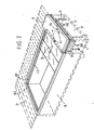
figure 1 est une vue en perspective à caractère schématique illustrant à titre d'exemple un bassin rectangulaire avec ses plages, équipé d'un dispositif selon l'invention en position escamotée (bassin découvert) dans une fosse attenante au bassin. - ■ La
figure 2 est une vue semblable à lafigure 1 illustrant le dispositif selon l'invention en cours de couverture du bassin. - ■ La
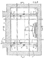
figure 3 est une vue en plan à caractère schématique illustrant le bassin et sa fosse de stockage des éléments de couverture représentés en position bassin recouvert. - ■ La
figure 4 est une vue en coupe longitudinale considérée suivant la ligne 4-4 de lafigure 3 , les éléments de couverture recouvrant le bassin. - ■ La
figure 5 est une vue semblable à lafigure 4 , les éléments de couverture étant stockés dans la fosse. - ■ La
figure 6 est une vue en coupe transversale considérée suivant la ligne 6-6 de lafigure 3 , dont lafigure 7 est une vue de détail selon A à grande échelle, montrant le guidage en translation d'un élément de couverture. - ■ La
figure 8 est une vue en plan et en coupe à caractère schématique de la fosse équipée du dispositif de couverture selon l'invention. - ■ La
figure 9 est une vue en coupe considérée suivant la ligne 9-9 de lafigure 8 , montrant le dispositif selon l'invention logé dans la fosse. - ■ La
figure 10 est une vue en coupe considérée suivant la ligne 10-10 de lafigure 8 , montrant le dispositif selon l'invention logé dans la fosse. - ■ La
figure 11 est une vue en perspective illustrant un élément de couverture selon l'invention. - ■ La
figure 12 est une vue en coupe partielle montrant deux éléments successifs de couverture reliés entre eux. - ■ La
figure 13 est une vue à plus grande échelle montrant l'attelage des éléments de couverture. - ■ La
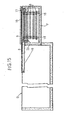
figure 14 est une vue en perspective à caractère schématique illustrant une variante de réalisation du dispositif de couverture avec un élément porteur disposé sur le bassin. - ■ La
figure 15 est une vue en coupe longitudinale correspondant à lafigure 14 . - ■ La
figure 16 est une vue en plan correspondant à lafigure 14 . - ■ La
figure 17 est une vue en coupe transversale correspondant à lafigure 14 . - ■ La
figure 18 est une vue est une vue en coupe partielle d'un élément porteur selon la variante de réalisation. - ■ La
figure 19 est une vue en coupe à grande échelle montrant la commande et le guidage en translation d'un élément porteur selon la variante de réalisation.
- ■ The
figure 1 is a schematic perspective view illustrating by way of example a rectangular basin with its beaches, equipped with a device according to the invention in the retracted position (open basin) in a pit adjacent to the basin. - ■ The
figure 2 is a view similar to thefigure 1 illustrating the device according to the invention during basin coverage. - ■ The
figure 3 is a schematic plan view illustrating the basin and its storage pit of the cover elements represented in covered basin position. - ■ The
figure 4 is a longitudinal sectional view taken along line 4-4 of thefigure 3 , covering elements covering the basin. - ■ The
figure 5 is a view similar to thefigure 4 , the cover elements being stored in the pit. - ■ The
figure 6 is a cross-sectional view taken along line 6-6 of thefigure 3 , whosefigure 7 is a detail view of A on a large scale, showing the translation guide of a cover element. - ■ The
figure 8 is a plan view and schematic sectional view of the pit equipped with the cover device according to the invention. - ■ The
figure 9 is a sectional view taken along line 9-9 of thefigure 8 , showing the device according to the invention housed in the pit. - ■ The
figure 10 is a sectional view taken along line 10-10 of thefigure 8 , showing the device according to the invention housed in the pit. - ■ The
figure 11 is a perspective view illustrating a cover element according to the invention. - ■ The
figure 12 is a partial sectional view showing two successive elements of cover interconnected. - ■ The
figure 13 is a larger-scale view showing the hitching of the roofing elements. - ■ The
figure 14 is a schematic perspective view illustrating an alternative embodiment of the cover device with a carrier element disposed on the basin. - ■ The
figure 15 is a longitudinal sectional view corresponding to thefigure 14 . - ■ The
figure 16 is a plan view corresponding to thefigure 14 . - ■ The
figure 17 is a cross-sectional view corresponding to thefigure 14 . - ■ The
figure 18 is a view is a partial sectional view of a carrier element according to the embodiment variant. - ■ The
figure 19 is a large-scale sectional view showing the control and the translational guidance of a carrier element according to the variant embodiment.
Afin de rendre plus concret l'objet de l'invention, on le décrit maintenant sous des formes non limitatives de réalisations illustrées aux figures des dessins.In order to make more concrete the object of the invention, it is now described in non-limiting embodiments of embodiments illustrated in the figures of the drawings.
Le dispositif de couverture du bassin (B) est complètement invisible lorsqu'il n'est pas mis en oeuvre, c'est-à-dire qu'il est entièrement logé dans une fosse (F) établie par exemple le long d'un côté transversal du bassin et ayant sensiblement la même largeur que ledit bassin.The basin covering device (B) is completely invisible when it is not used, that is to say it is entirely housed in a pit (F) established for example along a transverse side of the basin and having substantially the same width as said basin.
Pour fixer les idées, et seulement à titre d'exemple, pour un bassin rectangulaire de 10 mètres de longueur, et 5 mètres de largeur, la fosse aura environ 2,5 mètres de large et 5 mètres de long.To fix ideas, and only as an example, for a
Les parois avant (F1) et arrière (F2) de la fosse sont équipées de deux paires de glissières verticales (1-2) et (3-4) espacées dans la longueur pour recevoir à coulissement ou à roulement, par tous moyens connus, une plateforme élévatrice chargeuse (E) qui est constituée d'une ossature métallique (5) composée de 4 montants latéraux (5a), de deux montants intermédiaires (5b) et de deux traverses basses (5c). A la partie supérieure, les montants de la plateforme reçoivent une surface de protection et de couverture horizontale (6) destinée à obturer complètement la fosse. Cette surface est avantageusement réalisée de la même manière que les plages (P) tant au niveau de sa matière que de ses dimensions (
Dans la variante de réalisation illustrée aux
Les montants de la plateforme élévatrice chargeuse reçoivent intérieurement des rails profilés (7) destinés à porter les éléments de couverture (8) du bassin par l'intermédiaire de moyens de roulement.The uprights of the loader lifting platform internally receive profiled rails (7) for carrying the cover elements (8) of the basin via rolling means.
Dans l'exemple illustré, il y a 5 éléments de couverture de 5mètres de long et de 2 mètres de large pour recouvrir entièrement le bassin de 10 mètres de longueur par 5 mètres de largeur ; il y a donc dans ce cas 5 étages de chargement sur la plateforme (E).In the illustrated example, there are 5
Chaque élément (8) présente près de ses angles des galets de roulement (9) et est constitué de manière porteuse avec des profilés métalliques de ceinture (8a) intermédiaires (8b) et en partie supérieure avec un panneau de couverture (8c) qui peut être constitué de plusieurs façons et, par exemple dans le même matériau et la même présentation que les plages.Each element (8) has rollers (9) near its corners and is formed in a carrier manner with intermediate metal belt sections (8a) (8b) and in the upper part with a cover panel (8c) which can be constituted in several ways and, for example in the same material and the same presentation as the beaches.
D'une manière importante, le panneau est constitué par un triple vitrage feuilleté en partie supérieure et par une tôle d'aluminium ou absorbeur équivalent, l'ensemble formant un panneau solaire, afin de récupérer l'apport calorifique et, soit chauffer le bassin, soit assurer le transfert des calories vers un local à chauffer, par une pompe à chaleur à laquelle peut être adjoint un réchauffeur électrique, comme source calorifique complémentaire, en cas de besoin hivernal.Importantly, the panel is constituted by a triple laminated glazing in the upper part and by an aluminum sheet or equivalent absorber, the assembly forming a solar panel, in order to recover the heat input and either heat the pool , or ensure the transfer of calories to a room to be heated, by a heat pump to which can be added an electric heater, as a supplementary heat source, in case of winter need.
Dans le cas où les éléments (8) ne constituent pas des panneaux solaires, un écran étanche (10) de tout type connu, est positionné sous les profilés intermédiaires pour recueillir les eaux de pluie et les impuretés.In the case where the elements (8) do not constitute solar panels, a waterproof screen (10) of any known type, is positioned under the intermediate profiles to collect rainwater and impurities.
La plateforme élévatrice chargeuse (E) avec ses niveaux de chargement horizontal des éléments de couverture est mobile verticalement. Pour cela, et selon les
Arrivés dans cette position, les vérins (11) sont arrêtés et le premier élément de couverture (8) doit être translaté sur les profilés de guidage (12) par l'intermédiaire de ses galets (9). Pour cela, un organe de poussée et de traction en retour horizontale du type vérin à parallélogramme déformable (13) par exemple, est mis en action pour amener le premier élément de couverture au-dessus du bassin. Cet organe est situé en arrière de la fosse au niveau de translation des éléments de couverture ..Arrived in this position, the cylinders (11) are stopped and the first cover member (8) must be translated on the guide rails (12) via its rollers (9). For this purpose, a horizontal push and pull member of the type with deformable parallelogram cylinder (13) for example, is actuated to bring the first element of cover over the basin. This organ is located behind the pit at the level of translation of the cover elements.
Lorsque le premier élément de couverture repose entièrement sur les profilés (12), c'est à dire lorsqu'il dégage la fosse, le vérin (13) est ramené en arrière, dans sa position initiale pour permettre l'actionnement d'un pas des vérins (11) amenant le deuxième élément de couverture au niveau des profilés (12) et le transférant sur le bassin par le vérin (13). Cette opération se répète jusqu'au transfert de tous les éléments de couverture sur le bassin.When the first covering element rests entirely on the profiles (12), that is to say when it releases the pit, the cylinder (13) is brought back to its initial position to allow the actuation of a step cylinders (11) bringing the second covering element at the level of the profiles (12) and transferring it to the basin by the cylinder (13). This operation is repeated until the transfer of all the elements of coverage on the basin.
Dans la variante de réalisation illustrée aux
D'autre part, les galets (9) des éléments porteurs roulent directement sur les margelle ou les plages du bassin, ce qui permet de couvrir des formes variables de bassins, si l'on prend soin de dimensionner correctement les éléments.On the other hand, the rollers (9) of the load-bearing elements roll directly on the rims or the beaches of the basin, which makes it possible to cover variable shapes of basins, if care is taken to correctly size the elements.
A noter que les éléments de couverture sont attelés entre eux et avec l'organe de poussée et de traction en retour (13) au fur et à mesure de leur transfert sur le bassin par des moyens mécaniques du type crochets automatiques (14) ou par des moyens électromécaniques du genre électroaimants (15).Note that the cover elements are coupled together and with the thrust member and back traction (13) as and when they are transferred to the basin by mechanical means of the type automatic hooks (14) or by electromechanical means of the electromagnet type (15).
Pour la manoeuvre inverse ramenant les éléments de couverture dans la fosse, l'organe (13) ou l'ensemble (19-20) tire le dernier élément, les moyens de liaison sont désactivés, et ledit élément est replacé dans la plateforme élévatrice au dernier étage sur les rails (7), puis les vérins (11) ou l'ensemble (17-18) tirent vers le bas la plateforme élévatrice chargeuse d'un pas, l'organe (13) ou l'ensemble (19-20) est de nouveau actionné pour accrocher le deuxième élément et le ramener à l'étage correspondant de la plateforme élévatrice; après désactivation de la liaison, les vérins (11) ou l'ensemble (17-18) tirent de nouveau d'un pas la plateforme, et ainsi de suite jusqu'au dernier élément de couverture.For the opposite operation bringing the cover elements back into the pit, the member (13) or the assembly (19-20) pulls the last element, the connecting means are deactivated, and the said element is placed back in the lifting platform at last stage on the rails (7), then the cylinders (11) or the assembly (17-18) pull down the lifting platform with a step, the member (13) or the assembly (19- 20) is again actuated to hook the second element and bring it back to the corresponding stage of the scissor lift; after deactivation of the link, the jacks (11) or the assembly (17-18) again take the platform one step further, and so on until the last cover element.
A noter que la partie basse de la fosse ainsi que la partie arrière et les côtés latéraux dégagent un espace disponible pour loger d'autres équipements tels que pompe, filtration ce qui permet de concentrer économiquement les équipements sous un faible volume en continuité avec le bassin.Note that the lower part of the pit as well as the rear part and the lateral sides give off a space available to house other equipment such as pump, filtration which allows to concentrate the equipment economically under a small volume in continuity with the basin .
Les avantages ressortent bien de l'invention, on souligne encore l'invisibilité du dispositif lorsqu'il est logé dans une fosse recouverte par une surface de même nature et au même niveau que les plages du bassin, s'il y a lieu; la sécurité du dispositif composé d'éléments porteurs rigides reliés entre eux ; l'étanchéité aux impuretés par recouvrement total du bassin et par l'écran étanche des éléments de couverture ; l'isolation thermique possible par aménagement des éléments de couverture et ses possibilités de récupération d'énergie, sous forme de panneaux solaires, et l'utilisation du bassin comme réservoir thermique pour alimenter le circuit d'eau chaude de l'habitation.The advantages are clear from the invention, it is further emphasized the invisibility of the device when housed in a pit covered by a surface of the same nature and at the same level as the beaches of the basin, if any; the security of the device consisting of rigid support elements interconnected; the impurity seal by total overlap of the basin and the tight screen of the cover elements; the possible thermal insulation by arrangement of the roofing elements and its possibilities of energy recovery, in the form of solar panels, and the use of the pool as a thermal reservoir to supply the hot water circuit of the house.
Claims (13)
- Device for covering swimming pools of the type comprising, adjacent to one of the sides of a pool (B), an equipment ditch that accommodates stacked support covering elements stacked so that they can be moved and guided by translational means in order to cover the pool, characterised in that said support covering elements (8) are modular and stacked in ditch (F) adjacent to one of the sides of the pool (B) to be covered, a protective and covering surface (6) covering the ditch and said elements (8), and in that said elements are stored by successively stacking them horizontally on a loader lifting platform (E) housed in the ditch, and in that said platform, when it vertically lifts, successively presents said elements (8) one at a time facing side (F1) of pool (B), and in that a thrusting and horizontal return tractive member (13-19-20) allows displacement and transfer of said elements (8) one by one, starting with element (8) located in the upper horizontal part in order to progressively cover or expose the entire pool without contact with the water.
- Device as claimed in claim 1, characterised in that support elements (8) ate attached together and to thrusting and horizontal return tractive member (13) (19-20) when they are translationally moved in one direction or the other over the pool by temporary mechanical (14) or electromechanical (15) means.
- Device as claimed in claim 1, characterised in that loader lifting platform (E) housed in trench (F) consists of a metal framework (5) that is guided and slides or rolls on slides (1-2) and (3-4) that are attached to the front and rear sides of the ditch, said framework being designed with rails (7) that constitute staging that makes it possible to stow covering elements (8) horizontally.
- Device as claimed in claim 1, characterised in that thrusting and horizontal return tractive member for support elements (8) that are presented at a level above the pool consists of a deformable parallelogram jack (13) that is temporarily connected to the covering element (8) that is to be pushed or pulled.
- Device as claimed in claim 1, characterised in that the thrusting and horizontal return tractive member for support elements (8) that are presented at a level above the pool consists of a central rack (19) that meshes with a pinion on the output of an electric motor (20).
- Device as claimed in claim 1, characterised in that lifting of the support elements (8) stowed in platform is obtained by double-acting jacks (11).
- Device as claimed in claim 1, characterised in that lifting of the support elements (8) stowed in platform is obtained by an assembly of electric motors (17) and chains (18).
- Device as claimed in claim 1, characterised in that covering surface (6) that covers ditch (F) is attached to loader lifting platform (E) and has a profiled belt (6a) along three sides in order to rest, by forming a seal baffle, on the notched edges (F3) of the ditch with the 4th side forming the curb of the pool.
- Device as claimed in claim 1, characterised in that covering elements (8) have, in their four corners, means of rolling of the roller (9) type in order to cooperate with translational guidance means (12) built into the sides of the pool and with the profiled rails (7) supported by framework (5).
- Device as claimed in claim 1, characterised in that covering elements (8), in their four corners, have means of rolling of the roller (9) type that roll directly on the curbs or decking of the pool.
- Device as claimed in claim 1 one, characterised in that covering elements (8) consist of metallic belt profiles (8a) and intermediate profiles (8b) and their upper part consists of a covering panel (8c) that is either of the same kind as decking (P) or made of an insulating material or even a transparent material.
- Device as claimed in claim 7, characterised in that covering elements (8) are designed as solar panels with a covering panel (8c) made of laminated glass and an aluminium absorption sheet in order to collect heat input and either heat the pool or transfer energy in order to heat domestic water by using a heat pump and a heater.
- Device as claimed in claim 1, characterised in that covering elements (8) have, below covering panel (8c), a leakproof screen (10) that collects impurities and rainwater.
Applications Claiming Priority (3)
| Application Number | Priority Date | Filing Date | Title |
|---|---|---|---|
| FR0105938 | 2001-04-30 | ||
| FR0105938A FR2824095B1 (en) | 2001-04-30 | 2001-04-30 | BASIN COVERING DEVICE |
| PCT/FR2002/001477 WO2002088490A1 (en) | 2001-04-30 | 2002-04-29 | Device for covering pools |
Publications (2)
| Publication Number | Publication Date |
|---|---|
| EP1383976A1 EP1383976A1 (en) | 2004-01-28 |
| EP1383976B1 true EP1383976B1 (en) | 2010-12-29 |
Family
ID=8862951
Family Applications (1)
| Application Number | Title | Priority Date | Filing Date |
|---|---|---|---|
| EP02735516A Expired - Lifetime EP1383976B1 (en) | 2001-04-30 | 2002-04-29 | Device for covering pools |
Country Status (5)
| Country | Link |
|---|---|
| EP (1) | EP1383976B1 (en) |
| AT (1) | ATE493552T1 (en) |
| DE (1) | DE60238753D1 (en) |
| FR (1) | FR2824095B1 (en) |
| WO (1) | WO2002088490A1 (en) |
Cited By (1)
| Publication number | Priority date | Publication date | Assignee | Title |
|---|---|---|---|---|
| DE102017001927A1 (en) | 2017-03-02 | 2018-09-06 | Sven Geyger | Pool cover for a swimming pool |
Families Citing this family (12)
| Publication number | Priority date | Publication date | Assignee | Title |
|---|---|---|---|---|
| FR2843152A1 (en) * | 2002-08-05 | 2004-02-06 | Hydra Systeme | Swimming pool retractable cover comprises sliding panels with edge rollers, releasable fastenings between panel ends and stowage compartment |
| FR2843153B1 (en) * | 2002-08-05 | 2005-07-01 | Hydra Systeme | PROVISIONAL COVERING DEVICE FOR SWIMMING POOL AND SWIMMING POOL EQUIPPED WITH SAID DEVICE |
| FR2862687B1 (en) * | 2003-11-26 | 2006-01-13 | Abrisud Sccotm Chapus | DEVICE FOR DISCOVERING AND / OR COVERING THE OPENING OF A POOL BASIN FROM LOW SHELTERS OF THE TYPE JUXTAPOSED ROOFING ELEMENTS |
| FR2862685B1 (en) * | 2003-11-26 | 2006-01-13 | Abrisud Sccotm Chapus | DEVICE FOR DISCOVERING AND / OR COVERING THE OPENING OF A POOL BASIN FROM LOW SHELTERS OF THE TYPE JUXTAPOSED ROOFING ELEMENTS |
| FR2873731A1 (en) * | 2004-07-30 | 2006-02-03 | Eric Benamo | PROTECTIVE AND SECURITY DEVICE FOR SWIMMING POOL |
| FR2876724B1 (en) * | 2004-10-18 | 2007-01-12 | Pierre Fernand Besson | ROOFING DEVICE WITH REMOVABLE ELEMENTS FOR POOL RECOVERY |
| FR2894607A1 (en) * | 2005-12-12 | 2007-06-15 | Abrisud Soc Par Actions Simpli | Swimming pool basin`s opening covering and uncovering device, has stacking units including lifting units whose engagement, elevation and disengagement actions with roof elements present in storage units are controlled by action of cables |
| NL2000452C2 (en) * | 2007-01-23 | 2008-07-24 | Nepro B V | Movable floor suitable for installation above a swimming pool. |
| ES2332028B1 (en) * | 2008-03-17 | 2010-10-28 | Pere Puigdomenech Roca | POOL COVER. |
| FR2939466B1 (en) * | 2008-12-04 | 2010-12-24 | Abrisud | COVERING DEVICE FOR BASIN |
| FR2988755B1 (en) * | 2012-03-27 | 2015-03-06 | Swim Protec Ind | MOBILE COVERING DEVICE FOR A BASIN |
| CN109372292A (en) * | 2018-11-20 | 2019-02-22 | 东莞市博睿机电设备有限公司 | Covering system and its stacking covering method is laminated in pond body |
Family Cites Families (4)
| Publication number | Priority date | Publication date | Assignee | Title |
|---|---|---|---|---|
| US3094710A (en) * | 1962-08-13 | 1963-06-25 | Hoke Le Roy Austin | Swimming pool safety enclosure and cover |
| US3418667A (en) * | 1966-07-05 | 1968-12-31 | Roy Y. Powlan | Insulating swimming pool cover |
| BE839439A (en) * | 1975-03-20 | 1976-07-01 | PROCESS AND INSTALLATION FOR COVERING AND CLEARING A POOL | |
| FR2752002B1 (en) * | 1996-07-31 | 1998-10-02 | Miroiterie Romani | MOBILE PLATFORM FOR POOL OR THE LIKE |
-
2001
- 2001-04-30 FR FR0105938A patent/FR2824095B1/en not_active Expired - Fee Related
-
2002
- 2002-04-29 AT AT02735516T patent/ATE493552T1/en not_active IP Right Cessation
- 2002-04-29 DE DE60238753T patent/DE60238753D1/en not_active Expired - Lifetime
- 2002-04-29 EP EP02735516A patent/EP1383976B1/en not_active Expired - Lifetime
- 2002-04-29 WO PCT/FR2002/001477 patent/WO2002088490A1/en not_active Application Discontinuation
Cited By (1)
| Publication number | Priority date | Publication date | Assignee | Title |
|---|---|---|---|---|
| DE102017001927A1 (en) | 2017-03-02 | 2018-09-06 | Sven Geyger | Pool cover for a swimming pool |
Also Published As
| Publication number | Publication date |
|---|---|
| ATE493552T1 (en) | 2011-01-15 |
| FR2824095A1 (en) | 2002-10-31 |
| EP1383976A1 (en) | 2004-01-28 |
| DE60238753D1 (en) | 2011-02-10 |
| FR2824095B1 (en) | 2003-09-26 |
| WO2002088490A1 (en) | 2002-11-07 |
Similar Documents
| Publication | Publication Date | Title |
|---|---|---|
| EP1383976B1 (en) | Device for covering pools | |
| EP3469162B1 (en) | Collapsible pop-up structure for the rapid erection of shelters | |
| FR2488646A1 (en) | DOOR FILLING PANEL DESIGNED AS ACCORDION | |
| FR2607856A1 (en) | MOBILE STRUCTURE FOR ROOMS FOR MEETINGS OR SHOWS | |
| FR2898622A1 (en) | SWIMMING POOL COVERING DEVICE | |
| EP1687499B1 (en) | Device for uncovering and/or covering the opening to a swimming pool, for low shelters consisting of adjacent roof elements | |
| FR2568288A1 (en) | Swimming pool shelter consisting of telescopic elements which may or may not be installed on rails | |
| EP0595725A1 (en) | Flexible roller-cover panel particularly for covering an external swimming pool | |
| FR2506816A1 (en) | SOLAR FOLDING COVER FOR SWIMMING POOLS OR OTHER SIMILAR SURFACES | |
| FR2843153A1 (en) | Temporary cover for swimming pool comprises several movable panels comprising removable fixings allowing their transverse connection and engagement on pool perimeter and rollers enabling longitudinal sliding on pool perimeter | |
| EP0801183A1 (en) | Fume venting device for a long barrel-vault | |
| CH652785A5 (en) | DEVICE FOR COVERING A GAME SURFACE OR A MEETING PLACE. | |
| EP0612895B1 (en) | Sliding-roof system | |
| FR2745842A1 (en) | Retractable self-supporting cover for swimming pool | |
| EP0637523A1 (en) | Polyvalent mobile hall and trailer for transporting a telescopic body | |
| EP1029445A1 (en) | Modular shading and thermal protection device consisting of panels | |
| FR3049973A1 (en) | ABRI, IN PARTICULAR BIOCLIMATIC PERGOLA, WITH MODULARITY OF PERFECTED LUMINOSITY | |
| EP0076349A1 (en) | Articulated, insulating and translucent panel | |
| EP0516517A1 (en) | Mobile deployable construction | |
| WO2017109380A1 (en) | Telescopic unit for storing a cover element inside a storage room | |
| FR2729176A1 (en) | Automatic rigid cover for swimming pool | |
| FR2491120A1 (en) | Oven door seal clip - has resilient body which pierces seal and locates over wire attached to internal seal surface | |
| EP0383709A1 (en) | Moving closure means for a wall opening | |
| FR2952099A1 (en) | Residential building extension, has wall passing solar ray in upper space, where solar ray is entered in lower space and body of building to improve natural lighting level of lower space and body and enlarge catchment level of solar heat | |
| FR3123673A1 (en) | Installation with a flexible space, especially around a swimming pool |
Legal Events
| Date | Code | Title | Description |
|---|---|---|---|
| PUAI | Public reference made under article 153(3) epc to a published international application that has entered the european phase |
Free format text: ORIGINAL CODE: 0009012 |
|
| 17P | Request for examination filed |
Effective date: 20031013 |
|
| AK | Designated contracting states |
Kind code of ref document: A1 Designated state(s): AT BE CH CY DE DK ES FI FR GB GR IE IT LI LU MC NL PT SE TR |
|
| AX | Request for extension of the european patent |
Extension state: AL LT LV MK RO SI |
|
| 17Q | First examination report despatched |
Effective date: 20070308 |
|
| GRAP | Despatch of communication of intention to grant a patent |
Free format text: ORIGINAL CODE: EPIDOSNIGR1 |
|
| GRAS | Grant fee paid |
Free format text: ORIGINAL CODE: EPIDOSNIGR3 |
|
| GRAA | (expected) grant |
Free format text: ORIGINAL CODE: 0009210 |
|
| AK | Designated contracting states |
Kind code of ref document: B1 Designated state(s): AT BE CH DE LI |
|
| REG | Reference to a national code |
Ref country code: CH Ref legal event code: EP |
|
| REF | Corresponds to: |
Ref document number: 60238753 Country of ref document: DE Date of ref document: 20110210 Kind code of ref document: P |
|
| REG | Reference to a national code |
Ref country code: DE Ref legal event code: R096 Ref document number: 60238753 Country of ref document: DE Effective date: 20110210 |
|
| PG25 | Lapsed in a contracting state [announced via postgrant information from national office to epo] |
Ref country code: AT Free format text: LAPSE BECAUSE OF FAILURE TO SUBMIT A TRANSLATION OF THE DESCRIPTION OR TO PAY THE FEE WITHIN THE PRESCRIBED TIME-LIMIT Effective date: 20101229 |
|
| PLBE | No opposition filed within time limit |
Free format text: ORIGINAL CODE: 0009261 |
|
| STAA | Information on the status of an ep patent application or granted ep patent |
Free format text: STATUS: NO OPPOSITION FILED WITHIN TIME LIMIT |
|
| 26N | No opposition filed |
Effective date: 20110930 |
|
| REG | Reference to a national code |
Ref country code: DE Ref legal event code: R097 Ref document number: 60238753 Country of ref document: DE Effective date: 20110930 |
|
| PGFP | Annual fee paid to national office [announced via postgrant information from national office to epo] |
Ref country code: CH Payment date: 20190315 Year of fee payment: 18 |
|
| PGFP | Annual fee paid to national office [announced via postgrant information from national office to epo] |
Ref country code: DE Payment date: 20190218 Year of fee payment: 18 |
|
| PGFP | Annual fee paid to national office [announced via postgrant information from national office to epo] |
Ref country code: BE Payment date: 20190426 Year of fee payment: 18 |
|
| REG | Reference to a national code |
Ref country code: DE Ref legal event code: R119 Ref document number: 60238753 Country of ref document: DE |
|
| REG | Reference to a national code |
Ref country code: CH Ref legal event code: PL |
|
| PG25 | Lapsed in a contracting state [announced via postgrant information from national office to epo] |
Ref country code: CH Free format text: LAPSE BECAUSE OF NON-PAYMENT OF DUE FEES Effective date: 20200430 Ref country code: LI Free format text: LAPSE BECAUSE OF NON-PAYMENT OF DUE FEES Effective date: 20200430 Ref country code: DE Free format text: LAPSE BECAUSE OF NON-PAYMENT OF DUE FEES Effective date: 20201103 |
|
| REG | Reference to a national code |
Ref country code: BE Ref legal event code: MM Effective date: 20200430 |
|
| PG25 | Lapsed in a contracting state [announced via postgrant information from national office to epo] |
Ref country code: BE Free format text: LAPSE BECAUSE OF NON-PAYMENT OF DUE FEES Effective date: 20200430 |