EP1383705B1 - Liquid injector system - Google Patents
Liquid injector system Download PDFInfo
- Publication number
- EP1383705B1 EP1383705B1 EP02718370A EP02718370A EP1383705B1 EP 1383705 B1 EP1383705 B1 EP 1383705B1 EP 02718370 A EP02718370 A EP 02718370A EP 02718370 A EP02718370 A EP 02718370A EP 1383705 B1 EP1383705 B1 EP 1383705B1
- Authority
- EP
- European Patent Office
- Prior art keywords
- container
- liquid
- nozzle
- valve
- cap
- Prior art date
- Legal status (The legal status is an assumption and is not a legal conclusion. Google has not performed a legal analysis and makes no representation as to the accuracy of the status listed.)
- Expired - Lifetime
Links
Images


Classifications
-
- B—PERFORMING OPERATIONS; TRANSPORTING
- B67—OPENING, CLOSING OR CLEANING BOTTLES, JARS OR SIMILAR CONTAINERS; LIQUID HANDLING
- B67D—DISPENSING, DELIVERING OR TRANSFERRING LIQUIDS, NOT OTHERWISE PROVIDED FOR
- B67D7/00—Apparatus or devices for transferring liquids from bulk storage containers or reservoirs into vehicles or into portable containers, e.g. for retail sale purposes
- B67D7/02—Apparatus or devices for transferring liquids from bulk storage containers or reservoirs into vehicles or into portable containers, e.g. for retail sale purposes for transferring liquids other than fuel or lubricants
- B67D7/0227—Apparatus or devices for transferring liquids from bulk storage containers or reservoirs into vehicles or into portable containers, e.g. for retail sale purposes for transferring liquids other than fuel or lubricants by an ejection plunger
-
- B—PERFORMING OPERATIONS; TRANSPORTING
- B65—CONVEYING; PACKING; STORING; HANDLING THIN OR FILAMENTARY MATERIAL
- B65D—CONTAINERS FOR STORAGE OR TRANSPORT OF ARTICLES OR MATERIALS, e.g. BAGS, BARRELS, BOTTLES, BOXES, CANS, CARTONS, CRATES, DRUMS, JARS, TANKS, HOPPERS, FORWARDING CONTAINERS; ACCESSORIES, CLOSURES, OR FITTINGS THEREFOR; PACKAGING ELEMENTS; PACKAGES
- B65D47/00—Closures with filling and discharging, or with discharging, devices
- B65D47/04—Closures with discharging devices other than pumps
- B65D47/20—Closures with discharging devices other than pumps comprising hand-operated members for controlling discharge
- B65D47/24—Closures with discharging devices other than pumps comprising hand-operated members for controlling discharge with poppet valves or lift valves, i.e. valves opening or closing a passageway by a relative motion substantially perpendicular to the plane of the seat
- B65D47/248—Closures with discharging devices other than pumps comprising hand-operated members for controlling discharge with poppet valves or lift valves, i.e. valves opening or closing a passageway by a relative motion substantially perpendicular to the plane of the seat the valve being opened or closed by imparting a motion to the valve stem
-
- B—PERFORMING OPERATIONS; TRANSPORTING
- B65—CONVEYING; PACKING; STORING; HANDLING THIN OR FILAMENTARY MATERIAL
- B65D—CONTAINERS FOR STORAGE OR TRANSPORT OF ARTICLES OR MATERIALS, e.g. BAGS, BARRELS, BOTTLES, BOXES, CANS, CARTONS, CRATES, DRUMS, JARS, TANKS, HOPPERS, FORWARDING CONTAINERS; ACCESSORIES, CLOSURES, OR FITTINGS THEREFOR; PACKAGING ELEMENTS; PACKAGES
- B65D81/00—Containers, packaging elements, or packages, for contents presenting particular transport or storage problems, or adapted to be used for non-packaging purposes after removal of contents
- B65D81/32—Containers, packaging elements, or packages, for contents presenting particular transport or storage problems, or adapted to be used for non-packaging purposes after removal of contents for packaging two or more different materials which must be maintained separate prior to use in admixture
- B65D81/3255—Containers provided with a piston or a movable bottom, and permitting admixture within the container
-
- B—PERFORMING OPERATIONS; TRANSPORTING
- B65—CONVEYING; PACKING; STORING; HANDLING THIN OR FILAMENTARY MATERIAL
- B65D—CONTAINERS FOR STORAGE OR TRANSPORT OF ARTICLES OR MATERIALS, e.g. BAGS, BARRELS, BOTTLES, BOXES, CANS, CARTONS, CRATES, DRUMS, JARS, TANKS, HOPPERS, FORWARDING CONTAINERS; ACCESSORIES, CLOSURES, OR FITTINGS THEREFOR; PACKAGING ELEMENTS; PACKAGES
- B65D83/00—Containers or packages with special means for dispensing contents
- B65D83/0005—Containers or packages provided with a piston or with a movable bottom or partition having approximately the same section as the container
-
- B—PERFORMING OPERATIONS; TRANSPORTING
- B67—OPENING, CLOSING OR CLEANING BOTTLES, JARS OR SIMILAR CONTAINERS; LIQUID HANDLING
- B67D—DISPENSING, DELIVERING OR TRANSFERRING LIQUIDS, NOT OTHERWISE PROVIDED FOR
- B67D7/00—Apparatus or devices for transferring liquids from bulk storage containers or reservoirs into vehicles or into portable containers, e.g. for retail sale purposes
- B67D7/02—Apparatus or devices for transferring liquids from bulk storage containers or reservoirs into vehicles or into portable containers, e.g. for retail sale purposes for transferring liquids other than fuel or lubricants
- B67D7/0288—Container connection means
- B67D7/0294—Combined with valves
Definitions
- This invention relates to a liquid injector system and, more particularly, to a hand-held liquid injector system.
- the present invention has reference to such a system for use in dispensing a concentrated beverage, for example a soft drink concentrate, into a dilutant, e.g. water.
- a concentrated beverage for example a soft drink concentrate
- a dilutant e.g. water
- dispensers for example liquid soap dispensers, having a pump mechanism for releasing liquid contents from a container.
- hand-held devices do not provide for transfer of liquid from a container in a controlled manner.
- USP 4 453 651 concerns a dispenser including a cartridge containing a fluent substance, for example a mastic, the discharge of which is effected by a piston pressing on the substance which is released through a valve mounted within the cartridge.
- the valve is operable by a nozzle pressing against it from outside the container.
- a hand-held liquid injector system including a liquid injector comprising a container for containing a liquid and having an outlet, a manually operable piston slidable in the container and a valve member for controlling flow of liquid through the outlet from the container and adapted for operation inwardly of the container, the arrangement being such that operation of the piston causes the liquid to be subjected to pressure whereby, when the valve member is operated, at least some of the liquid is transferred from the container under pressure in a controlled manner, and stopper means within the container for limiting the movement of the valve member.
- the system may also include nozzle means for engaging the valve member.
- the nozzle means may be a separate element which may be releasably accommodated and stored on an external part of the system when not in use.
- the nozzle means may be permanently associated with the valve member.
- the nozzle means may be integral with a cap device for a second container.
- an injector 10 comprising a cylindrical container 11 which is formed of plastics material, which is open at one end portion thereof and which is formed as a cowl 12 at a remote end portion thereof, the cowl 12 having a rectangular opening 13.
- the container 11 is provided with a cylindrical liner 14 an end portion of which is turned outwardly to provide a circumferential rim 15 and a remote end portion of which is turned inwardly to provide opposite facing finger-like abutment surfaces 16, inner surfaces of which define an aperture 17 which is located coaxially with a central longitudinal axis of the container 11.
- the liner 14 is formed of plastics material portions of which are formed as elongate leaf springs 18. The liner 14 is inserted axially into the container 11 through the open end thereof so that the circumferential rim 15 thereof engages an adjacent end wall of the container 11 and lower end portions of the leaf springs 18 extend through the aperture 17.
- the liner 14 has received therein a piston 19, one end portion of which is provided with a circumferentially extending rim 20 and a flat end wall 21. An opposite end portion of the piston 19 remote from the end wall 21 is tapered, as shown at 22.
- the container 11 has slidably located in the opening 13 thereof a rectangular valve 23 having inlet ports 24 and an outlet port 25, an upper portion of the valve 23 having an outward peripherally extending rim 26.
- the arrangement is such that in a fully inward position of the valve 23, the valve 23 abuts the abutment surfaces 16 and in a fully outward position of the valve 23, the rim 26 of the valve 23 abuts an inner circumferential margin of the opening 13.
- the leaf springs 18 flex arcuately in opposite directions one to another, as shown in Figure 1. Also as shown in Figure 1, the dimensions of the valve 23 are such that, when the valve 23 is in abutment with the abutment surfaces 16, a lower end portion of the valve 23 is located in the opening 13 of the container 11.
- the liner 14 does not cover the whole of an inner surface of the container 11 and the container 11 is of transparent or translucent material so that contents in the container 11 are visible from outside of the container 11.
- the container 11 is marked with a longitudinally extending scale (not shown) having gradations indicative of calories.
- a nozzle 27 which is generally of cylindrical configuration having an upper end portion 28 and a lower skirt portion 29.
- the upper end portion 28 has a pair of upwardly extending spaced parallel projections 30 which are of reduced dimension compared with a corresponding transverse dimension of the upper end portion 28 thereby providing a pair of abutment surfaces 31 adjacent corresponding end portions of the projections 30.
- the skirt portion 29 is provided with a pair of finger grips, one of which is shown at 32.
- the concentrated liquid in the container 11 is primed by pressing downwardly on the flat end wall 21 of the piston 19 so as to push the piston 19 into the cylinder 11 and apply downward pressure on the concentrated liquid.
- the skirt portion 29 of the nozzle 27 is then seated on a cap 33 (see Figure 6) or a cap 44 (see Figure 7) which is located on an open neck of a bottle (not shown) containing a liquid which is to receive at least some of the concentrated liquid contained in the container 11.
- the projections 30 of the nozzle 27 are located in the opening 13 of the container 11 such that the projections 30 enter into the outlet port 25 of the valve 23 and the abutment surfaces 31 of the nozzle 27 engage a lower surface of the valve 23.
- the injector 10 is then moved toward the nozzle 27 thereby effecting relative movement between the injector 10 and the nozzle 27 such that the valve 23 moves inwardly of the container 11 against the bias of the leaf springs 18 and some of the concentrated liquid in the container 11 is forced through the inlet ports 24 and the outlet port 25 of the valve 23 outwardly of the container 11 and into bottle.
- the amount of concentrated liquid which is transferred is controlled by the pressure applied to the piston 19.
- the nozzle 27 is removed and the valve 23 is urged by the leaf springs 18 to the closed position.
- the movement of the piston 19 ensures that transfer of the concentrated liquid is effected in a controlled manner.
- the level of the concentrated liquid in the container 11 lowers relative to the scale providing an indication as to the number of calories which have been transferred to the bottle.
- the process may be repeated so as to ensure that a required dosage may be transferred in a controlled manner.
- An adapter (not shown) may be provided having the same shape as the nozzle 27 but without the lower skirt portion 29. Such an adapter would be for use in operating the injector 10 so as to supply contents of the injector 10 into an open container, such as a cup or a glass.
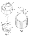
- a cap 33 for use with the injector 10 comprising two components, being an outer portion 34 and an inner portion 35.
- the outer portion 34 includes an aperture 36 and a nozzle 37, the latter corresponding to the upper end portion 28 of the nozzle 27.
- the inner portion 35 of the cap 33 comprises a pair of discs 38, 39 each of which is provided with a pair of apertures 40, 41, for selectively locating in register with the nozzle 37, and an aperture 42, for locating in register with the aperture 36 in the outer portion 34.
- the discs 38, 39 are spaced one from another by a centering mechanism 43 and the discs 38, 39 and the centering mechanism 43 are secured one to another forming a single unit.
- the centering mechanism 43 comprises one of a pair of opposed tracks, the other being located on an inner surface of the outer portion 34 of the cap 33. Each of the tracks comprises a series of undulations and the opposed tracks engage one with another.
- the arrangement is such that the inner portion 35 is located inside the outer portion 34 of the cap 33 and when the cap 33 is located on an open neck of a bottle, the cap 33 may be turned to an "inject" mode, whereby the aperture 40 is in communication with the nozzle 37 and the aperture 36 of the outer portion 34 is in register with the apertures 42 of the inner portion 35 to provide for displacement of air outwardly from inside of the bottle when the contents from the injector 10 are injected into the bottle or in a "ready to drink” mode whereby the aperture 41 is in communication with the nozzle 37 but the aperture 36 is closed off, or in a "closed” mode whereby the interior of the bottle and the aperture 36 is closed off.
- the centering mechanism 43 ensures that when the cap 33 is in each of the three modes, communication through the nozzle 37 is either completely open or completely closed off.
- the cap 33 may also include a blocking mechanism (not shown) whereby the outer and inner portions 34, 35 of the cap 33 are constrained to rotate together to effect screwing and unscrewing of the cap 33 on the bottle.
- a sports cap 44 having a mouth piece 45 and a secondary release outlet in the form of an air valve 46.
- the sports cap 44 may be adapted for co-operation with the injector 10 by locating on the mouth piece 45 the nozzle 27 and effecting co-operation between the injector 10 and the nozzle 27.
- the air valve 46 may be adjusted to allow for air to be expelled from a bottle having the sports cap 44 attached thereto.
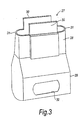
- FIG. 8 of the drawings there is shown a liquid injection system 47 in which an injector 10 is combined with a container 48.
- the container 48 is provided with an inlet tube 49 and the injector 10 is provided with an elongate cowl 50 having a central longitudinal passageway 51 for receiving the inlet tube 49.
- the container 48 is also provided with a laterally extending abutment 53 which may be of a temporary or permanent nature.
- the injector 10 is secured to the container 48 by means of a tape 52 which extends circumferentially around the container 48 and the injector 10 such as to permit movement of the container 11 longitudinally thereof relative to the tape 52 to effect operation of the injector 10, the piston 19 being restrained from such movement by engagement of rim 20 of the piston 19 with the abutment 53 of the container 48.
- the abutment 53 may be temporarily movable to allow the piston 19 to move to pressurise the concentrate and at the same time to move the injector to open the valve to allow concentrate to flow into the container 48. The abutment 53 may then assume its original position. When pressure is released from the injector 10 the valve reseats to close off the flow of concentrate.
- the abutment may be removably by fracture from the container.
- the abutment may be resilient to the extent that passage of the rim 20 may displace it temporarily for the purpose of piston movement and may then resume its original position by virtue of its resilience.
- the tape 52 may be replaced by a collar secured to or integral with the container 48, the injector 10 being insertable therethrough in the manner of a cartridge to register with the inlet tube 49.
- the injector 10 is of generally rectangular cross section and it will be noted that the liner 14 is provided with plunger retainer pins 60 which in the assembled mode register with slots 62 on the side of the piston 19 thereby to define the stroke thereof to ensure that the piston cannot inadvertently be removed from the liner.
- a seal 64 is provided at the relatively upper end of the liner such that when the piston is located therewithin a positive seal is formed to prevent ingress of extraneous matter and the egress of liquid held within the container 11.
- the valve 23 of this embodiment is of slightly different shape than in the first embodiment in terms of the abutment 66 which is adapted for engagement by a nozzle means in the form of an adapter 68.
- a valve sealing surface 70 is formed on the underside of the valve plate 74 supermounting the abutment 66.
- the sealing surface 70 in the closed position of the valve 23 seats on a land (not shown) formed internally and circumferentially of the opening 13 of the container.
- the adapter 68 has a first substantially rectilinear tubular portion 72 leading to a flared skirt portion 73 which is so shaped as to locate over a bottle top, for example a sports cap provided with a conventional pop-up valve arrangement.
- a seal 76 is provided for the portion 72 as shown such that when inserted within the opening 13 sealing is effected to prevent leakage.
- the flared skirt portion 73 has an opening which itself is provided with a seal (not shown) whereby when in position on a bottle cap an effected seal is provided to ensure that during discharge of the concentrate into the bottle substantially no leakage occurs.
- the operation of the second embodiment is identical to that of the first embodiment whereby discharge of the concentrate is effected by a combination of the opening of the valve 23 and the operation of the piston 19.
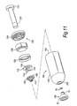
- a third embodiment of liquid injector is provided as shown generally at 100 and has a container 102 of cylindrical form having an outlet 103 for the discharge in use of the contents from the container and an inlet end 104.
- a valve seat 106 is formed circumjacent the outlet 103 and a valve member 108 is adapted for sealing engagement therewith in its closed position (seen in Figure 10).
- the valve member 108 has an apertured head 109 for engagement with the seat 106 and an abutment portion 111 of cruciform shape.
- a land 110 within the container 102 and seated on this land is a perforated disc 112 provided with leaf spring fingers 114 depending therefrom to engage in use the valve member 108.
- the perforations 116 may be so created that the material for the perforations so removed forms the spring fingers 114 as in this embodiment.
- the spring fingers 114 are limited in their movement and at the end of their depression by the valve constitute a stop therefor.
- a plunger 120 comprises a handle 122 with a recessed head 123, the plunger extending through a cap 124 for the top of the container 102 and the cap being suitably held by screw fitment or frictional engagement with said top.
- the handle has fixed on its relatively inner end a plunger head 126 provided with a cupped sealing washer 128 which engages in resilient and sweeping manner the interior of the container as can be seen in Figure 10.
- a nozzle means in the form of an adapter 130 is shown and is of similar form to that (68) of the second embodiment save that the first portion in this embodiment is of tubular cylindrical shape; accordingly the adapter will not be described again but like numerals of reference to those applied in relation to Figure 9 are employed on the Figures 10 and 11.
- the adapter 130 may be accommodated and releasably held within the recessed head 123 of the plunger handle when not in use.
- the container 102 In operation the container 102 is charged with a concentrate in liquid form through the inlet 104 prior to the insertion of the plunger 120, the liquid at that stage being prevented from leaving the container by virtue of the valve 108 being held in a closed position against the seat 106 by the spring fingers 114.
- the concentrate can be introduced through the outlet past the valve 108 once it is lifted off its seat.
- the plunger 120 is then inserted into the container 102 and the cap 124 is closed onto the top of the container as shown in Figure 10. Pressure is applied to the plunger to prime the liquid in the container and the liquid injector is ready for use.
- the adapter 130 is removed from its parked position in the recessed head of the plunger handle and the flared skirt portion 74 of the adapter is fixed over a bottle cap, for example a sports cap (not shown).
- the first portion 72 is then inserted through the outlet 104 and abuts the valve abutment to lift the valve off its seat 106 thereby to allow the discharge of the liquid from the container.
- the liquid effectively flows through the apertured head 109 of the valve into the first portion 72 and the flared portion and thence into the bottle cap and into the bottle.
- the duration of valve lift to effect discharge of the concentrate is determined by the user and thus any volume of liquid can be ejected according to demand, the injector being re-usable in this regard.
- the container is removed from the bottle cap and the spring fingers act to reseat the valve and effect closure of the container thereby preventing egress of its contents.
- the adapter in the form of nozzle means may be permanently disposed in the outlet of the container and thus irremovable therefrom.
- the adapter may during non-use be releasably held in the recessed head of the plunger handle or elsewhere on the container wherever is most convenient.
- the injector may be integral with another container with the valve being actuable by any suitable means externally of the container of the injector; for example a button or lever could extend into the lower part of the injector to contact the valve and be operable to lift it off its seat to allow passage of the concentrate directly into the other container.
- the container may also be used for the discharge of its contents into a receptacle other than a bottle.
- the adapter merely needs to be inserted in the outlet of the container and then pressed to actuate the valve into its open position thus allowing discharge into the receptacle.
- the resilient bias on the valve may be of any convenient form and whilst it has been principally described herein as comprising the leaf spring type, the bias may be constituted by an open coil compression spring or by an elastomeric material or any suitable equivalent thereof.
- the present invention is intended primarily but not solely for use as a cartridge for dispensing a concentrated soft drink for dilution in water or another beverage which could be a soft drink itself or an alcoholic beverage.
Landscapes
- Engineering & Computer Science (AREA)
- Mechanical Engineering (AREA)
- Closures For Containers (AREA)
- Containers And Packaging Bodies Having A Special Means To Remove Contents (AREA)
- Fluid-Driven Valves (AREA)
- Pipeline Systems (AREA)
- Quick-Acting Or Multi-Walled Pipe Joints (AREA)
- Fluid-Pressure Circuits (AREA)
- Electrical Discharge Machining, Electrochemical Machining, And Combined Machining (AREA)
- Nozzles (AREA)
- Liquid Crystal (AREA)
- Reciprocating Pumps (AREA)
- Devices For Dispensing Beverages (AREA)
Applications Claiming Priority (3)
| Application Number | Priority Date | Filing Date | Title |
|---|---|---|---|
| GBGB0109876.3A GB0109876D0 (en) | 2001-04-21 | 2001-04-21 | Liquid injector system |
| GB0109876 | 2001-04-21 | ||
| PCT/GB2002/001825 WO2002085775A1 (en) | 2001-04-21 | 2002-04-19 | Liquid injector system |
Publications (2)
| Publication Number | Publication Date |
|---|---|
| EP1383705A1 EP1383705A1 (en) | 2004-01-28 |
| EP1383705B1 true EP1383705B1 (en) | 2006-02-01 |
Family
ID=9913246
Family Applications (1)
| Application Number | Title | Priority Date | Filing Date |
|---|---|---|---|
| EP02718370A Expired - Lifetime EP1383705B1 (en) | 2001-04-21 | 2002-04-19 | Liquid injector system |
Country Status (12)
| Country | Link |
|---|---|
| US (1) | US7069966B2 (zh) |
| EP (1) | EP1383705B1 (zh) |
| JP (1) | JP2004528241A (zh) |
| AT (1) | ATE316939T1 (zh) |
| CA (1) | CA2482275A1 (zh) |
| DE (1) | DE60209000T2 (zh) |
| DK (1) | DK1383705T3 (zh) |
| ES (1) | ES2260423T3 (zh) |
| GB (1) | GB0109876D0 (zh) |
| HK (1) | HK1064081A1 (zh) |
| PT (1) | PT1383705E (zh) |
| WO (1) | WO2002085775A1 (zh) |
Families Citing this family (4)
| Publication number | Priority date | Publication date | Assignee | Title |
|---|---|---|---|---|
| US6851580B2 (en) | 2003-01-17 | 2005-02-08 | Veltek Associates, Inc. | Mixing and dispensing apparatus |
| US7066354B2 (en) | 2003-01-17 | 2006-06-27 | Stank Robert E | Mixing and dispensing apparatus |
| US10729795B2 (en) | 2004-01-12 | 2020-08-04 | Veltek Associates, Inc. | Method for mixing and dispensing |
| US8523017B2 (en) | 2011-09-22 | 2013-09-03 | Veltek Associates, Inc. | Mixing and dispensing apparatus |
Family Cites Families (4)
| Publication number | Priority date | Publication date | Assignee | Title |
|---|---|---|---|---|
| EP0039245A1 (en) * | 1980-04-30 | 1981-11-04 | Black & Decker | Cartridge assembly |
| GB8903826D0 (en) * | 1989-02-20 | 1989-04-05 | Sandia Investments Sa | Packages for liquids |
| EP0477239B1 (en) * | 1989-06-13 | 1994-08-10 | Sonoco Limited | Connector and disconnectable coupling arrangement for a fluid container |
| US6158628A (en) * | 1999-09-13 | 2000-12-12 | Englram; Paul B. | Viscous fluid delivery system and method and valve therefor |
-
2001
- 2001-04-21 GB GBGB0109876.3A patent/GB0109876D0/en not_active Ceased
-
2002
- 2002-04-19 CA CA002482275A patent/CA2482275A1/en not_active Abandoned
- 2002-04-19 PT PT02718370T patent/PT1383705E/pt unknown
- 2002-04-19 AT AT02718370T patent/ATE316939T1/de not_active IP Right Cessation
- 2002-04-19 WO PCT/GB2002/001825 patent/WO2002085775A1/en active IP Right Grant
- 2002-04-19 DK DK02718370T patent/DK1383705T3/da active
- 2002-04-19 EP EP02718370A patent/EP1383705B1/en not_active Expired - Lifetime
- 2002-04-19 US US10/475,312 patent/US7069966B2/en not_active Expired - Fee Related
- 2002-04-19 DE DE60209000T patent/DE60209000T2/de not_active Expired - Lifetime
- 2002-04-19 ES ES02718370T patent/ES2260423T3/es not_active Expired - Lifetime
- 2002-04-19 JP JP2002583314A patent/JP2004528241A/ja active Pending
-
2004
- 2004-07-27 HK HK04105545A patent/HK1064081A1/xx not_active IP Right Cessation
Also Published As
| Publication number | Publication date |
|---|---|
| DK1383705T3 (da) | 2006-06-12 |
| HK1064081A1 (en) | 2005-01-21 |
| US20040195376A1 (en) | 2004-10-07 |
| JP2004528241A (ja) | 2004-09-16 |
| ES2260423T3 (es) | 2006-11-01 |
| DE60209000D1 (de) | 2006-04-13 |
| DE60209000T2 (de) | 2006-10-05 |
| EP1383705A1 (en) | 2004-01-28 |
| US7069966B2 (en) | 2006-07-04 |
| PT1383705E (pt) | 2006-06-30 |
| WO2002085775A1 (en) | 2002-10-31 |
| GB0109876D0 (en) | 2001-06-13 |
| ATE316939T1 (de) | 2006-02-15 |
| CA2482275A1 (en) | 2002-10-31 |
Similar Documents
| Publication | Publication Date | Title |
|---|---|---|
| EP0254138B1 (en) | Container closure cap with metering appliance | |
| US8047406B2 (en) | Push-botton metered dispenser with feed-containing piston drive mechanism | |
| US5839623A (en) | Reusable pressure spray container | |
| US5842605A (en) | Resuable dispenser for paste, lotion and cream-like materials | |
| EP0380330A1 (en) | Metered dispensing cap for tubes | |
| US20090173752A1 (en) | Dispensing Apparatus | |
| EP1373769B1 (en) | Valve | |
| EP0868392B1 (en) | Liquid container with resealable outlet | |
| US5865350A (en) | Spray bottle with built-in pump | |
| CA2760796A1 (en) | Vented valve assembly | |
| US8499985B2 (en) | Automatic dispensing cap for squeezable bottle | |
| US6779690B2 (en) | Double-acting pump for ejecting a product from a container | |
| US4865230A (en) | Fluid dispenser | |
| US20140151404A1 (en) | Automatic dispensing cap for a squeezeable bottle | |
| US6702160B1 (en) | No spill container | |
| EP1383705B1 (en) | Liquid injector system | |
| US2562317A (en) | Liquid dispenser with a resilient wall pump | |
| US2702957A (en) | Valved closure | |
| US2808966A (en) | Dispensing pump and valve arrangement | |
| US6672485B2 (en) | Metering device for fluid products | |
| GB2086845A (en) | Aerosol Valve | |
| GB2309961A (en) | Liquid dispenser for an inclinable bottle | |
| EP1364719A1 (en) | Dispenser | |
| US20040099696A1 (en) | Method and apparatus for delivering pressurized fluids from storage to a point of use | |
| US10591337B1 (en) | Dispensing cup for aerosol device |
Legal Events
| Date | Code | Title | Description |
|---|---|---|---|
| PUAI | Public reference made under article 153(3) epc to a published international application that has entered the european phase |
Free format text: ORIGINAL CODE: 0009012 |
|
| 17P | Request for examination filed |
Effective date: 20031117 |
|
| AK | Designated contracting states |
Kind code of ref document: A1 Designated state(s): AT BE CH CY DE DK ES FI FR GB GR IE IT LI LU MC NL PT SE TR |
|
| AX | Request for extension of the european patent |
Extension state: AL LT LV MK RO SI |
|
| 17Q | First examination report despatched |
Effective date: 20040226 |
|
| REG | Reference to a national code |
Ref country code: HK Ref legal event code: DE Ref document number: 1064081 Country of ref document: HK |
|
| GRAP | Despatch of communication of intention to grant a patent |
Free format text: ORIGINAL CODE: EPIDOSNIGR1 |
|
| GRAS | Grant fee paid |
Free format text: ORIGINAL CODE: EPIDOSNIGR3 |
|
| GRAA | (expected) grant |
Free format text: ORIGINAL CODE: 0009210 |
|
| AK | Designated contracting states |
Kind code of ref document: B1 Designated state(s): AT BE CH CY DE DK ES FI FR GB GR IE IT LI LU MC NL PT SE TR |
|
| REG | Reference to a national code |
Ref country code: GB Ref legal event code: FG4D |
|
| REG | Reference to a national code |
Ref country code: CH Ref legal event code: EP |
|
| REG | Reference to a national code |
Ref country code: IE Ref legal event code: FG4D |
|
| REF | Corresponds to: |
Ref document number: 60209000 Country of ref document: DE Date of ref document: 20060413 Kind code of ref document: P |
|
| REG | Reference to a national code |
Ref country code: SE Ref legal event code: TRGR |
|
| REG | Reference to a national code |
Ref country code: CH Ref legal event code: NV Representative=s name: NOVAGRAAF INTERNATIONAL SA |
|
| REG | Reference to a national code |
Ref country code: DK Ref legal event code: T3 |
|
| REG | Reference to a national code |
Ref country code: PT Ref legal event code: SC4A Effective date: 20060428 Ref country code: GR Ref legal event code: EP Ref document number: 20060401451 Country of ref document: GR |
|
| ET | Fr: translation filed | ||
| REG | Reference to a national code |
Ref country code: ES Ref legal event code: FG2A Ref document number: 2260423 Country of ref document: ES Kind code of ref document: T3 |
|
| REG | Reference to a national code |
Ref country code: HK Ref legal event code: GR Ref document number: 1064081 Country of ref document: HK |
|
| PLBE | No opposition filed within time limit |
Free format text: ORIGINAL CODE: 0009261 |
|
| STAA | Information on the status of an ep patent application or granted ep patent |
Free format text: STATUS: NO OPPOSITION FILED WITHIN TIME LIMIT |
|
| 26N | No opposition filed |
Effective date: 20061103 |
|
| PGFP | Annual fee paid to national office [announced via postgrant information from national office to epo] |
Ref country code: CH Payment date: 20100317 Year of fee payment: 9 Ref country code: DK Payment date: 20100318 Year of fee payment: 9 Ref country code: IE Payment date: 20100309 Year of fee payment: 9 Ref country code: LU Payment date: 20100331 Year of fee payment: 9 Ref country code: MC Payment date: 20100331 Year of fee payment: 9 Ref country code: PT Payment date: 20100316 Year of fee payment: 9 |
|
| PGFP | Annual fee paid to national office [announced via postgrant information from national office to epo] |
Ref country code: FR Payment date: 20100325 Year of fee payment: 9 Ref country code: IT Payment date: 20100326 Year of fee payment: 9 |
|
| PGFP | Annual fee paid to national office [announced via postgrant information from national office to epo] |
Ref country code: ES Payment date: 20100316 Year of fee payment: 9 |
|
| PGFP | Annual fee paid to national office [announced via postgrant information from national office to epo] |
Ref country code: AT Payment date: 20100317 Year of fee payment: 9 Ref country code: BE Payment date: 20100322 Year of fee payment: 9 Ref country code: DE Payment date: 20100419 Year of fee payment: 9 Ref country code: NL Payment date: 20100402 Year of fee payment: 9 |
|
| PGFP | Annual fee paid to national office [announced via postgrant information from national office to epo] |
Ref country code: CY Payment date: 20100419 Year of fee payment: 9 Ref country code: SE Payment date: 20100324 Year of fee payment: 9 Ref country code: TR Payment date: 20100405 Year of fee payment: 9 |
|
| PGFP | Annual fee paid to national office [announced via postgrant information from national office to epo] |
Ref country code: GR Payment date: 20100329 Year of fee payment: 9 |
|
| REG | Reference to a national code |
Ref country code: CH Ref legal event code: PFA Owner name: KUMAR, NEILAN KRISHNA Free format text: KUMAR, NEILAN KRISHNA#28 HILLCROSS AVENUE, MORDEN#LONDON SM4 4EA (GB) -TRANSFER TO- KUMAR, NEILAN KRISHNA#28 HILLCROSS AVENUE, MORDEN#LONDON SM4 4EA (GB) |
|
| REG | Reference to a national code |
Ref country code: PT Ref legal event code: MM4A Free format text: LAPSE DUE TO NON-PAYMENT OF FEES Effective date: 20111019 |
|
| BERE | Be: lapsed |
Owner name: *KUMAR NEILAN KRISHNA Effective date: 20110430 |
|
| REG | Reference to a national code |
Ref country code: NL Ref legal event code: V1 Effective date: 20111101 |
|
| REG | Reference to a national code |
Ref country code: SE Ref legal event code: EUG |
|
| PG25 | Lapsed in a contracting state [announced via postgrant information from national office to epo] |
Ref country code: MC Free format text: LAPSE BECAUSE OF NON-PAYMENT OF DUE FEES Effective date: 20110430 |
|
| REG | Reference to a national code |
Ref country code: CH Ref legal event code: PL |
|
| REG | Reference to a national code |
Ref country code: AT Ref legal event code: MM01 Ref document number: 316939 Country of ref document: AT Kind code of ref document: T Effective date: 20110419 |
|
| REG | Reference to a national code |
Ref country code: GR Ref legal event code: ML Ref document number: 20060401451 Country of ref document: GR Effective date: 20111102 |
|
| REG | Reference to a national code |
Ref country code: FR Ref legal event code: ST Effective date: 20111230 |
|
| PG25 | Lapsed in a contracting state [announced via postgrant information from national office to epo] |
Ref country code: FR Free format text: LAPSE BECAUSE OF NON-PAYMENT OF DUE FEES Effective date: 20110502 Ref country code: FI Free format text: LAPSE BECAUSE OF NON-PAYMENT OF DUE FEES Effective date: 20110419 Ref country code: NL Free format text: LAPSE BECAUSE OF NON-PAYMENT OF DUE FEES Effective date: 20111101 Ref country code: PT Free format text: LAPSE BECAUSE OF NON-PAYMENT OF DUE FEES Effective date: 20111019 Ref country code: CH Free format text: LAPSE BECAUSE OF NON-PAYMENT OF DUE FEES Effective date: 20110430 Ref country code: LI Free format text: LAPSE BECAUSE OF NON-PAYMENT OF DUE FEES Effective date: 20110430 Ref country code: DE Free format text: LAPSE BECAUSE OF NON-PAYMENT OF DUE FEES Effective date: 20111101 Ref country code: BE Free format text: LAPSE BECAUSE OF NON-PAYMENT OF DUE FEES Effective date: 20110430 |
|
| REG | Reference to a national code |
Ref country code: IE Ref legal event code: MM4A |
|
| REG | Reference to a national code |
Ref country code: DK Ref legal event code: EBP |
|
| PG25 | Lapsed in a contracting state [announced via postgrant information from national office to epo] |
Ref country code: GR Free format text: LAPSE BECAUSE OF NON-PAYMENT OF DUE FEES Effective date: 20111102 Ref country code: CY Free format text: LAPSE BECAUSE OF NON-PAYMENT OF DUE FEES Effective date: 20110419 Ref country code: AT Free format text: LAPSE BECAUSE OF NON-PAYMENT OF DUE FEES Effective date: 20110419 Ref country code: IT Free format text: LAPSE BECAUSE OF NON-PAYMENT OF DUE FEES Effective date: 20110419 |
|
| REG | Reference to a national code |
Ref country code: DE Ref legal event code: R119 Ref document number: 60209000 Country of ref document: DE Effective date: 20111101 |
|
| PG25 | Lapsed in a contracting state [announced via postgrant information from national office to epo] |
Ref country code: IE Free format text: LAPSE BECAUSE OF NON-PAYMENT OF DUE FEES Effective date: 20110419 |
|
| REG | Reference to a national code |
Ref country code: ES Ref legal event code: FD2A Effective date: 20120604 |
|
| PG25 | Lapsed in a contracting state [announced via postgrant information from national office to epo] |
Ref country code: DK Free format text: LAPSE BECAUSE OF NON-PAYMENT OF DUE FEES Effective date: 20110430 |
|
| PG25 | Lapsed in a contracting state [announced via postgrant information from national office to epo] |
Ref country code: ES Free format text: LAPSE BECAUSE OF NON-PAYMENT OF DUE FEES Effective date: 20110420 |
|
| PGFP | Annual fee paid to national office [announced via postgrant information from national office to epo] |
Ref country code: FI Payment date: 20100322 Year of fee payment: 9 |
|
| PG25 | Lapsed in a contracting state [announced via postgrant information from national office to epo] |
Ref country code: SE Free format text: LAPSE BECAUSE OF NON-PAYMENT OF DUE FEES Effective date: 20110420 |
|
| PG25 | Lapsed in a contracting state [announced via postgrant information from national office to epo] |
Ref country code: LU Free format text: LAPSE BECAUSE OF NON-PAYMENT OF DUE FEES Effective date: 20110419 |
|
| PG25 | Lapsed in a contracting state [announced via postgrant information from national office to epo] |
Ref country code: TR Free format text: LAPSE BECAUSE OF NON-PAYMENT OF DUE FEES Effective date: 20110419 |
|
| PGFP | Annual fee paid to national office [announced via postgrant information from national office to epo] |
Ref country code: GB Payment date: 20150601 Year of fee payment: 14 |
|
| GBPC | Gb: european patent ceased through non-payment of renewal fee |
Effective date: 20160419 |
|
| PG25 | Lapsed in a contracting state [announced via postgrant information from national office to epo] |
Ref country code: GB Free format text: LAPSE BECAUSE OF NON-PAYMENT OF DUE FEES Effective date: 20160419 |